 gabriel stacey-chartrand
gabriel stacey-chartrand
gabriel stacey-chartrand
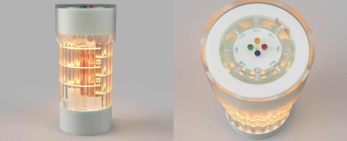
 intermission object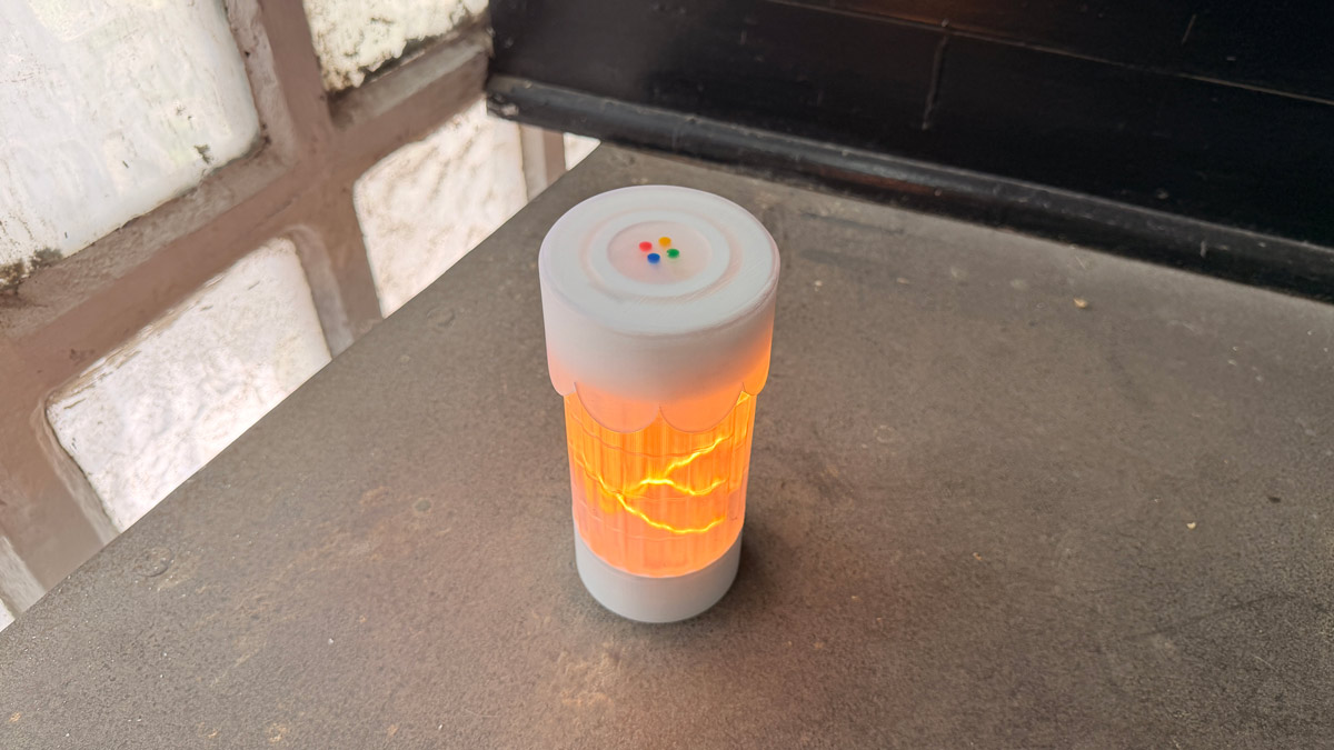
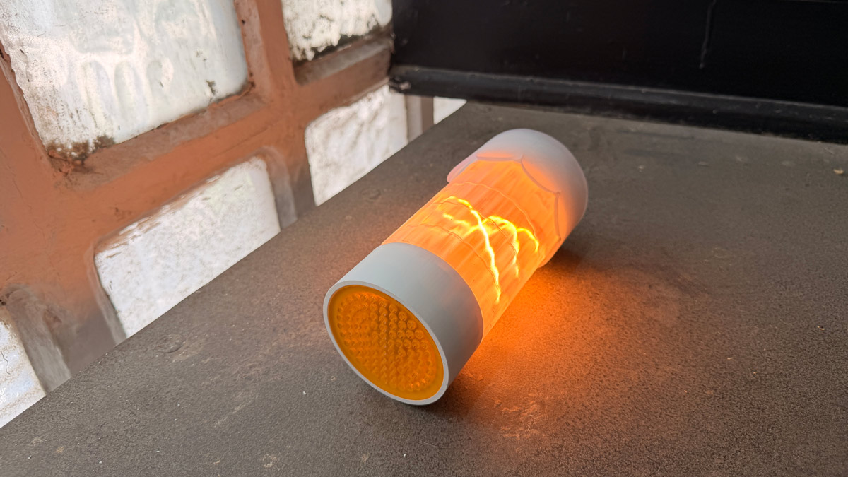
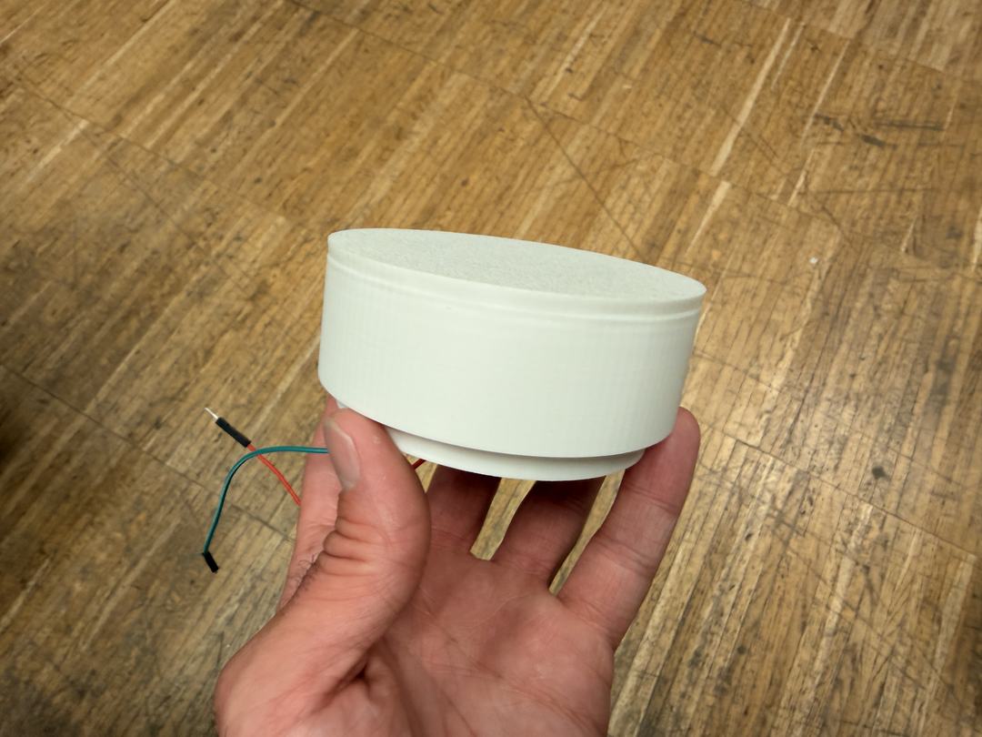
Intermission Object is a handheld ritual device for finite, screenless breaks.
The project explores how a physical object can make taking a break feel intentional and complete without using screens, numbers, or cigarettes.
Instead of watching time count down, the user feels time passing through the object.
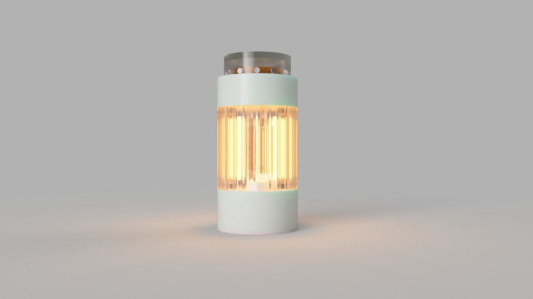
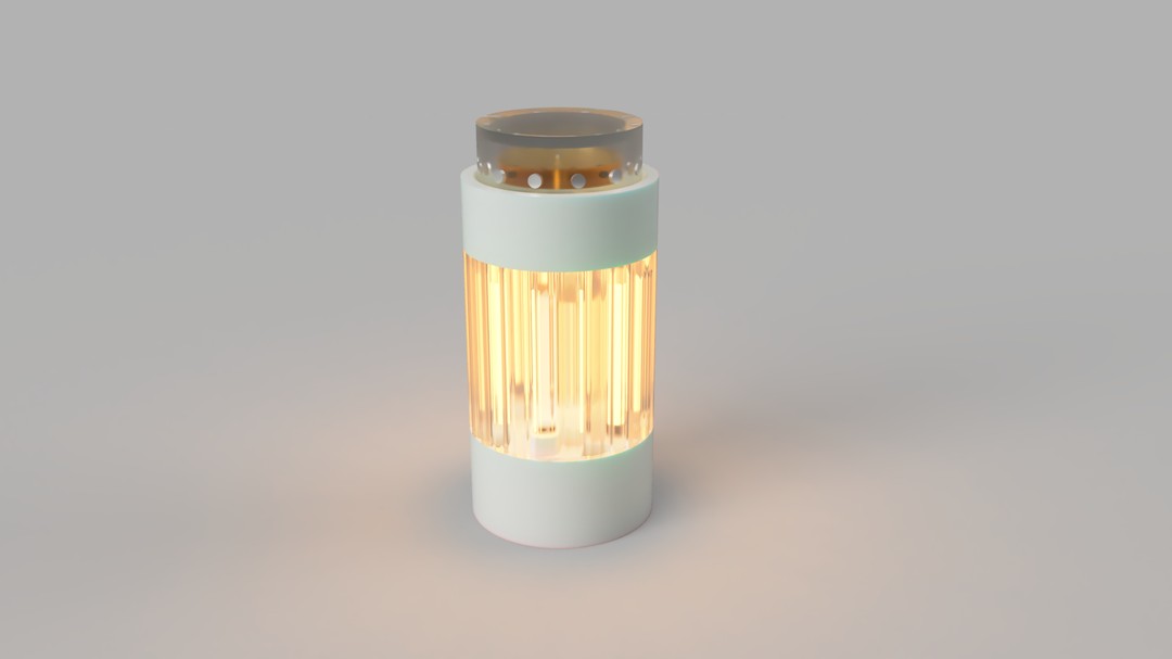
The object is held in one hand and interacted with through a rotating dial. Warm light, gentle haptics, subtle sound, and tactile motion create a break experience that can be influenced, but not fully controlled.
The device is designed to be engaging enough to replace the urge to check a phone, but finite enough that it does not become another endless distraction.
The user does not need to stare at it the whole time. The object is tactile and responsive without demanding visual attention the way a phone does.
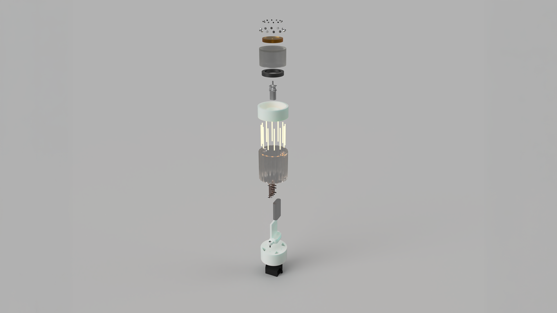
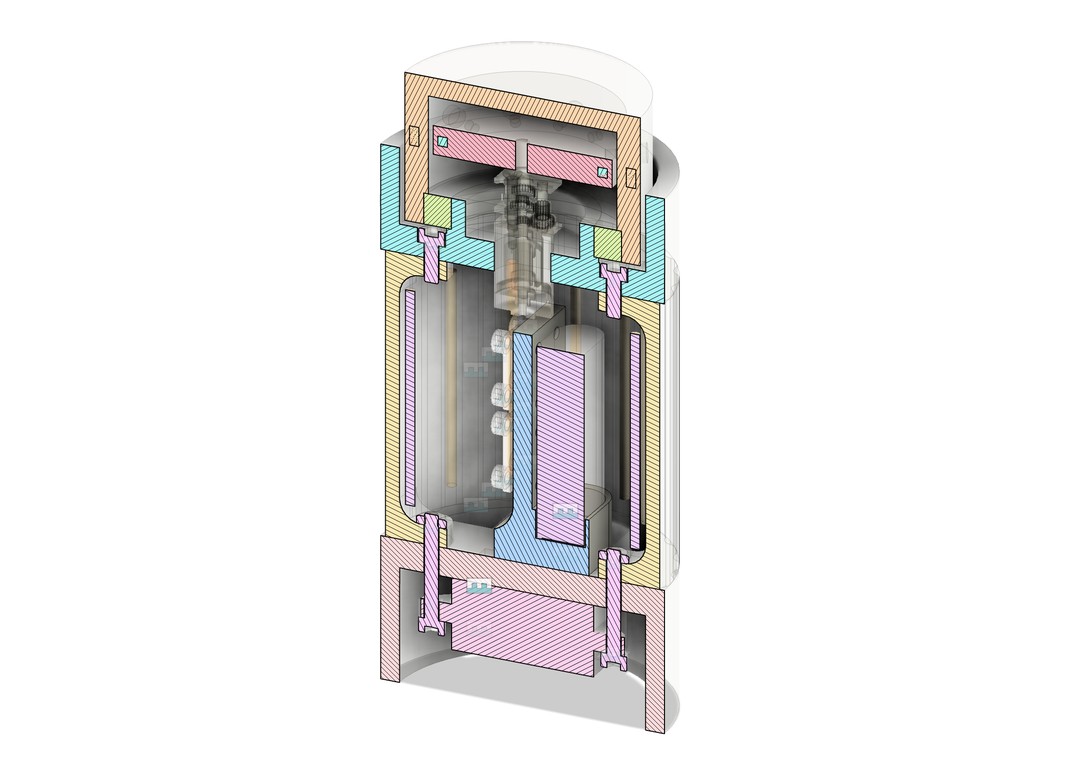
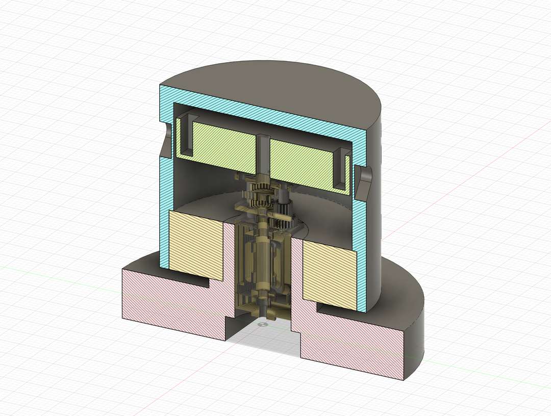
The device uses a magnetically coupled dial mechanism. A motor slowly drives an internal ring with steel pins, which is coupled to an outer dial with embedded magnets.
When the user lets go, the outer dial rotates with the internal mechanism. When they hold the dial still, the magnetic coupling slips. This allows the user to feel soft magnetic pulses passing underneath their fingers as the internal ring continues to move.
This creates a tactile sense of time passing. The user can interact with the object and influence the character of the experience, but they cannot simply skip to the end.
The user begins by picking up the object and deliberately interacting with the dial. This starts the intermission.
As the experience begins, the object emits a warm glow and gives a subtle haptic confirmation. The internal mechanism starts moving slowly, creating tactile motion through the outer dial.
During the break, the user can hold the dial, let it move, or occasionally resist it. When they hold it still, the internal magnetic ring slips underneath, creating soft pulses that can be felt through the fingers.
Light, haptics, and sound respond to the state of the interaction.
The duration of the intermission is not fully controlled by the user. Their interaction influences the pace and feeling of the experience, while the device maintains its own internal rhythm.
At the end of the intermission, the object settles. The motion stops, the light changes or fades, and a gentle haptic or sound cue signals closure.
For me, good design sits between aesthetics, usability, and inclusivity.
Aesthetic quality matters. Beautiful objects can improve everyday wellbeing and quality of life.
User experience is equally important. An object should be intuitive and enjoyable to use (low cognitive load).
Accessibility is essential. The experience should be just as meaningful for someone with visual impairments as it is for a sighted user. This could mean using touch, sound, and physical feedback.
I want this project to be:
Much of this project is informed by my experience with ADHD. Firstly, relating to time blindness and difficulty sensing the passage of time. Secondly, the difficulty of staying focused, moving between tasks, and not being sucked in by distractions (a phone, for example).
Smoking is a useful reference here, not for the act itself, but for the ritual it creates. A cigarette segments time. It has a clear start, duration, and end. I often found my best creative ideas during smoke breaks. It allows you to take a break, forces a change of scenery, and gives you one specific thing to focus on. There's also a ritualistic element in the tactile aspects of smoking a cigarette.
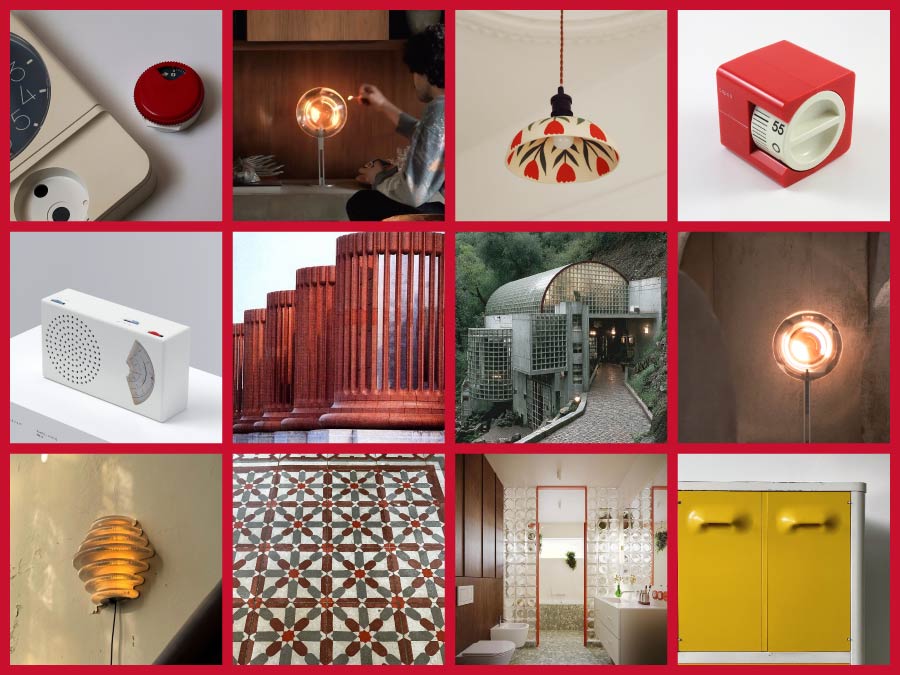
I started questioning traditional clocks and alarm clocks. They are precise, but often stressful. I'm interested in a relative-time object that communicates a finite experience without numbers. The kitchen timer is a source of inspiration for the mechanism and form of the object, but the goal would be more to emulate the ritualistic experience of having a cigarette.
Tech as ritual: "the goal would be more to emulate the ritualistic experience of having a cigarette"
Time could be communicated physically, through the position of a dial or mechanism. Sound and haptics could accompany this, making the experience accessible to blind or visually impaired users.
A proximity sensor could detect someone approaching and draw attention to itself, encouraging interaction. I'd like to explore using PIR or mmWave.
The ritual should be finite. There is no snooze. Once it ends, you move on. Closure is part of the design.
The experience could also be analogous to striking a match.
I'm interested in a final, satisfying settling moment that combines movement, sound, haptic feedback, and light.
A stepper motor could be used for the rotation and mechanical functioning of the dial during the experience.
Ideally, the ritual begins automatically as you approach or touch the object.
Think:
"I step away from my desk and go to the object."
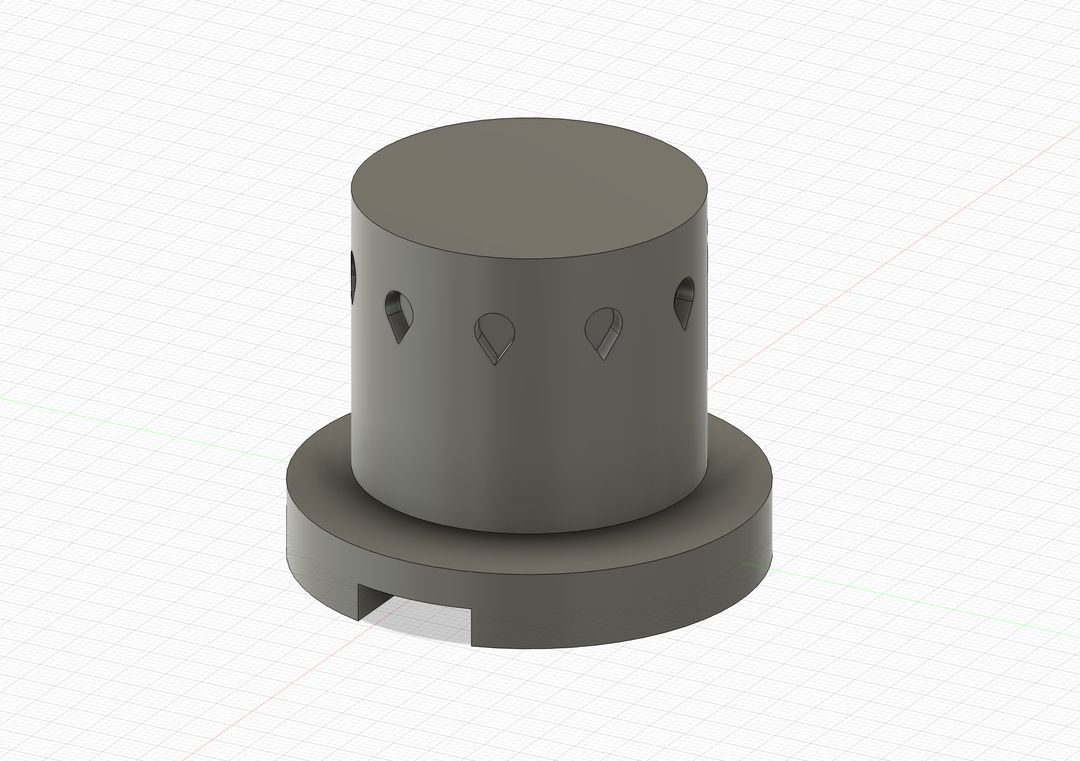
I quickly created a draft model of my object in Fusion in order to get an idea of the shape, form, and dimensions of my object. This allowed me to start to figure out how all the components might fit together and how that might change the overall form of the object.
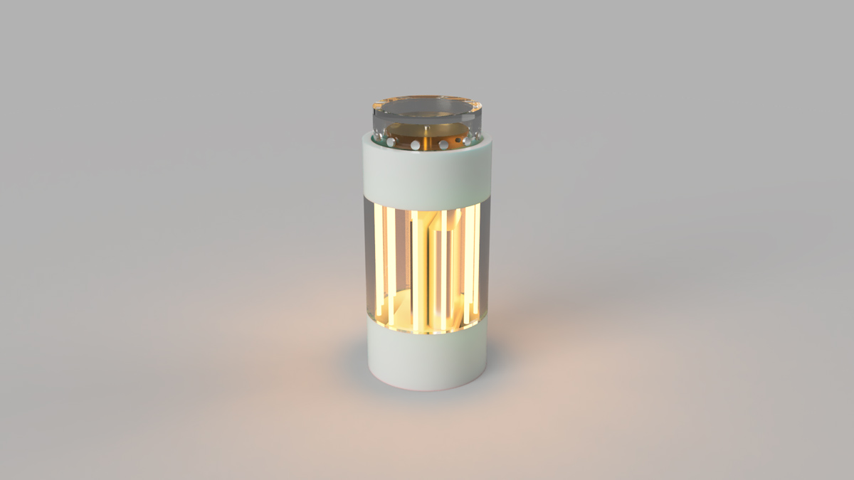
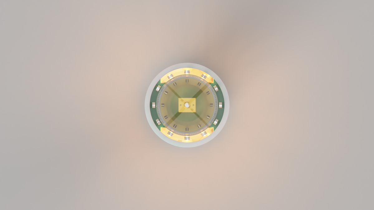
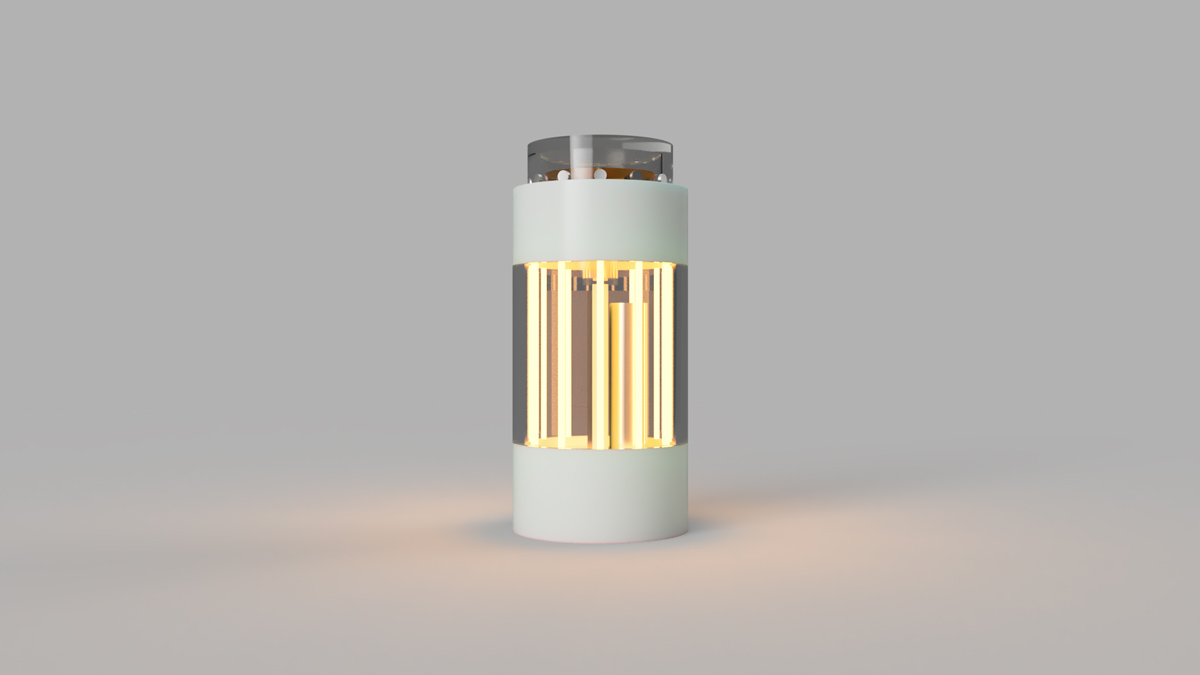
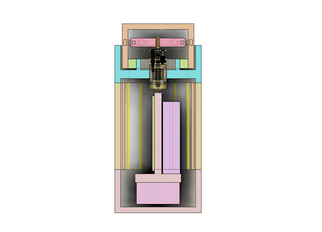
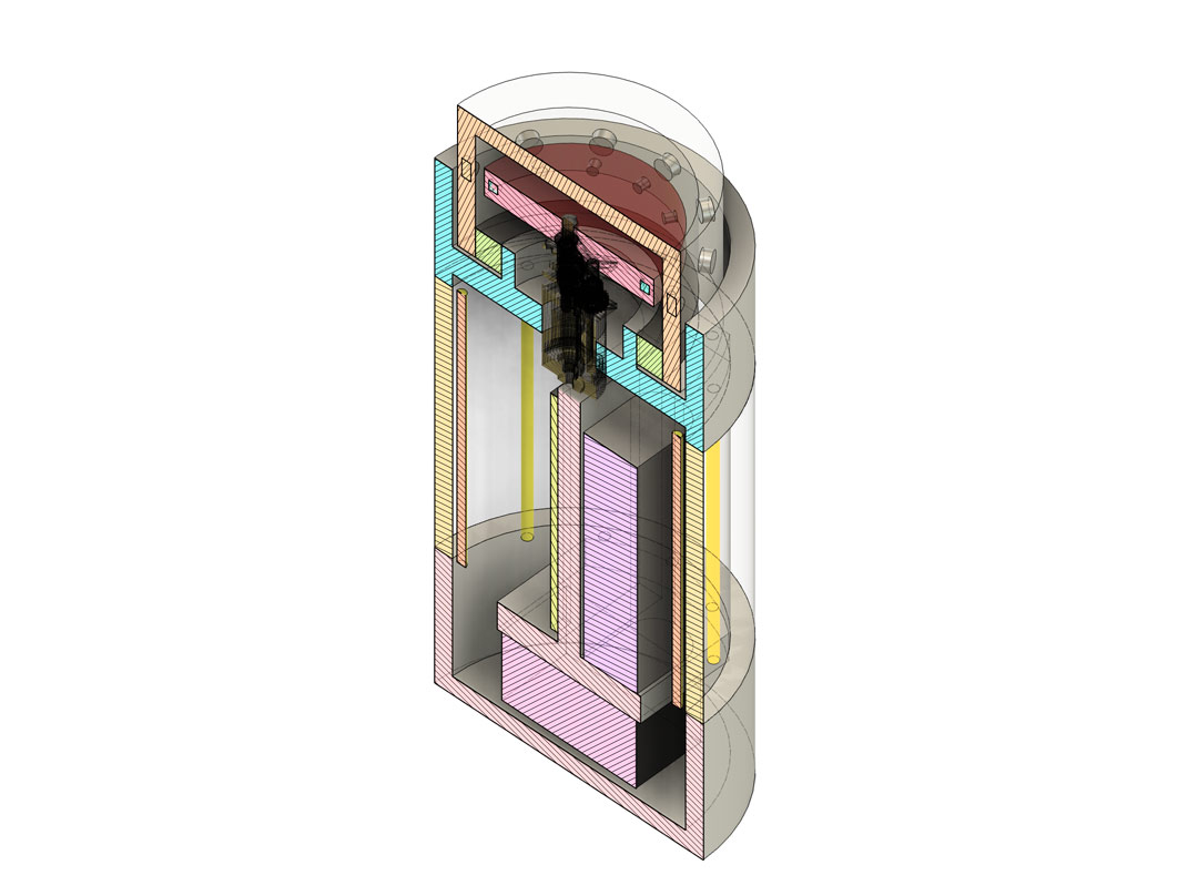
After the first draft, I redesigned to start mounting components in a logical way — adding mounting tabs, holes, and fasteners.
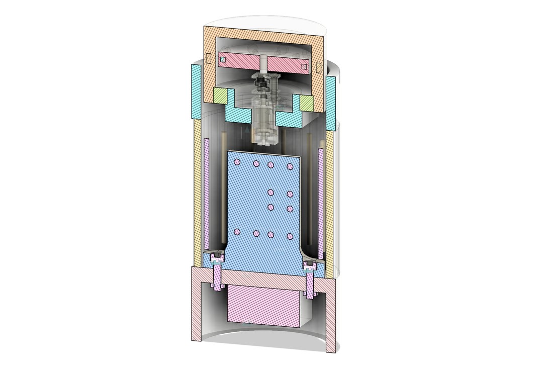
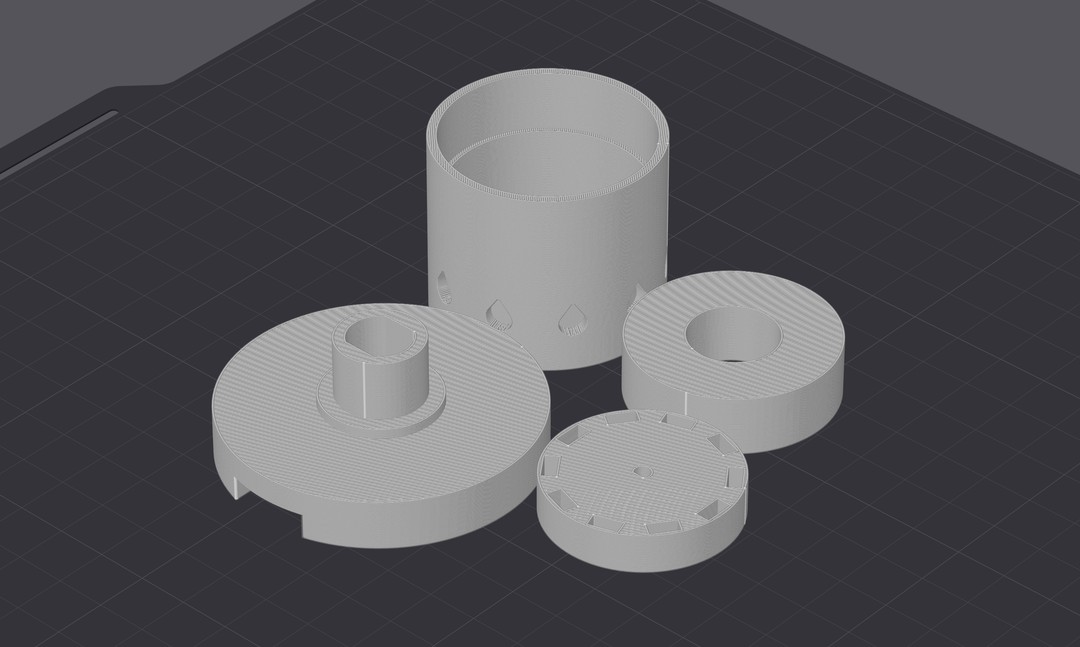
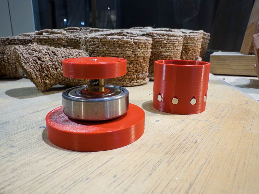
I quickly redesigned the magnetic differential to be able to print and test the effect. I used magnets on the outer dial and steel nuts on the driven inner rotor.
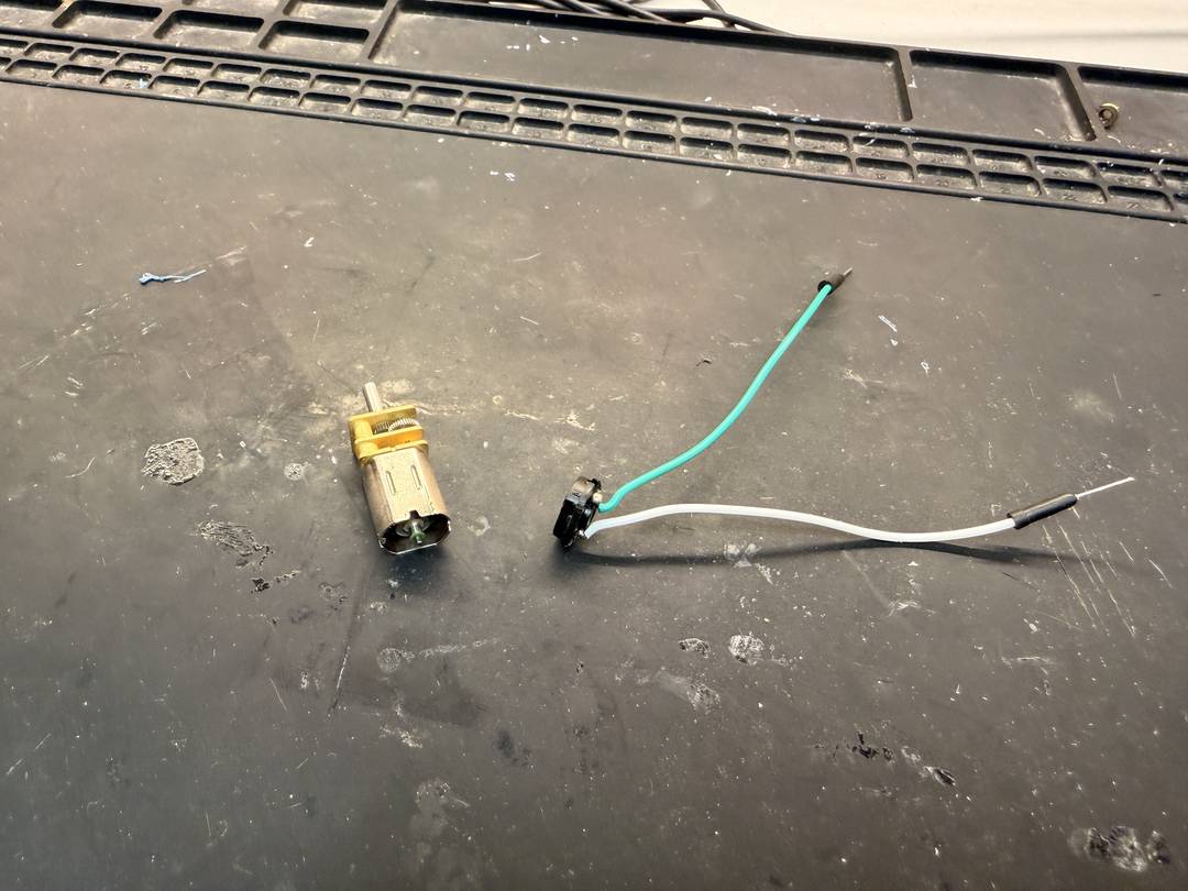
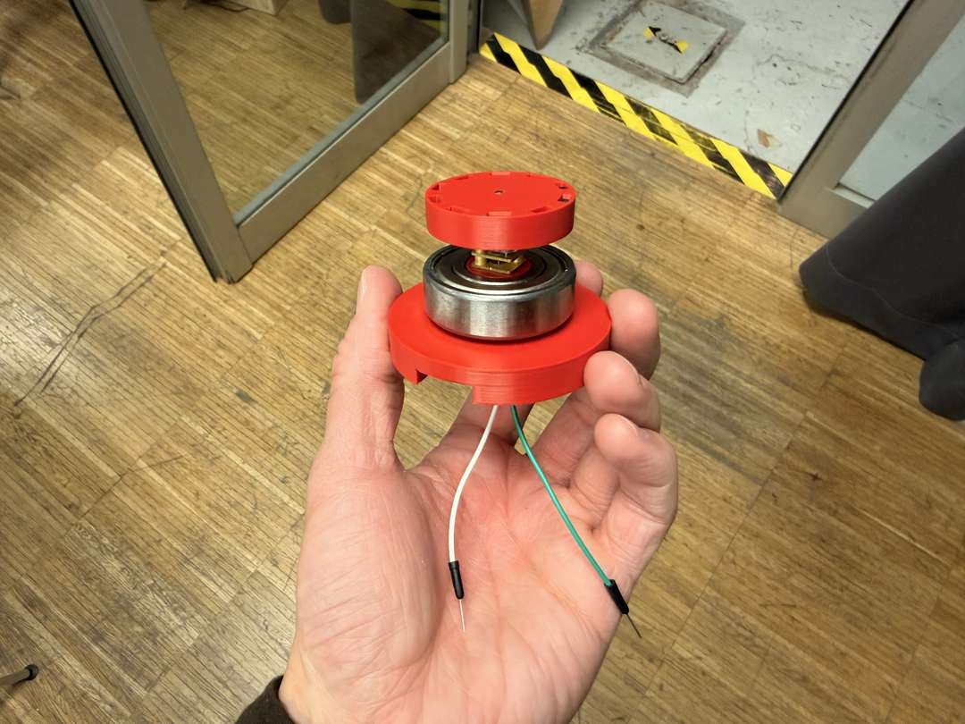
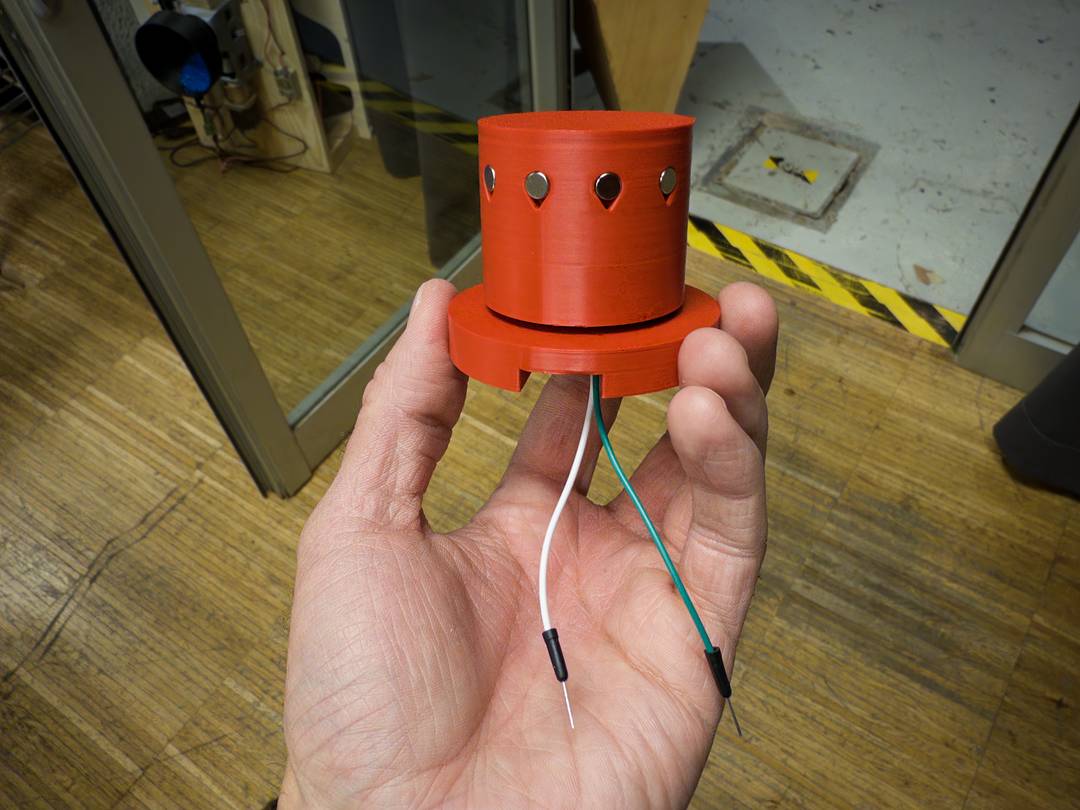
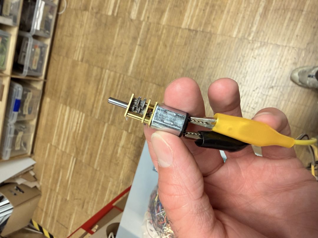
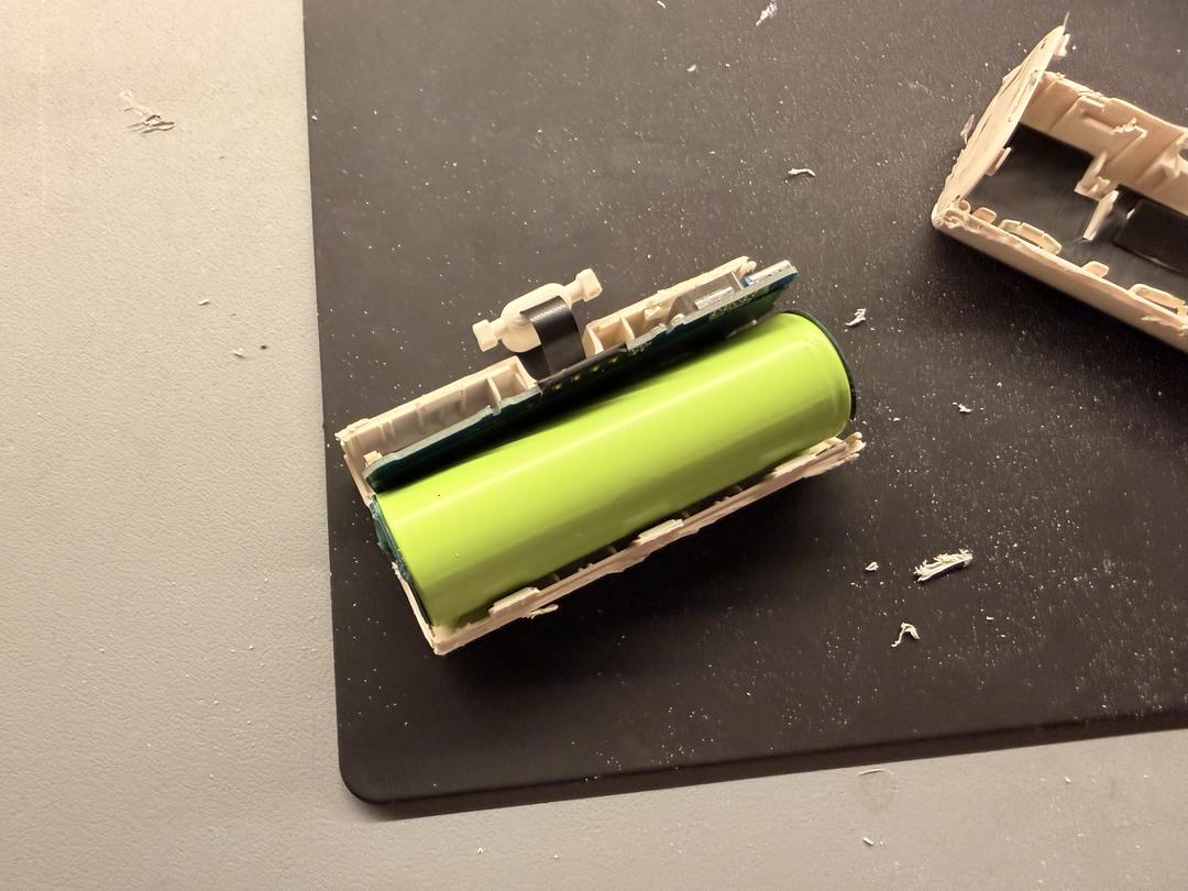
I took a 5000 mAh Anker battery bank apart to keep just the cell and its board: the charging circuitry and two USB-C ports.
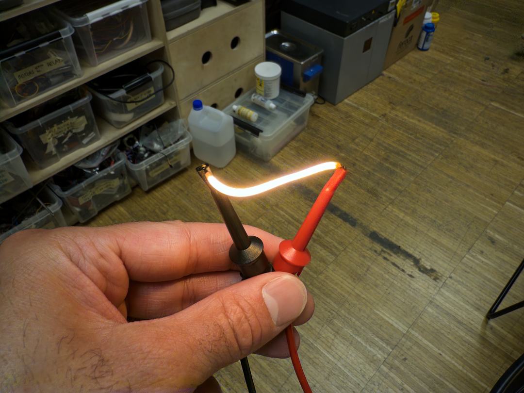
I tested an LED filament directly with a power supply just to confirm it worked.
Then I tested multiple filaments in parallel with a MOSFET and LDO, doing PWM dimming on a breadboard.
I tested the hall effect sensor by hand by holding it next to the magnetic dial and connected it with wires to my breadboard.
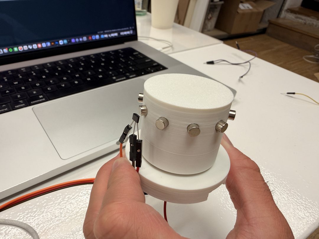
I tested the LRA haptic actuator using the DFRobot TM6605 library.
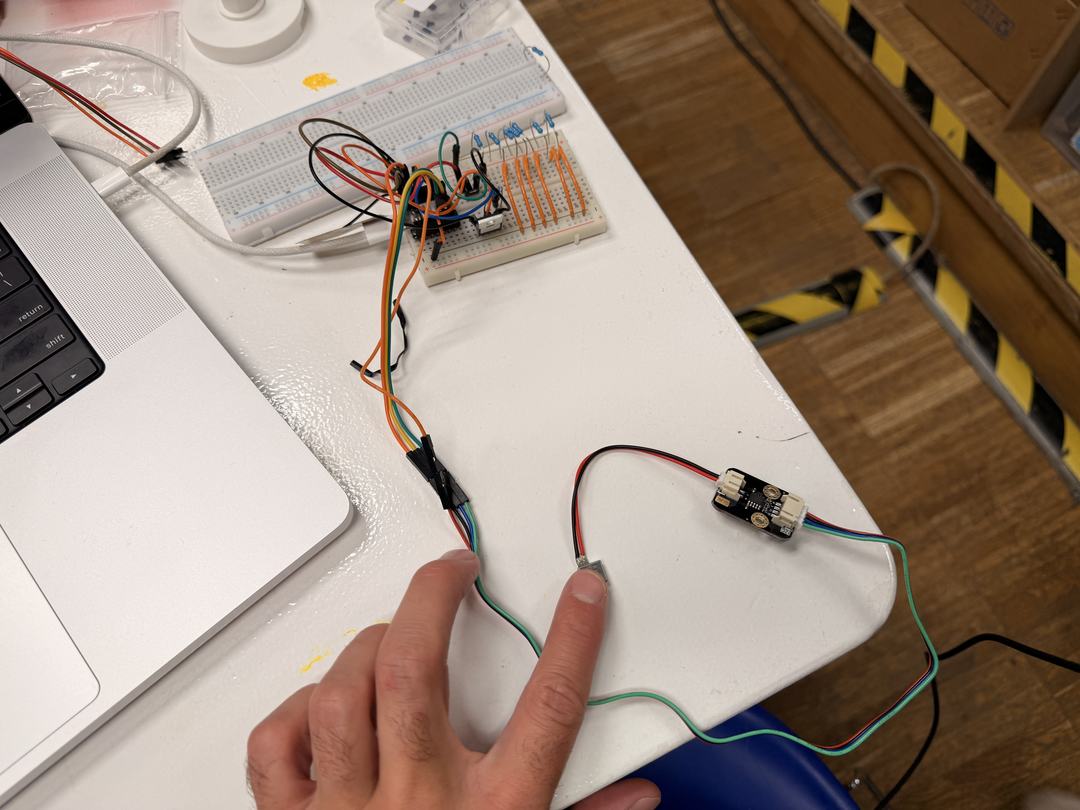
Before designing the mount, I checked how the battery bank and LRA driver could sit together inside the enclosure.
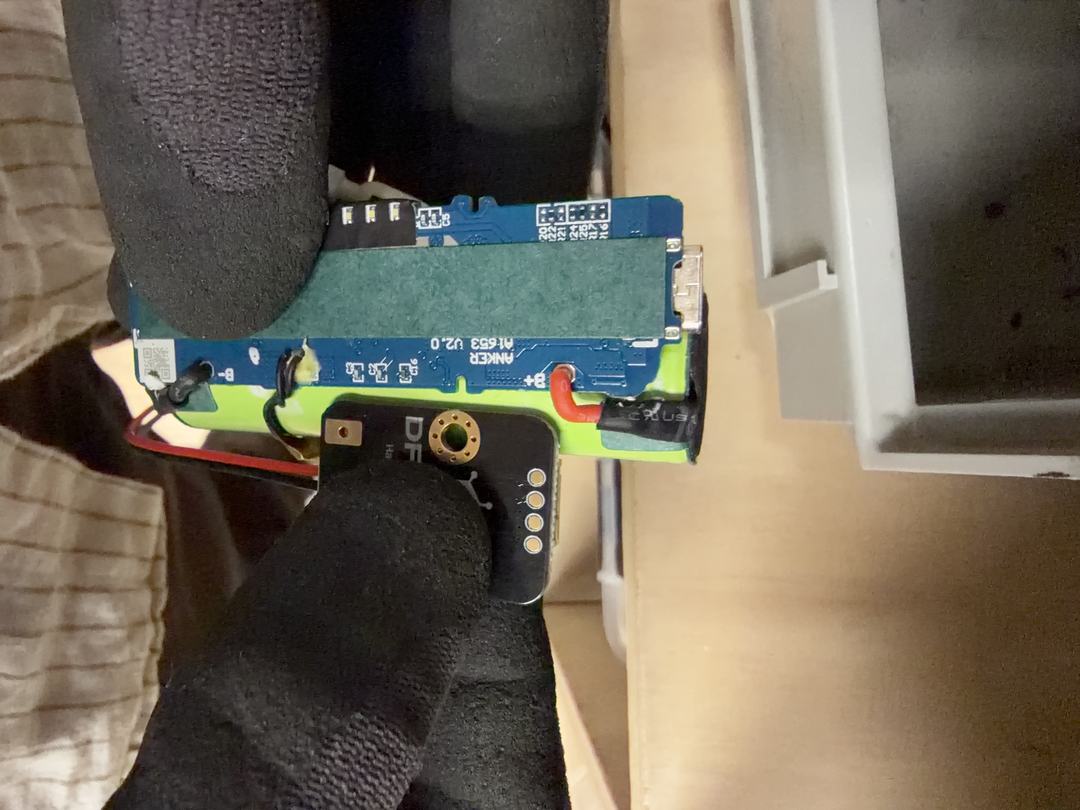
With all the components working individually, I tested them all together on a breadboard.
Before writing the main firmware, I tested each component individually and then progressively combined them. The sketches below are the actual test files from that process, in roughly the order I wrote them. They became the building blocks for the final firmware: the Hall sensor ISR, the TM6605 initialisation pattern, the LED PWM frequency and breath envelope, and the I2S audio setup all came directly from confirmed-working test code.
| Reference | Component | Value / part number | Qty |
|---|---|---|---|
| M1 | Microcontroller | Seeed XIAO ESP32-S3 | 1 |
| U1 | LDO voltage regulator | ZLD01117QG33TADIC — 3.3V / 1A, SOT-223 | 1 |
| Q1, Q2 | N-channel MOSFET | SSM3K333R — Toshiba, SOT-23F | 2 |
| D1 | Schottky diode | SSC54-E3/57T — 40V / 5A, SMC | 1 |
| C1, C2 | Electrolytic capacitor | 100µF / 10V — Panasonic EEE-FN1E101UL | 2 |
| C3 | Ceramic capacitor | 100nF, 1206 | 1 |
| C4, C5 | Ceramic capacitor | 10µF X7R, 1206 | 2 |
| R2, R3 | Resistor | 100Ω, 1206 | 2 |
| R1, R4, R5 | Resistor | 10kΩ, 1206 | 3 |
| R_LED1–6 | Resistor | 10Ω, 1206 | 6 |
| J1 | Terminal block 2-pin | OnShore ED555 — 3.50mm pitch | 1 |
| J2 | Terminal block 2-pin | OnShore ED555 — 3.50mm pitch | 1 |
| J3 | Pin header 7-pin | 2.54mm vertical THT | 1 |
| J4 | Terminal block 2-pin | OnShore ED555 — 3.50mm pitch | 1 |
| J5 | Terminal block 3-pin | 2.54mm pitch | 1 |
| J6 | Terminal block 2-pin | OnShore ED555 — 3.50mm pitch | 1 |
| Component | Part | Connects via | Qty |
|---|---|---|---|
| I2S amplifier | MAX98357A — Adafruit breakout | J3 | 1 |
| Haptic driver | DFRobot Gravity TM6605 (DRI0056) | J4, J6 | 1 |
| Hall effect sensor | A3144 digital switch | J5 | 1 |
| DC geared motor | N20 15RPM | J2 | 1 |
| Speaker | 3W / 8Ω | J3 | 1 |
| COB LED filament | 140mm / 3V / 100mA | J1 | 6 |
| LRA haptic actuator | LRA motor | J4 | 1 |
| Battery bank | 5V USB-C, 5000mAh | XIAO USB-C | 1 |
| Component | Material / process | Notes | Qty |
|---|---|---|---|
| Base | PLA — FFF printed | Houses speaker chamber and electronics mount | 1 |
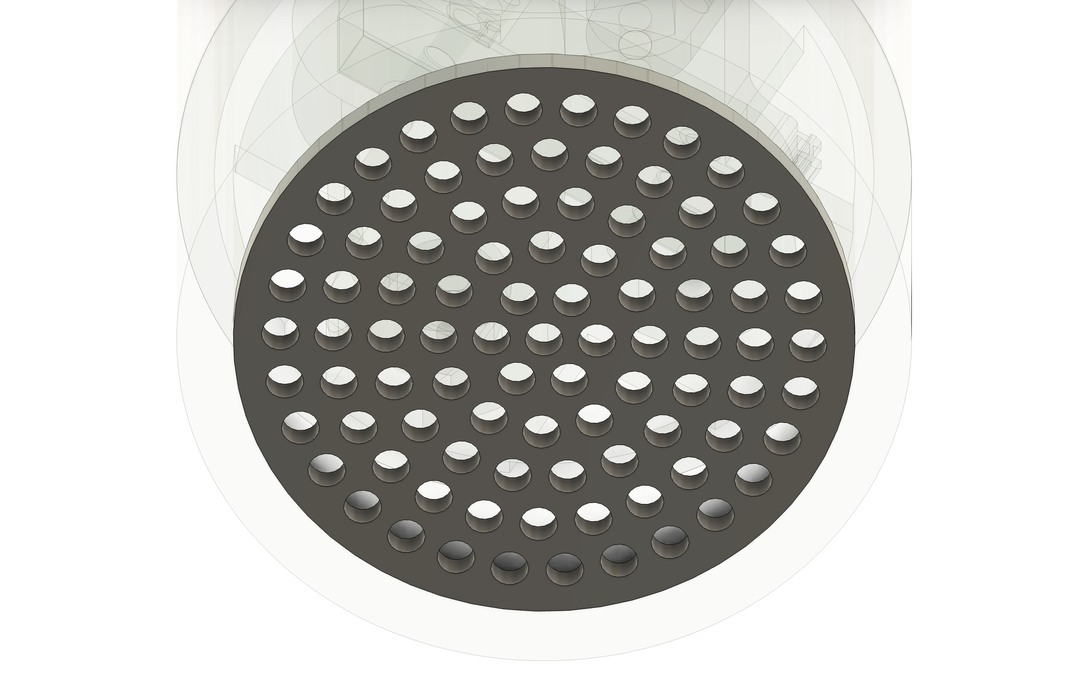
| Speaker grille | Laser cut | Screws onto base | 1 |
| Middle section | Clear resin — SLA printed | Ribbed for light diffusion | 1 |
| Top dial | Clear resin — SLA printed | Logo cavity filled with coloured epoxy resin | 1 |
| Top enclosure | PLA — FFF printed | Houses motor, bearing, and hall effect sensor board | 1 |
| Inner rotor | PLA — FFF printed | Fitted with steel nuts for magnetic coupling | 1 |
| Bearing | 40×17×12mm | Seated in top enclosure to support dial rotation | 1 |
| Neodymium magnets | 5×5mm cylindrical | Embedded in outer dial for magnetic coupling | 8 |
| Hex nut — carbon steel | M3 | Pressed into inner rotor for magnetic differential | 8 |
| Component | Specification | Qty | |
|---|---|---|---|
| Machine screw | M2.5 | 10 | |
| Machine screw | M3 | 8 | |
| Heat set insert | M3 | 6 | |
| Heat set insert | M2.5 | 4 | |
| Hex nut | M2.5 | 6 |
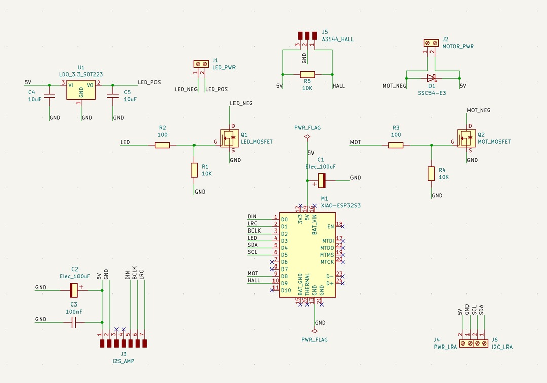
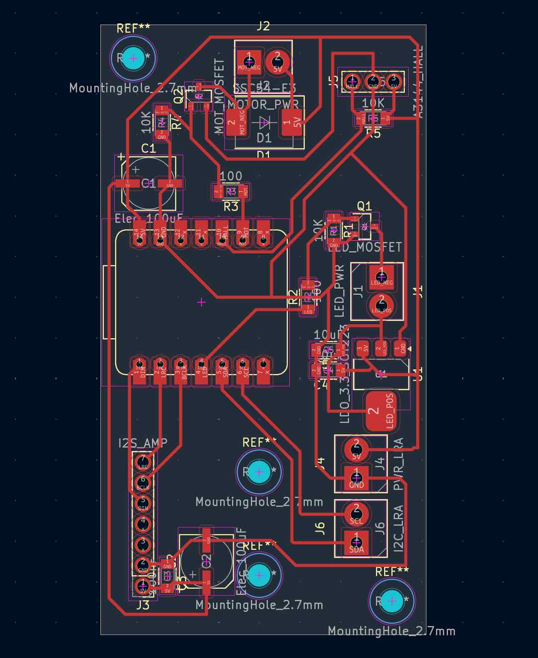
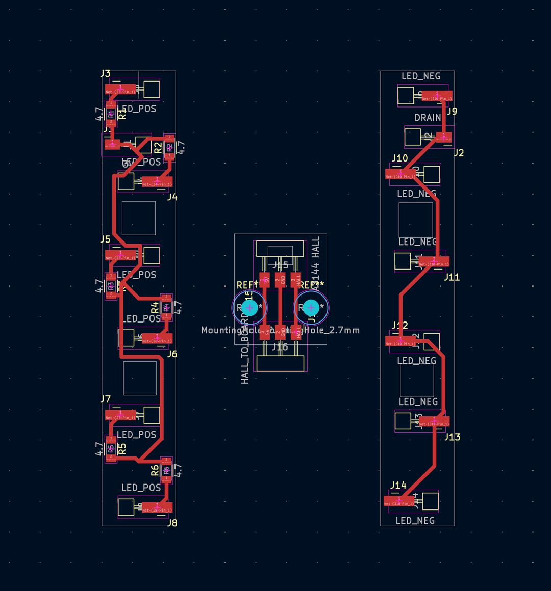
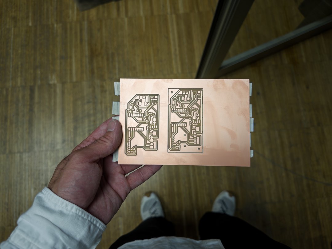
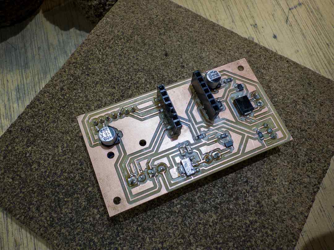
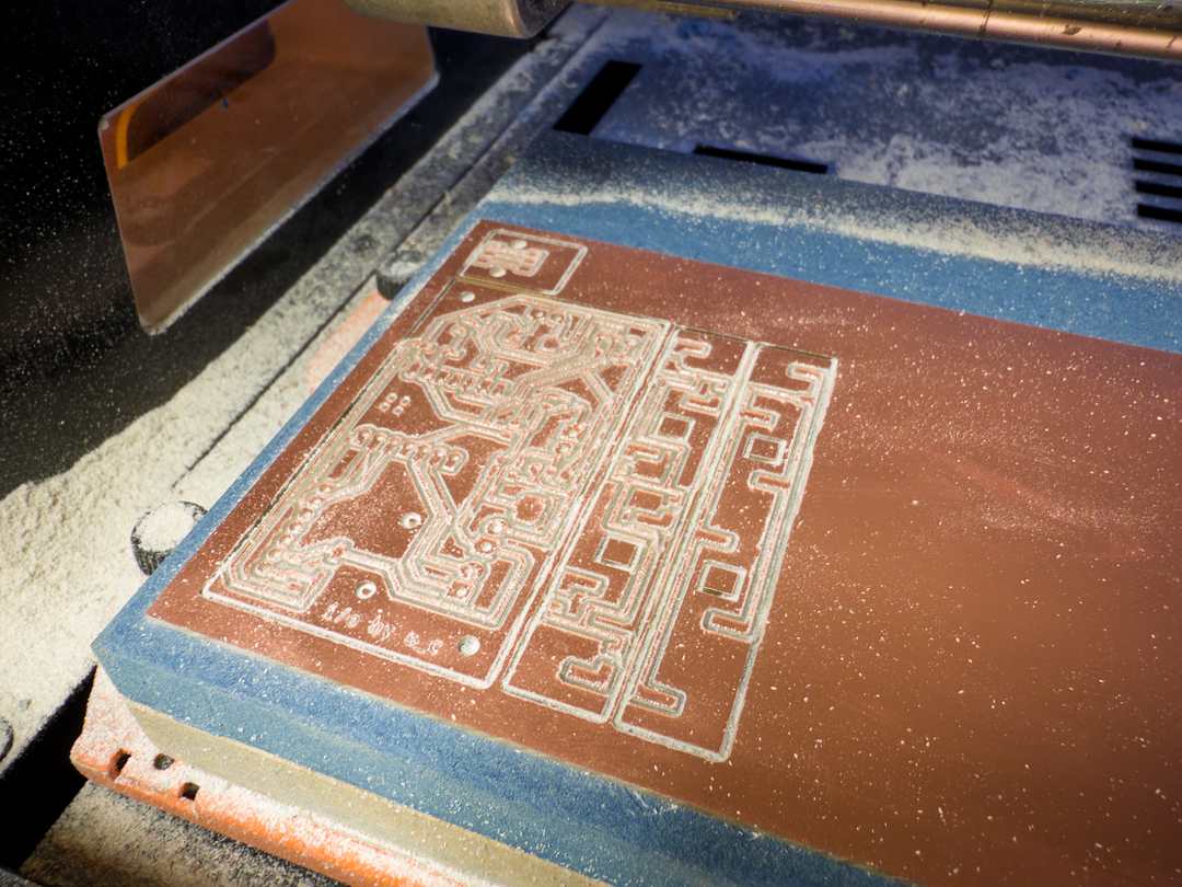
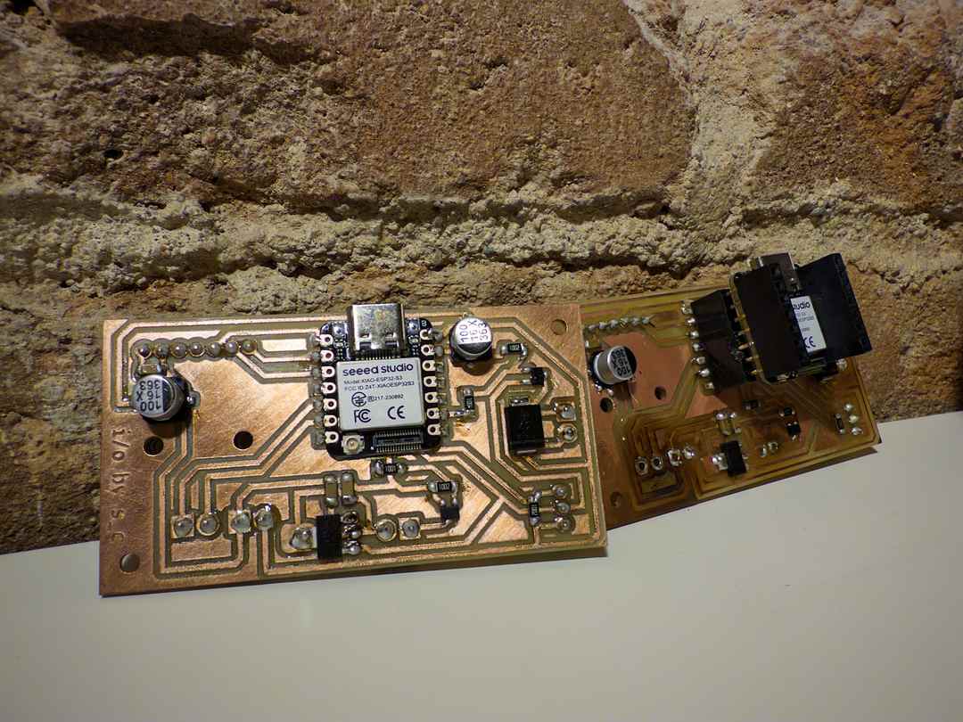
My first milling attempt had two traces too close together. The second came out clean.
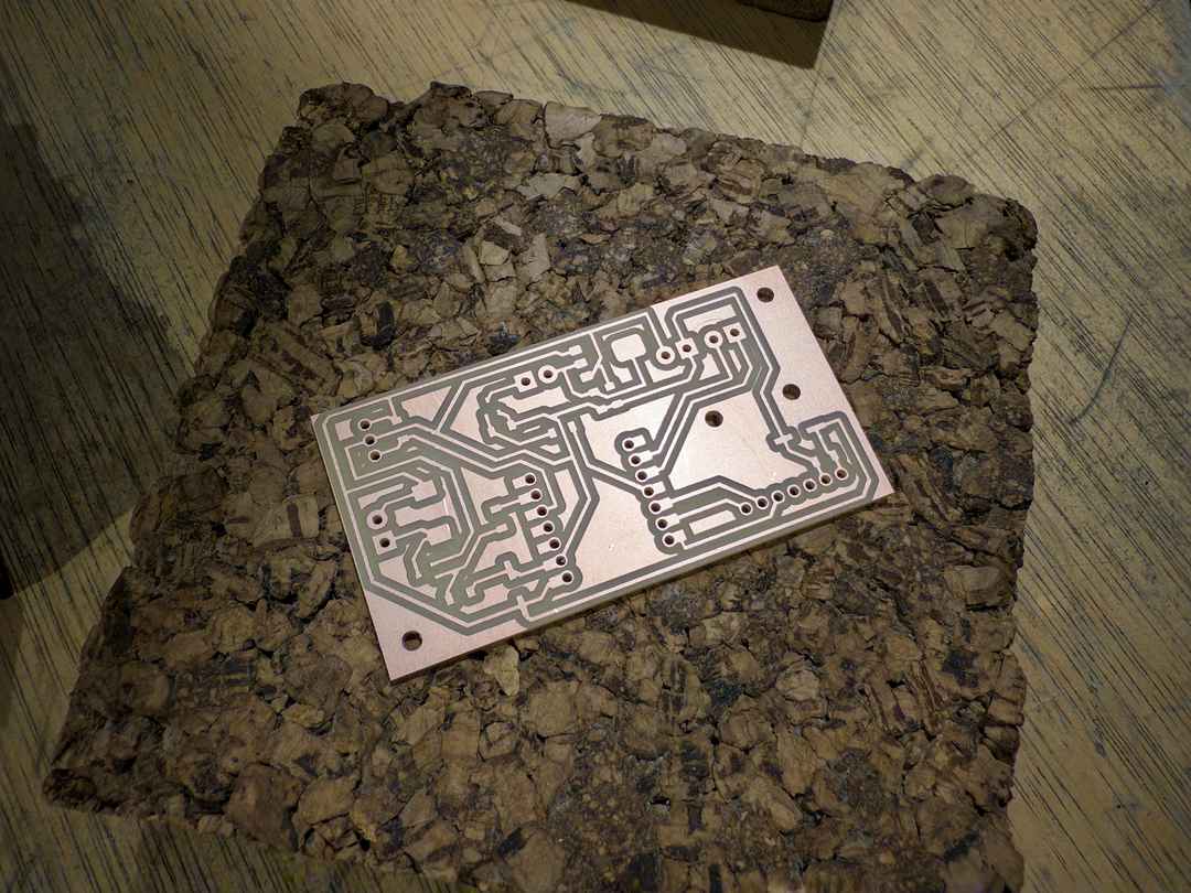
I soldered and populated the board. I used pin headers for the XIAO so it could be removed during testing.
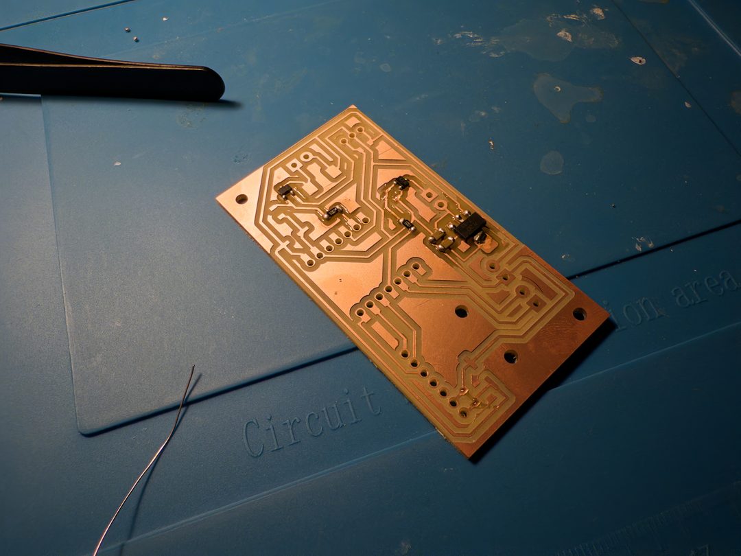
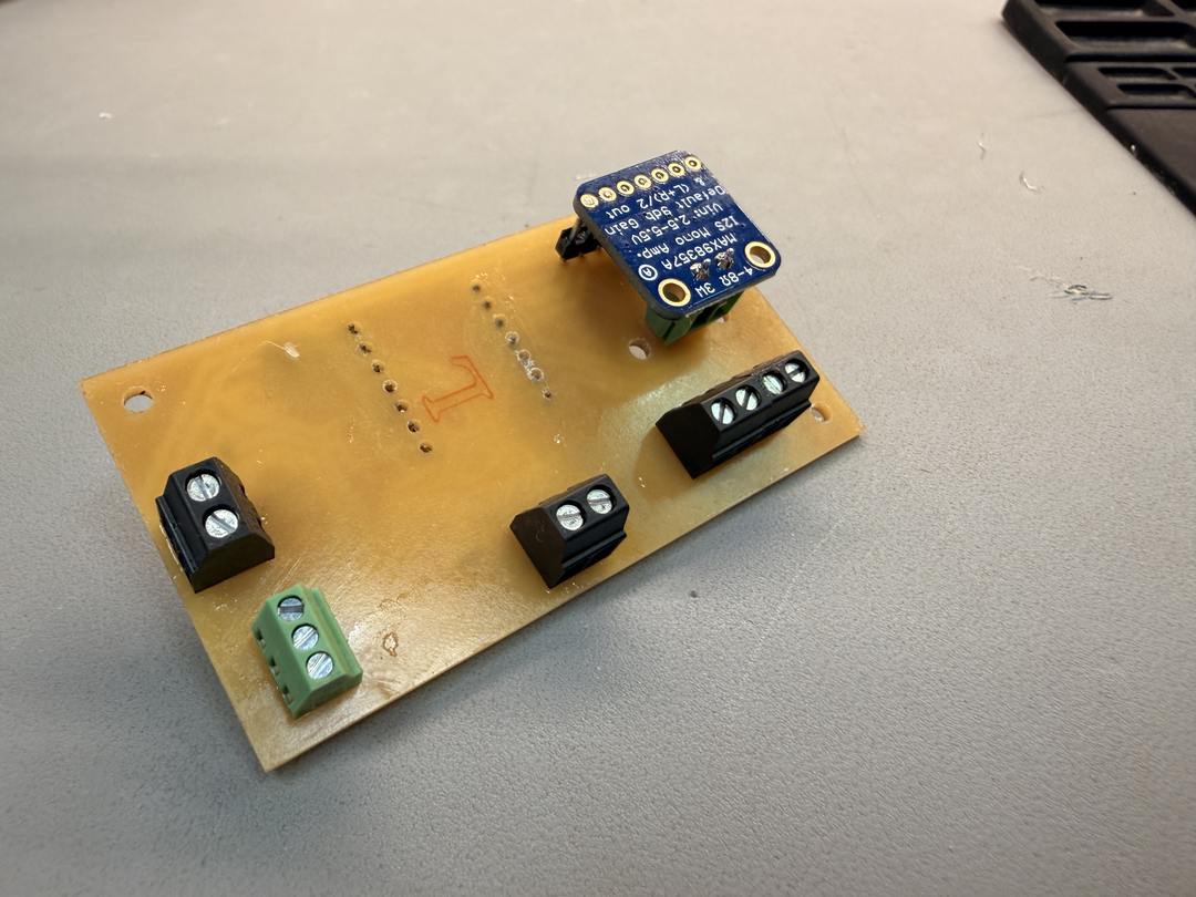
I put all the connectors on the back. Inputs and outputs for the system integration, and easier to solder on a single-sided board.
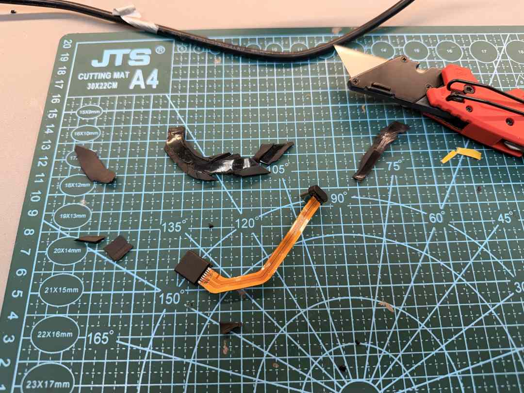
I cut open some USB-C cables to make them more flexible and thinner for the final assembly.
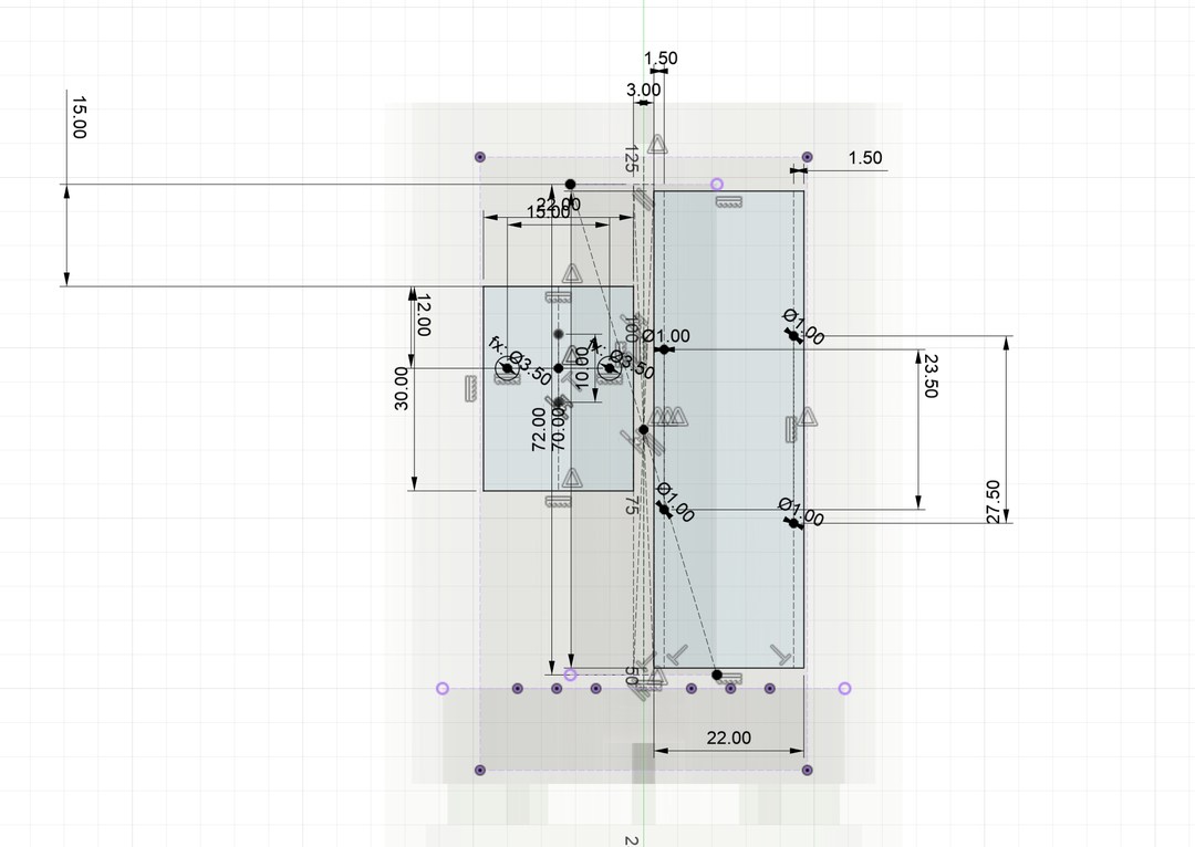
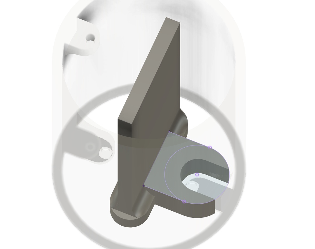
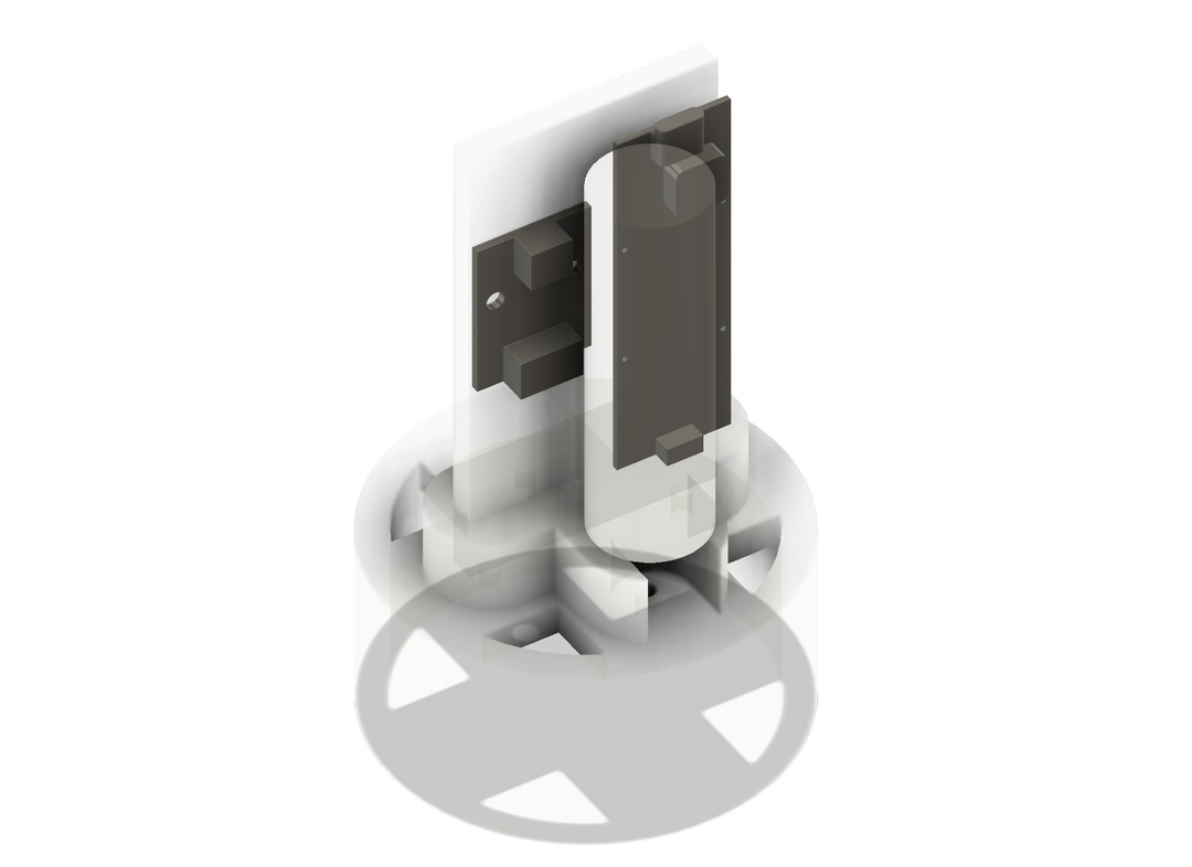
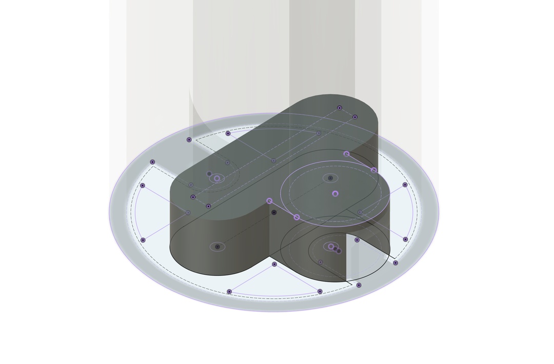
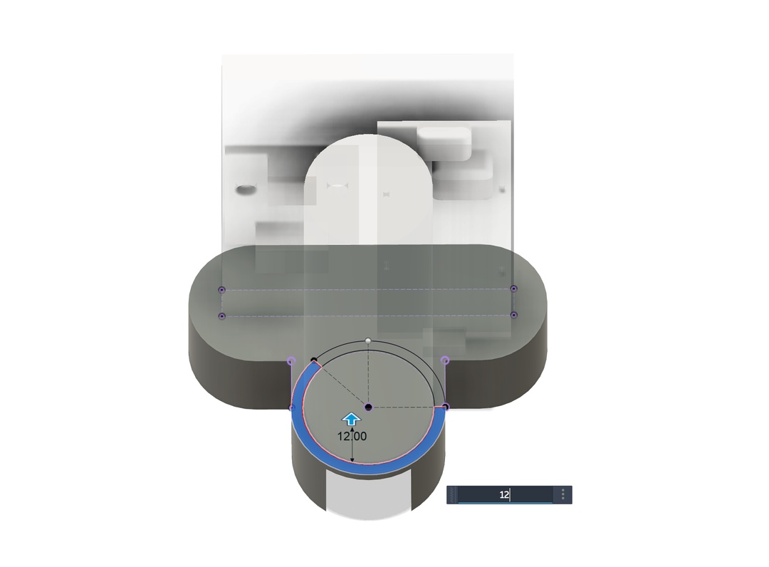
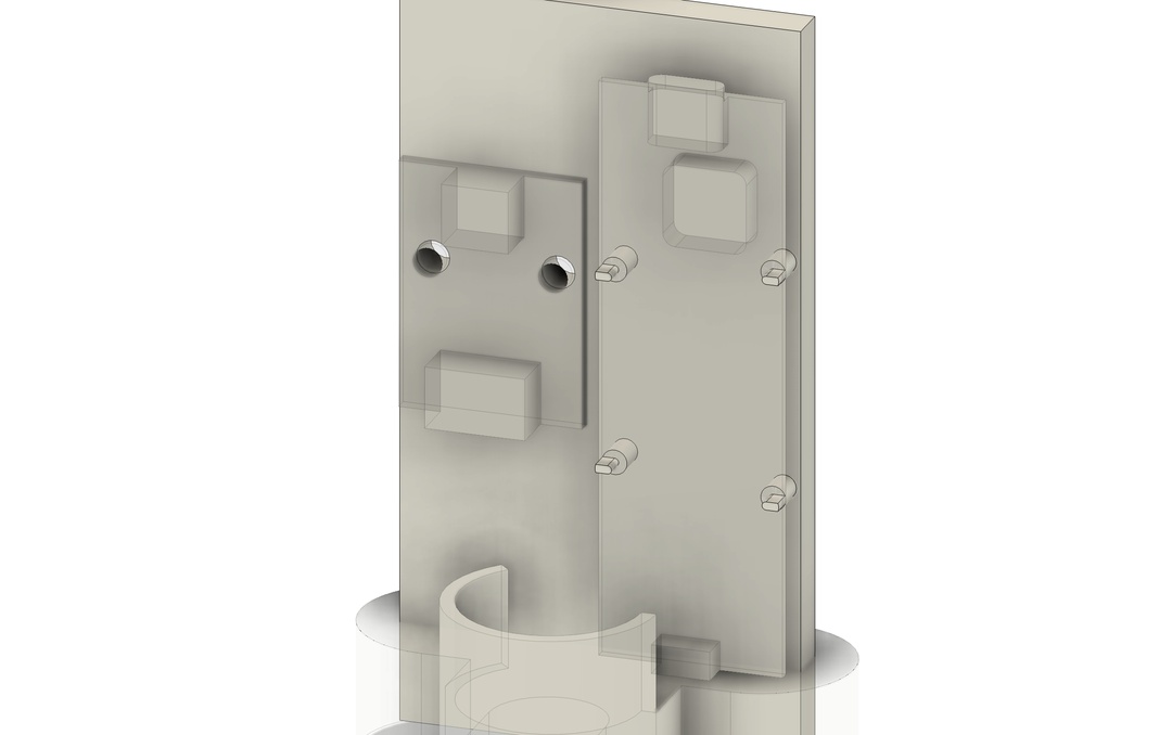
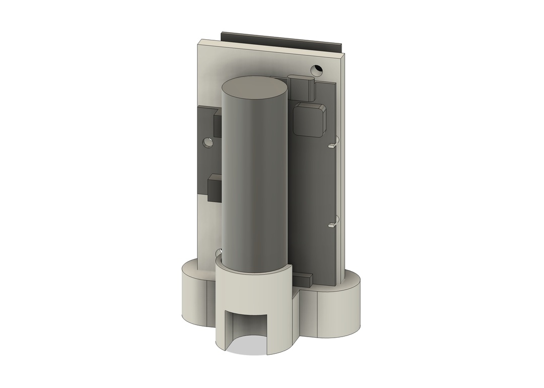
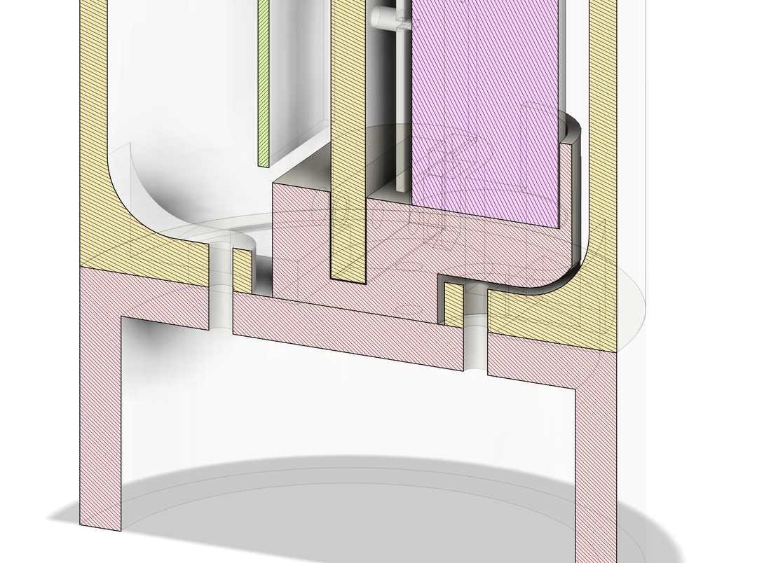
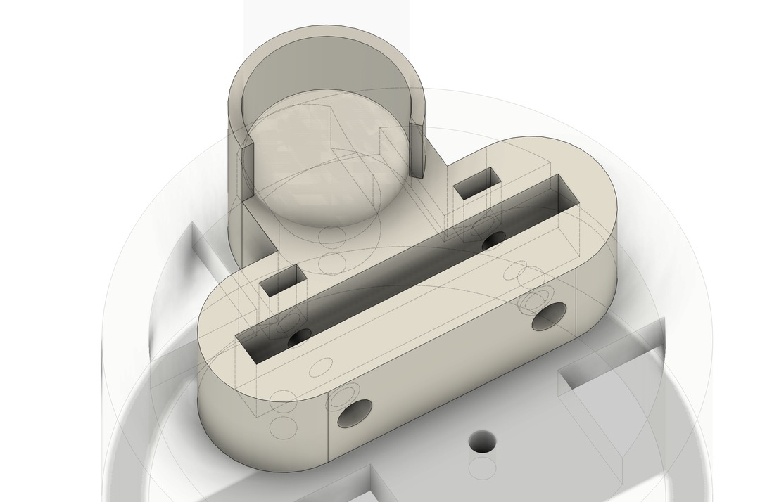
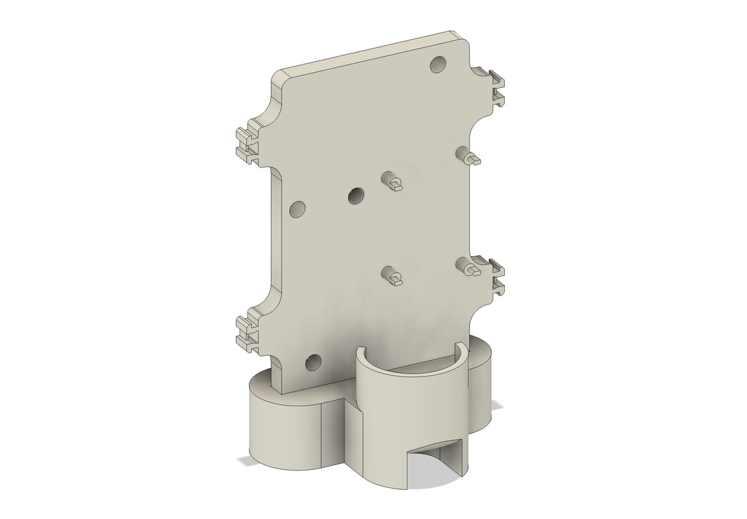
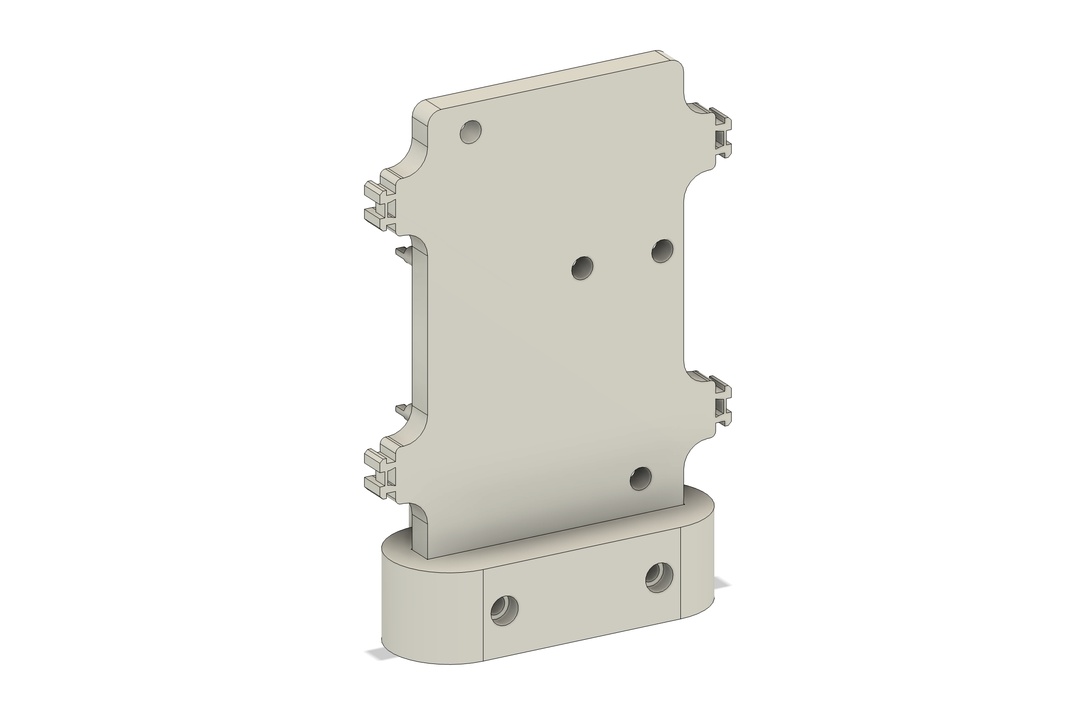
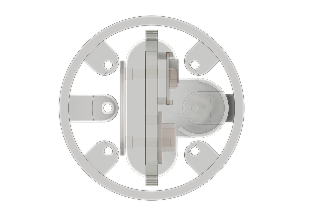
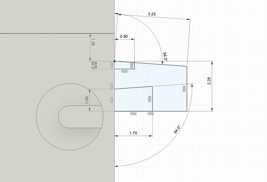
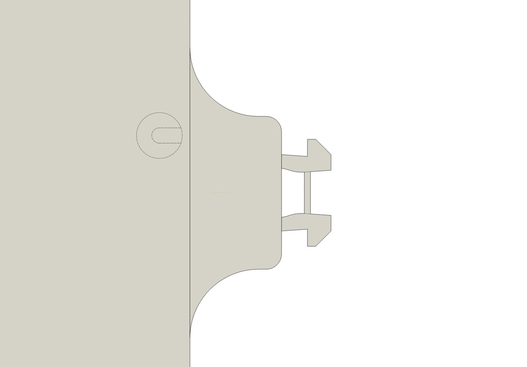
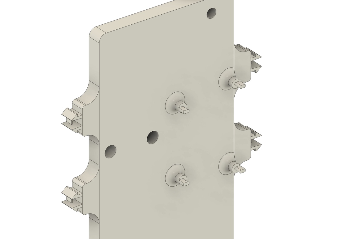
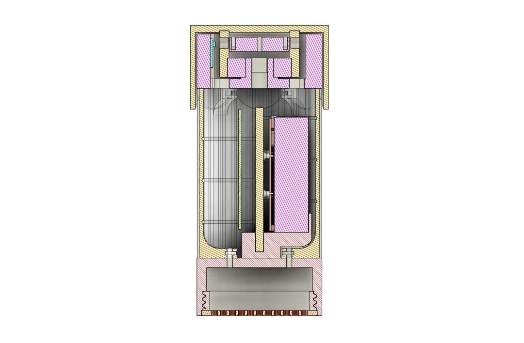
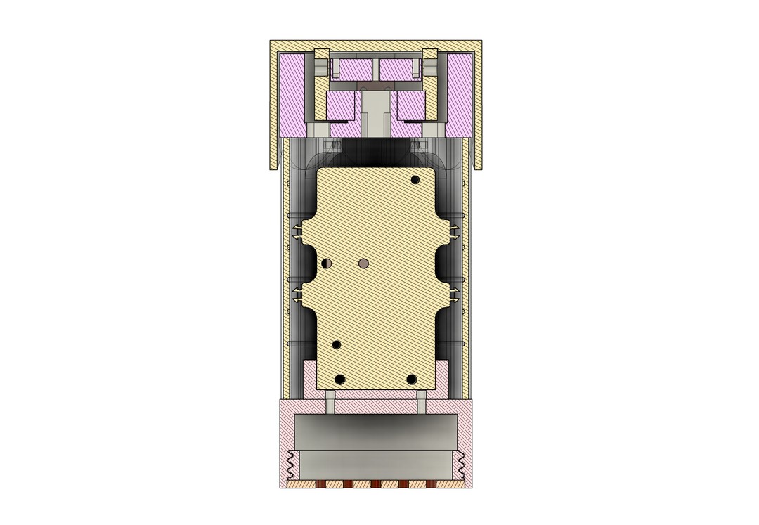
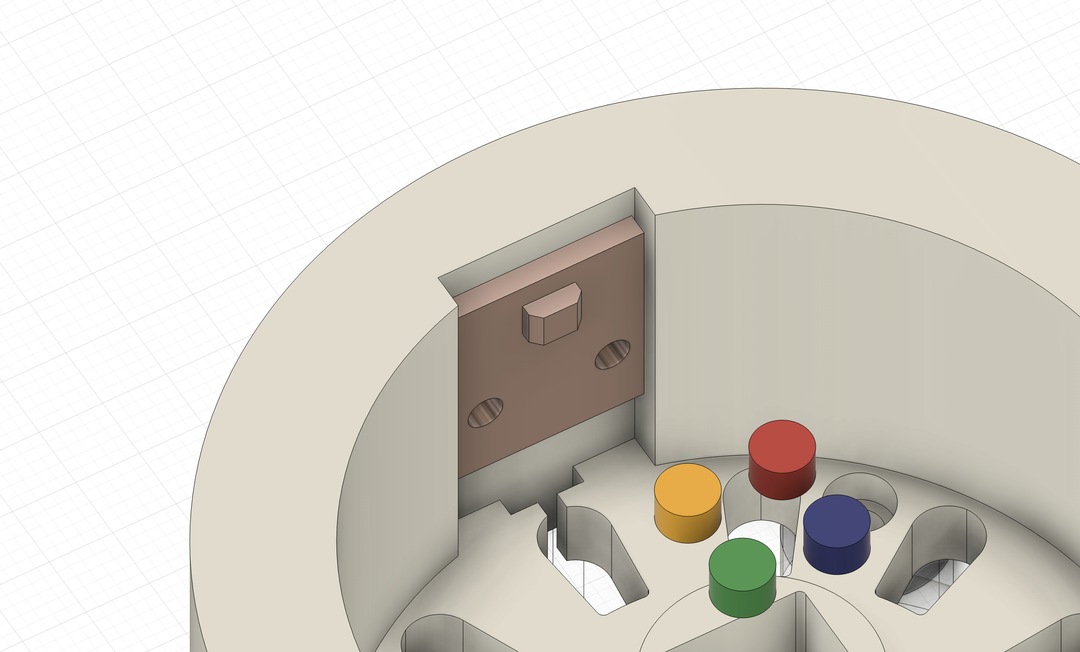
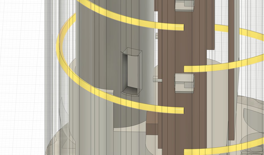
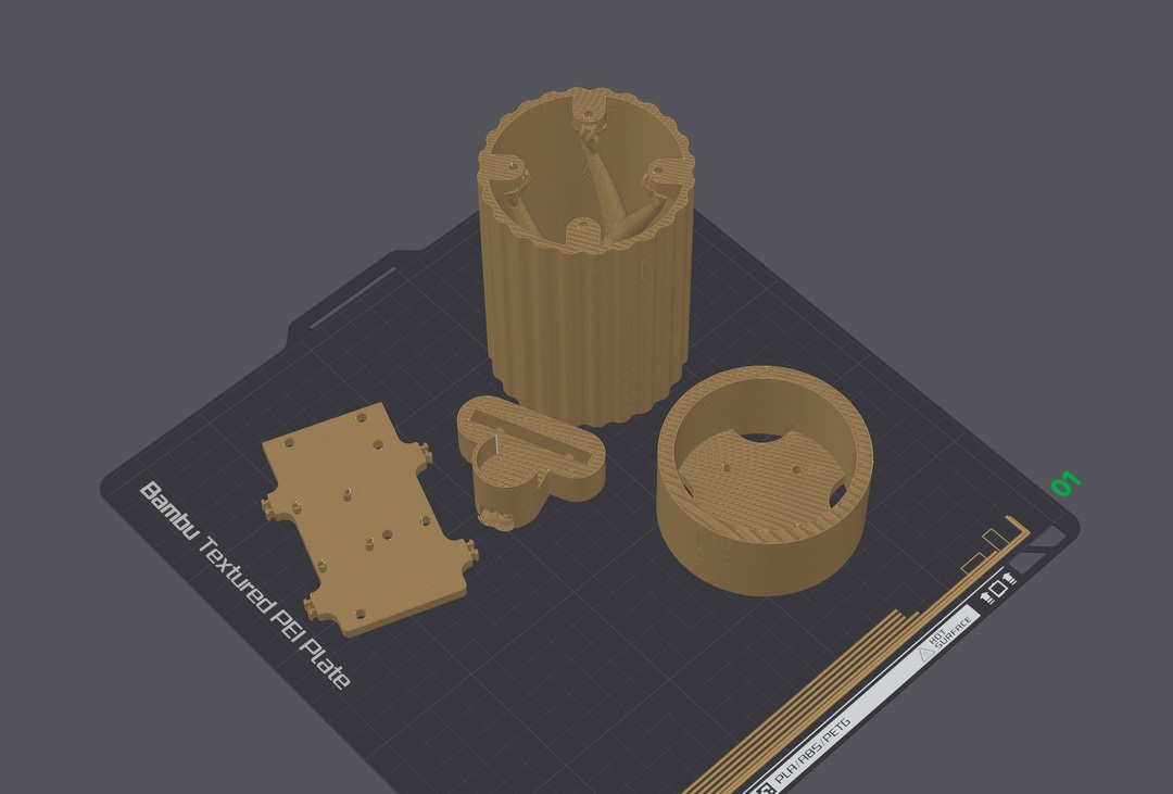
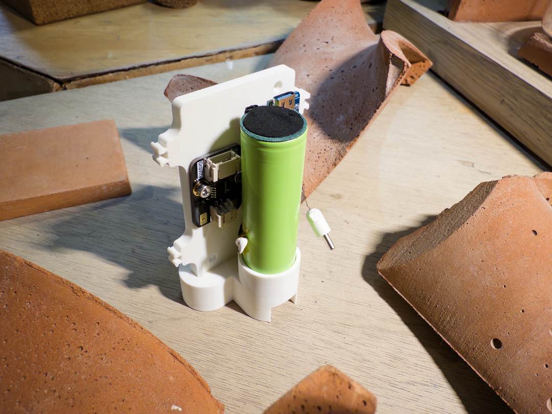
My first electronics mount worked well — tolerances were good and everything mounted correctly, all dimensioned from caliper measurements.
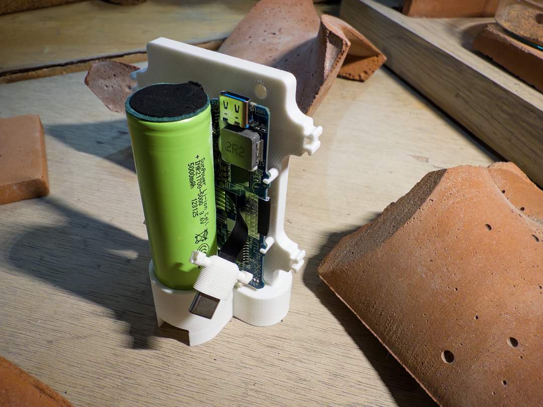
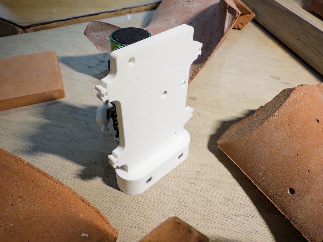
I tested mounting the speaker to the bottom of the object. That worked well too.
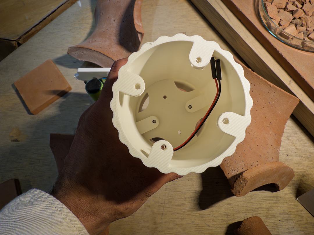
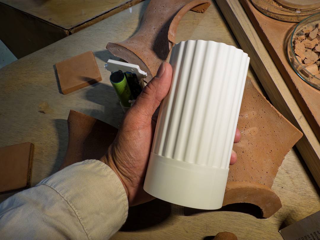
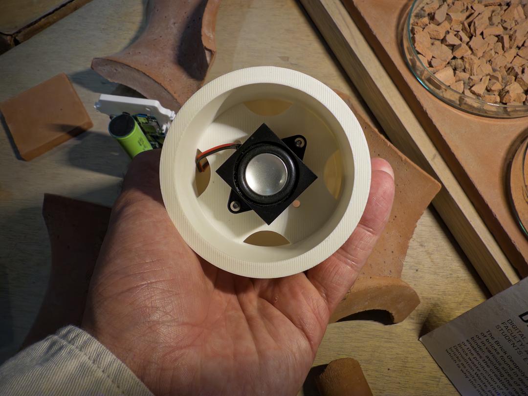
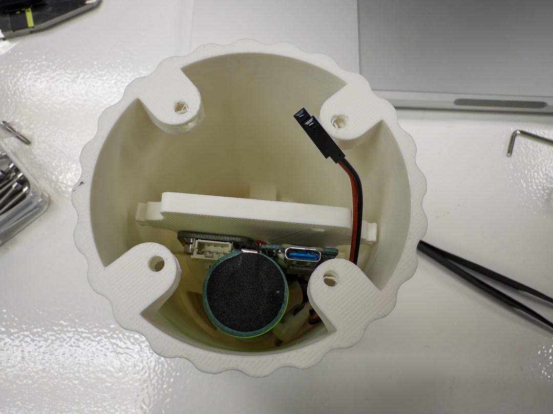
I tested the electronics mount inside the middle section to check the clearance. Tight, but it worked.
I compared using magnets versus nuts for the inner rotor of the magnetic differential.
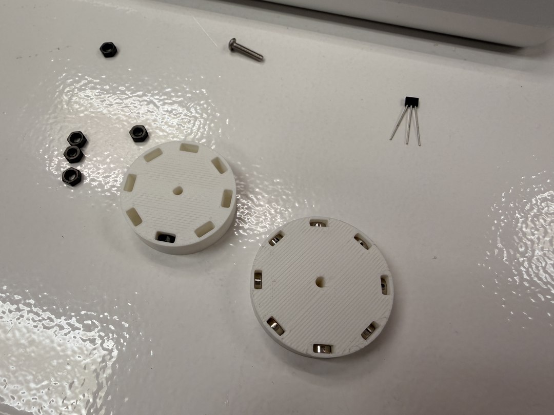
The magnets on both the inner rotor and outer dial were a bit too strong for the magnetic differential slip condition to feel pleasing. The carbon steel nuts on the inner rotor and 5x5 cylindrical magnets on the outer dial had a nice haptic feel.
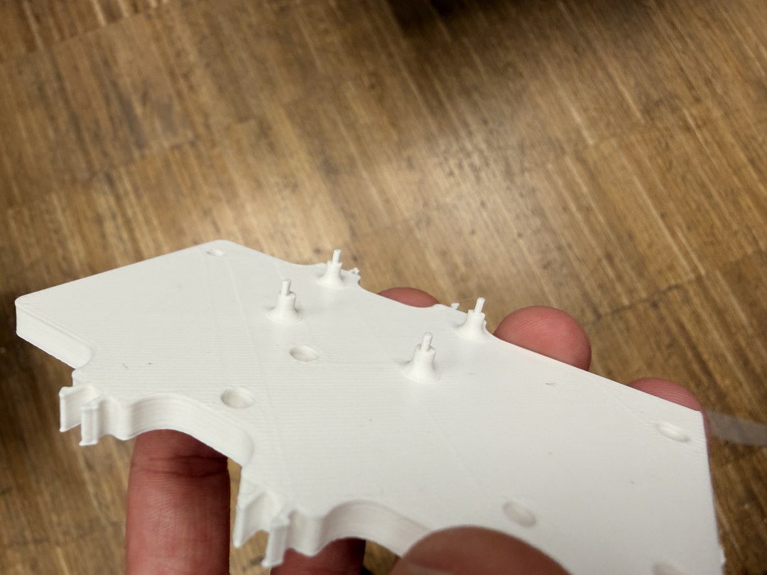
I iterated through several versions of the mount, adjusting the tolerances of the side clips that hold the LED boards.
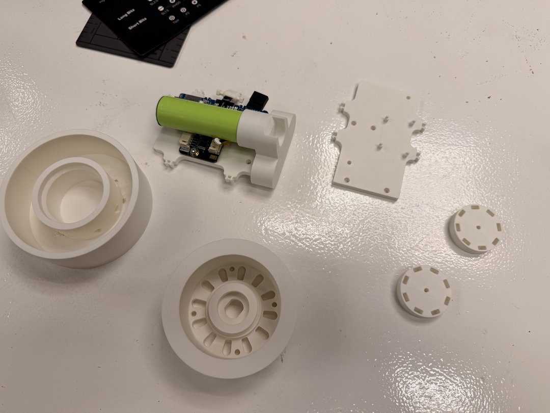
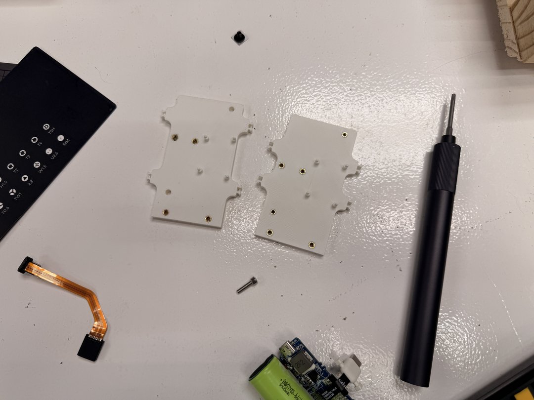
I kept testing LED board fitment alongside each iteration to find the right clip tension and sizing.
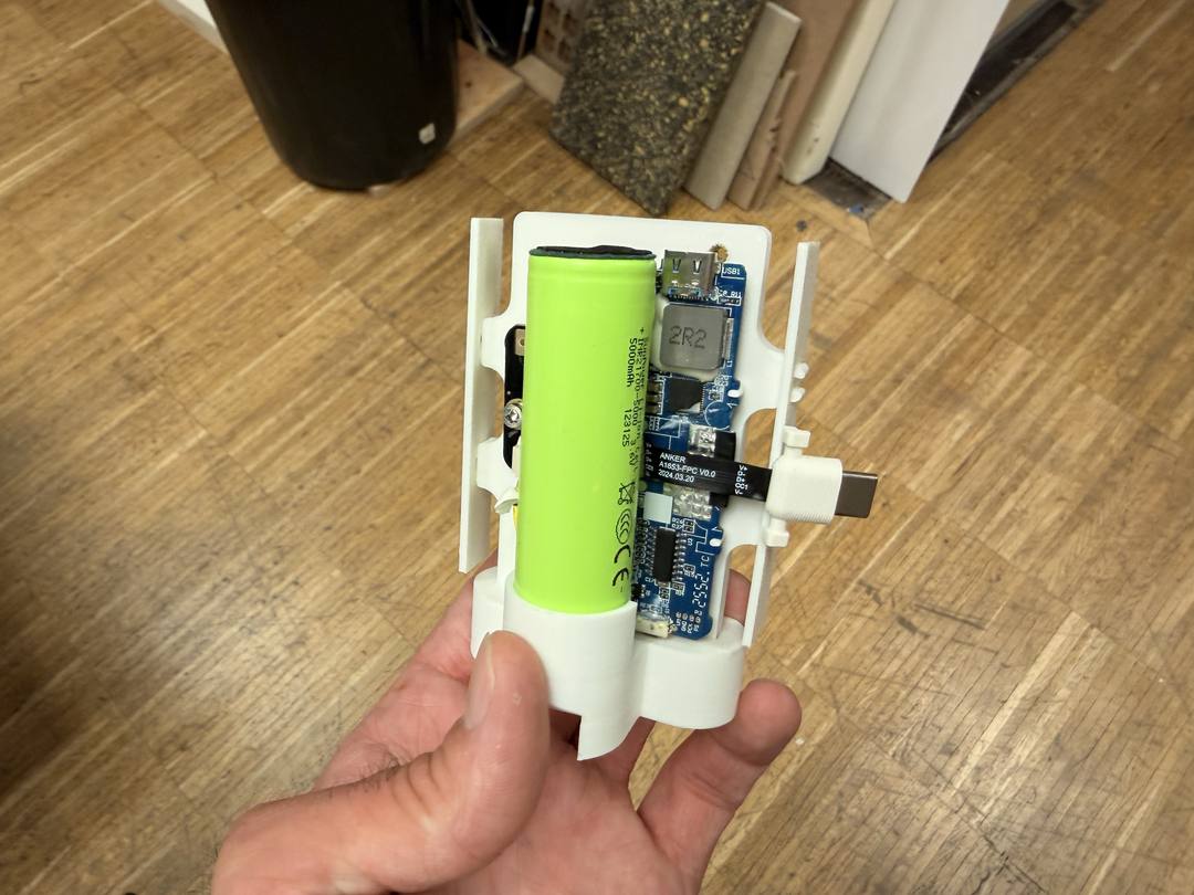
I tried the bicycle headset bearing with my first top assembly design and found it had a little too much friction.
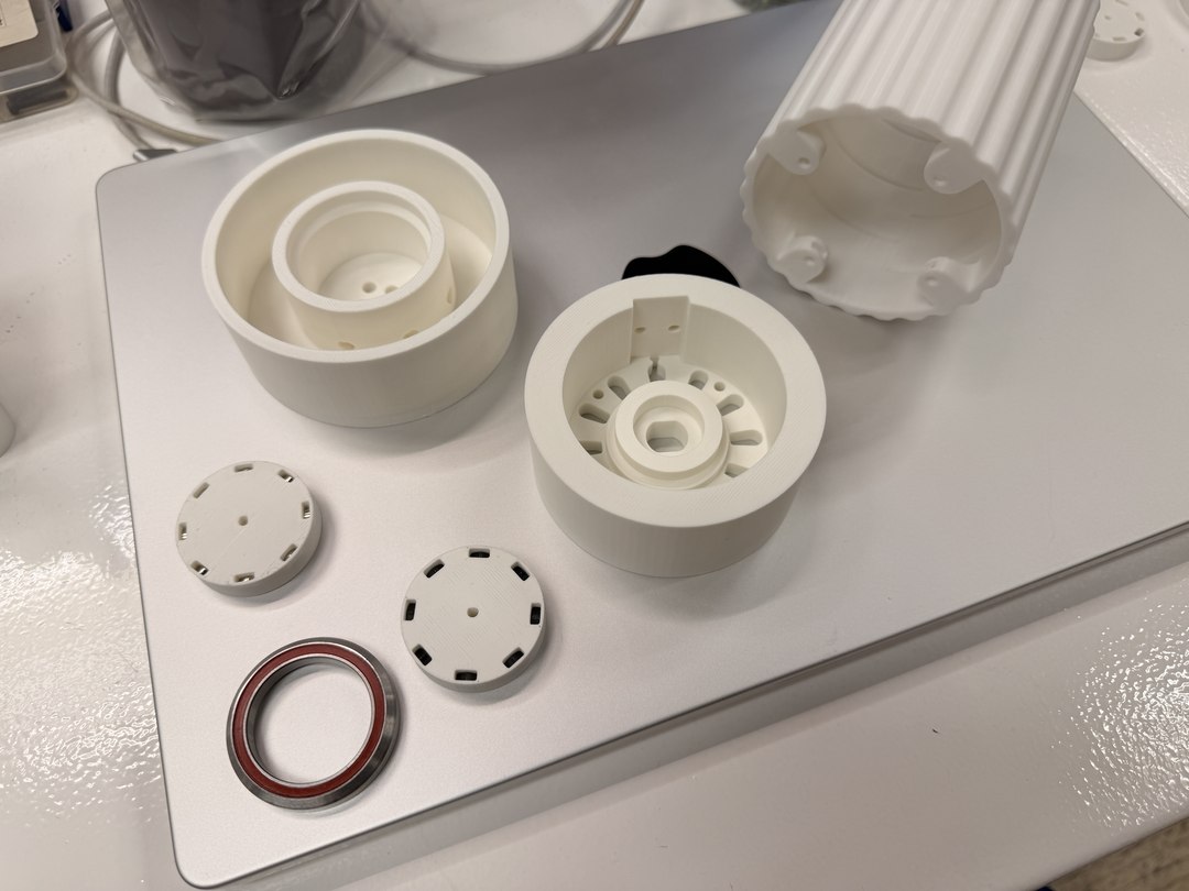
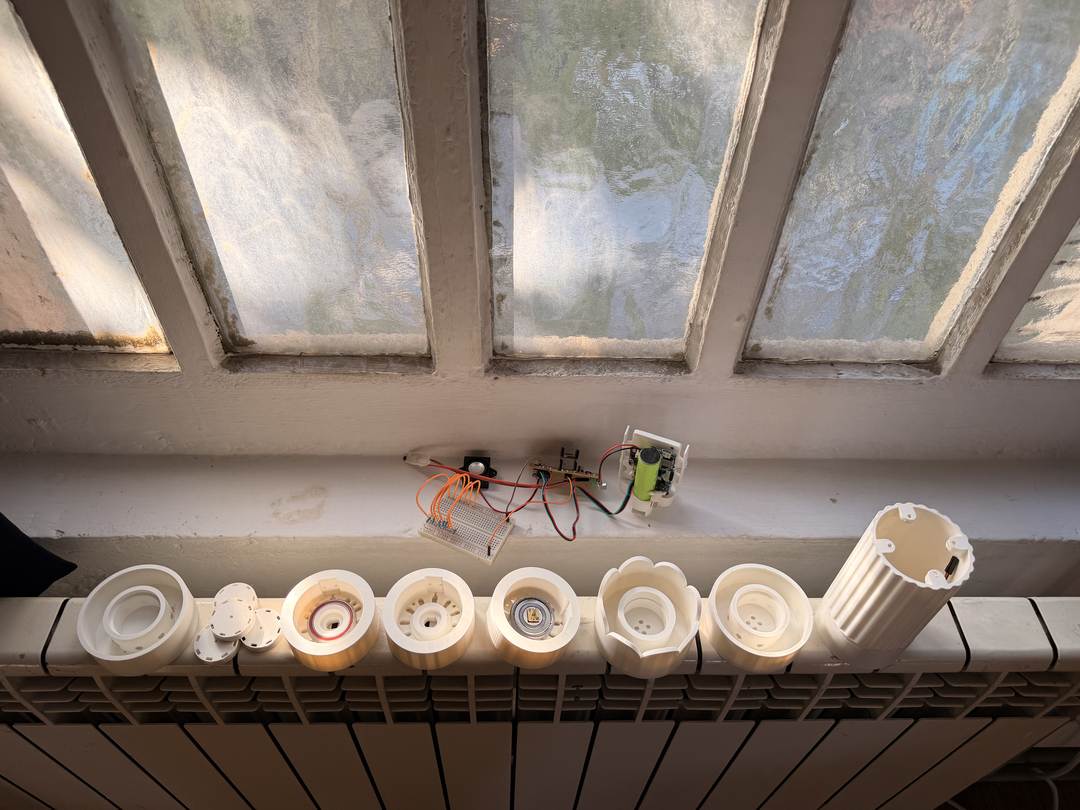
I ended up going back to the larger bearing from my original test dial. It was much smoother with significantly less friction.
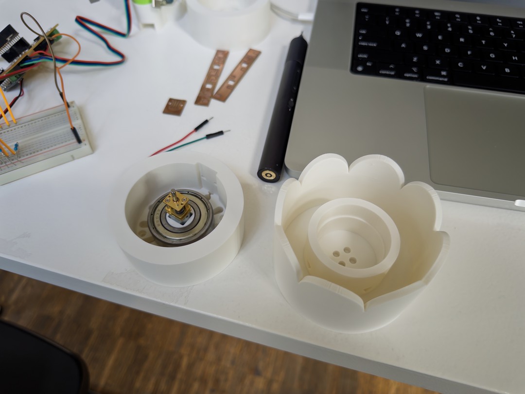
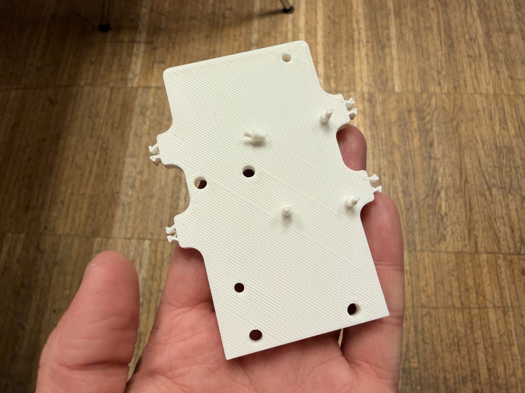
I started having problems with the electronics mount breaking the pins that hold the battery board.
I started SLA printing the top dial and middle section in clear resin. The first top dial was ruined — a clump of supports wouldn't come off cleanly. I tried fixing it with a dremel, but it only made things worse.
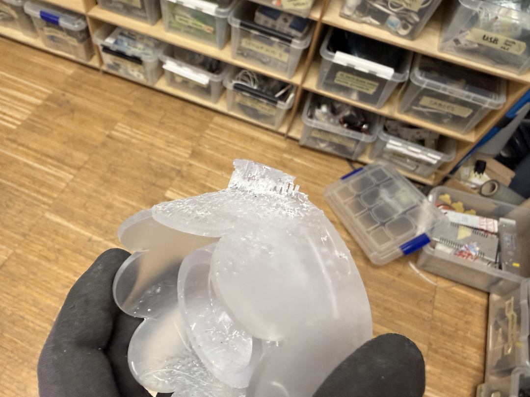
The middle section also had clumps of support on the bottom, but post-processing was easy — a belt sander evened it out to a flat surface.
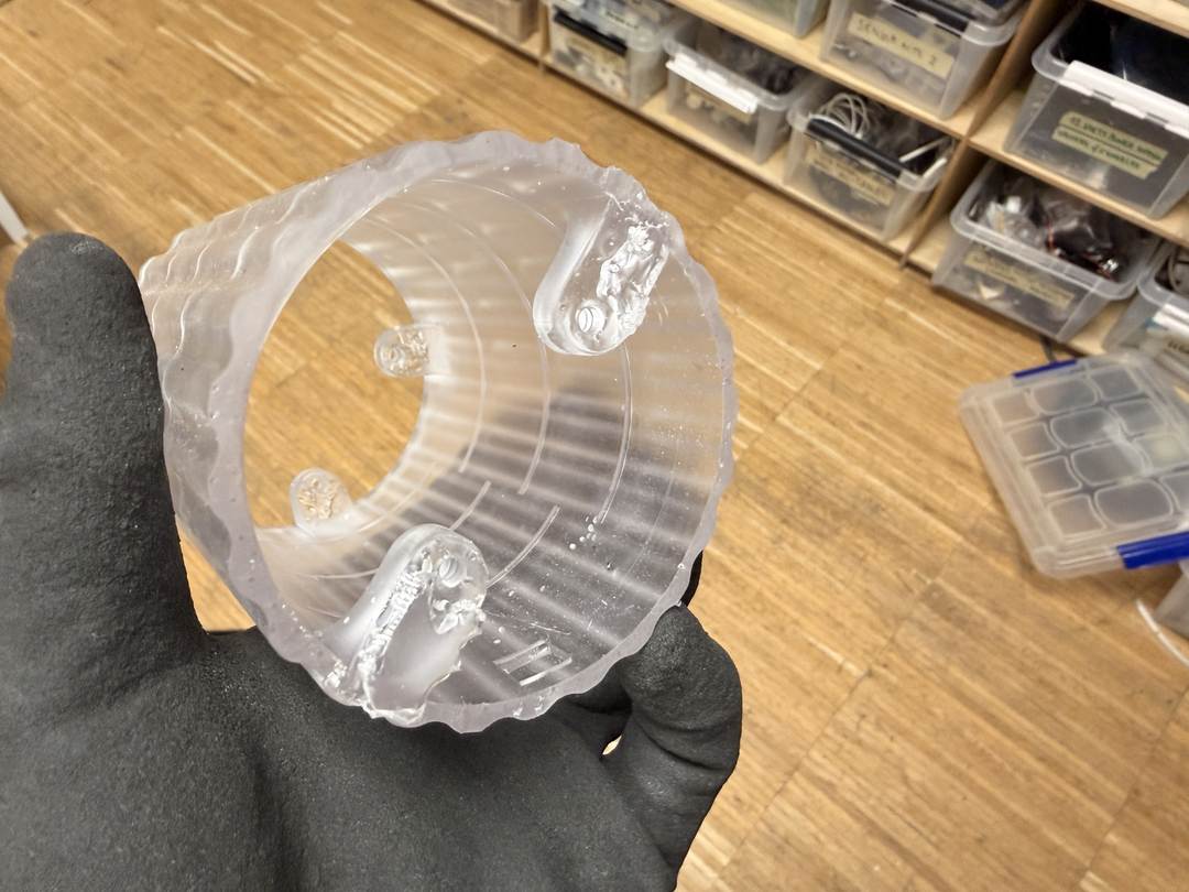
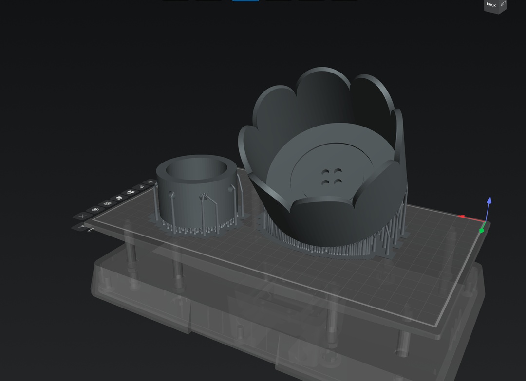
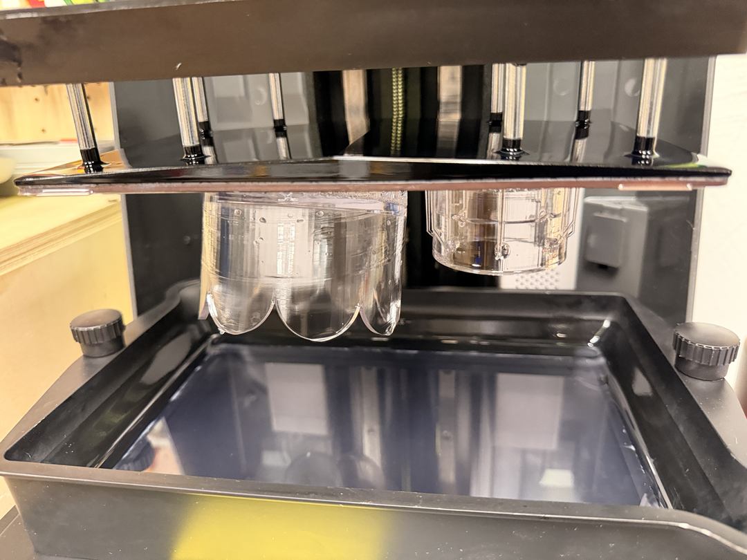
I reprinted the top dial in two parts to get the supports on top instead of underneath. The belt sander smoothed out where the supports had been, and this became the final version.
The firmware for i/o runs on the XIAO ESP32-S3 and was written in C++ for Arduino. It controls all five outputs (LED filaments, motor, LRA haptic, and I2S audio) from a single state machine: IDLE → EXPERIENCE → ENDING → IDLE.
I used AudioTools by pschatzmann for I2S audio and the DFRobot TM6605 library for the LRA haptic driver.
I wrote the full spec for the firmware before writing any code. It described every state, every transition, every piece of output behaviour, the trigger logic, and the timing. I also used the board test sketch as a direct starting point: the confirmed-working ISR pattern, pin definitions, AudioTools I2S setup, TM6605 initialisation sequence, and Hall sensor debounce logic all carried straight in. The individual component tests were the building blocks the final firmware was assembled from, not a blank-slate generation.
IDLE + STARTUP

1. Device is idle.
2. When someone turns the dial, magnets pass by the hall effect sensor.
   Each pulse fires a brief soft LED pulse.
3. The experience doesn't start until 16 pulses (two full rotations).

EXPERIENCE

1. LEDs fade in bright then settle into a slow sine-envelope breathing.
   A gentle long haptic accompanies the fade-in.
2. A gentle ambient tone plays through the speaker, synced to the LED pulse.
3. If the user holds the dial still (motor running, Hall sensor goes quiet),
   the breathing gets brighter and faster, the audio louder.

ENDING

1. Reached when the random timer expires.
2. Long soft haptic fade-in.
3. A soothing tone on the speaker.
4. LEDs increase in brightness then fade out quickly.
5. Motor stops. Device returns to idle.

Experience duration: 30–60 s in test mode, 3–5 min in production.
From that spec, the architecture came out cleanly as three handler functions called from loop(): handleIdle(), handleExperience(), and two one-shot blocking transition functions, enterExperience() and enterEnding().
All the tunable feel parameters (LED brightness ranges, breath speed, dial-held timeout, audio levels, motor duty) live in a separate config.h file. This meant I could adjust feel during physical testing without touching the logic, and the test/production mode toggle is just a single #define TEST_MODE to comment out before final installation.
The breath envelope was one of the key design decisions. Rather than separate timers for LED and audio, both are driven by a single breathPhase float that advances each loop iteration based on elapsed time. sinf(breathPhase) maps to a 0–1 value that drives LED PWM duty and audio amplitude simultaneously, keeping them perfectly in sync with no drift.
The dial-held detection works the same way: a heldBlend float ramps between 0 (normal) and 1 (held) over 800 ms. LED brightness range, breath period, and audio amplitude are all linearly interpolated from this single float, so the transition feels continuous rather than snapping between two states.
// LED driven by blended brightness range
float ledMin = LED_BREATHE_MIN + heldBlend * (LED_HELD_MIN - LED_BREATHE_MIN);
float ledMax = LED_BREATHE_MAX + heldBlend * (LED_HELD_MAX - LED_BREATHE_MAX);
ledcWrite(PIN_LED_PWM, (uint8_t)(ledMin + breathVal * (ledMax - ledMin)));

// Audio follows the same heldBlend
float audioFloor = AUDIO_NORMAL_FLOOR + heldBlend * (AUDIO_HELD_FLOOR - AUDIO_NORMAL_FLOOR);
float audioRange = AUDIO_NORMAL_RANGE + heldBlend * (AUDIO_HELD_RANGE - AUDIO_NORMAL_RANGE);
sine.setAmplitude((int16_t)(audioFloor + breathVal * audioRange));
One constraint with AudioTools that shaped the architecture: the I2S DMA buffer has to be kept fed by calling copier.copy() frequently. If you block in a delay() for more than a few milliseconds, the audio cuts out. Every blocking sequence in enterExperience() and enterEnding() runs inside a while loop that calls copier.copy() on each iteration instead of using delay().
The Hall sensor ISR is kept minimal: IRAM_ATTR, debounced via microsecond timestamps, sets a single volatile bool pulseFlag and returns. The flag is consumed in the appropriate state handler each loop so no processing happens inside the interrupt.
The most interesting bug I found during testing was with the TM6605 haptic driver. The haptics weren't working and the serial monitor showed TM6605 failed on every boot. It turned out the init check was inverted: TM6605.begin() returns 0 on success, but the loop condition was while (!TM6605.begin()), which means the loop ran forever when the device was working fine, and exited immediately when it failed. The haptic driver had been working all along. Fixing it to while (TM6605.begin() != 0) was a one-character change.
I set up OTA (over-the-air) uploads early on because the object is assembled and I can't reach the XIAO via USB once it's inside the enclosure. A reusable wifi_ota.h header handles connecting to either of two WiFi networks on boot and makes the board available as a wireless upload target in Arduino IDE. Every sketch in the repo includes it.
When I ran into issues during assembly and couldn't tell which component was at fault, I wrote targeted diagnostic sketches to isolate the problem. A no-audio version of the main sketch removed all AudioTools code to test LED, motor, and haptic in isolation. A shutdown sketch immediately stops all outputs on boot, useful for safely parking the device before a re-upload. A motor and Hall sensor test replaced serial output with LED flashes, one flash per magnet pass, since I only had OTA access and no serial monitor.
The code was written using Claude Code (the CLI tool). The test sketches were the starting material: I provided the confirmed-working Hall sensor ISR, the TM6605 initialisation sequence, the LED PWM setup, the I2S AudioTools configuration, and the haptic breathe pattern as inputs to the session. The firmware wasn't built entirely from scratch, it was assembled from those earlier pieces, with me specifying how they should connect: the states, the transitions, the behaviour of every output in each state, and the feel I was after. I'd upload a new version, run it on the device, describe what was wrong or off, and direct the next fix. The architecture, the design decisions, and the direction of every revision came from me. The code is AI-generated.
This was the same process I used for the week 11 firmware. The spec I wrote before starting is shown above: that's the brief I gave at the beginning of the session, and the architecture that came out of it stayed intact through every revision.
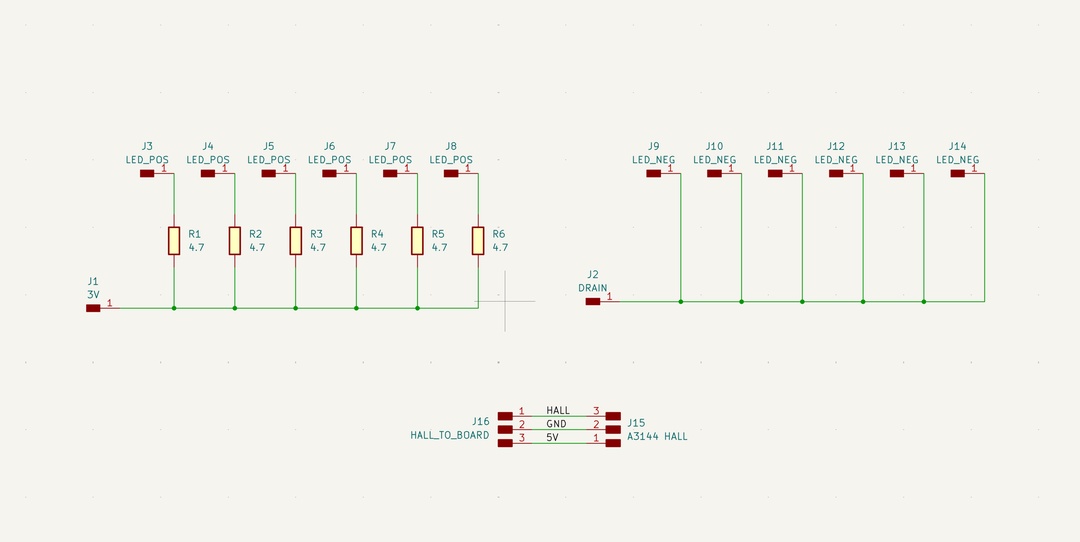
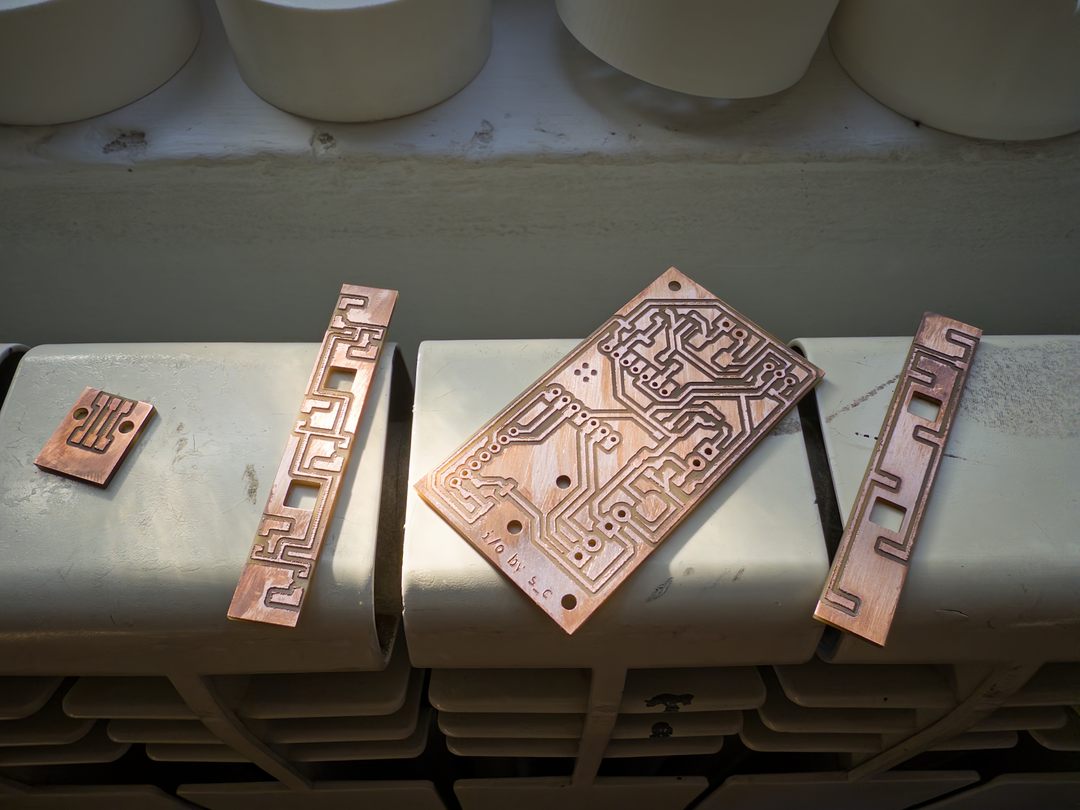
I milled all four final boards in one run: the main i/o board, the hall effect sensor board, and two LED boards.
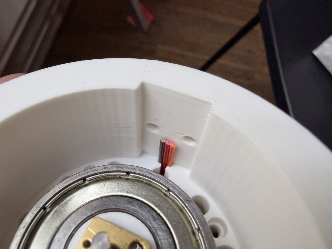
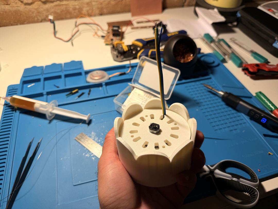
I tested running the hall effect sensor wiring through the top piece of the enclosure.
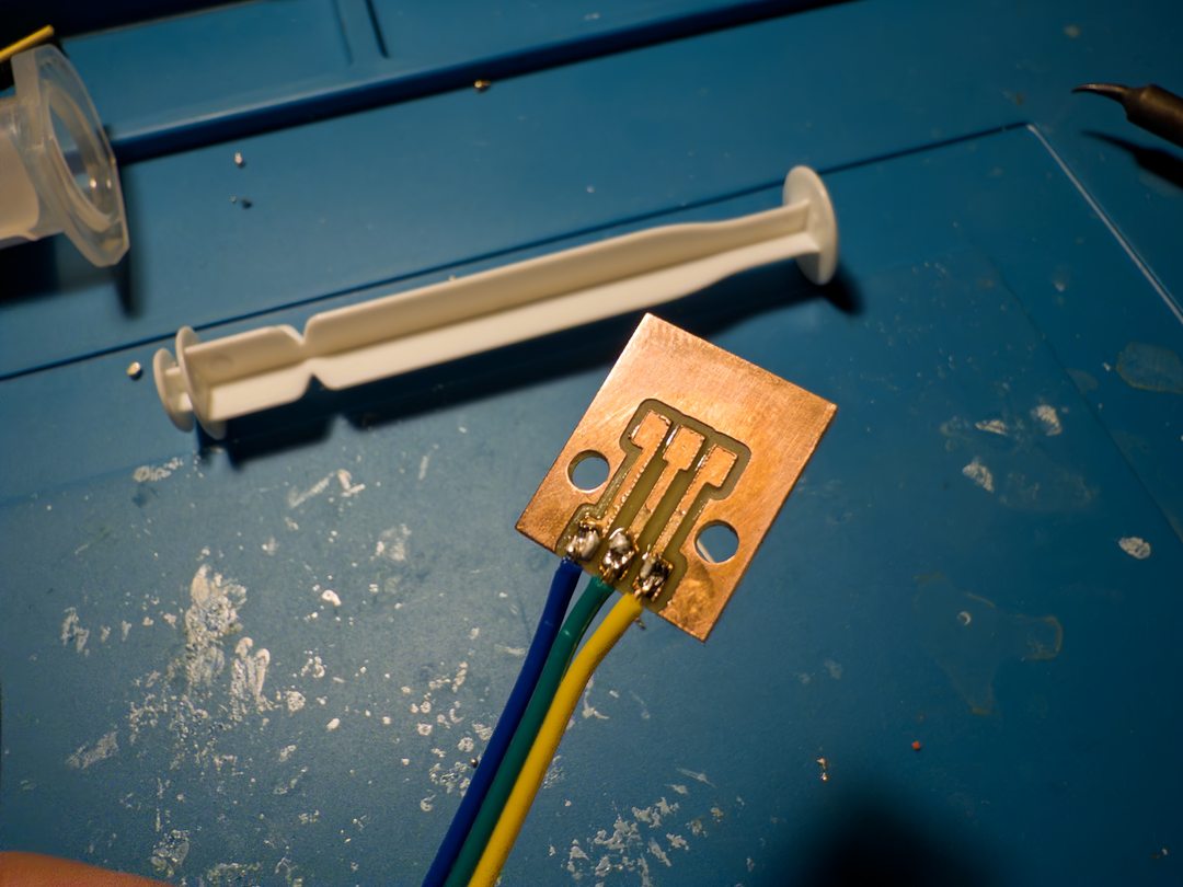
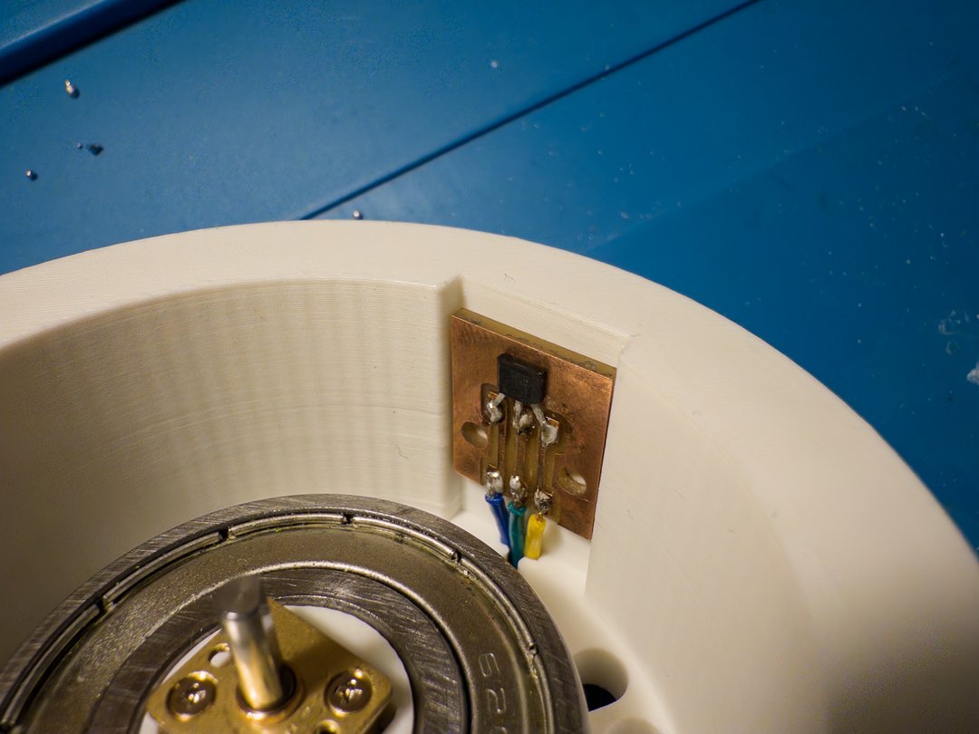
I soldered the wires onto the hall effect sensor board.
I bent the hall effect sensor legs to get them to the correct pitch of my board I designed.
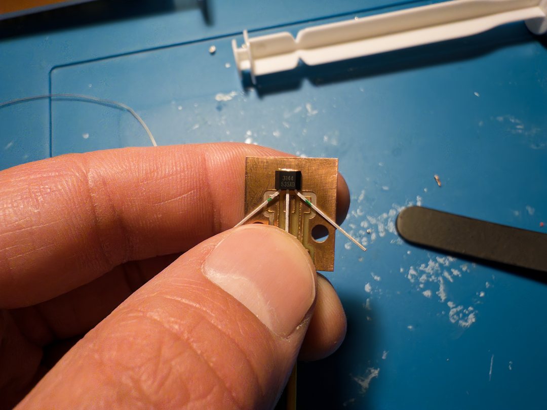
I then marked where to cut the sensor legs so it would fit on the board.
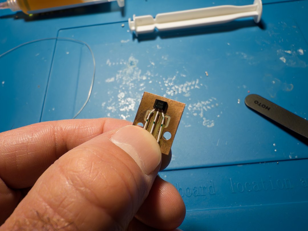
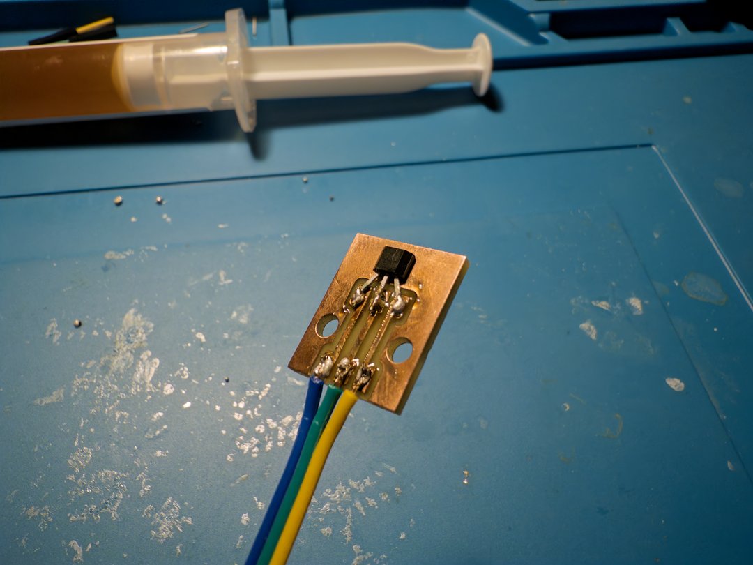
The final i/o board was much cleaner and slimmer.
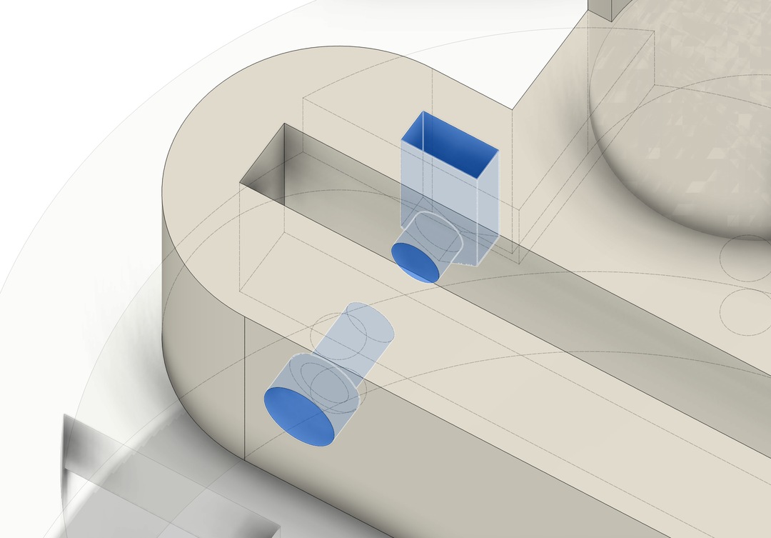
I added fillets to the tabs on the electronics mount that clip into the battery board so that they wouldn't break as easily.
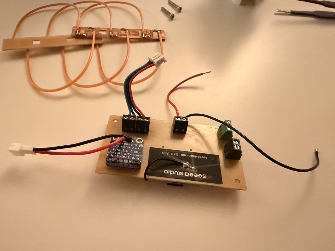
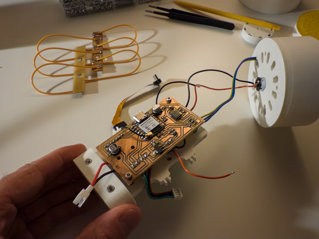
The back of the assembled board, with the input/output wires in their terminals and the XIAO WiFi antenna stuck to the back. You can see the LED boards with flexible filaments assembled in the background.
I mounted the hall effect sensor board on the top piece of the enclosure, next to where the dial sits.
I fitted the inner rotor with the steel nuts and seated it inside.
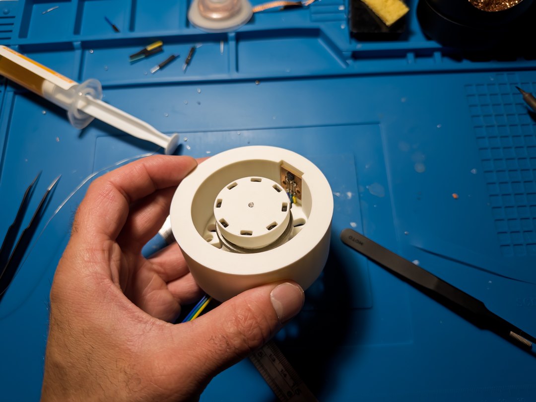
I did a test assembly of the top section with a placeholder dial (not the resin one) just to check everything fit.
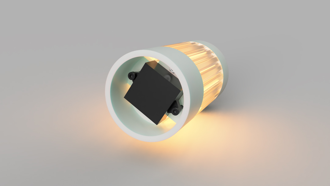
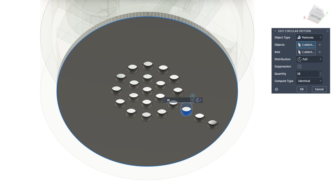
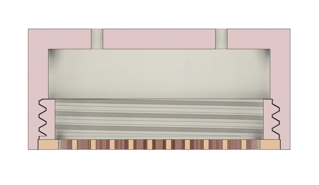
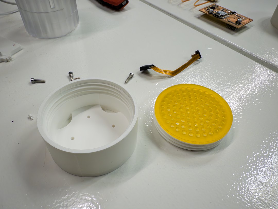
Here's the screw mounted speaker grille that goes on to bottom to hide the speaker and give the base a cleaner finish.
I mounted the i/o board on the electronics mount with all the input and output wires in their screw terminals.
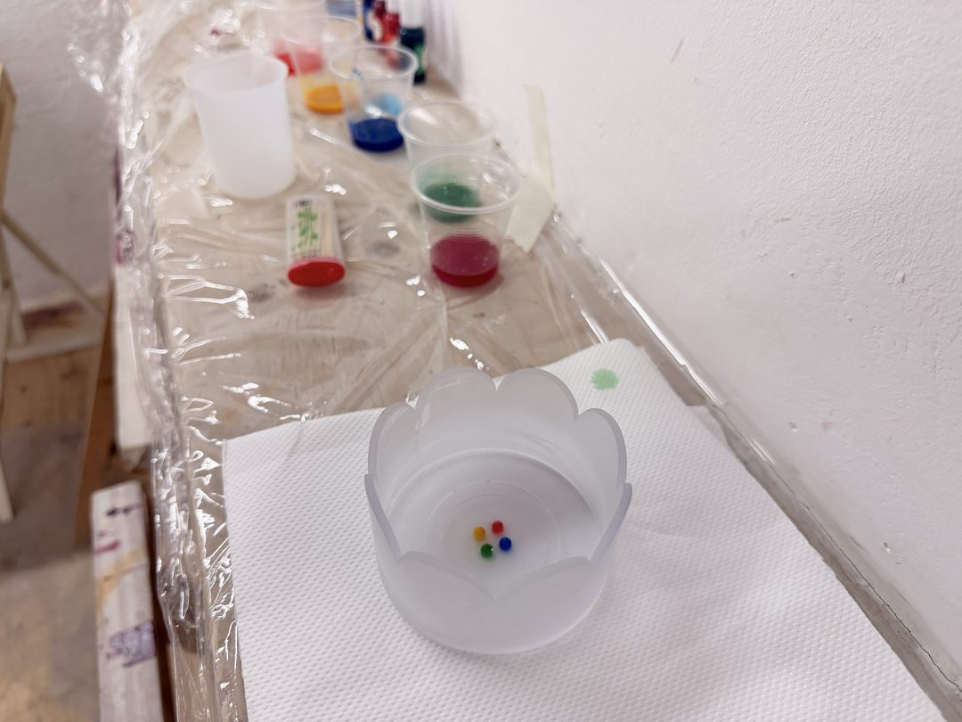
I mixed epoxy resin, separated it into four small containers, and dyed it the colours of my logo. I then cast it into the logo cavity I extruded into the design of my clear resin-printed top dial.
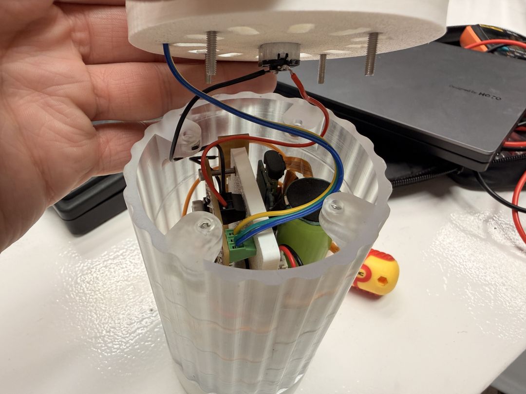
Here you can see under the hood (the top section), to show everything mounted inside.
Here's a bonus direction I explored. The concept was loose, but the core idea is a multimodal alarm clock that uses light, sound, and touch together. The time display is hidden behind a distortion grill: you can't just glance at it. You have to pick it up and wrestle with it to read the time or turn off the alarm. That friction is intentional. It also prevents you from glancing at the time while you're trying to sleep (that's the worst).