For this week's assignment, I decided to explore ways to veil an alarm clock display in order to allow the user to choose when they want to view the time.
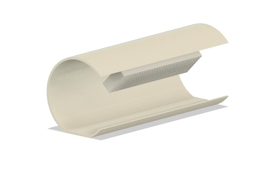
I wanted to use a geometry that would allow someone to see the display when viewed from a specific angle and would only allow distorted or diffuse light through from the display at other angles.
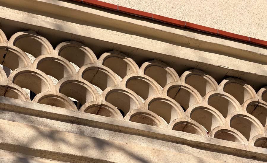
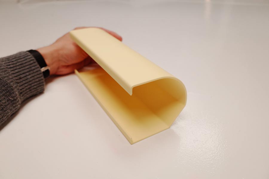
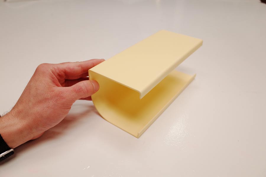
While walking by some scalloped breezeblocks, which are commonly found on balconies in Barcelona, I suddenly realized that this would be an interesting geometry to create the effect I wanted.
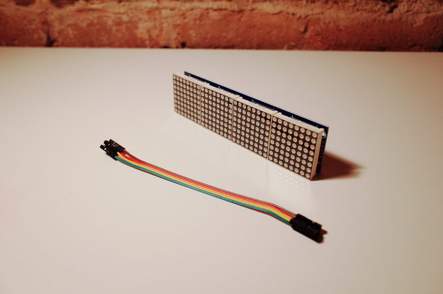
I got a MAX7219 dot matrix display for it's bright warm LEDs, to get the effect I desired. I was planning on designing an alarm clock circuit board for Week 06: electronics design.
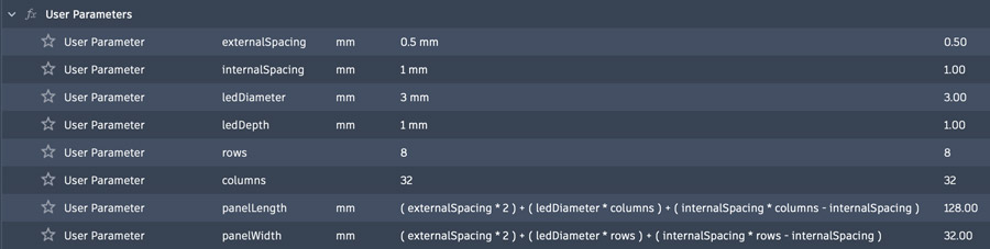
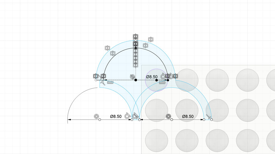
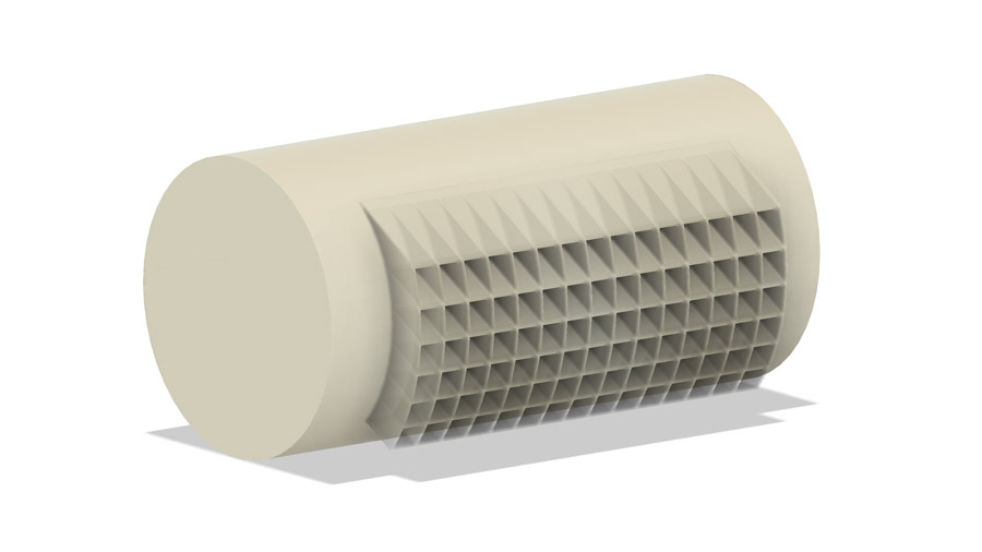
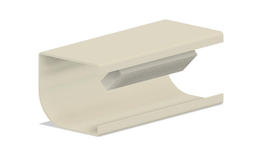
The first step I took was to design a model of the MAX7219 got matrix display so that I could accurately model the veil. I designed it to be modified parametrically, so that I could change the number of rows and columns of LEDs if needed.
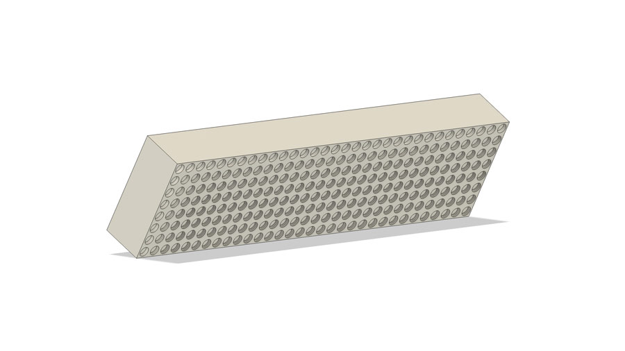
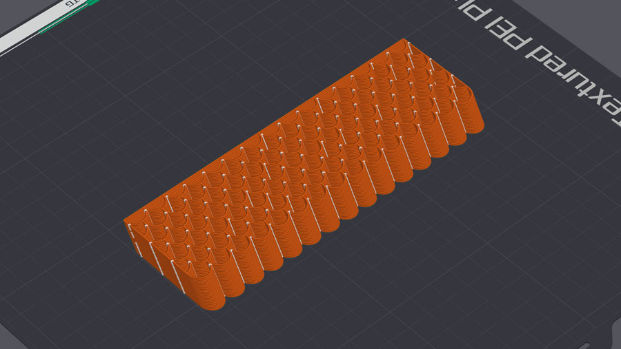
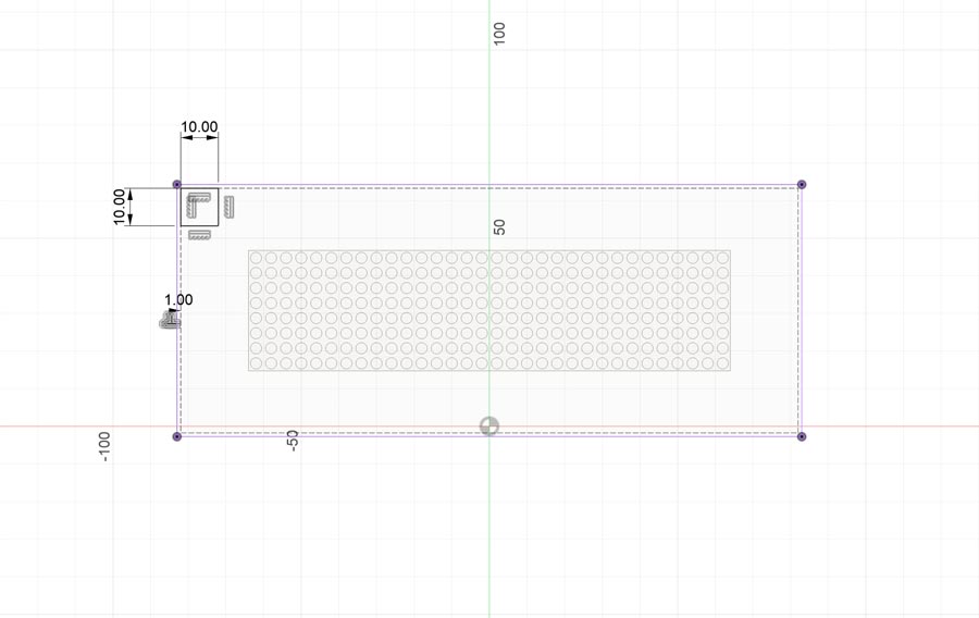
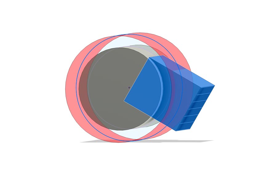
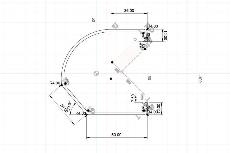
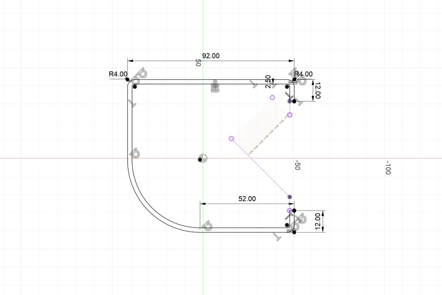
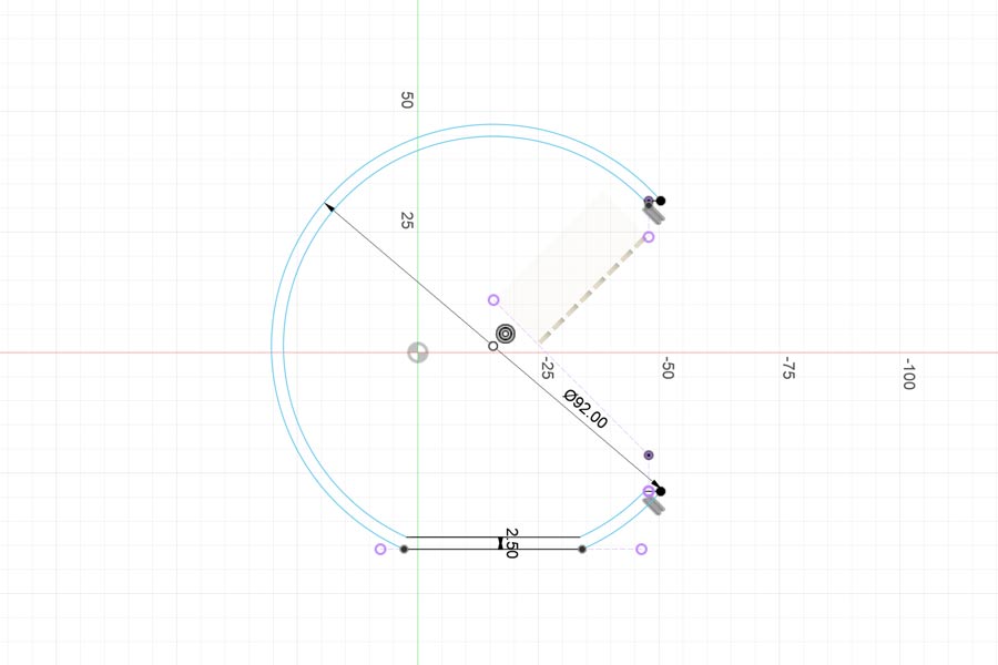
By referencing the spacing of the LEDs of the display I created a sketch of the scalloped pattern I wanted to use for the veil.
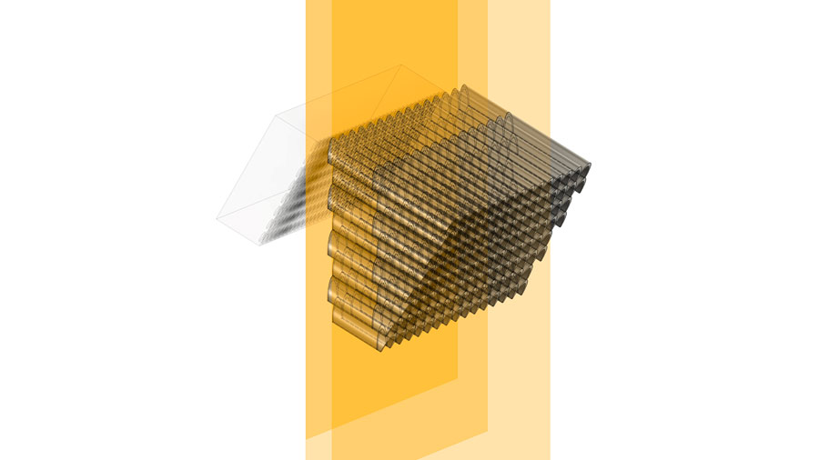
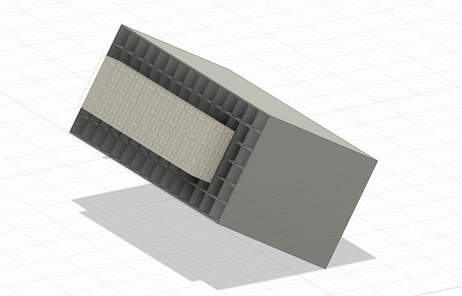
By extruding that one pattern instance, I could then use the rectangular pattern to set the width and height of the veil. I extruded this pattern instance from an offset plane parallel to the face of the display, which was sitting at an angle.
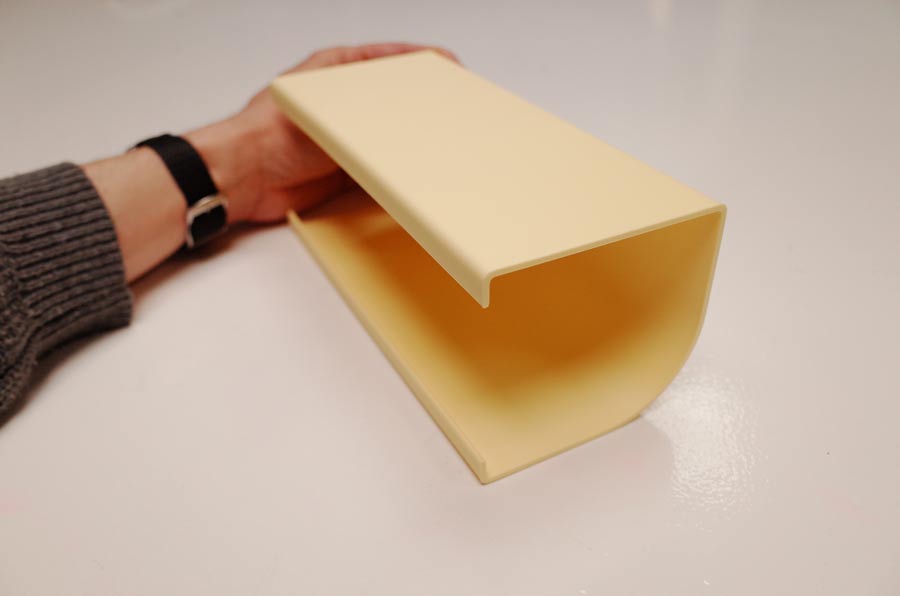
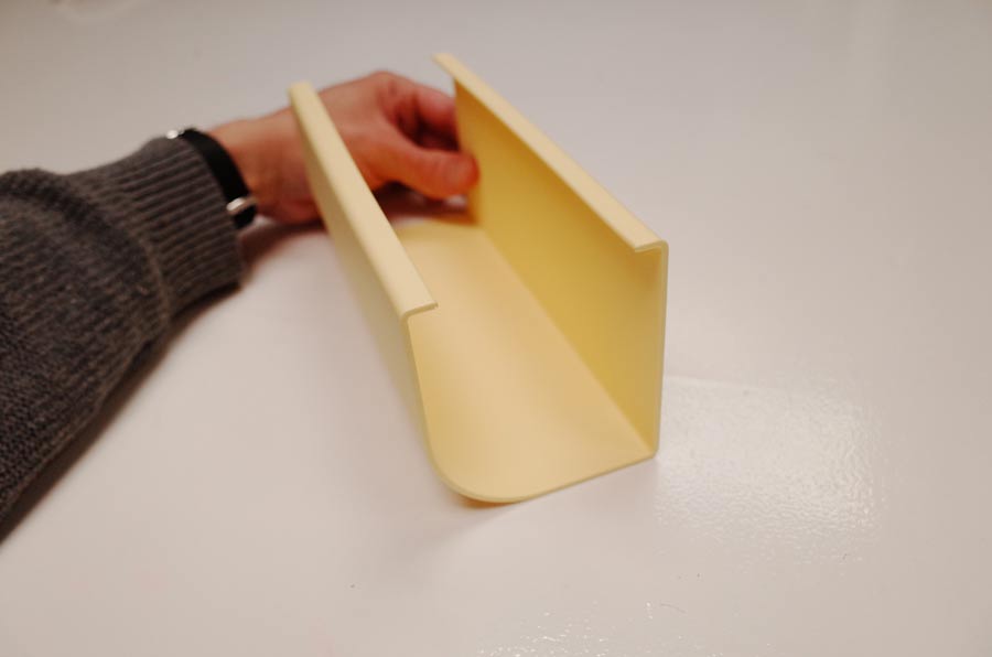
I then sliced the veil using two offset planes, at distances I thought would be appropriate for a future enclosure design. These planes were at 90 degrees from the XY origin plane of the workspace. This would allow the front and back of the veil to be parallel to the face of the future enclosure design.
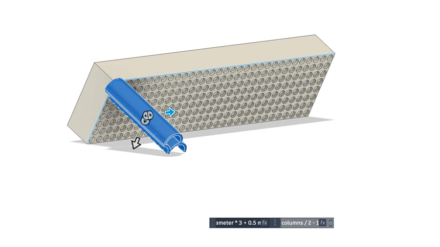
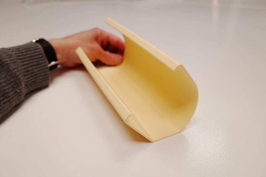
I then sketched and extruded a box that would cut off the excess pattern geometry.
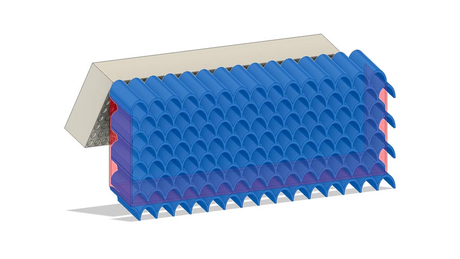
I used the combine tool to first cut (by selecting Keep tools, to keep the edge geometry) and then join the outer edge to the rest of the veil.
The complex geometry of the scalloped openings being extruded at an angle would make this extremely difficult to machine or cast. Also, the ribbed texture from thick layer lines was a design choice which would only be able to be faithfully reproduced with FFF printing.
I wanted to achieve a transparent ribbed textured pattern throughout the veil, for a pleasing light distortion and texture.
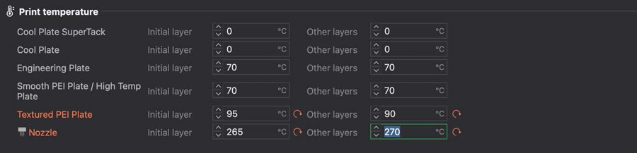
I replaced the 0.4mm nozzle on the BambuLabs A1 with a 0.8mm nozzle.
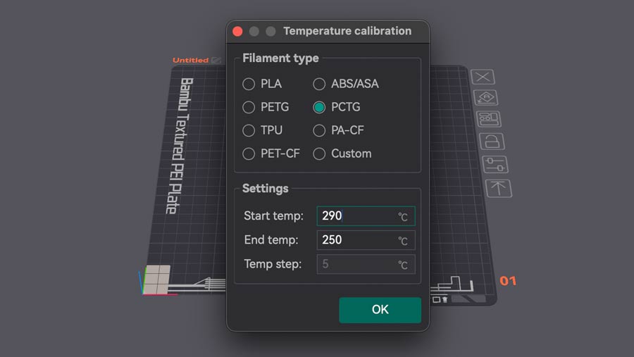
I also purchased a roll of transparent PCTG, since our local shop was out of transparent PETG. I used Athenax PCTG by FormFutura. I dried the new roll of PCTG for 16 hours in a filament dryer.
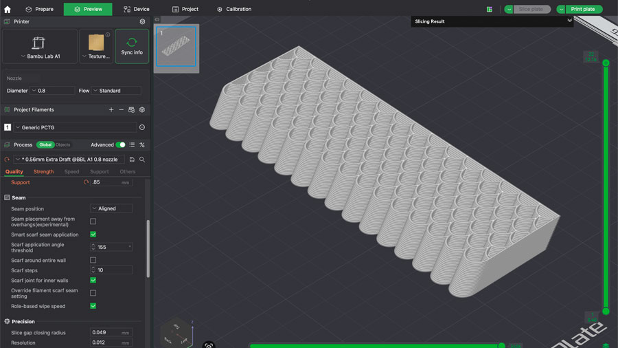
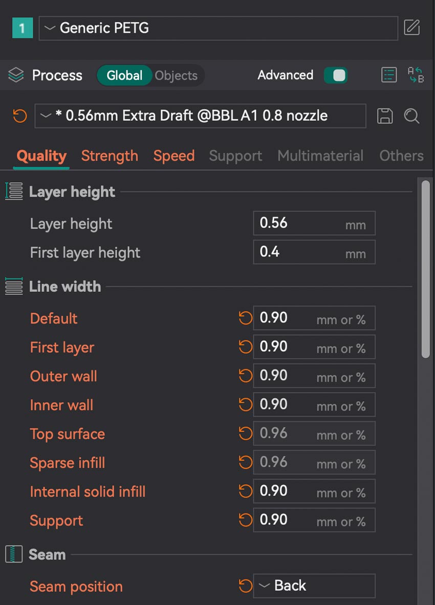
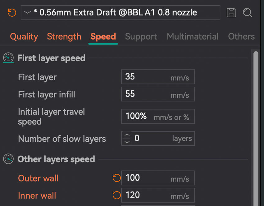
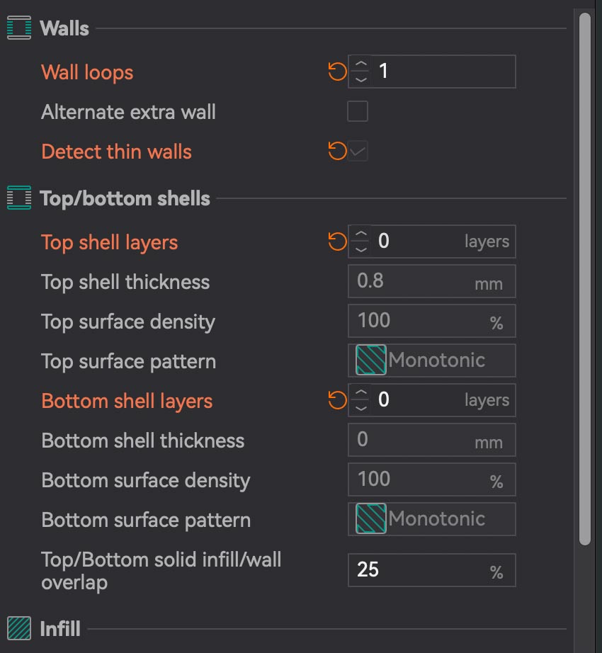
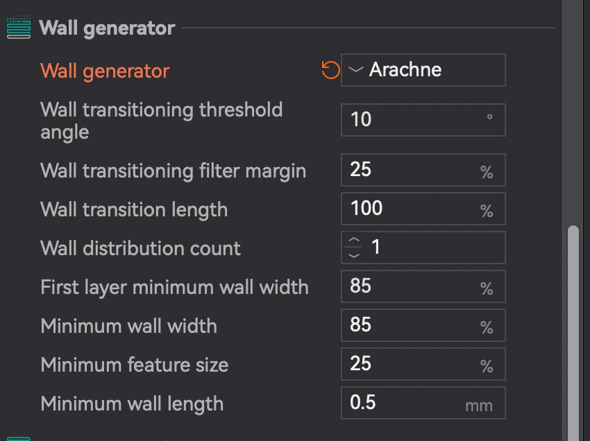
I exported the veil to the BambuStudio slicer and set the following settings:
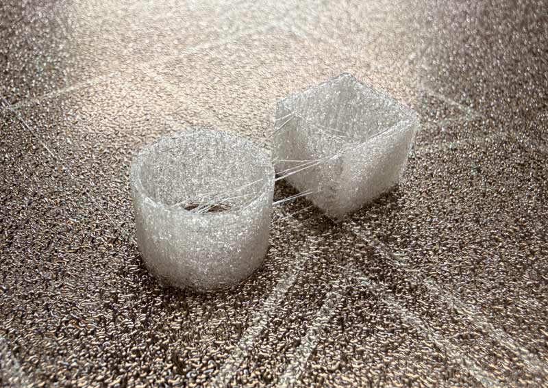
I could tell right away that this wasn't going to give me the desired effect.
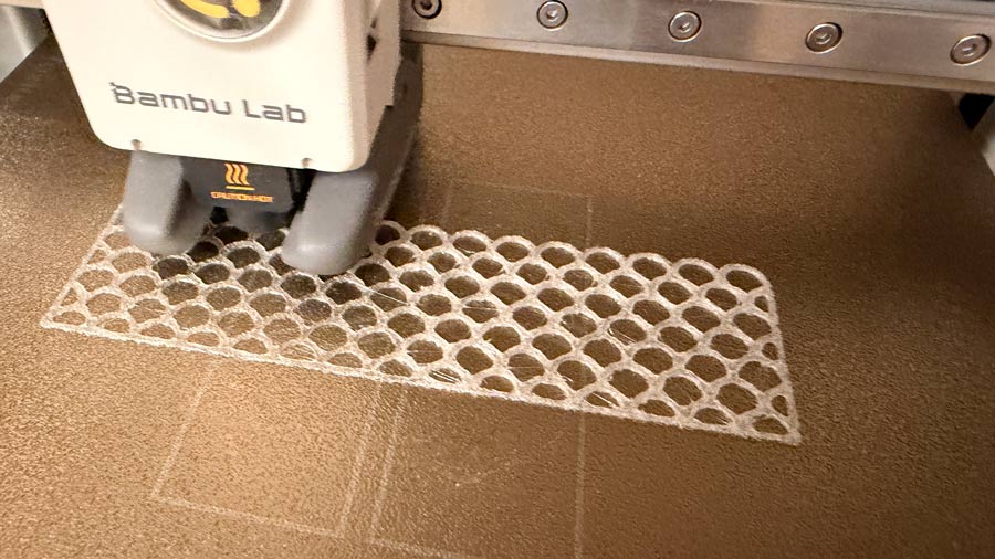
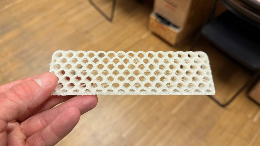
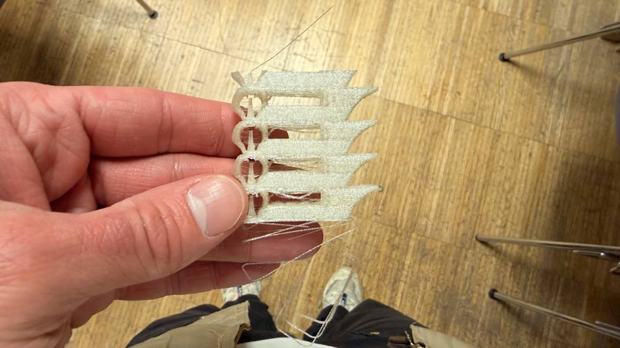
The result was very cloudy, with a rough finish, and lots of stringing.
I decided to print some tests until I achieved the desired result.
First, I wanted to create some temperature towers. I switched over to the Orca slicer because it allows you to create custom temperature towers.
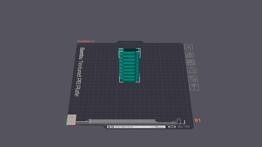
I printed the first temperature tower on the A1 with a 0.8mm nozzle
I printed the first temperature tower on the X1 Carbon with a 0.4mm nozzle
Neither of the temperature towers were giving good results. I decided I should concentrate on speed and flow calibration tests instead.
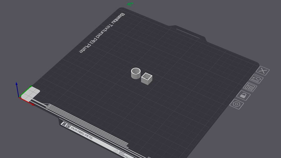
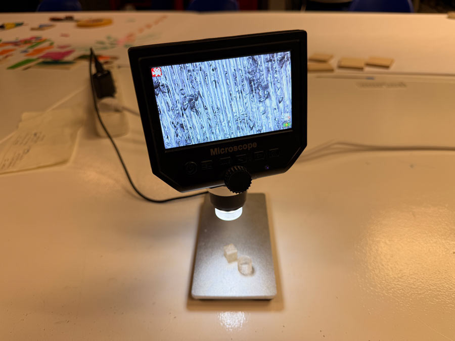
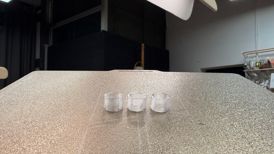
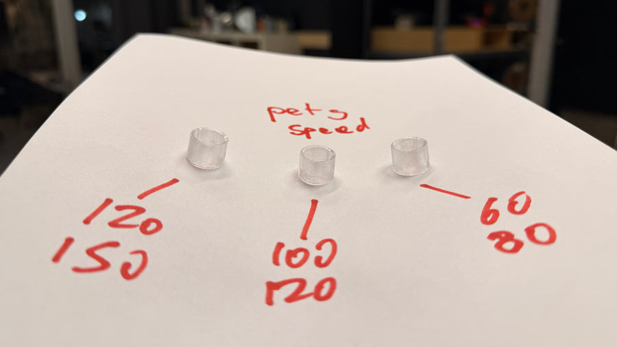
I decided to test two small test objects. One with a round edge and one with straight edges. I used much slower speeds for the speed tests than any of my previous tests.
Print settings used for first test:
Print settings used for second test:
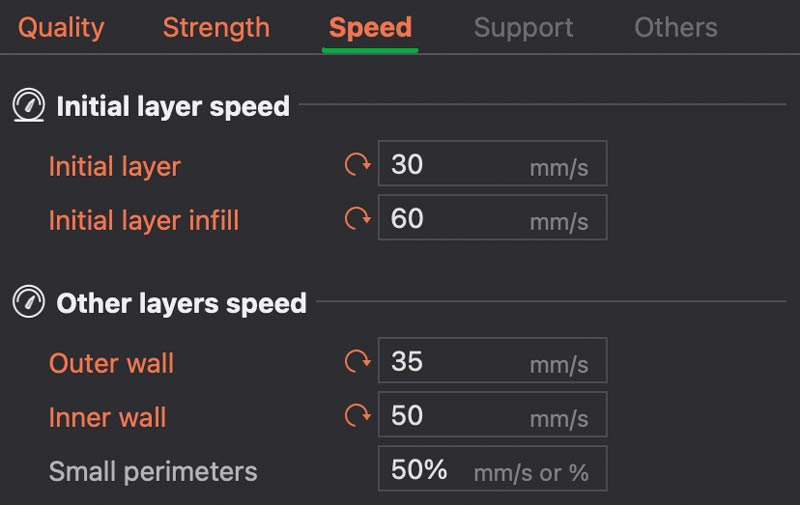
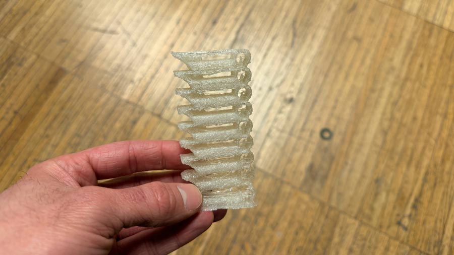
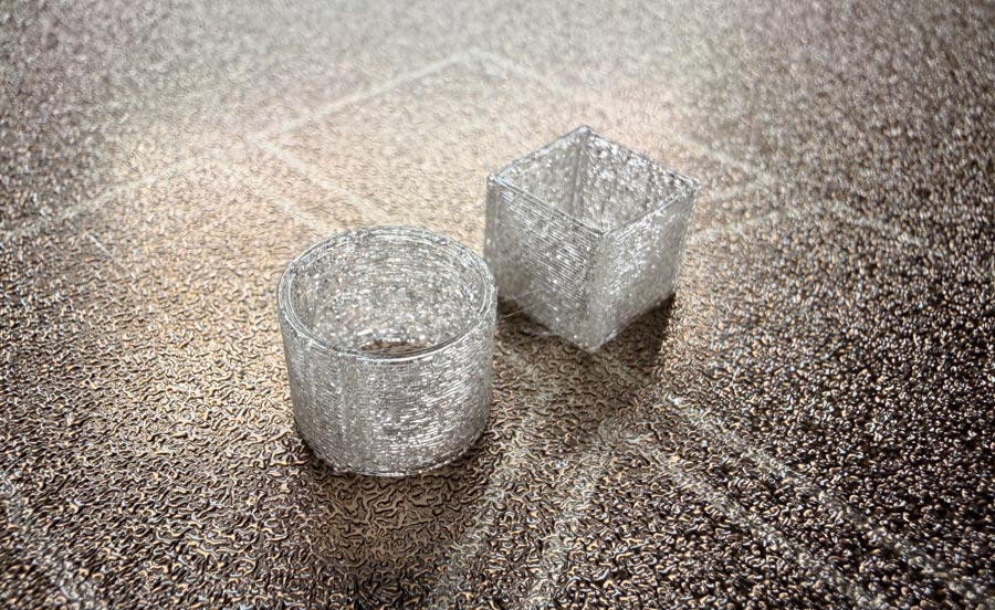
The first speed test (with slower speeds) gave better transparency results, less bubbles, and less stringing. Clearly slower speeds were the key here.
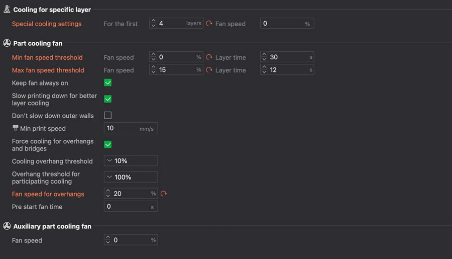
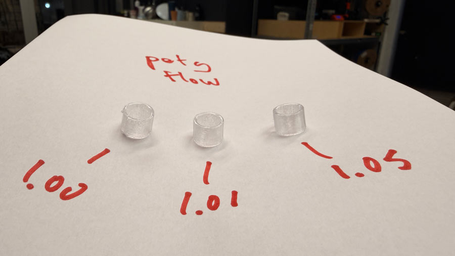
Next, I wanted to try some flow calibration tests to see if that could improve the transparency. Flow calibration is used to check whether a 3D printer is extruding too much or too little material, and adjusting the flow rate can help reduce gaps from under-extrusion or excess material from over-extrusion, both of which can affect the clarity of a transparent print. I thought this may explain some of the rough surfaces and messy layer lines I was getting in previous prints.
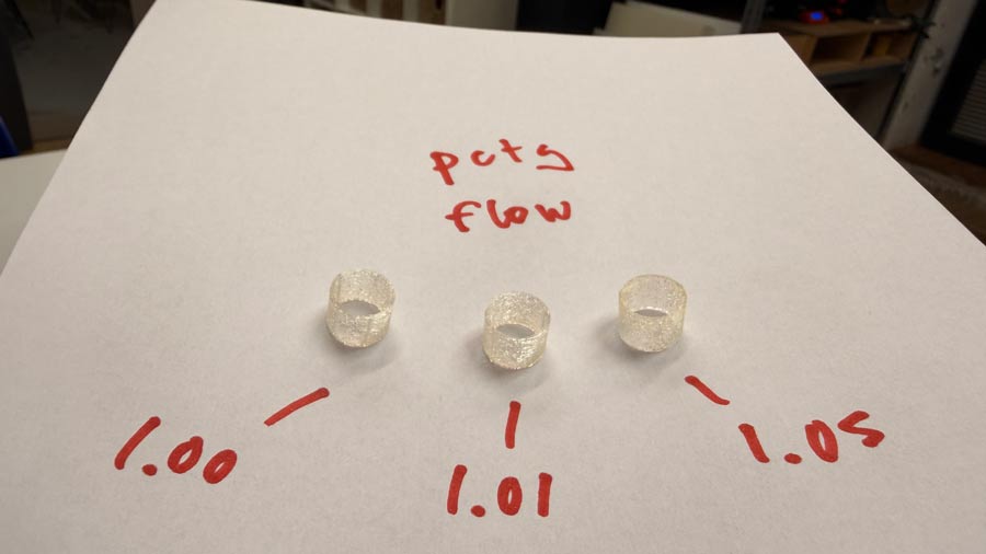
The differences were very minimal but it seemed like the higher flow yielded better results, which is what I had anticipated.
Suddenly, everything became clear.
Even with much faster speeds, the PETG was printing much clearer than the much slower PCTG.
Overall, slower speeds and higher flow appear to yield better results for transparency, though the differences were difficult to perceive in these tests.
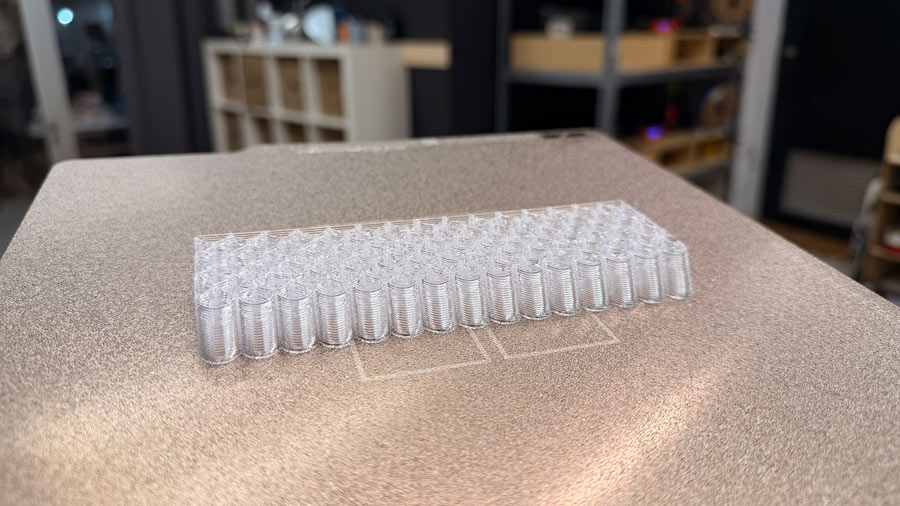
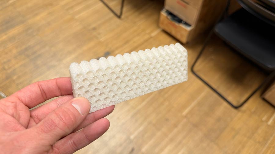
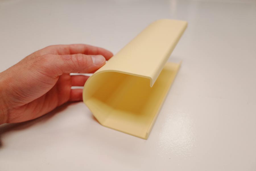
In the end, the PETG veil turned out to be quite nice. The transparency was sufficient for the application I was considering. However, I still wanted thicker and more pronounced layer lines, for more texture and light distortion. This could lead to further exploration in the future.
For a different test, I decided to deviate from the scalloped veil in favour of a rectilinear veil. I just wanted to explore a different geometry.
Again, this one was mapped to the position and dimensions of the MAX7219 display model.
Again, it was extruded and split using an offset plane, but this time the plane followed the curved body of the enclosure.
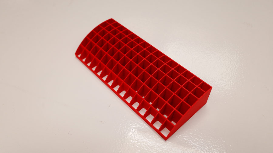
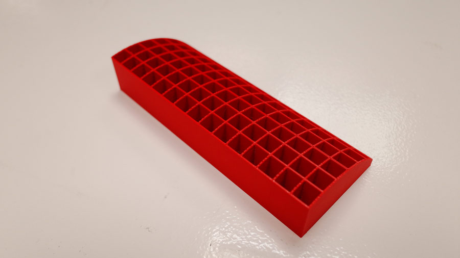
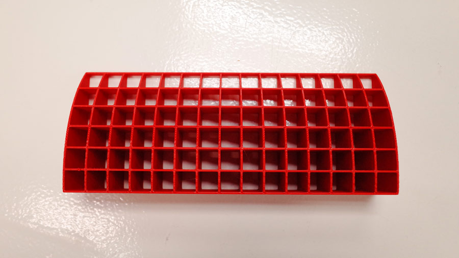
The result was very clean and quite striking in red.
I then decided to experiment with a few alarm clock enclosure shapes. The idea was to explore forms that could be tilted to provide an on-axis view of the display through the veil, then return to an off-axis position when resting.
We were also introduced to the basics of 3D printing with natural materials such as clay. This was interesting to me since I was considering it as a possible enclosure material for my final project. The use of Grasshopper with Rhino was less interesting to me. I'd be intersted in seeing if I could use Fusion Manufacturing toolpaths for this in the future.
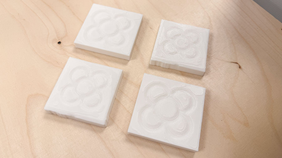
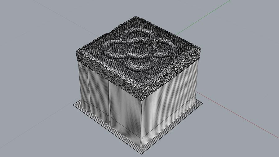
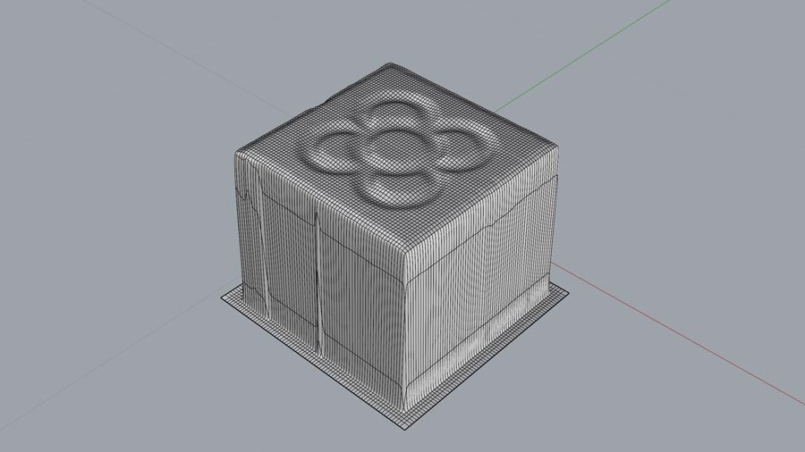
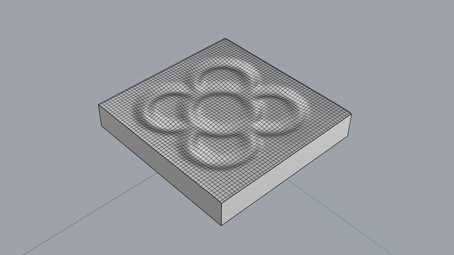
I love a good tile. And since I had already played around the Flor de Barcelona tile motif in one of my week 03 assingments, I decided to grab a real tile we had laying around at the lab to make a detailed 3D scan.
To do this, I used Polycam on my phone using "Guided object mode". This specific scan came out to 104 frames and worked well. I found Polycam to be very reliable.
I imported the STL into Rhino and decided to use the drape command to get a smooth closed surface that would take on the shape of the mesh (which can be messy sometimes when 3D scanning).
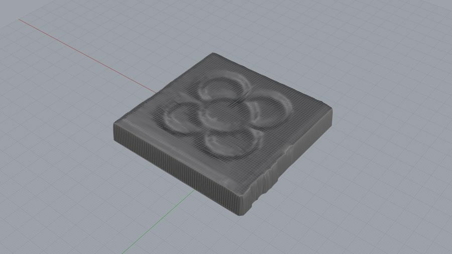
I decided to make two versions: one that preserved the tile's original rough edges by wire-cutting only the bottom surface, and another with clean edges achieved by wire-cutting the sides as well.
I also used different amounts of smoothing in the drape settings for the two versions.
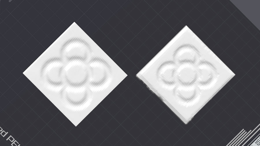
You can see the difference in smoothing below in the slicer.
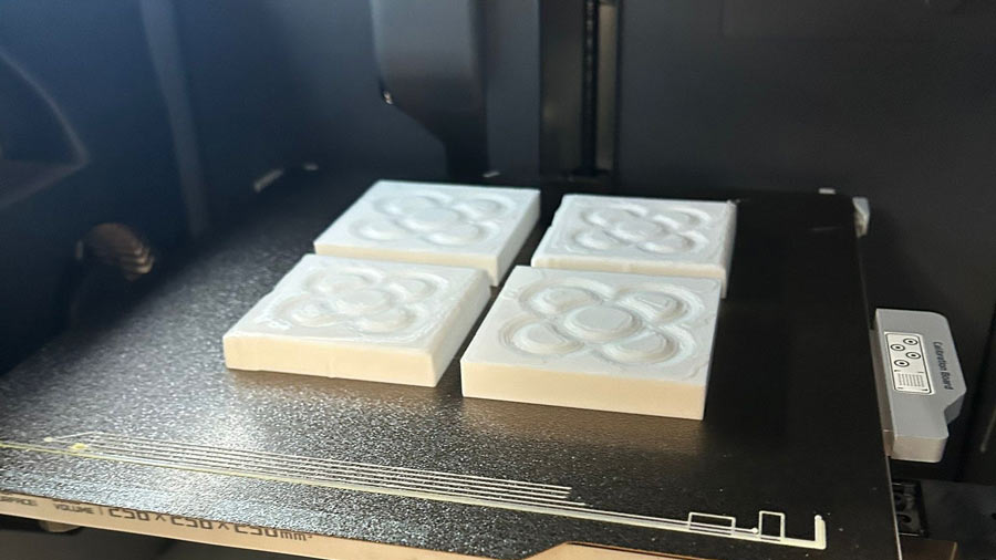
The results, printed out of white PLA.