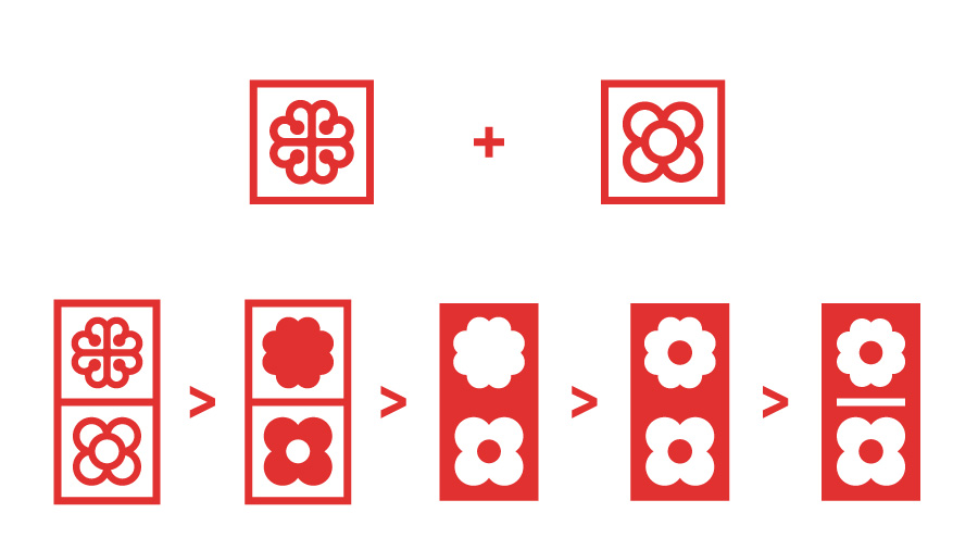
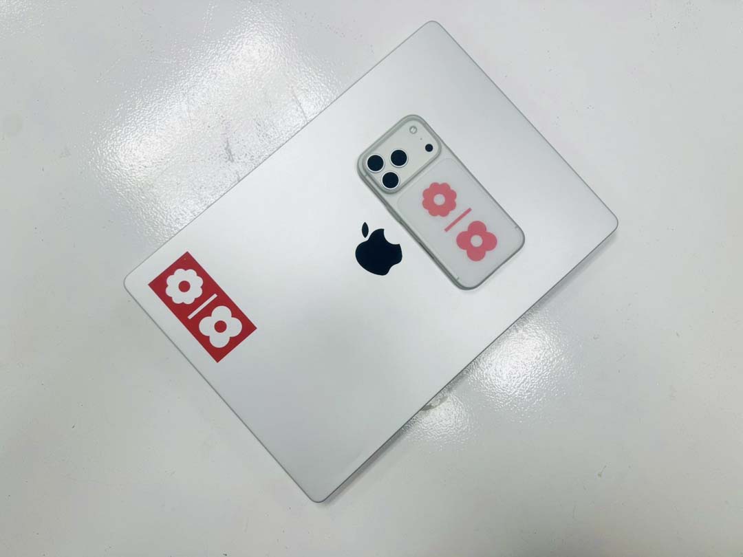
Flor de Barcelona panot + Montreal official logo, redesigned to create two cohesive tiles.

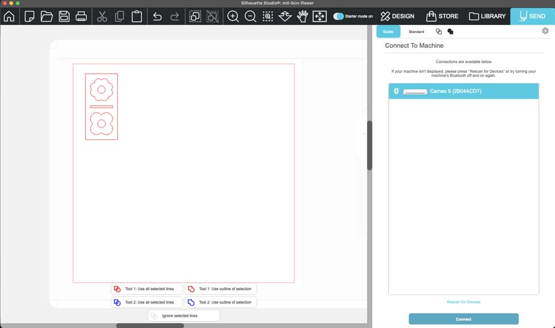
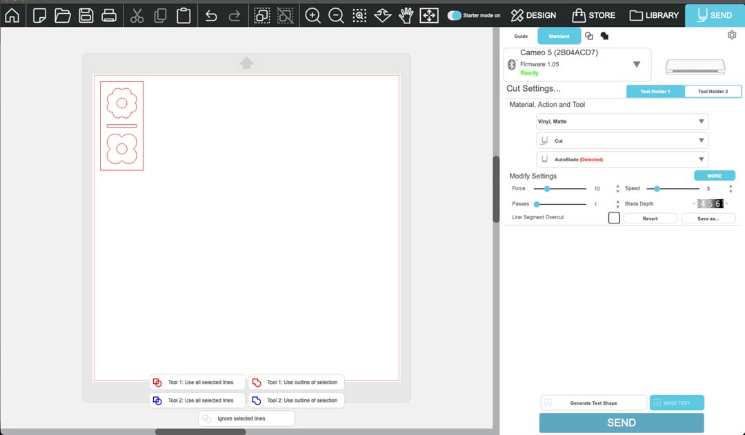
With the design ready, I exported it as a dxf file from Illustrator. I then opened the dxf file in Silhouette Studio and placed it in the upper left corner, near where the cutting tool would be.
I connected to the Silhouette Cameo 5 over bluetooth, which is done by pressing the bluetooth logo on the machine and waiting for it to turn blue. The machine then appears in the software.
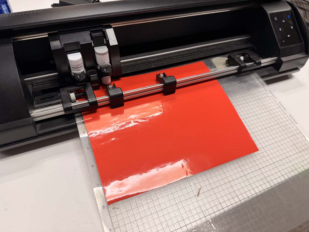
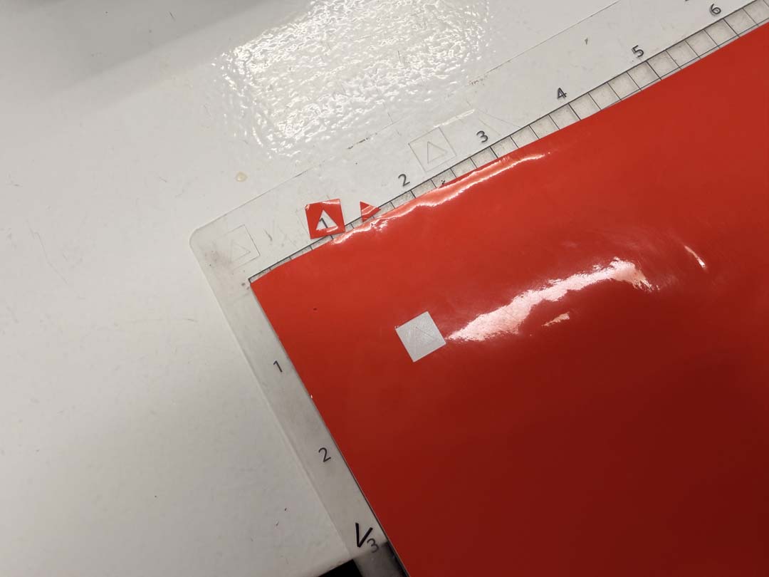
For loading the material, I stuck red vinyl onto the cutting mat, with the backing still attached.
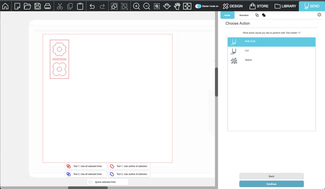
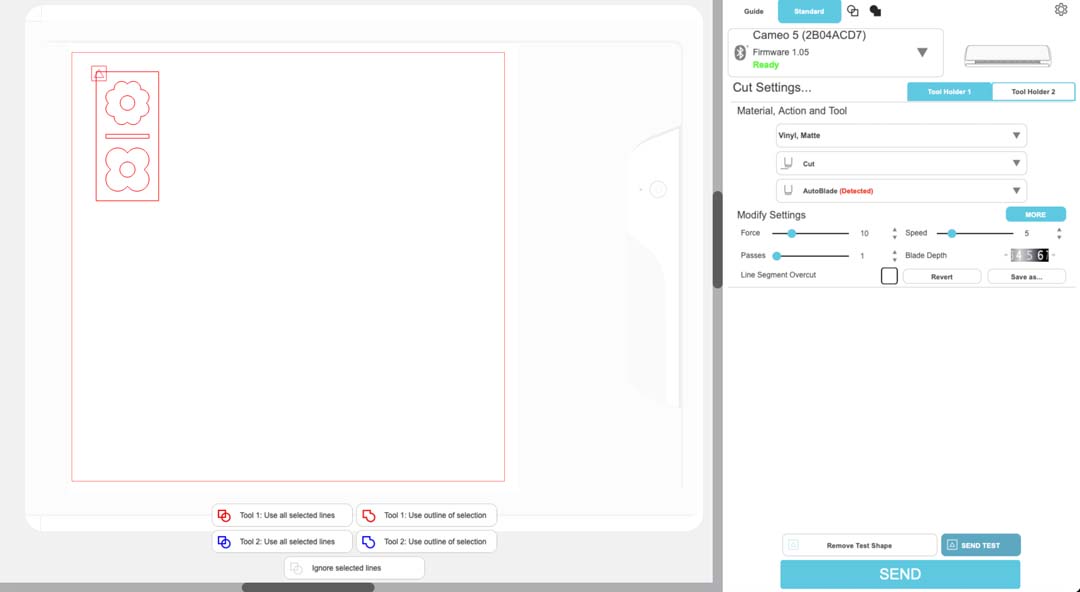
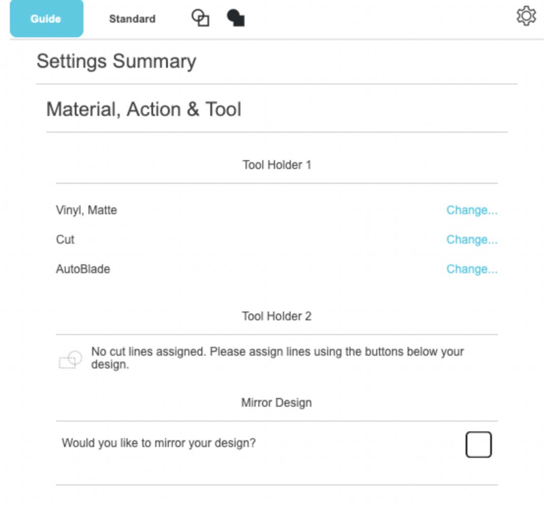
I set the material to vinyl, matte, with the AutoCut action and the AutoBlade tool.
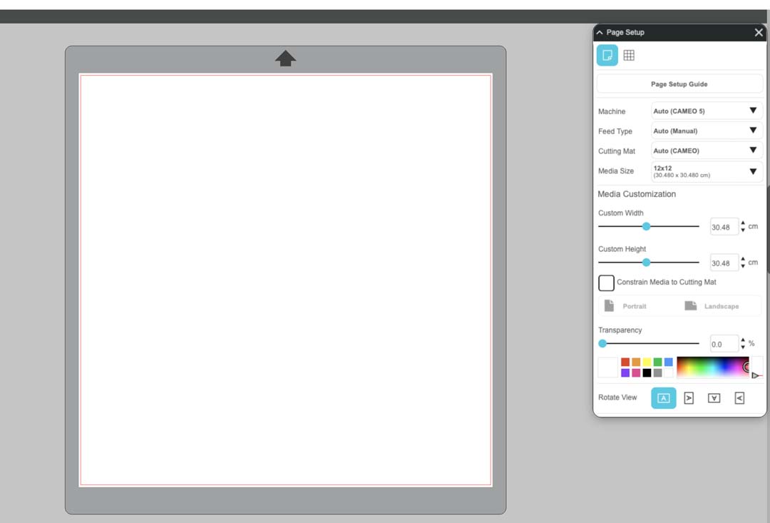
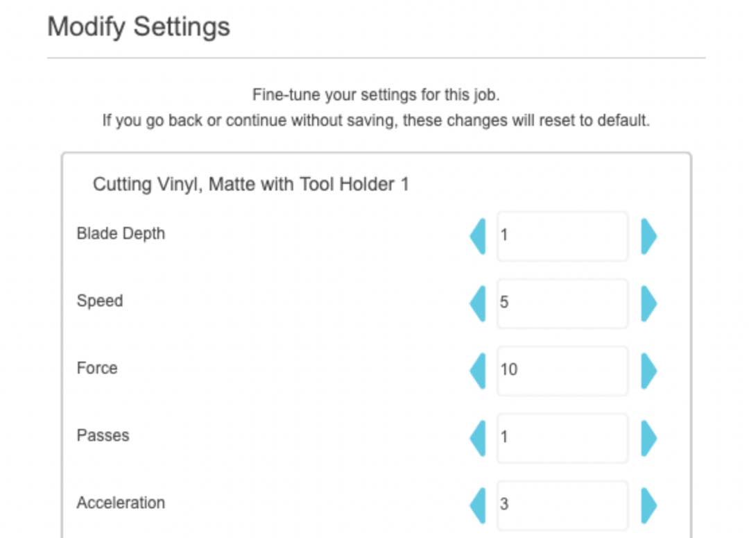
My first attempt had the wrong mat and media settings. The below settings led to the machine cutting the test cut in the upper right corner, so the canvas was rotated 90 degrees clockwise from the reference on the screen.
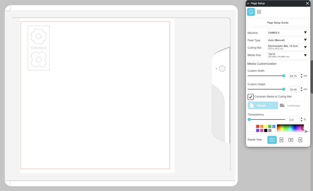
The following settings translated to the correct orientation on the machine. You can see that the cutting mat graphic in Silhoutette Studio looks different.
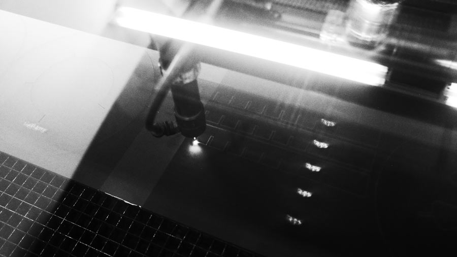
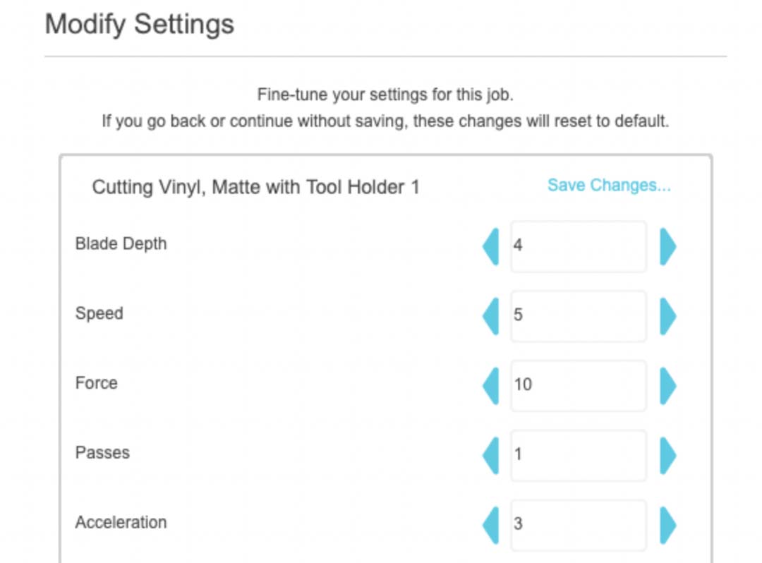
Before committing to the full cut, I sent a few test cuts to dial in the blade depth. The fact that the test was overlapping the design didn't matter, because you can adjust the XY origin by moving the cutting mat with the controls on the machine.
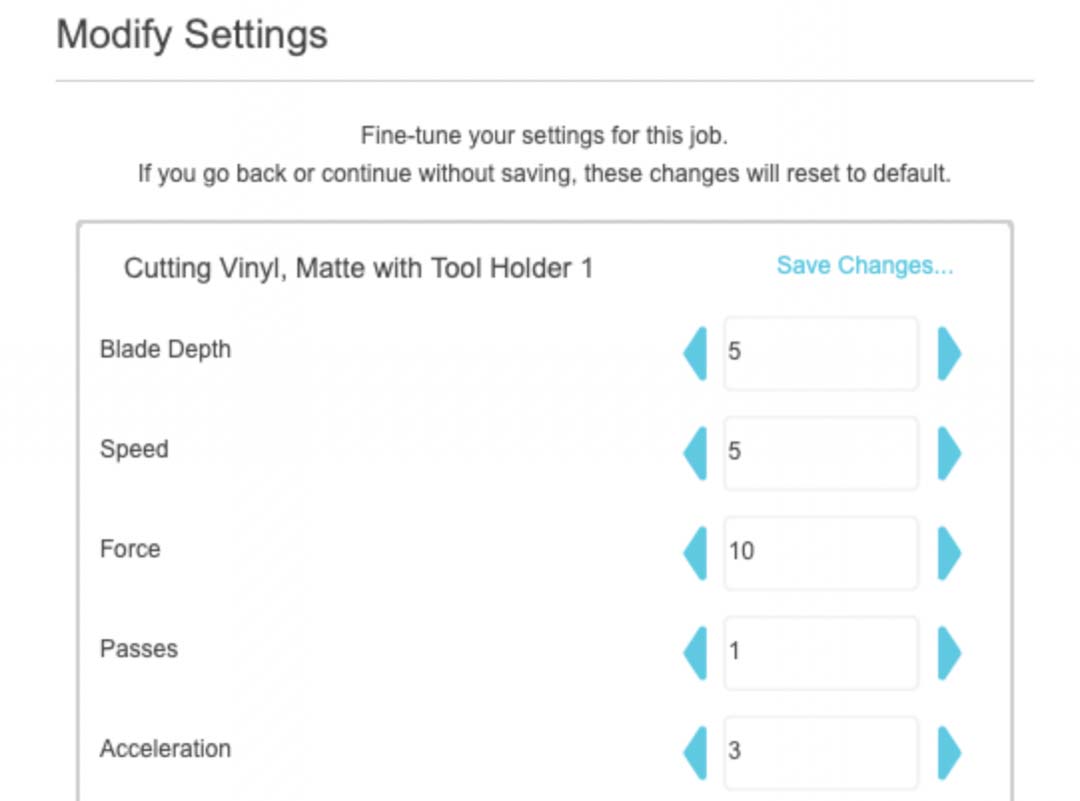
Blade depth 5 cut cleanly through the vinyl without cutting into the mat.
The cut was really quite fast.
Once cut, used transfer tape to lift the vinyl off the mat. I was able to get both the positive and negative of the design transfered onto seperate pieces.
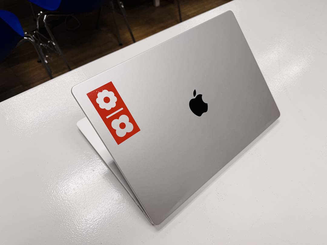
The final stickers ended up on both my laptop and my phone case.
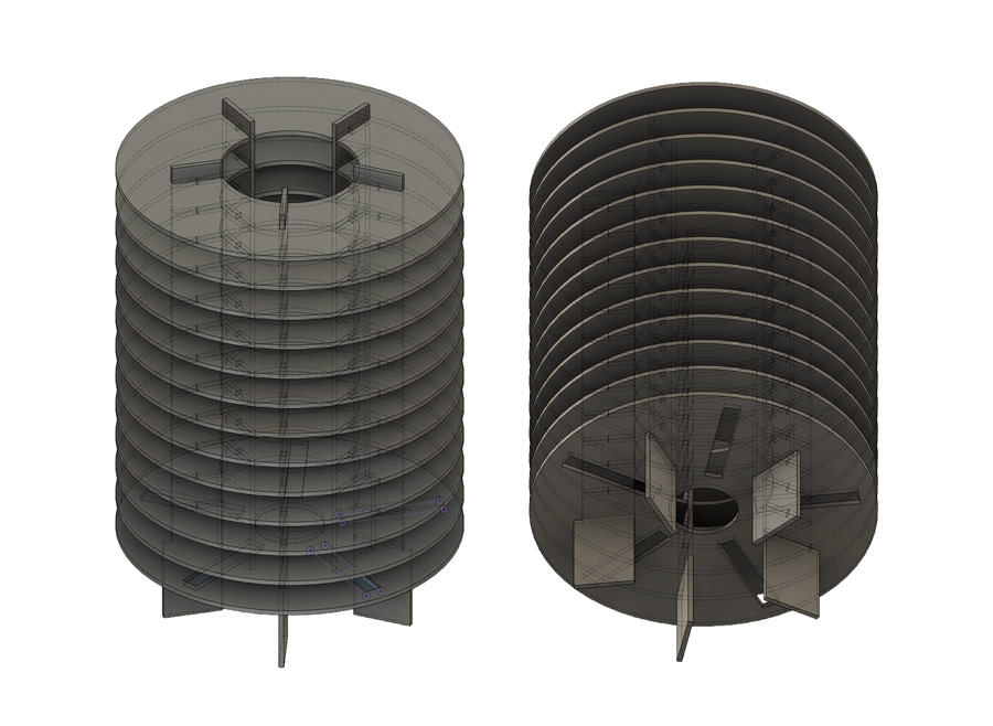
I decided to create a parametric design in Autodesk Fusion that allows you to choose the height and width of your lamp. Each slice is adjusted accordingly and ready to laser cut.
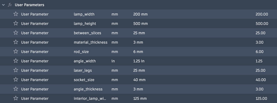
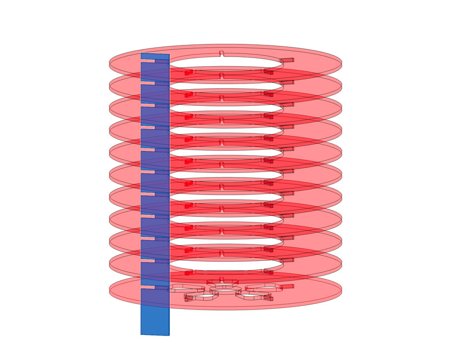
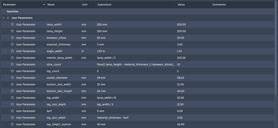
I first defined a set of parameters that would allow me to create the first model of the lamp.
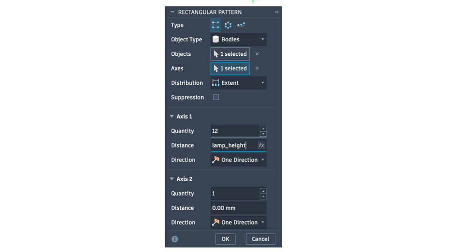
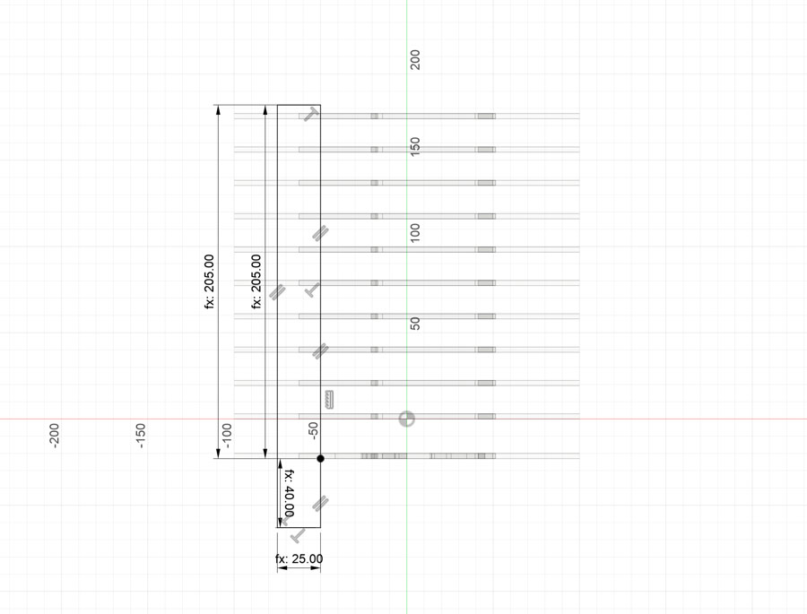
For this first version, I was setting the rectangular pattern of vertical slices by setting them to the extent defined by the lamp height parameter.
The first approach wasn't getting me the result I wanted. I needed the quantity to also be updated parametrically and for the slices to always be evenly spaced out vertically.
I tried to see if ChatGPT could help me find a solution for a good expression to use. It introduced me to the "floor" function in Fusion.
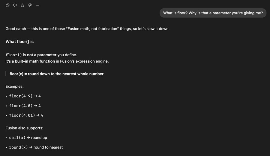
Floor allowed my expression to always calculate a whole number of slices at even distances, with only slight variations in the spacing between height changes.
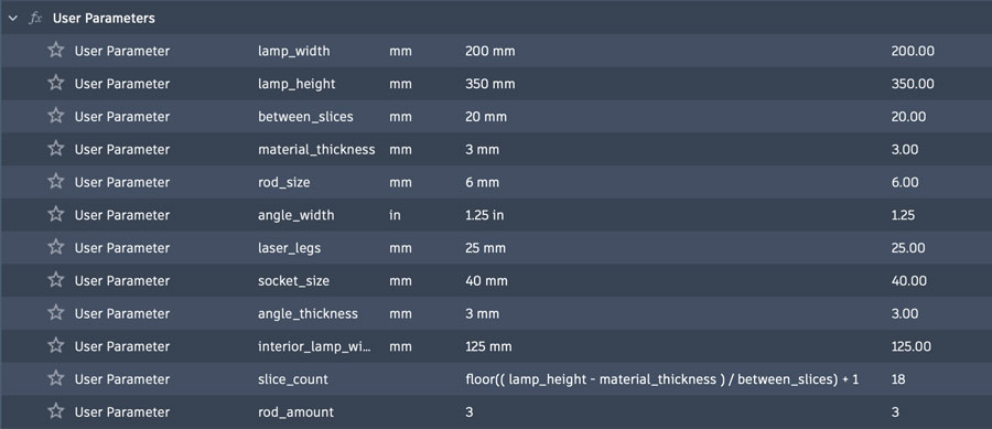
The expression: floor((lamp_height - material_thickness) / between_slices) + 1
The explanation: "Stack slices upward at roughly between_slices apart until I run out of height, and give me a whole number of them."
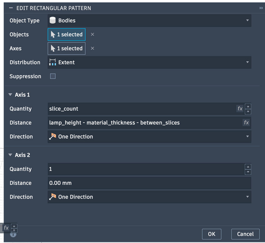
I then used this new slice_count parameter as the quantity for the rectangular pattern, and used lamp_height - material_thickness - between_slices for the distance.
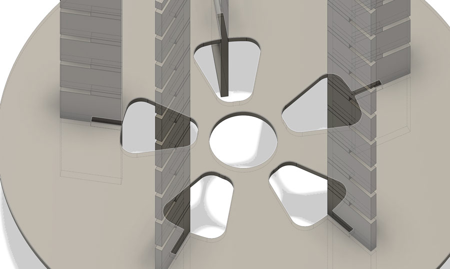
The first version of my lamp simply used holes in a circular array to allow threadded rods with nuts to be used as the legs.
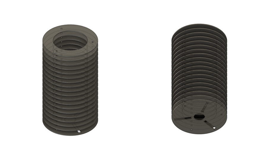
I did encounter an issue with this version, which caused the number of bottom slots and number of holes for the legs to clash when changing the amounts.
In order to fulfill the weekly assigment, the "parametric construction kit" needed to have joints between lasercut parts.
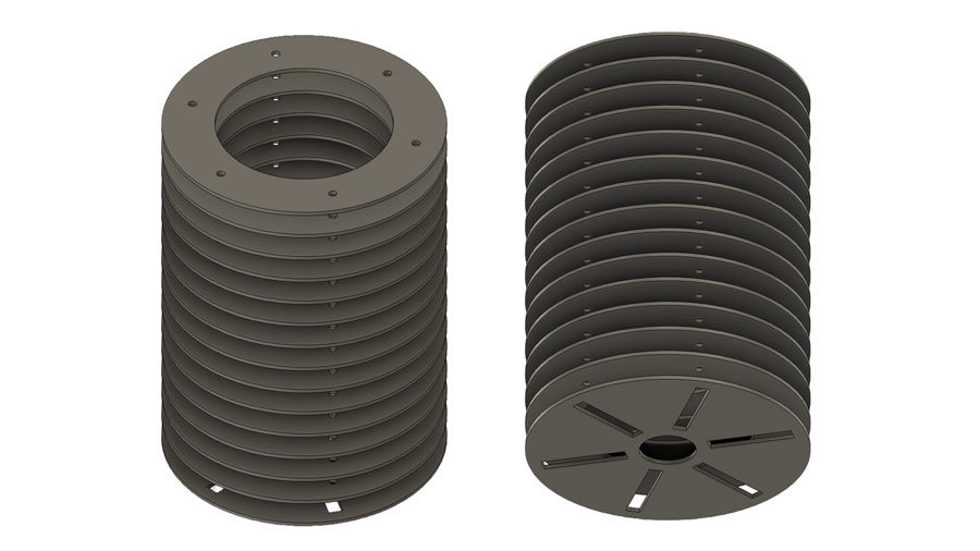
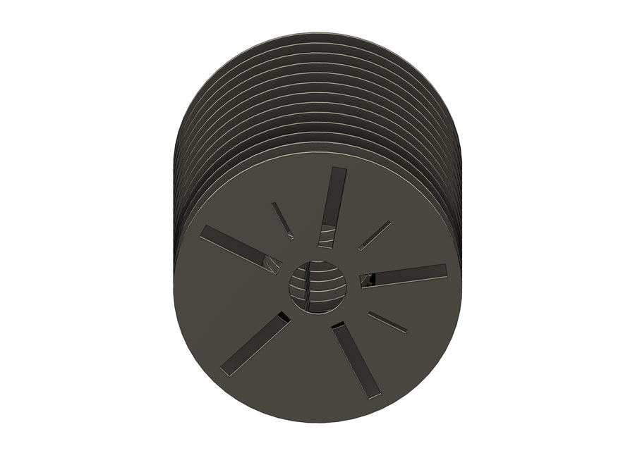
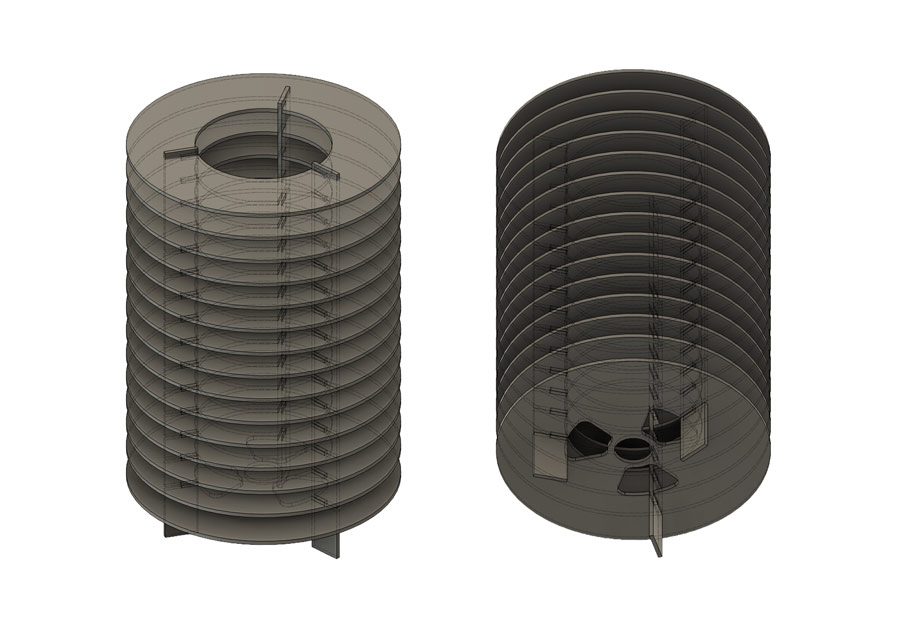
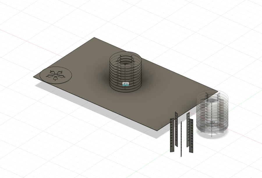
So I designed a second version with laser cut legs instead of threaded rods.
I had another parametric issue with the number of leg slots.
In order to fix this, I used a new approach to the sketch design. Using the dimension tool, I set a defined angle between the start of the leg slot hole and the centre of it.
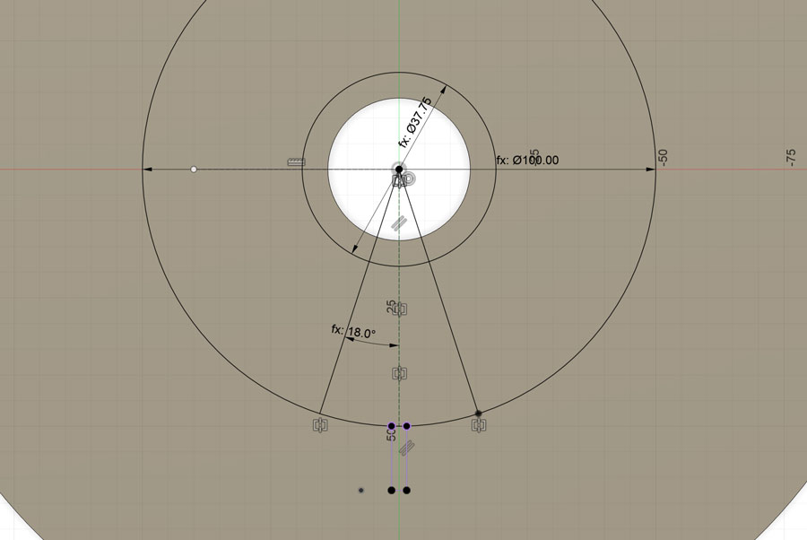
I set the parameters of the legs dimensions in the sketch so that they could update parametrically with the lamp dimensions.
I also added fillets to the leg holes to refine the design a bit.
I used Fusion's Combine tool in order to combine the two main componets: the slices and the legs. This made sure the joints would be automatically created by subracting the slice positions from the legs.
This approach worked well.
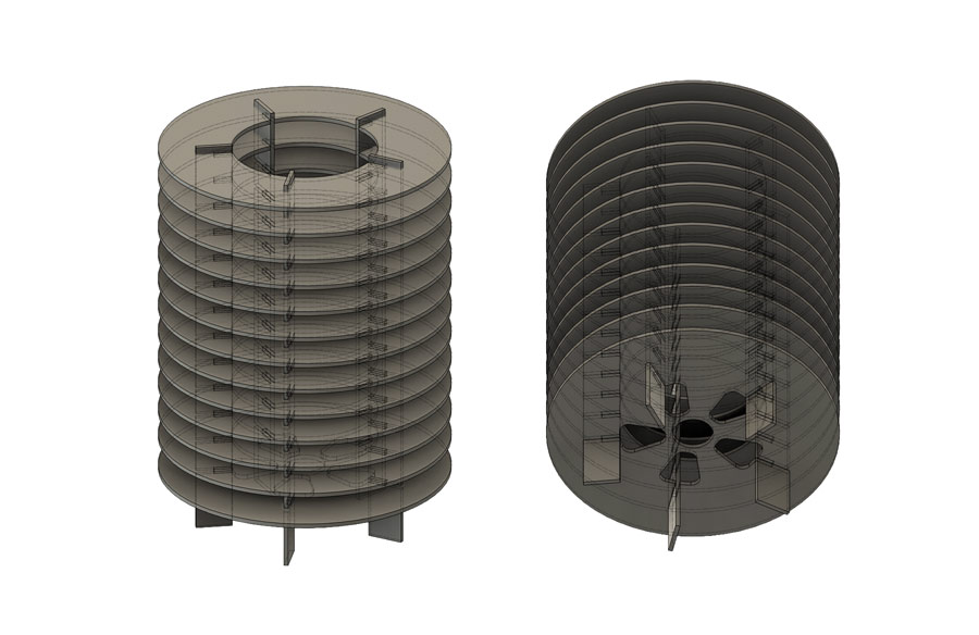
With this full set of parameters in place, I could resize the entire lamp just by changing the height and width values, and the model would update on its own.
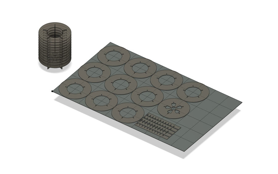
I order to create the 2D vector file for laser-cutting all then pieces, I had to lay them out onto a sheet using my parametric model.
At first I tried using the Arrange or Join tools in Fusion, but I was having trouble with whole assemblies of bodies from each component moving together. This wasn't working.
I found a solution by using the Align tool instead, and moving them to specific points on the material surface.
Main points:
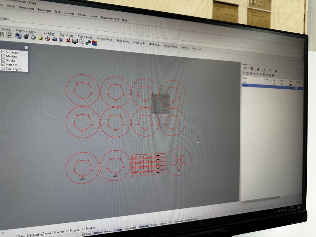
Before sending the file to the laser, I set up the cut and engrave lines on separate layers with different colours in Rhino, since the laser software reads line colour to decide which operation to run on each line.
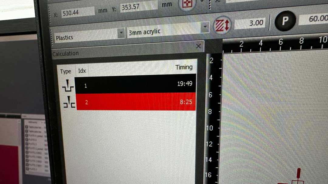
The laser-cutter software calculated about 19:49 for the engraving pass and 8:25 for the cutting pass on 3mm acrylic.
PPI vs Hz:
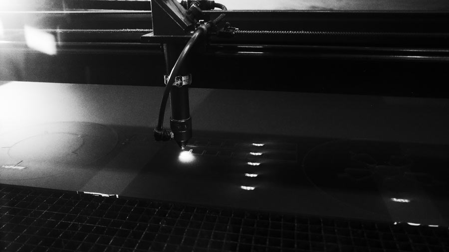
First, the text was engraved for labeling the peieces. However, this was a learning moment, because our Rayjet 500 does raster engraving by sweeping across the whole canvas for each line. This is extremely inefficient, and could have been more efficient if I had laid out the pieces differently to reduce the width of the sweeps on the engraving portion.
Then the slices and legs were cut out.
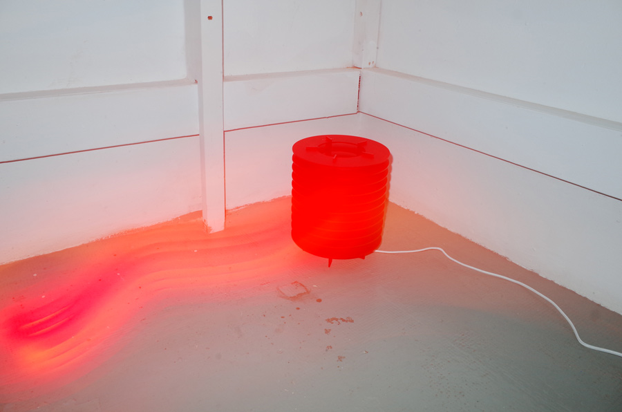
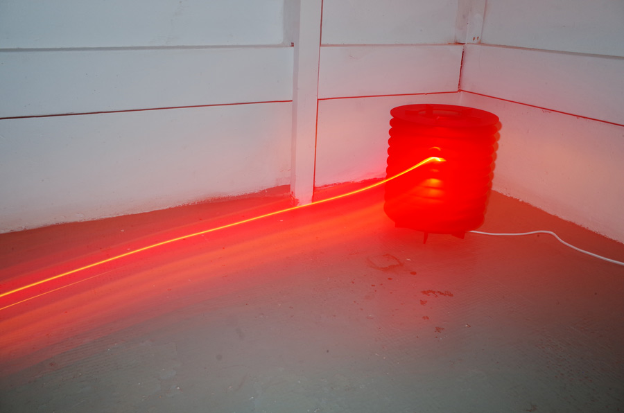
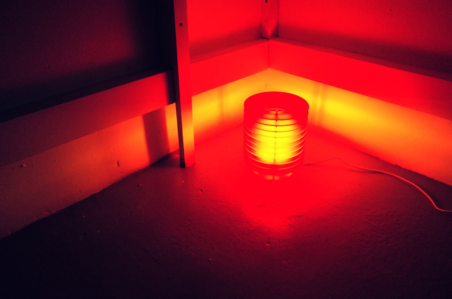
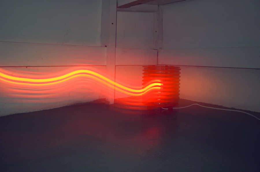
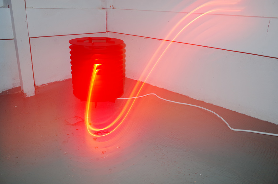
Despite the face I'm making in the photo below, the assembly went well and all the pieces fit together neatly.
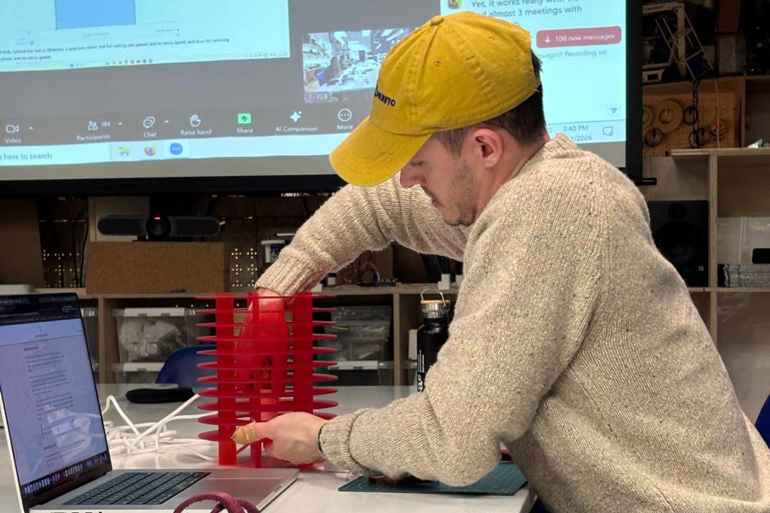
I had set the material thickness to exactly 3.00 mm in my parameters, and the kerf we calculated in our group assigment for the week allowed for a good tolerance for press-fitting. I was able to screw/clamp the base slice with a STRÅLA cord set for the lighting fixture. I also wrapped the bulb I had bought in Kapton tape in order to give it a much warmer glow.