The Intermission Object is a handheld ritual device for finite, screenless breaks. The user picks it up and turns an outer dial to begin the intermission. Warm LED light slowly appears through the ribbed clear body. A geared DC motor drives an internal rotor with steel pins, magnetically coupled to the outer dial. If the user lets go, the dial moves with the mechanism. If they hold it still, the coupling slips and soft pulses are felt through the fingers. Light, haptics, and subtle sound respond to the state of interaction throughout.
The experience is finite, but its duration varies slightly each time. The user cannot know exactly how long it will last, and their interaction may influence the pace in ways that are not fully predictable. At the end, the motion stops, the light changes, and a haptic or sound cue signals closure.
2. Who's done what beforehand?
Calm technology / ambient devices: Mark Weiser and John Seely Brown's foundational work on calm computing; ambient devices in general as precedents for conveying information through non-screen, peripheral means
Fidget toys: Products like the Fidget Cube and spinner toys explore tactile engagement as a focus or anxiety tool, but without a finite experience or intentional ending
Time tools for ADHD: Pomodoro timers and similar tools address time blindness but rely on numbers or screens
Ritual and break design: Research into the psychology of micro-breaks and restorative experiences in workplace contexts
3. What sources will you use?
Seeed Studio XIAO ESP32S3 documentation
Adafruit learning system
Arduino / ESP-IDF community documentation
Braun design archive
Firsthand experience with ADHD and time blindness as a primary reference for the project's motivation and design intent
Research on restorative micro-breaks: Ariga and Lleras (2011), "Brief and rare mental 'breaks' keep you focused," Cognition
Richard Klein, Cigarettes Are Sublime (1993), on the ritual, pleasure, and structure of smoking as a cultural and temporal act
4. What will you design?
Jesmonite AC84 cast base: the bottom section of the object, forming the speaker chamber; cast in a mould milled from wax
Clear resin middle section: cylindrical light-diffusing body with a ribbed texture to distort the warm LED glow; printed in clear resin
Clear resin top dial: the rotating outer interaction surface with embedded magnets; printed in clear resin
PLA/PETG top section: the upper structural part of the object housing the dial mechanism and motor; FFF printed
Inner rotor with steel pins: the motor-driven magnetic coupling component
Internal structural and mounting components: battery mount and component holders; FFF printed
Custom PCB: integrating the XIAO ESP32S3, MOSFETs for motor and LED control, hall effect sensor input, and connections for haptics and audio
5. What materials and components will be used?
Materials:
Jesmonite AC84 (base casting)
Clear resin (middle section and top dial, SLA printed)
PLA or PETG (top section and internal structural parts, FFF printed)
Phenolic paper PCB substrate
Neodymium magnets (embedded in outer dial)
Steel pins (inner rotor)
Bicycle headset bearing
Components:
Seeed XIAO ESP32S3 Sense
5000 mAh USB-C battery bank (de-cased)
Hall effect sensor
MOSFETs (motor speed control via PWM; LED dimming via PWM)
N20-style geared DC motor, 15 RPM
Flexible COB LED filaments (2220K, 3V, 100mA each, wired in parallel)
LRA haptic actuator
Gravity TM6605 haptic motor driver module (DFRobot)
Adafruit MAX98357A I2S amplifier
3W 8Ω speaker
6. Where will they come from?
Fab Lab Barcelona inventory (XIAO ESP32S3, hall effect sensor, MOSFETs, PCB materials)
Battery bank: retail (repurposed from consumer product)
7. How much will they cost?
Component
Cost
Seeed XIAO ESP32S3
€7
N20 geared DC motor (15 RPM)
€6
Hall effect sensor
€0
MOSFETs
€0
COB LED filaments (10pcs)
€5
LRA haptic actuator
€2
Gravity TM6605 haptic driver
€9
Adafruit MAX98357A
€16
3W 8Ω speaker
€4
5000 mAh battery bank
€15
Bicycle headset bearing
€7
Neodymium magnets
€14
Jesmonite AC84
€19
Clear resin (SLA)
TBD
PLA/PETG filament
TBD
PCB substrate and components
€0
Total
€104 + TBD
8. What parts and systems will be made?
Made:
Jesmonite AC84 cast base (cast in a wax-milled mould)
Clear resin middle section with ribbed texture (SLA printed)
Clear resin top dial with embedded magnets (SLA printed)
PLA/PETG top section housing dial mechanism and motor (FFF printed)
Inner rotor with steel pins (FFF printed or machined)
Battery mount and internal structural parts (FFF printed)
Custom PCB (milled and soldered in-lab)
Firmware (Arduino/ESP-IDF on XIAO ESP32S3)
Bought:
N20-style geared DC motor (15 RPM)
Bicycle headset bearing
Battery bank
Neodymium magnets
LRA haptic actuator
Gravity TM6605 haptic motor driver (DFRobot)
MAX98357A I2S amplifier (Adafruit)
3W 8Ω speaker
Hall effect sensor
9. What processes will be used?
Moulding and casting: Jesmonite AC84 base, cast in a mould milled from wax
SLA / resin 3D printing: clear ribbed middle section and top dial
FFF 3D printing: PLA/PETG top section, inner rotor, and internal structural components
PCB milling and soldering: custom electronics board on phenolic paper substrate, in-lab
Embedded programming: firmware for motor speed control, LED dimming, haptics, audio, and hall effect sensor input on the XIAO ESP32S3
3D CAD (Fusion 360): all designed parts, including parametric enclosure and internal assembly
10. What questions need to be answered?
How will the intermission duration be determined internally, and how will user interaction influence it in a subtle, non-predictable way?
How sensitive does the hall effect sensor need to be to reliably detect the dial magnets through the resin, and what placement and threshold logic works best?
What firmware state machine governs the experience, and how are the start, active, and ending states defined and transitioned?
How will the power supply be kept clean and low-noise enough to drive the MAX98357A I2S amplifier without audible interference?
11. How will it be evaluated?
Functional: Does the magnetic coupling create the intended tactile experience? Does the hall effect sensor reliably detect dial interaction? Do light, haptics, and sound respond correctly?
Experience: Does holding the object feel intentional and calming? Does the ending state feel like genuine closure?
Fabrication quality: Is the Jesmonite cast clean? Is the clear resin optically effective as a light diffuser? Are the internal components well-integrated and secure?
Accessibility: Can the experience be meaningful without visual attention, through touch, haptics, and sound alone?
Fab Academy criteria: Does it demonstrate 2D and 3D design, additive and subtractive fabrication, moulding and casting, custom electronics design and production, embedded programming, and system integration?
12. Project plan and schedule
I started on the 10th of May, right after the first draft 3D model, with my final project presentation set for June 10th.
Week
Dates
Focus
Key deliverables
—
10 May
Draft 3D model
First draft Fusion model to work out shape, dimensions, and how the components would fit together
—
12 May
Mechanism test
Magnetic differential test dial printed and assembled
1
13 May – 19 May
Component testing
Individual system components tested on breadboard (battery, LED filaments, hall effect sensor, LRA haptic)
2
20 May – 26 May
Firmware and full system test
Firmware state machine written and tested; full breadboard system test; electronics design started
3
27 May – 2 Jun
Electronics design and first production
Main board and LED/hall effect board schematics and PCB layout finalised in KiCad; first boards milled and soldered; final CAD for enclosure begins
4
3 Jun – 9 Jun
Final CAD and final electronics
Final CAD for enclosure (electronics mount, top dial, bearing choice); final electronics boards milled and populated; SLA printing of resin parts
—
10 Jun
Final assembly and presentation
Final assembly, full system testing, documentation, and presentation — final project deadline
13. System architecture diagram
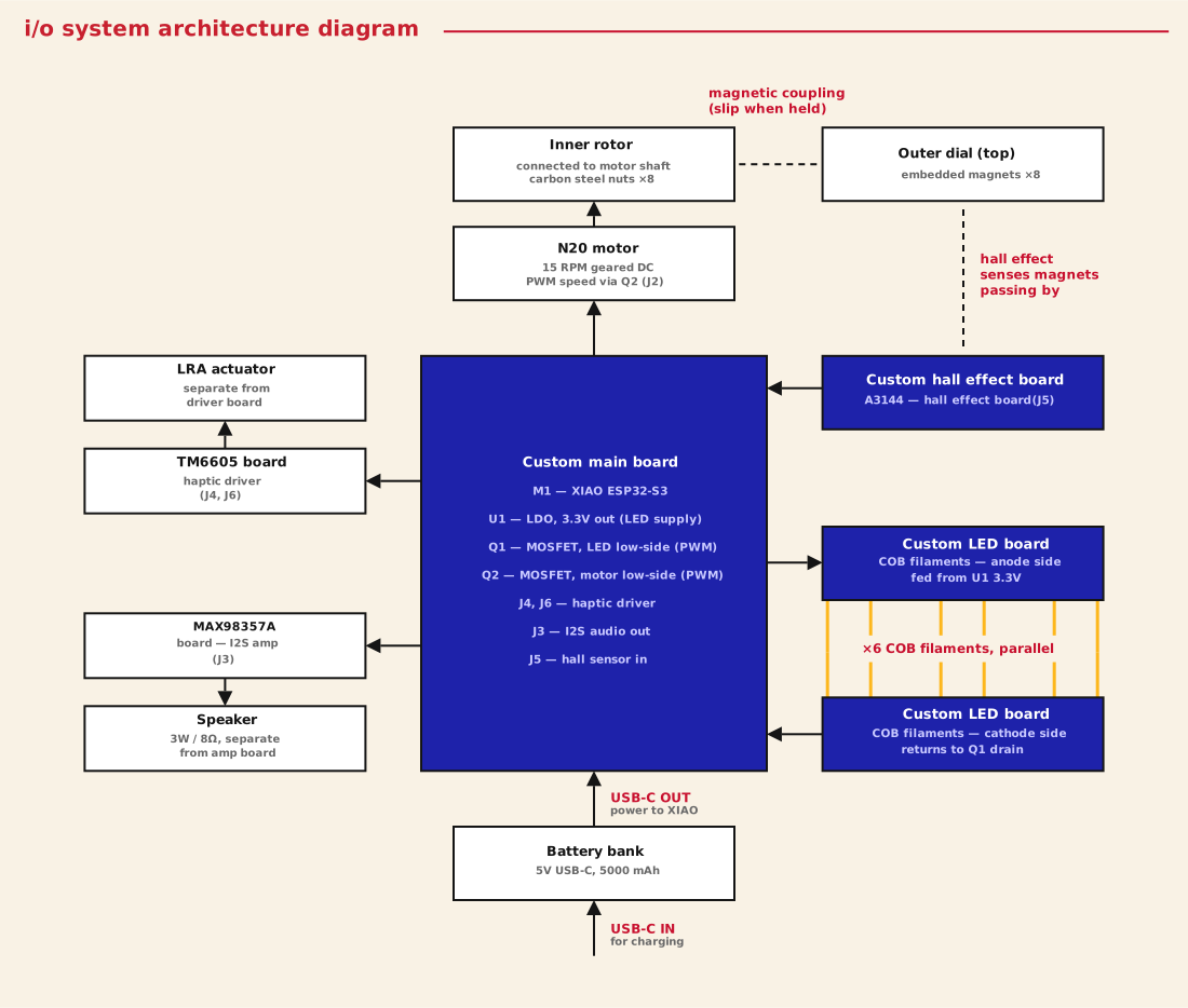
Diagram of the electrical system and the mechanical coupling. The battery bank has a separate USB-C charging input and USB-C power output to the XIAO. The main board has two separate MOSFETs — one for the LEDs, one for the motor. The hall effect sensor, LED filaments, haptic actuator driver, and speaker amp all live on their own small boards away from the main board.
i/o system architecture
Final bill of materials
Note: Estimated costs (marked "~") are for items sourced from the lab, based on average Digikey and Mouser prices, plus a few materials and hardware estimated from typical retail pricing.
PCB — on-board components
Reference
Component
Value / part number
Qty
Cost
M1
Microcontroller
Seeed XIAO ESP32-S3
1
€7
U1
LDO voltage regulator
ZLD01117QG33TADIC — 3.3V / 1A, SOT-223
1
~€0.28
Q1, Q2
N-channel MOSFET
SSM3K333R — Toshiba, SOT-23F
2
~€0.80
D1
Schottky diode
SSC54-E3/57T — 40V / 5A, SMC
1
~€0.30
C1, C2
Electrolytic capacitor
100µF / 10V — Panasonic EEE-FN1E101UL
2
~€0.37
C3
Ceramic capacitor
100nF, 1206
1
~€0.03
C4, C5
Ceramic capacitor
10µF X7R, 1206
2
~€0.28
R2, R3
Resistor
100Ω, 1206
2
~€0.04
R1, R4, R5
Resistor
10kΩ, 1206
3
~€0.06
R_LED1–6
Resistor
10Ω, 1206
6
~€0.11
J1
Terminal block 2-pin
OnShore ED555 — 3.50mm pitch
1
~€0.73
J2
Terminal block 2-pin
OnShore ED555 — 3.50mm pitch
1
~€0.73
J3
Pin header 7-pin
2.54mm vertical THT
1
~€0.39
J4
Terminal block 2-pin
OnShore ED555 — 3.50mm pitch
1
~€0.73
J5
Terminal block 3-pin
2.54mm pitch
1
~€0.37
J6
Terminal block 2-pin
OnShore ED555 — 3.50mm pitch
1
~€0.73
Subtotal
€12.96
Electronics — off-board components
Component
Part
Connects via
Qty
Cost
I2S amplifier
MAX98357A — Adafruit breakout
J3
1
€6.32
Haptic driver
DFRobot Gravity TM6605 (DRI0056)
J4, J6
1
€9
Hall effect sensor
A3144 digital switch
J5
1
€0.45
DC geared motor
N20 15RPM
J2
1
€6
Speaker
3W / 8Ω
J3
1
€4
COB LED filament
140mm / 3V / 100mA
J1
6
€3
LRA haptic actuator
LRA motor
J4
1
€2
Battery bank
5V USB-C, 5000mAh
XIAO USB-C
1
€15
Subtotal
€45.77
Enclosure and mechanical
Component
Material / process
Notes
Qty
Cost
Base
PLA — FFF printed
Houses speaker chamber and electronics mount
1
~€3
Speaker grille
Laser cut
Screws onto base
1
~€1
Middle section
Clear resin — SLA printed
Ribbed for light diffusion
1
~€5
Top dial
Clear resin — SLA printed
Logo cavity filled with coloured epoxy resin
1
~€4
Top enclosure
PLA — FFF printed
Houses motor, bearing, and hall effect sensor board
1
~€3
Inner rotor
PLA — FFF printed
Fitted with steel nuts for magnetic coupling
1
~€1
Bearing
40×17×12mm
Seated in top enclosure to support dial rotation
1
~€4
Neodymium magnets
5×5mm cylindrical
Embedded in outer dial for magnetic coupling
8
€3
Hex nut — carbon steel
M3
Pressed into inner rotor for magnetic differential
 gabriel stacey-chartrand