gabriel stacey-chartrand

Week 15: system integration

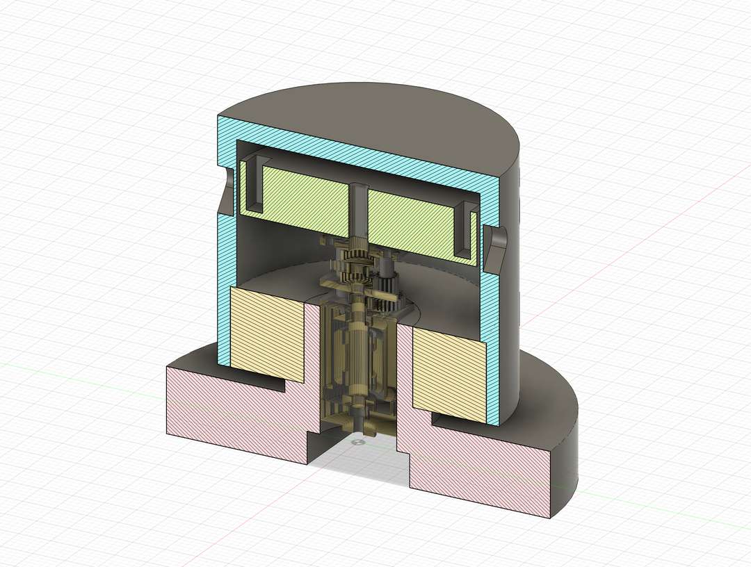
I quickly created a draft model of my object in Fusion in order to get an idea of the shape, form, and dimensions of my object. This allowed me to start to figured out how all the components might fit together and how that might change the overall form of the object.
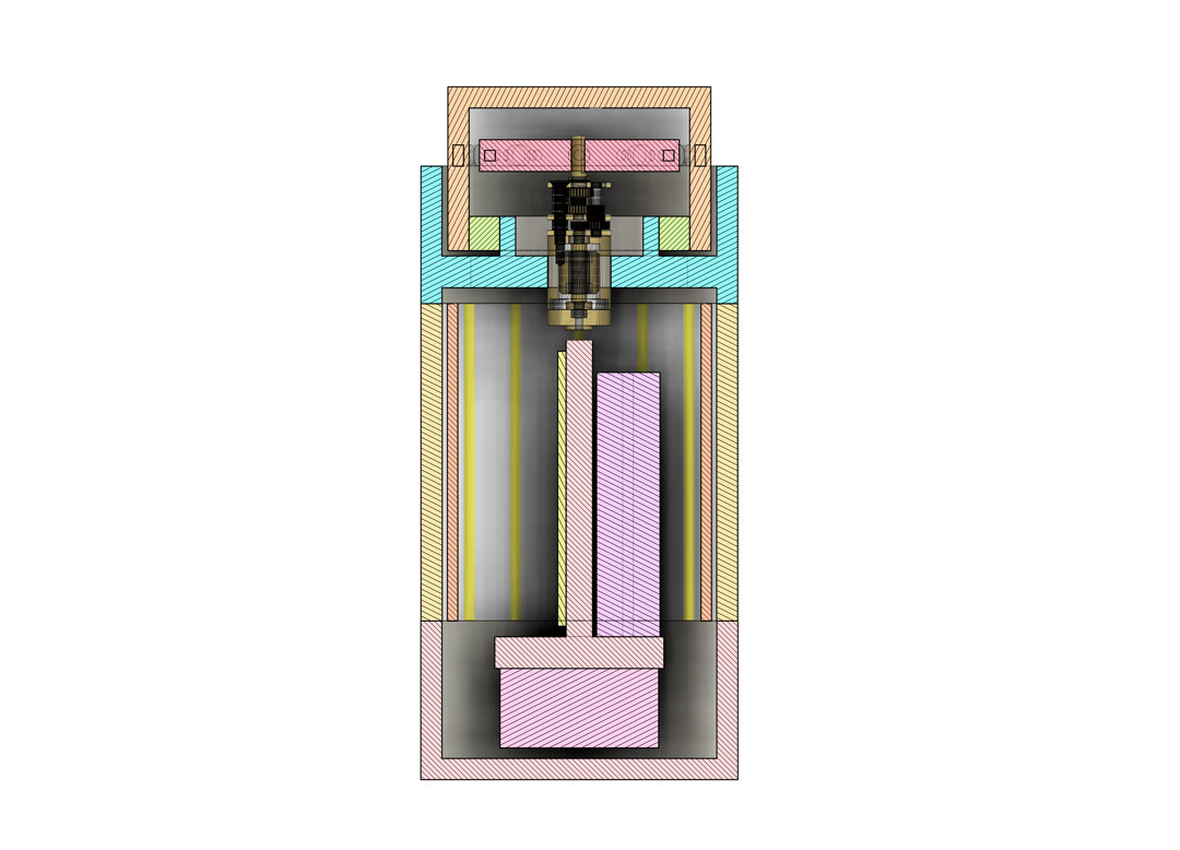
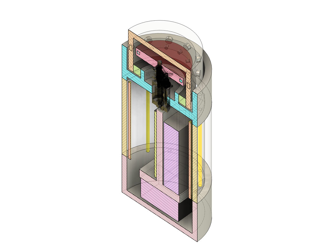
First system integration draft

System architecture

Diagram of the electrical system and the mechanical coupling. The battery bank has a separate USB-C charging input and USB-C power output to the XIAO. The main board has two separate MOSFETs — one for the LEDs, one for the motor. The hall effect sensor, LED filaments, haptic actuator driver, and speaker amp all live on their own small boards away from the main board.
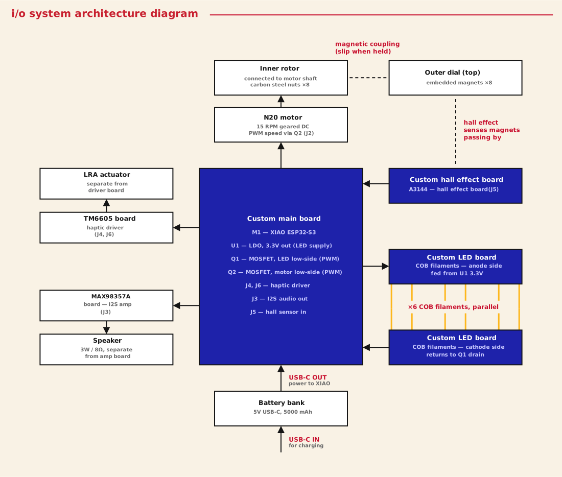
i/o system architecture block diagram: the battery bank has a separate USB-C charging input and a USB-C power output to the XIAO on the custom main board (XIAO ESP32-S3, LDO 3.3V regulator, and separate MOSFETs Q1 for LED and Q2 for motor). The hall effect sensor is on its own board mounted next to the outer dial magnets, feeding into the main board. The LDO 3.3V output feeds LED board A, the COB filaments span across to LED board B, which returns to the Q1 MOSFET drain on the main board. Q2 drives the N20 motor. The TM6605 haptic driver board is separate from the LRA actuator, and the MAX98357A amplifier board is separate from the speaker. A second, mechanical section below shows the motor shaft driving the inner rotor (carbon steel nuts), magnetically coupled without contact to the outer dial (embedded magnets), with the hall effect board sensing the magnets passing
i/o system architecture

Testing one part of the system

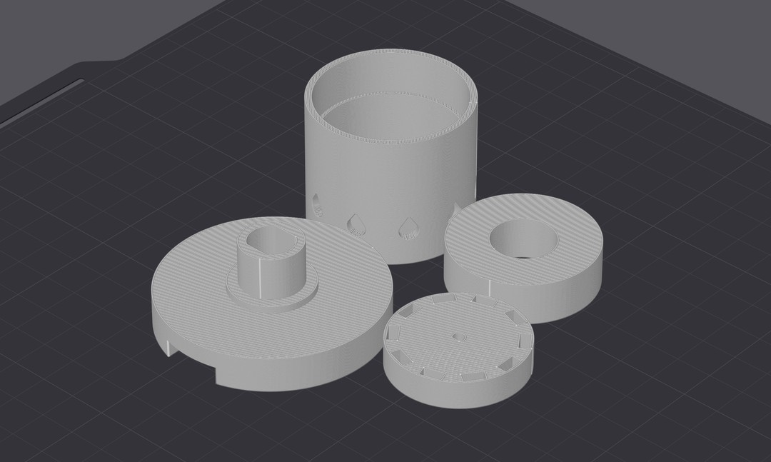
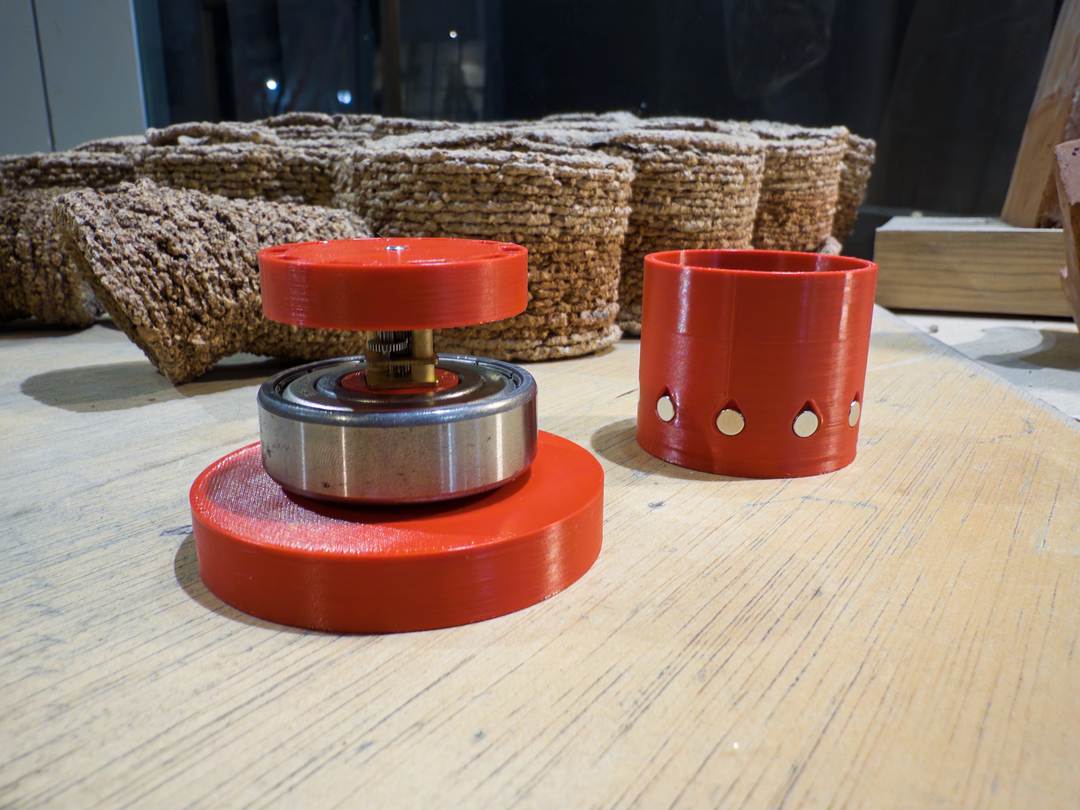
I quickly redesigned the magnetic differential to be able to print and test the effect. I used magnets on the outer dial and steel nuts on the driven inner rotor.
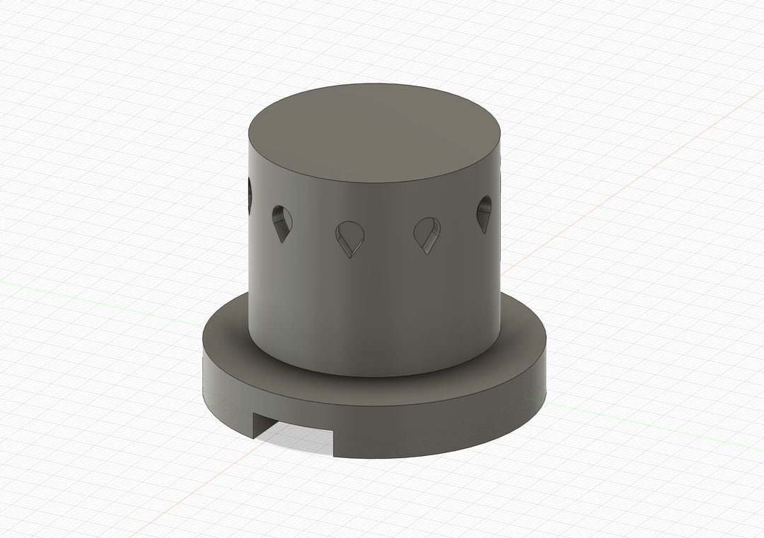
test dial model
test dial section view
test dial in the slicer
test dial assembly
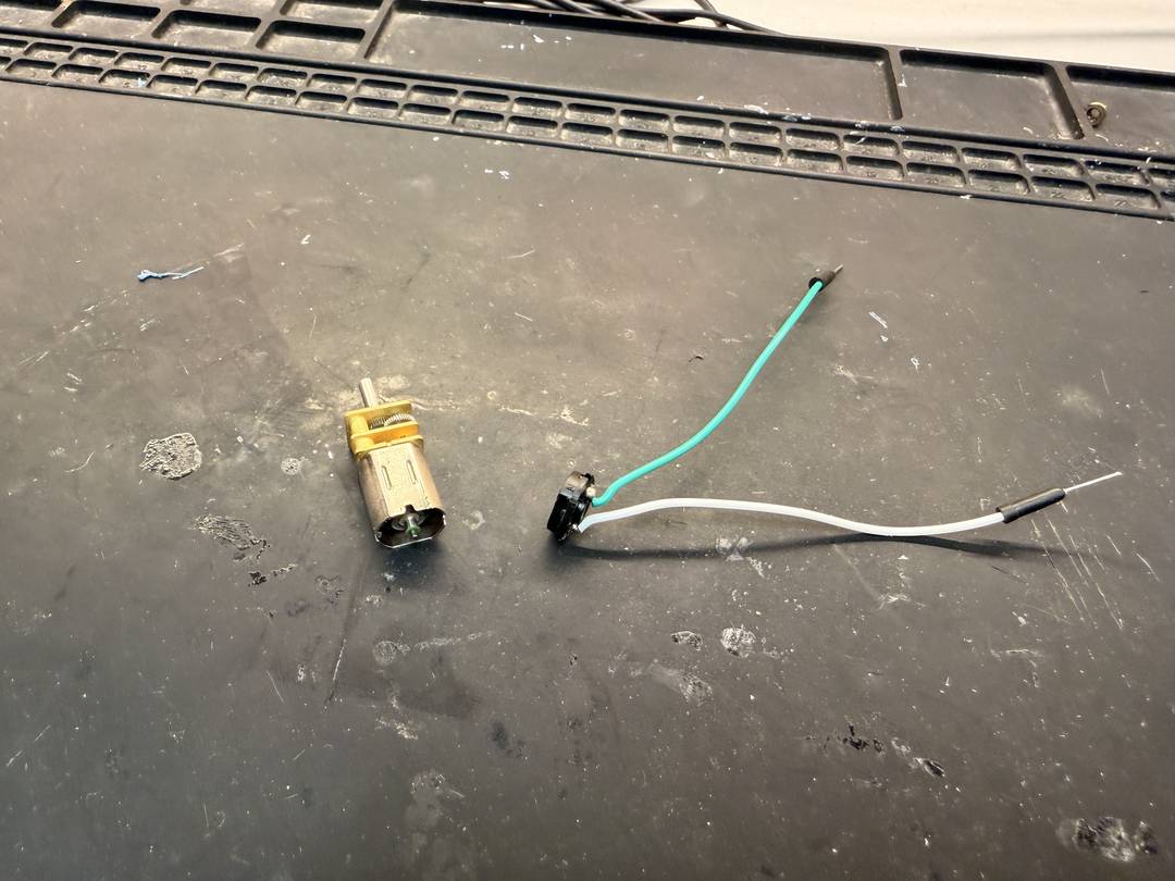
soldering motor wires
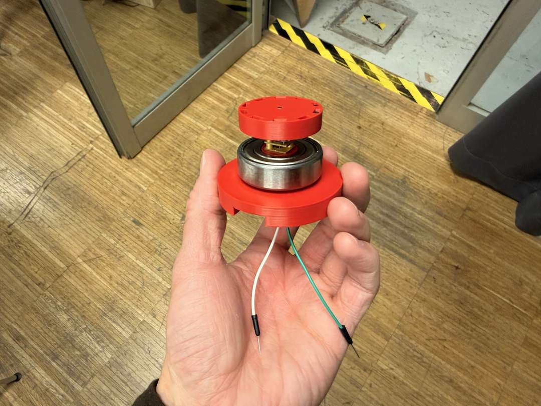
test dial assembled
test dial assembled, another angle

Getting more complex

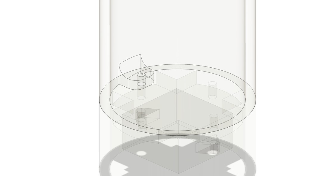
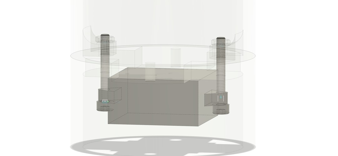
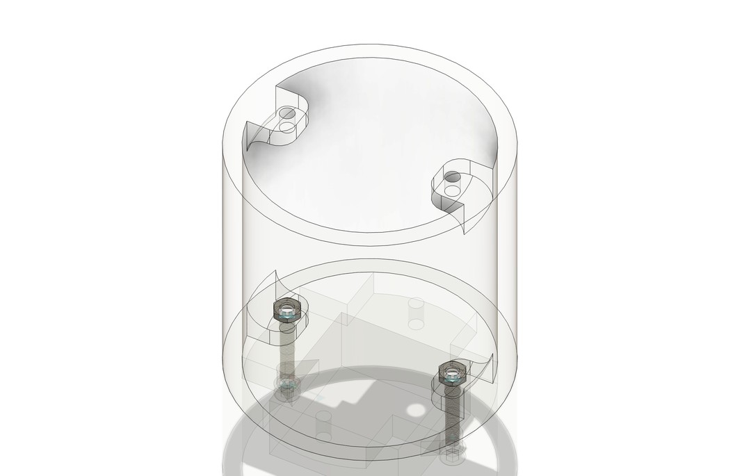
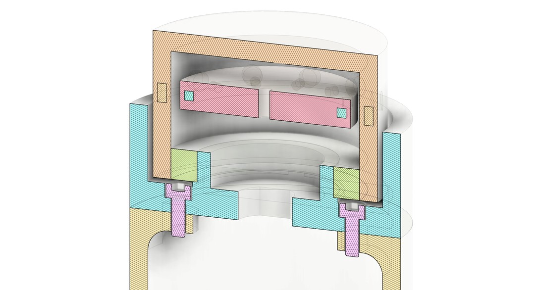
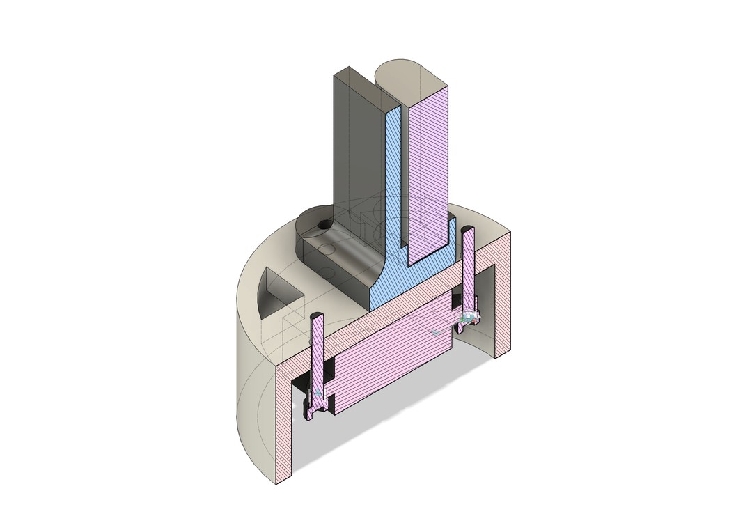
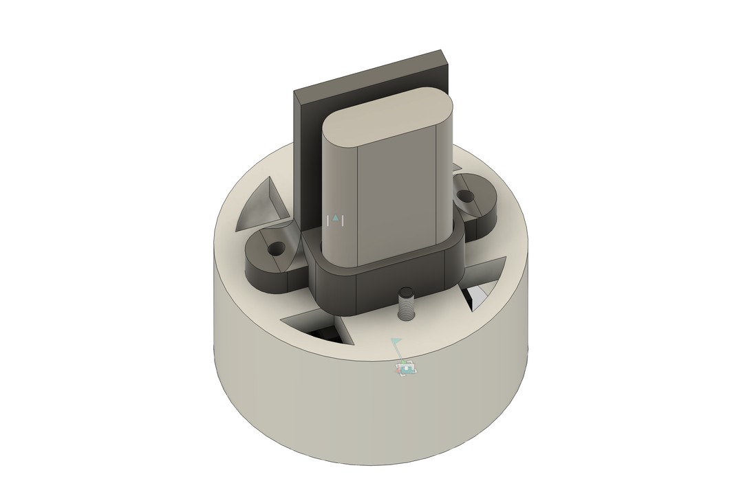
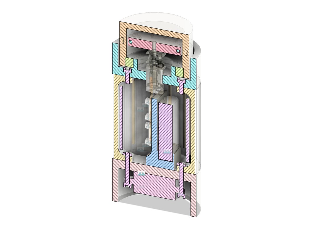
I started to redesign the parts of the system to mount together in a logical way. I added mounting tabs, mounting holes, and fasteners.
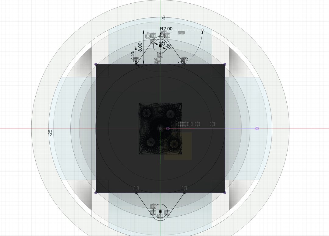
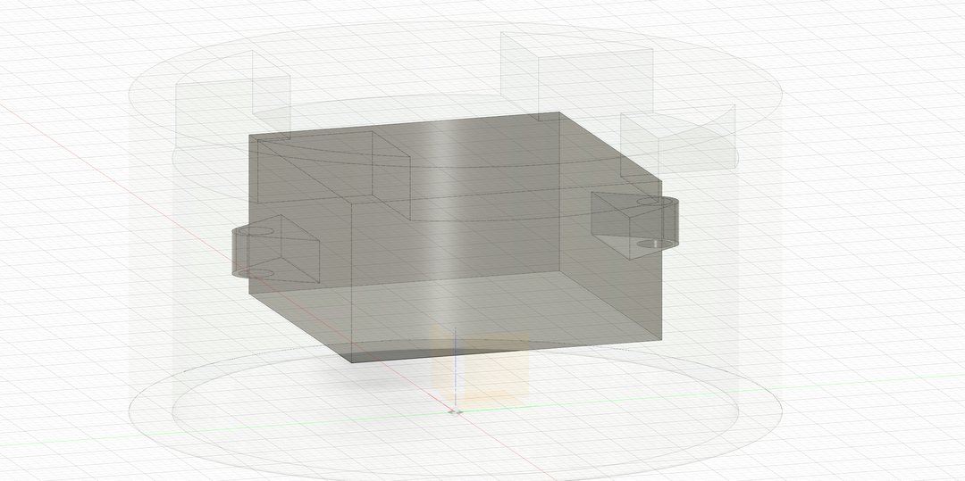
speaker mounts
speaker placement
middle section mounts, bottom
first set of mounting screws
middle section mounts, top
top part section view
battery mount, section
battery mount, another angle
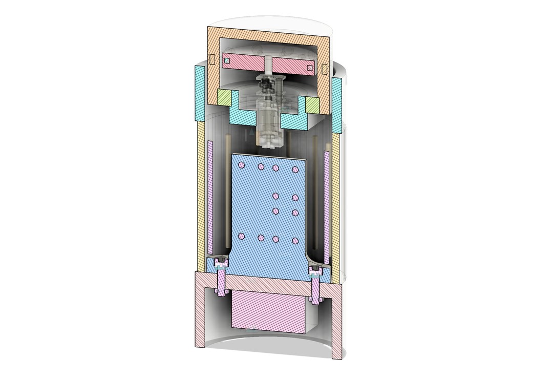
v2 section view, Y-axis
v2 section view, X-axis
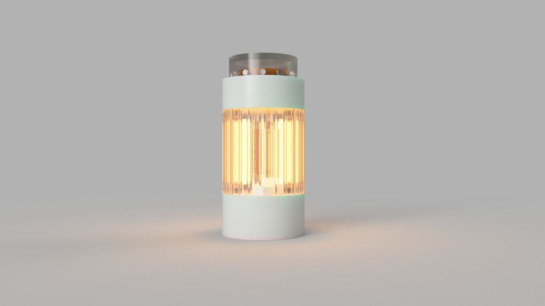
I/O draft concept rendering

Design files

Draft model (.f3z) Final model (.f3d) Magnetic differential test mechanism (.f3d) Main board KiCad project (.zip) LED + hall effect boards KiCad project (.zip)

Final system integration

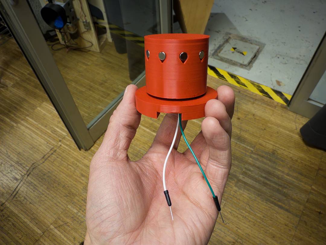
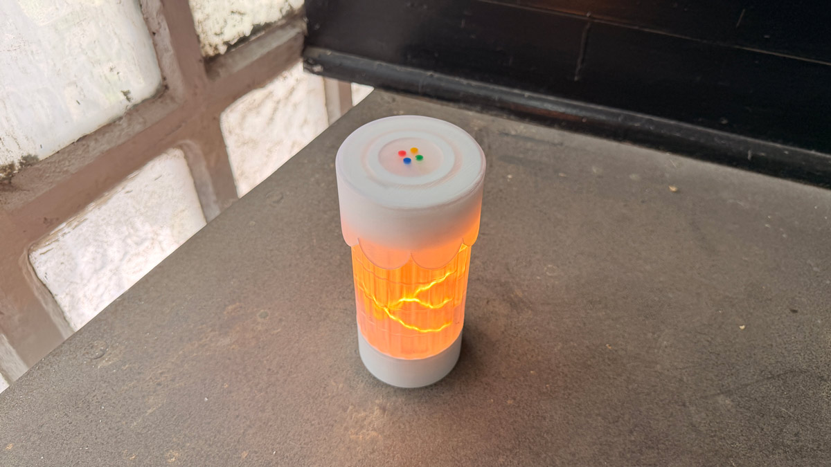
i/o final photo
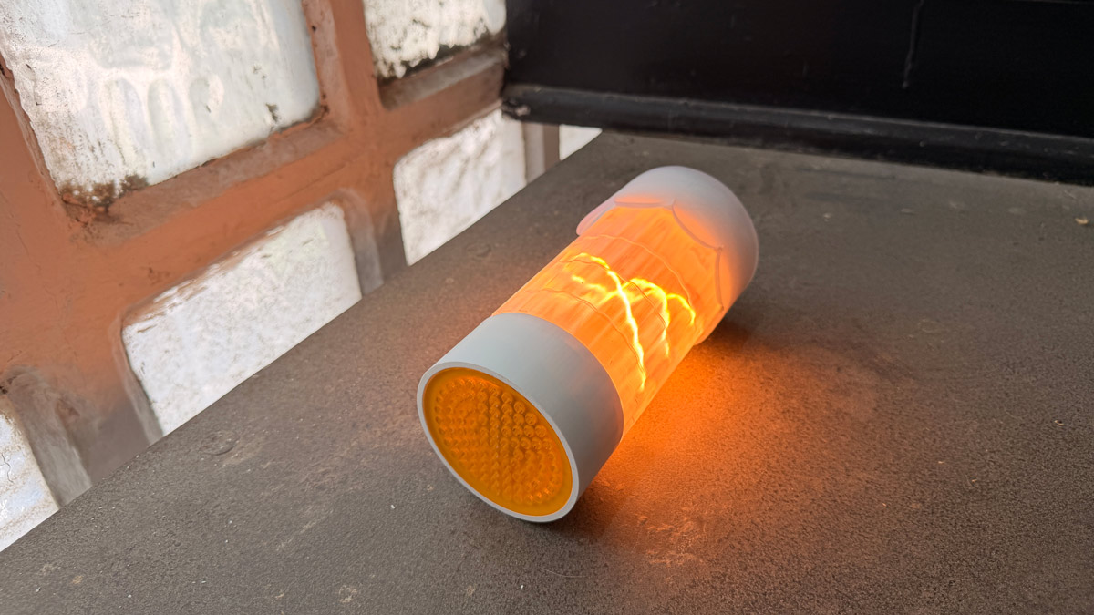
i/o final photo
Country roads...