Week 5. 3D Scanning and printing
Week Assignment
Group assignment:
-
Test the design rules for your 3D printer(s)
-
Document your work on the group work page and reflect on your - individual page what you learned about characteristics of your printer(s)
Individual assignment:
-
Design and 3D print an object (small, few cm3, limited by printer time) that could not be easily made subtractively
-
3D scan an object (and optionally print it)
Learning outcomes
-
Identify the advantages and limitations of 3D printing
-
Apply design methods and production processes to show your understanding of 3D printing.
-
Demonstrate how scanning technology can be used to digitize objects
Have you answered these questions?
-
Linked to the group assignment page
-
Explained what you learned from testing the 3D printers
-
Documented how you designed and 3D printed your object and explained why it could not be easily made subtractively
-
Documented how you scanned an object
-
Included your original design files for 3D printing
-
Included your hero shots
Studying the Characteristics of 3D Printers
3D Printers
We have two 3D Printers: The Bambu Lab A1 and The Bambu Lab X1 Carbon
The Bambu Lab A1
- is a compact and budget-friendly 3D printer developed by Bambu Lab, a company known for its cutting-edge advancements in 3D printing technology. Designed for beginners, hobbyists, and home users, it offers a seamless balance of user-friendliness and high performance.
Key Specifications and Features:
Printing Technology
- FDM/FFF:Uses melted filament to build objects layer by layer.
- Multi-Color Support: AMS Lite system enables seamless filament switching.
Print Area
- Build Volume: 256 × 256 × 256 mm—suitable for most home projects.
- Heated Bed: Improves adhesion and reduces warping.
Speed & Precision
- Print Speed: Up to 500 mm/s for fast prints.
- High Accuracy: Precision ensured by quality stepper motors and positioning.
Supported Materials
- Filaments: PLA, PETG, TPU, ABS, and more.
- Auto Calibration: Ensures consistent print quality.
AMS Lite System
- Multi-Color Printing: Supports up to 4 colors in one print.
- Auto Spool Switching: Simplifies multi-material prints.
Control & Connectivity
- Touchscreen: Intuitive and user-friendly interface.
- Connections: Wi-Fi, Ethernet, USB.
- Mobile App: Remote monitoring and control.
Safety & Convenience
- Enclosed Design: Reduces noise and enhances safety.
- Air Filter: Minimizes fumes from materials like ABS.
Bambu Lab A1 Calibration Guide
- Power on and connect to Wi-Fi.
- Open Settings on the touchscreen.
- Select Calibration and start the process.
- The printer will auto-level the bed, adjust the Z-offset, and test resonances.
- Wait 5–10 minutes, then you’re ready to print!
Material:
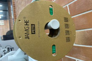
PETG (Polyethylene Terephthalate Glycol)
Brand: JAMG HE PETG is a durable and versatile 3D printing filament, widely favored by both hobbyists and professionals for its balance of strength, flexibility, and ease of use.
Specifications:
- Strength: High impact resistance with moderate flexibility.
- Printing Temperature: 230–250°C
- Bed Temperature: 70–80°C
- Adhesion: Excellent, adheres well to glue or PEI surfaces.
Key Advantages:
- Easier to print than ABS while offering greater toughness than PLA.
- Resistant to moisture and chemicals, making it suitable for various applications.
- Produces a glossy finish for a professional look.
Printing Tip:
For the Bambu Lab A1, use a print speed of 40–60 mm/s with cooling enabled for the best results.
Group and Individual Assignment
The Bambu Lab A1
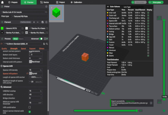
The Bambu Lab Print
This week I worked on defining my final project idea and started to getting used to the documentation process.
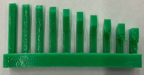
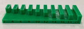
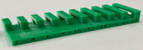
We have evaluated the overall Overhang Performance, conducted a Long Overhang Test, and assessed both Extrusion Consistency and Bridging Performance.
Print Quality Overview
By using The Bambu Lab A1, we have tested the overall print quality.
The overall print quality is satisfactory, with strong layer adhesion and relatively smooth surfaces at lower overhang angles. However, as the overhang angle increases, sagging and deformation become more prominent, indicating that cooling settings may require optimization to maintain structural integrity.
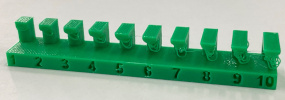
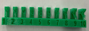
Overhang Performance
- Lower Angles (2° - 10°): Minimal defects, prints well.
- Medium Angles (12° - 16°): Slight sagging observed.
- Higher Angles (18° - 20°): Noticeable deformation, suggesting the need for improved cooling and reduced print speeds.
Suggested Enhancements for Overhangs:
- Increase cooling fan speed to solidify layers faster.
- Lower print temperature slightly to minimize sagging.
- Reduce print speed at higher angles for better stability.
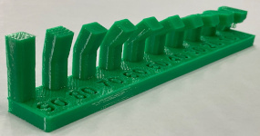
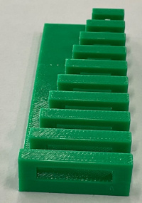
Long Overhang Test
In extended overhang tests, bending becomes more evident at steeper angles. This suggests:
- Print speed may be excessive, preventing proper layer formation.
- The filament does not cool sufficiently before the next layer is deposited.
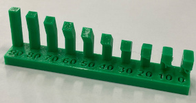
Recommended Adjustments:
Increase fan speed to accelerate filament cooling. Lower printing temperature to minimize sagging. Use support structures for extreme overhangs.
Extrusion Consistency
Some inconsistencies in extrusion were detected, potentially caused by:
- Incorrect flow rate settings.
- Fluctuating hotend temperatures.
Solutions:
- Adjust the extrusion multiplier for optimal flow.
- Ensure smooth filament feeding to prevent under-extrusion.
- Maintain stable hotend temperature to avoid variations.
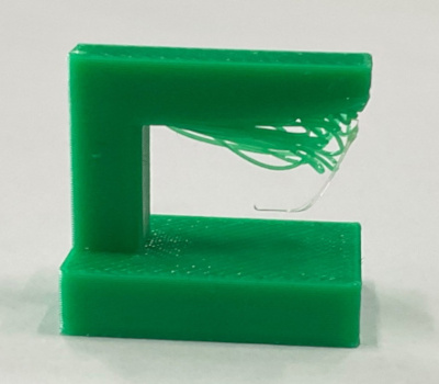
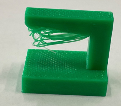
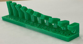
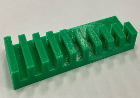
Bridging Performance
The unsupported overhang test revealed:
- Significant stringing and filament drooping.
Weak bridging performance, particularly in horizontal sections.
Recommended Improvements:
- Lower print temperature to reduce filament sagging.
Increase cooling fan speed to improve bridge formation. Adjust retraction settings to minimize stringing.
3D Printing Practice
Designing a Helical Wind Turbine and Gear System in Onshape
For the 3D printing assignment, I wanted to design parts related to my final project idea: a renewable-energy-powered autonomous catamaran. Since the full boat is complex, I decided to start with smaller mechanical subsystems that can later become part of the boat.
I focused on two main elements: - an Archimedes-style helical wind turbine and - a spur gear mechanism that can increase rotational speed before transferring motion to a generator.
I used Onshape to model these parts because it allows parametric design, precise dimension control, and easy modification of sketches, features, and patterns. The goal of this exercise was not only to create a visual model, but also to understand how 3D forms can be generated from sketches, curves, lofts, extrusions, circular patterns, and custom gear features.
Helix-cylinder - 3D Print
Creating the helix curve
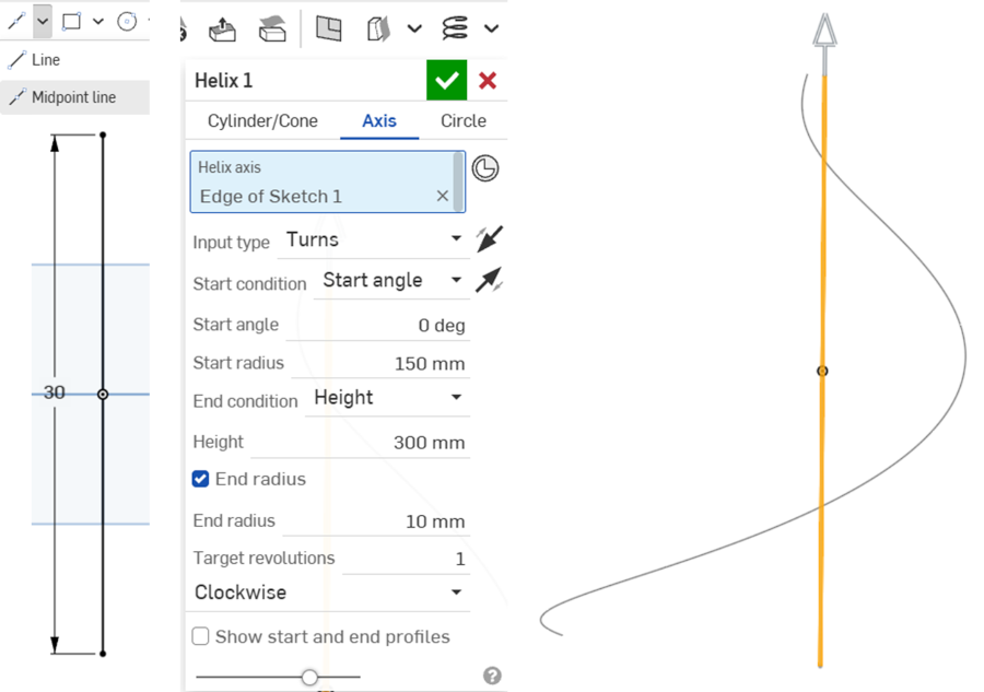
In the first step, I created the main helical path for the turbine blade and started by drawing a vertical reference line that became the axis of the helix. Then I used the Helix tool in Onshape and selected the sketch edge as the helix axis and set the start radius to 150 mm, the height to 300 mm, and the target revolution to 1 turn. I also adjusted the end radius to 10 mm, which made the curve gradually reduce toward the top.
This step was important because the helix curve defines the main shape and movement of the turbine blade. Instead of making a simple straight blade, I wanted to create a twisted form similar to an Archimedes helical turbine.
By controlling the height, radius, and number of turns, I could define the overall proportions of the turbine and prepare the base geometry for the next modeling step.
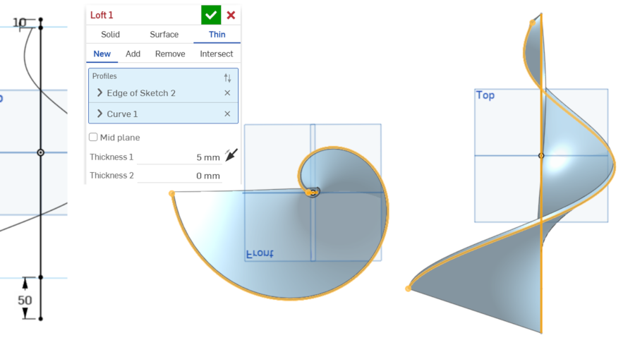
Creating the blade surface with Loft
After creating the helix curve, I used the Loft tool to generate the first blade surface and selected the profile from the sketch and connected it with the helical curve. In this step, I used the Thin option and set the blade thickness to 5 mm. This allowed me to create a surface-like blade with real printable thickness rather than only a visual surface.
This stage helped me understand how a 2D sketch can be transformed into a 3D twisted blade.
The loft operation followed the curved helical path and created a smooth spiral surface around the central axis. This was one of the most important steps because it converted the basic helix idea into a real blade geometry that can later be 3D printed and tested.
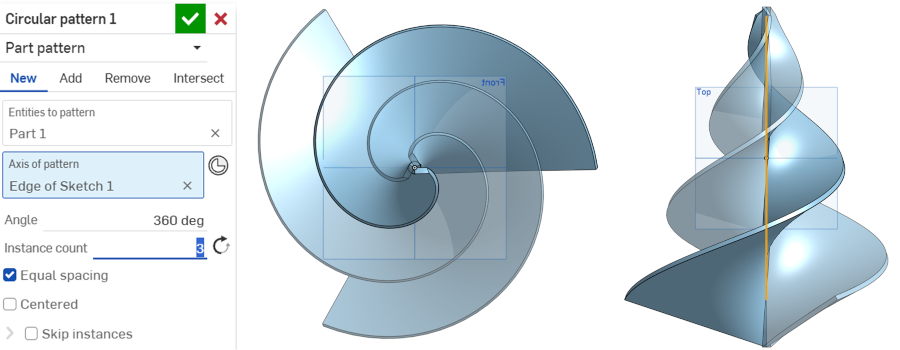
Using circular pattern to create multiple blades
After creating one blade, I used the Circular Pattern tool to duplicate it around the central axis and selected the first blade as the part to pattern and used the main vertical axis as the axis of rotation. I set the circular pattern to 360 degrees with 3 instances, so the turbine would have three equally spaced blades.
This step was useful because it allowed me to create a balanced turbine structure without manually drawing each blade.
A three-blade design can provide better symmetry and smoother rotation. In Fab Academy, this is also a good example of parametric and repeatable design: I only needed to model one blade correctly, and then the software generated the other blades with equal spacing.
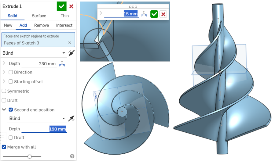
In the next step, I added a central cylindrical shaft to the turbine and created a circular sketch at the center and used the Extrude tool to make the cylinder pass through the turbine body.
I set the extrusion depth in two directions, using values around 230 mm and 190 mm, so the shaft could extend through the model and support the rotating structure.
The central cylinder is important because the turbine blades need a mechanical support for rotation. In a real prototype, this part could be connected to a bearing, axle, or generator shaft. This step helped me think not only about the shape of the turbine, but also about how the part could be assembled and used in a working mechanical system.
Spur-gear - 3D Print
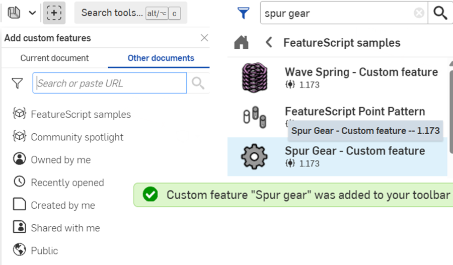
Adding the Spur Gear custom feature
For the gear system, I first added a custom feature in Onshape and opened the Add custom features menu, searched for Spur Gear, and added the Spur Gear custom feature to my toolbar. This feature is useful because manually drawing correct gear teeth is difficult and time-consuming, especially for beginners.
Adding this feature helped me quickly generate accurate gear profiles by changing parameters such as number of teeth, module, pitch circle diameter, pressure angle, and depth. This was important for my project because
I want to use gears to increase the rotational speed from the wind turbine before transferring motion to a generator.
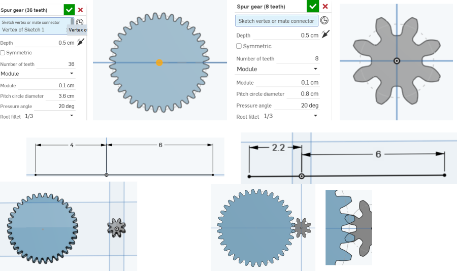
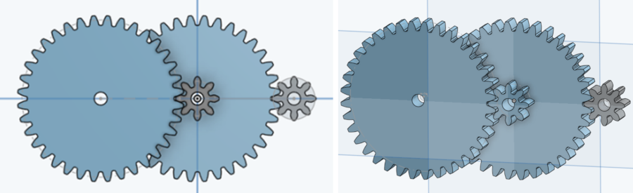
Creating the first pair of spur gears
After adding the Spur Gear feature, I created two gears with different numbers of teeth. The larger gear had 36 teeth, and the smaller gear had 8 teeth. Both gears used the same module value, which is important because gears must have compatible tooth sizes to mesh properly.
I also used a 20-degree pressure angle, which is a common gear design parameter.
I placed the gears on the same sketch plane and adjusted the distance between their centers. The purpose was to create a basic gear ratio. When a large gear drives a smaller gear, the smaller gear rotates faster.
This matches my final project idea, because the wind turbine may rotate slowly, and the gear system can help increase the rotation speed for better generator performance.
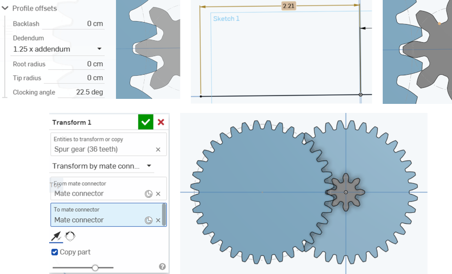
Adjusting gear mesh and spacing
In this step, I worked on the spacing between the gears and checked how their teeth fit together.
I adjusted the center distance and looked closely at the contact area between the large and small gears and I also checked gear settings such as backlash, dedendum, root radius, and tip radius. These parameters affect how smoothly the gears can rotate together.
This step showed me that gear design is not only about creating teeth visually. The gears must be positioned correctly so they can mesh without too much friction or interference.
If the gears are too close, they may jam. If they are too far, the teeth may not engage properly. This helped me understand why mechanical design requires both geometry and testing.
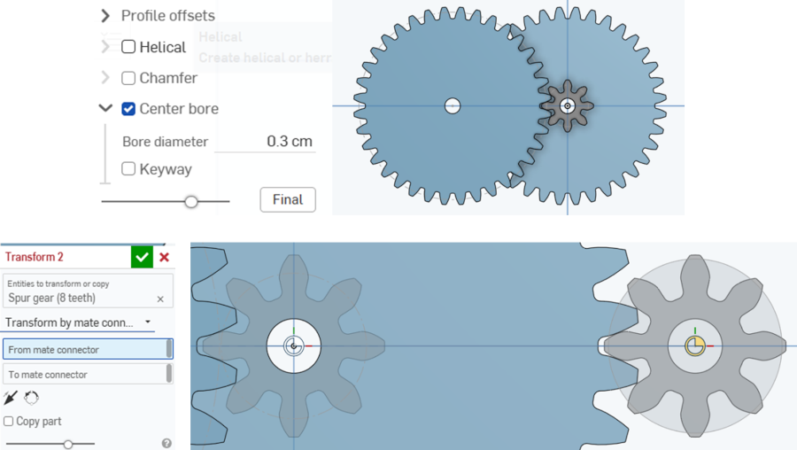
Adding center bores and positioning gears
After creating the gears, I added center bores to the gear models and used the Center bore option and set the bore diameter to around 0.3 cm. The holes are important because gears need to be mounted on shafts or axles. Without a center hole, it would be difficult to connect the gear to the turbine shaft or to another rotating mechanism.
I also used the Transform tool with mate connectors to copy and position gears more accurately.
This helped me align the gear centers and prepare a more complete gear train. By copying and transforming the gear parts, I could test different positions and understand how the gears might be arranged in a real prototype.
Final gear train concept
In the final gear design step, I created a simple gear train with multiple gears. The design included large gears and small gears positioned so that motion could be transferred from one gear to another.
This layout demonstrates the idea of increasing rotational speed by using a gear ratio. The large gear can receive motion from the turbine, and the smaller gear can rotate faster and transfer motion toward the generator.
This design is still an early concept, but it helps me visualize how the mechanical power transmission system can work. For the next stage, I need to check tolerances, shaft positions, gear thickness, and 3D printing limitations.
I also need to print test gears and physically check whether they rotate smoothly. This is important because a gear system may look correct in CAD, but real performance depends on printing accuracy, material, clearance, and assembly.
3D Scanning Practice
3D Scanning Practice
I have scanned a green apple with WIDAR 3D Scanning app on IPAD.
Conclusion
These tests provide valuable insights into the printer’s performance and highlight areas for improvement. To enhance print quality, consider:
- Adjusting slicer settings to enable support structures for extreme overhangs.
- Lowering print speed to improve accuracy.
- Refining cooling parameters for more stable overhangs.
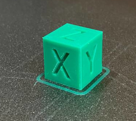
Learning outcomes
In this week’s 3D Scanning & Printing work, I documented the Bambu Lab A1 setup (AMS workflow, slicer profiles, safety and calibration steps) and ran a PETG process study using standard test models—overhang towers, long-bridge tests, and an XYZ calibration cube—to evaluate extrusion consistency, surface finish, and cooling. Results showed clean walls but sagging on steep overhangs and bridges, plus mild stringing—typical PETG behavior—so I tuned slicer parameters: lowered nozzle temperature, increased part cooling, slowed print speed on bridges, added supports for >60° features, and refined retraction/flow (extrusion multiplier) to remove under/over-extrusion. I also captured a 3D scan of a green apple with the WIDAR iPad app, cleaned the mesh (hole fill/decimate/smooth), scaled and oriented it in the slicer, and printed it to validate the full pipeline from capture to object. The combined tests clarified how material choice, cooling, and motion settings interact, and produced a practical checklist for PETG: stable hotend temps, adequate cooling on bridges, conservative speeds for difficult geometry, and calibrated flow/retraction to control stringing.