Week 08 - Electronics Production

Group assignment:
• Characterize the design rules for your in-house PCB production process: document feeds, speeds, plunge rate, depth of cut (traces and outline) and tooling.
• Document the workflow for sending a PCB to a boardhouse
• Document your work to the group work page and reflect on your individual page what you learned
Individual assignment:
• Make and test a microcontroller development board that you designed
Group assignment
For this week’s Group assignment, I teamed up with my fellow Fab Academy buddy Haw Ren to test and use the Stepcraft 420, a desktop CNC milling machine.
The documentation for our Group assignment can be found here.
Individual Assignment
This week’s individual assignment was not off to a good start. The board that I had designed from Week 06 (Electronics Design) was too large and I had to create another one. It is a good refresher, but I had to start from scratch again. And I did it wrong again! I had milled out the board but only discovered the flaw in my design after my instructor spotted it when I soldered the first component on. There were multiple issues with traces routed wrongly so that they were unable to form complete circuits. One example of this was the switch was not connected to a signal pin so the switch would not do anything when pressed.

So here is my third attempt. I am beginning to feel discouraged at this point but I have to push on.
Generating the NC files from PNGs
To generate the NC files, I output PNG files for:
1. Traces
2. Outline
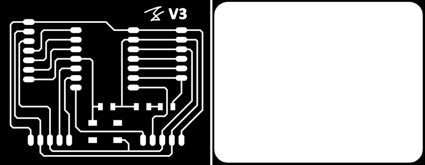
I then take those PNG files into mods to generate the NC files. The process has been covered in Week 06.
I used the settings from my colleague and former Fab Academy student, Willie Tay:
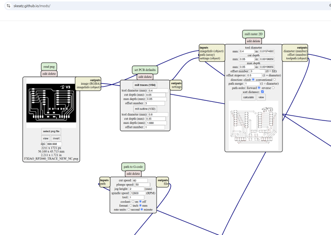
• Mill Traces - By Default, the Mill Traces is 1/64 and this is for the milling of the circuit path. (for milling the path!)
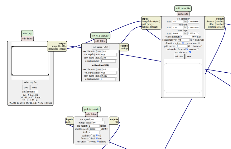
• Milling Outline - By Default, the Mill Outline is 1/32 and this is for the milling of the circuit board and holes profile. (Select this for milling the circuit board outline)
• Cut Depth - This is the depth of each mill and for Mill Traces, the depth should be around 0.05mm while Mill Outline, it should be around 0.35mm
• Max Depth - This is the maximum depth you want to mill and for Mill Traces, the depth should be around 0.05mm while Mill Outline, it should be around 1.68mm (Thickness of the Copper Board)
• Offset Number - This is number of times that the milling path will travel and for Mill Traces, the offset number should be 3 times while for Mill Outline, it should be only 1 time
• Cut Speed - This is the speed of the CNC router and by default, it should be at 60 mm/min.
• Specific Speed - You may adjust the specific speed that your machine is running - Our StepCraft CNC runs at 12,600 rpm so I am using 12,600 rpm instead of 11,000 rpm or 12,000 rpm.
• Format & Rate Units - Remember to select the correct Format & Units that you are using for the milling i.e 60 mm/min = 1 mm/s
Below are my settings in Mods:
Trace settings:
Outline Settings:
Board Production
The detailed steps for board production can be referenced from our Group Assignment.
Here is a summary of the steps:
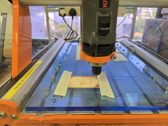
Fixturing
This step is to hold the workpiece down when milling. All that is needed is to use double-sided tape (as seen below) to secure the workpiece to the milling bed and then use masking tape as an additional measure.
Milling the traces
Using a 30 deg 0.1 mm V-Bit engraver, load in the NC file for the traces, and commence the process for milling the traces.
Milling the Outline
When the CNC machine has finished milling the traces with the engraver, change out the tool bit to an endmill to start cutting the outline.
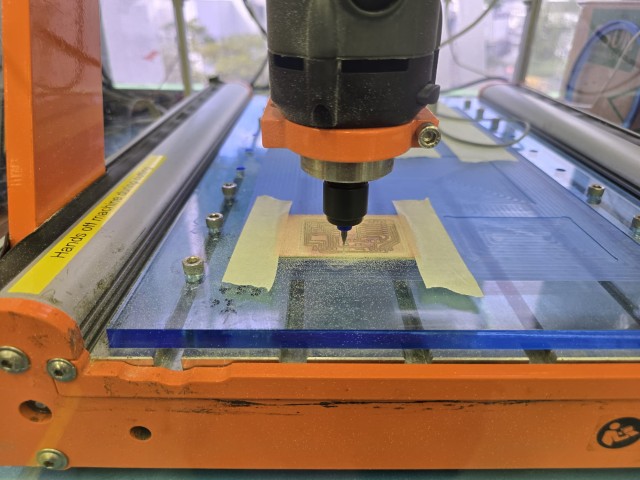
Once the outline is milled, the workpiece can be removed and cleaned up. The double-sided tape might leave behind some sticky residue. In my case, I cleaned it off with Isopropyl alcohol (IPA). Before soldering, I also washed the board with soap water. With that done, I layout my board next to the components and prepare to solder the components to the board.
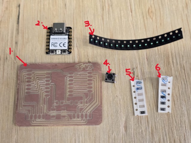
1. Board
2. XIAO RP2040
3. LED (Blue colour)
4. Push button switch
5. LED Resistor (1kOhm)
6. Switch Resistor (10kOhms)
In particular, the LED and the resistors are extremely small, and extra care needs to be given to them to be placed correctly. To a beginner (with questionable eyesight) like me, they all look extremely similar. To help me organize the parts, I used my camera zoom to take photos of the tiny components and had this handy Post it note to refer to when soldering.

The image shows the photos I took of the components zoomed in. I noted the number markings on the resistors (LED resistor with number 1001 and the Switch resistor with number 105), as well as the direction of which the LED should be laid (from + to -). Resistors can be laid in either direction.
IMPORTANT!!! This information above about resistor numbers is wrong and requires correction. It was only discovered when the board failed to work. Please refer to the Troubleshooting section for the corrected information.
Soldering components to the board
At this point, I start soldering the components to the board.
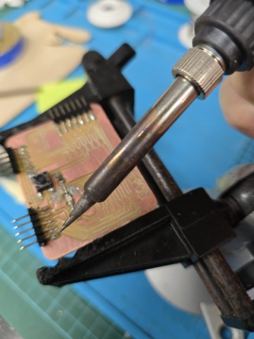
I recommend watching these 2 short YouTube videos before the soldering process:
iFixit's Soldering 101: Beginners Guide
Using Flux | Soldering Basics | Soldering for Beginners
They really helped me to understand what all the equipment was for, and what I should use.
After some time, I soldered all the components to the board. Still, there were problems aplenty…
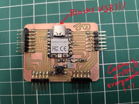
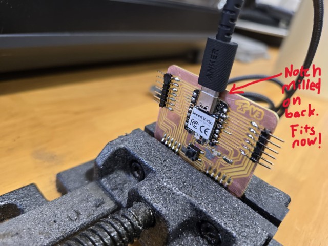
• Clearance for USB cable - The board did not have enough clearance to allow the USB cable to connect to the XIAO RP2040
• Continuity Errors - There were continuity errors on many of the connections.
Here is how I rectified the errors:
• Clearance for USB cable (Rectification) - I used a Dremel to manually mill off enough of the board to give enough clearance for the USB cable to connect. It was a brute force option but I had little choice due to time running out. The USB cable can now be connected to the XIAO RP2040.
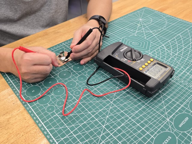
• Continuity Errors (Rectification) - I used a multimeter to check for the continuity of all the traces and connections, and then addressed the points of continuity breakage by re-soldering the joints. In had a difficult time try to get continuity to the pins of the XIAO RP2040 - I found it useful to use the soldering iron to heat up the pins and allow the solder to melt and go through the pin hole.
Testing the board
With the board completed, I use this simple programme to test my board:
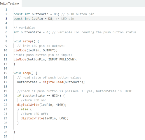
The programme is such that if the board is working, pressing the push button will light up the LED.
And... my heart sank when it failed to light up. This brings us to the next section, Troubleshooting
Troubleshooting
Immediately when my board failed, I tried the programme on my Fab Academy Buddy, Haw Ren’s board and his board lights up. This means that the code works, and the problem lies with the board. Since the problem lies with the board, I start checking the continuity again and it seems fine.
At this point, I had no idea what was wrong, and I needed more experienced eyes to look at the problem. Cue my colleagues Louis and Steven, and they identify that I have placed the direction of the LED wrongly. I then realized that in Eagle, the direction of the LED on the schematic may not be the same when routed on the board. This was my first mistake. I had assumed that the component would line up the same way on the board (e.g. L to R on schematic does not mean L to R on the board).
Steven teaches me how to use the hot air gun to remove the LED and correct its direction.
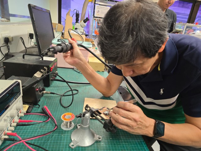
This was when Steven spotted another two mistakes on my board – Both resistors have the wrong value.
What I had:
LED resistor with number 105 and the Switch resistor with number 1001
What it should be:
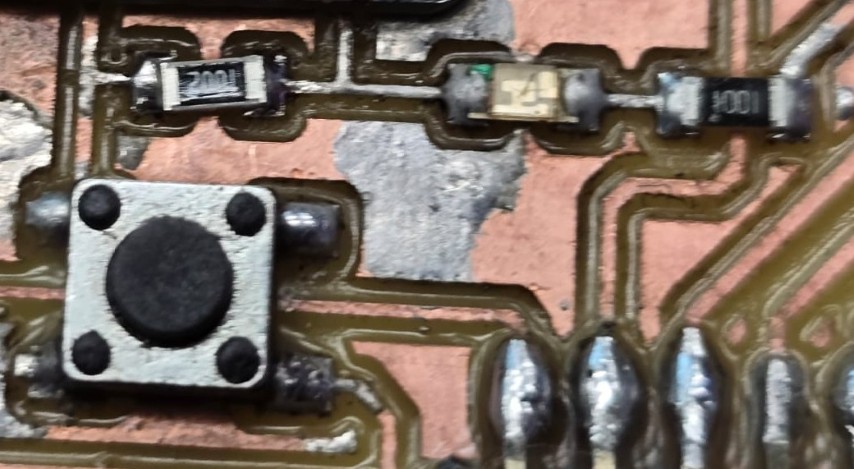
LED resistor with number 1001 and the Switch resistor with number 1002
Below is an explanation of how to read the resistor values correctly (Thanks Steven!):
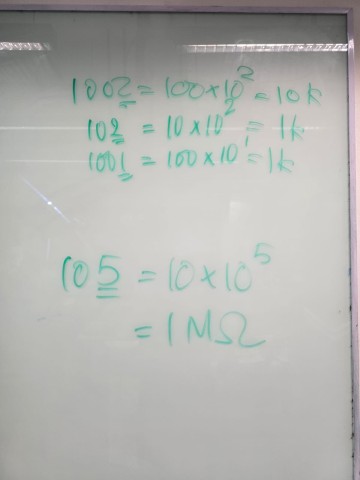
I then replaced the resistors with the correct ones. This involves using the hot air gun to soften the solder, removing the wrong resistors, and then soldering the correct resistors onto the board.
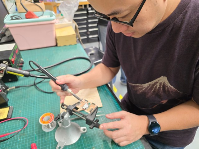
Once done, I check the continuity of the newly soldered components. The continuity is all good, and I proceed to test the board with the push button programme again.
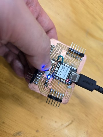
This time, it works!!! I breathed a sigh of relief and for a while, the world seems okay again.
Conclusions/Reflections
I felt like I went the distance and survived being pummelled repeatedly by the cruel fists of electronics production. I will not be surprised if the next season of Squid Game has a game that got the participants to make an electronics board.
Regardless of my struggles, I learnt many things this week and I am happy to have gotten my board to work. I thank the colleagues and instructors that came to my aid when I really could not help myself. There are still many things I do not know about electronics, but as long as I keep getting up and moving forward, I will improve.
Files
This concludes this week’s assignment.
