Week 08 - Electronics Production

Group Assignment:
• Characterize the design rules for your in-house PCB production process: document feeds, speeds, plunge rate, depth of cut (traces and outline) and tooling.
• Document the workflow for sending a PCB to a boardhouse
• Document your work to the group work page and reflect on your individual page what you learned
Our Desktop CNC machine
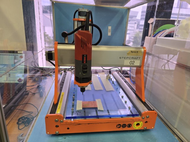
The CNC machine that we used is the Stepcraft 420 which has the following features:
• Integrated modular control electronics for an easy connection to the computer via USB or parallel interface
• MDF machine table with aluminum T-slots, optionally available with aluminum T-slot table
• 2A Sanyo Denki stepper motors
• Y-axis driven by two stepper motors
• All-Steel Motion System™ out of hardened steel, known from the STEPCRAFT Q-Series
• 4-track roller guidance
• Ready-to-use track rollers, no Adjustment of preload required
• High-strength profiles on all axes for optimal distribution of Forces and particularly high torsional rigidity
• igus® Energy chains on all axes
• Standard Ø 43 mm tool holder enables the use of third-party devices (if necessary, with Adapter)
• Optimized, integrated clamping system (clamping bars) for plate materials up to 15 mm thick
• igus® precision threaded lead screws • Y-axis with Silicone seal to protect against dirt
• Two T-slots in Z-axis to attach additional accessories
• Up to seven crossbars along the Y-axis for an extremely precise and evenly stiff machine bed
• Easy-care and wear-resistant surfaces (powder coating, anodizing)
• Made in Germany • 5 years manufacturer's warranty
• Dimensions (X, Y, Z): 443 mm x 600 mm x 546 mm
• Working Space (X, Y, Z): 298 x 415 x 132 mm
• Clamping Surface (X, Y): 316 x 499 mm
Safety
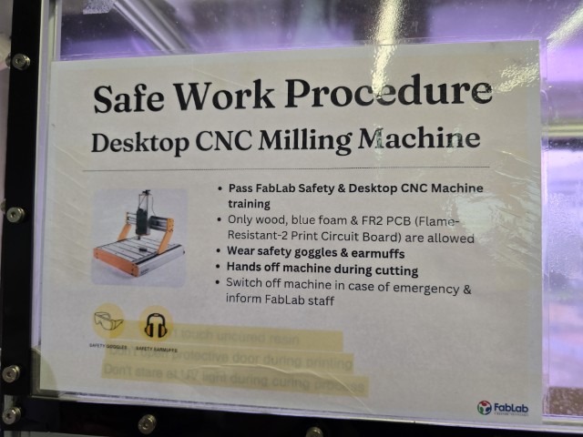
We have a sign in our lab that reminds us of the safe work procedures to note before using the Desktop CNC. The only thing that we would like to add is to be careful when handling the tool heads as they are very sharp.
Different tool bits (and what they do)
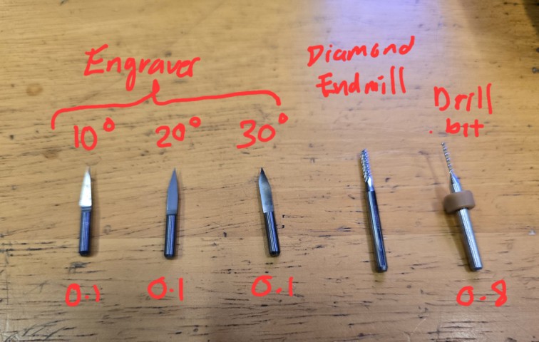
Before Milling it is very important to prepare the files in G-code for the different types of tool bits and settings. There are different tool bits that do different things. Here are some that we were introduced to:
• Engravers – For engraving
• Endmills – For through cutting
• Drill bits – For drilling holes
As a general rule we have this lab:
• Traces: we can use a 4mm End Mill Flat or 0.1 mm V-Bit engraver
• Drills: 0.8 mm End Mill Flat
• Outline: 0.8 mm End Mill Flat
The file of Drill and Outline can be together as they have the same settings, but just to have more control we separate the files just in case we want to change the drills, especially when we have big pins the end mill has to be bigger.
We create the G-Code in Mods and then we transfer it to the CNC PC and open the files, the first to be milled are the traces, then the drills, and lastly the Outline.
For the traces our lab generally uses the V-bit in 0.1mm there are three angles, 10, 20, and 30. These angles influence the thickness of the trace, the deeper that we go with it the thicker the trace becomes.
Fixturing process
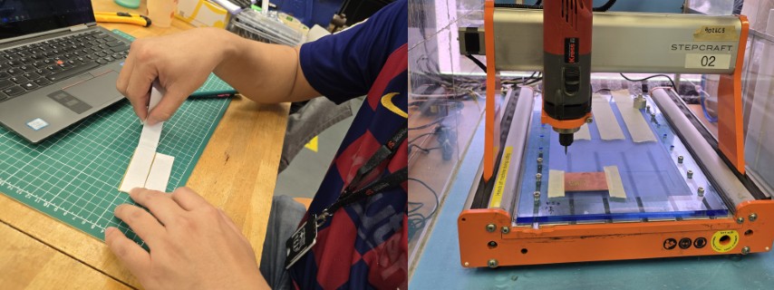
The process of fixturing is straightforward – Secure the job by using tape to hold it down.
Attaching the tool head
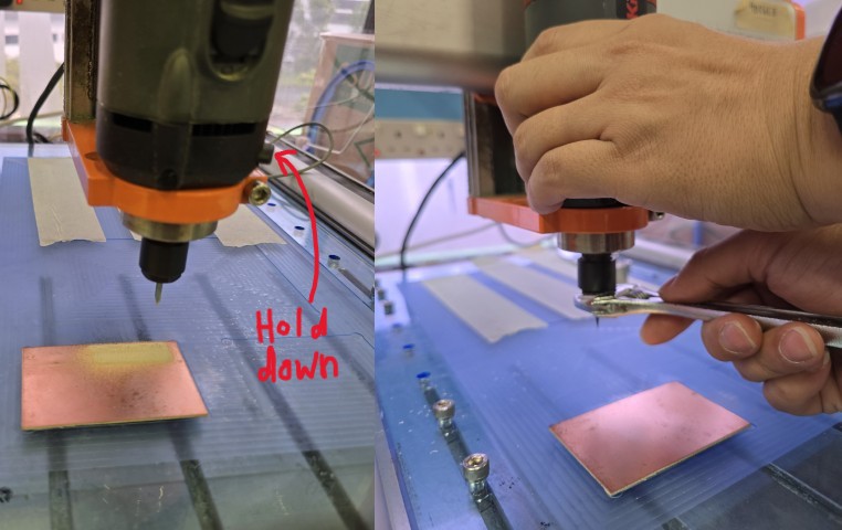
We changed the tool bit to a new engraver. To remove the old tool, hold down the button shown in the picture above to prevent the router head from rotating, then apply a force with a spanner in the opposite direction. Next, remove the collet (the thing connecting the tool bit to the spindle) from the router.
When the collet is out, swap the old tool bit for the new one, and reattach it to the spindle.
Our instructor Steven explained to us that we need to be careful not to use too much force when fastening the collet to the router, as this can cause damage to the parts, reducing its ability to hold bits properly and leading to uneven clamping or slippage.
Setup process
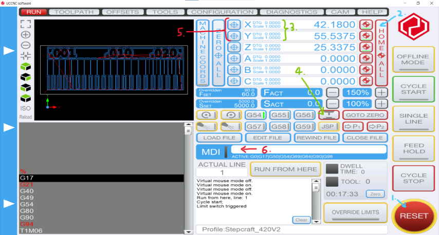
We use the STEPCRAFT software and set up our milling job by following these steps:
1. Click RESET to refresh the software
2. Click on HOME ALL to send the spindle to the left-back corner of the machine. This is where the zero point is.
3. We then manipulate the router manually (X and Y) using the computer arrow keys to where we have previously secured the job. We do not move the Z-axis at this point of time. As long as it is not knocking into anything, there is no need to adjust it until the next step.
4. Once the spindle is directly above the job, we put the sensor under it to have the “Real” Zero of the Z-Axis. We hit the button (red outline with graphic of the tool above the sensor). The spindle will go down to touch the sensor and this will provide us with the Z dimension.
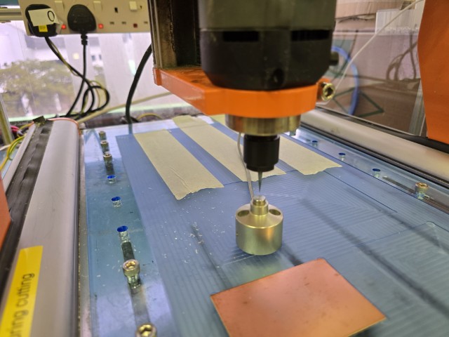
This is important as we are milling in millimeters, any error in the leveling of the Axis Z can make the paths either too deep or too superficial.
5. Open the G-Code file to be milled with the button LOAD FILE, we start first with the “Paths”. We locate X and Y positions where we want the starting point to be on the job.
6. Then we write at the MDI the X, Y coordinates and 25.0 height for Z.
Push CYCLE START to start the milling process. We started at 100% speed (The speed at which the tool moves through the material).
Characterization Tests
For our characterization tests, we will use the following Fab Academy template and with a V-bit engraver, mill it out with two different tool settings in Mods (0.3mm and 0.4mm cut depth) and then observe the results.
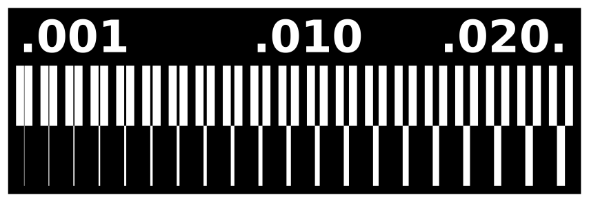
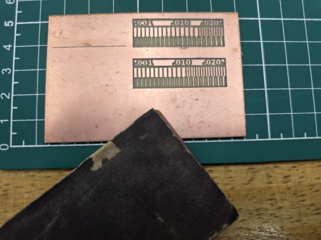
Here is a photo of our finished test mills. We did not need to sand/deburr as we used a need engraver for this job and the result is very clean.
Results
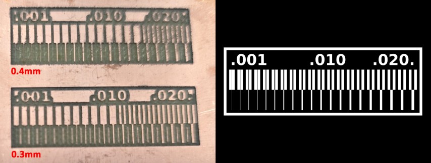
Looking at our results (upper rows), we observed that for the 0.4mm setting, the gap channel on the only starts to show at 0.016mm. This means that with this setting, details of width less than 0.016mm will not show up.
By using a 0.3mm setting, the gap channel on the upper set only starts to show at 0.013mm, which is finer than the 0.4mm setting. This means that with this setting, details of width less than 0.013mm will not show up. It also means that you can achieve mill out gap channels of smaller width by adjusting the depth settings to a lower value.
Comparing the lower rows with the template, we can see that we that at the 0.4mm setting, it more accurately reflects the template. Using a 0.3mm setting leaves tiny strips of material in-between.
Workflow for sending a PCB to a boardhouse
We asked ChatGPT the following question:
Explain the process of sending a PCB design to a boardhouse for production.
For this section, we will document our experience of sending a PCB design to the board house, and compare them with the steps recommended by ChatGPT below:
1. Design the PCB
• Use PCB design software like KiCad, Eagle, Altium Designer, or EasyEDA to create the schematic and PCB layout.
• Define board parameters such as layer count, board size, trace width, via types, and copper thickness.
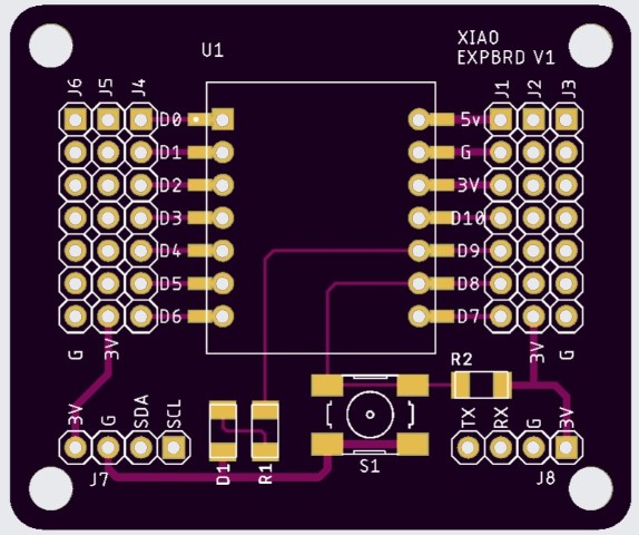
Our experience – We used a board designed by our instructor, Steven in Eagle.
2. Run Design Rule Check (DRC) & Electrical Rule Check (ERC)
• Ensure that traces have proper clearance, vias are correctly sized, and there are no overlapping elements.
• Verify net connectivity and confirm that there are no unintentional shorts or open connections.
Our experience – These checks have already been completed during the board’s design phase.
3. Generate Gerber Files & Other Manufacturing Files
• Most PCB manufacturers require Gerber files, which are standardized files that contain the board’s layer information.
• Required files typically include:
o Gerber Files (for copper layers, silkscreen, solder mask, and drill holes)
o NC Drill File (for hole locations and sizes) o Bill of Materials (BOM) (if ordering assembly)
o Pick and Place (Centroid) File (for automated assembly placement)
• Some manufacturers accept other formats like ODB++ or IPC-2581, but Gerber is the most common.
Our experience – We exported Gerber files through the process described below.
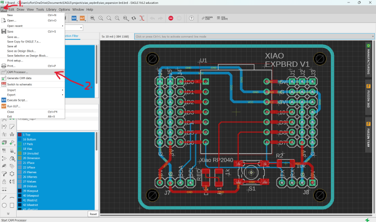
Click on File --> Cam Processor
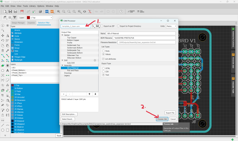
Since the board design is 2 layers, select a -layer board template. Then click Process Job to generate the Gerber files.
4. Select a PCB Manufacturer (Boardhouse)
• Choose a manufacturer based on:
o Lead time
o Pricing
o Minimum trace width and spacing
o Layer count and material options
o Special requirements (flex PCBs, high-frequency materials, etc.)
• Examples of PCB manufacturers include JLCPCB, PCBWay, OSH Park, Seeed Studio, and Advanced Circuits.
Our experience – We used JLCPCB.
5. Upload Design Files & Configure Order
• Most manufacturers have an online portal where you upload your Gerber files.
• Specify key parameters such as:
o Material (e.g., FR4, Rogers, Aluminum)
o Board Thickness (e.g., 1.6mm, 1.2mm) o Copper Weight (e.g., 1oz, 2oz) o Surface Finish (e.g., HASL, ENIG, OSP)
o Solder Mask & Silkscreen Color
• Choose quantity and lead time.
Our experience - We configured our order settings as shown below.
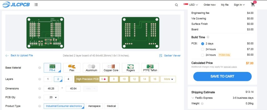
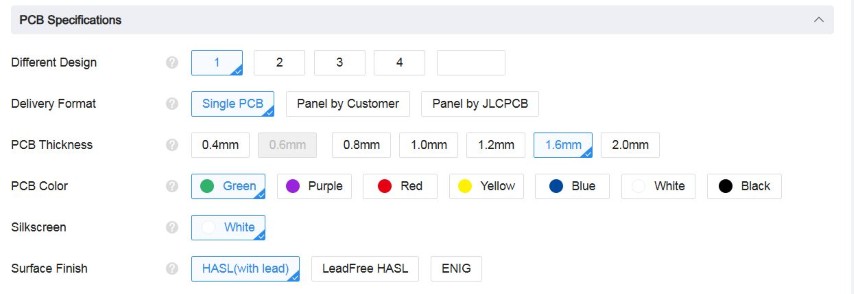
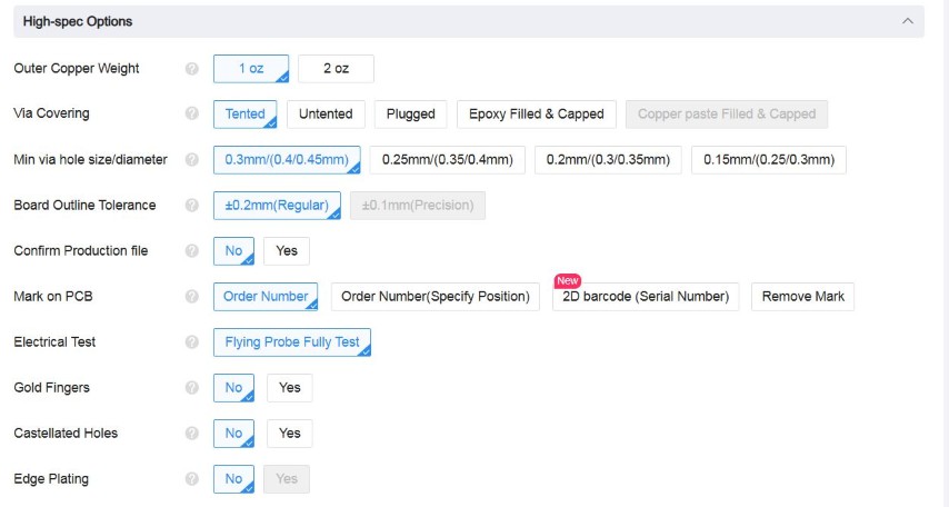
We did not go beyond this step as we were only going to order and pay for the board later. For this assignment, we stopped at this step. The steps after this are documented just for sharing.
6. Review & Approve the Manufacturer's Design Check
• The manufacturer may provide a DFM (Design for Manufacturing) check and flag any potential issues.
• Review their report and approve or make modifications if needed.
7. Place the Order & Make Payment
• Once you finalize the details, confirm the order and make payment.
• Some manufacturers offer expedited production and shipping options.
8. PCB Fabrication & Quality Control
• The boardhouse will:
1. Print the design onto copper-clad laminate.
2. Etch unwanted copper away.
3. Drill holes and vias.
4. Apply solder mask & silkscreen.
5. Surface finish application (e.g., HASL, ENIG).
6. Perform electrical testing to check for shorts/opens.
9. Shipping & Receiving the PCB
• Once fabricated, the PCBs are packed and shipped.
• Upon arrival, inspect the boards for physical defects or missing features before assembly.
Conclusion
This week we learnt how to use the desktop CNC to mill PCB boards, and also how to prepare the files and send them to a boardhouse to manufacture.
By learning to do both, we have the option in future to either make our own PCBs or send them to a boardhouse to get them manufactured. For example, if we just need 1 or 2 boards to use for a project, we can make it ourselves. However, if we need to produce a large quantity, we can use the services of a boardhouse. This concludes our Group Assignment for this week.
Design Files
