10 - Output Devices
Outputs are one of the fundamental elements of any system. This week, a CNC shield will be designed to drive different stepper motors.
INTRODUCTION
In automated systems, circuits are typically divided into two main stages: control stages and power stages.
Control stages are responsible for the logic and management of the system (Microcontrollers, etc.). They include components that process signals and make decisions
based on inputs and predefined conditions like.
Power stages are responsible for supplying the necessary energy to operate the actuators and motors of the system. They include components
that handle high currents and voltages. Common elements in power stages are:
- Power supplies: Provide the electrical energy needed for the system's operation.
- Transistors and relays: Act as switches to control the flow of current to the actuators.
- Motors and actuators: Generate movement or perform physical actions in the system.
- Power converters: Transform electrical energy from one form to another, such as from AC to DC.
Motors, for their part, are essential in automated systems because they are responsible for generating movement and performing specific tasks. Although there are many types of motors, they can generally be classified into four main categories:
- Servomotors. Used for applications requiring high precision and exact control
- DC Motors. Known for their simplicity and good speed control.
- AC Motors. Durable and requiring low maintenance.
- Stepper Motors. Provide precise position control.
| Motor Type | Advantages | Disadvantages | Applications | Characteristics |
|---|---|---|---|---|
| Servomotors |
|
|
|
|
| DC Motors |
|
|
|
|
| AC Motors |
|
|
|
|
| Stepper Motors |
|
|
|
|
shield design
A CNC shield is planned to drive various stepper motors, so a microstepping driver is required. The A4988 will be used, and the datasheet is presented below:
The first thing we need to do is calculate the width of our tracks, so we need to know the maximum current the driver can handle. In the A4988 datasheet, we find that the maximum current is \(2A\) per microstepping driver. Using the KiCad calculator, we get an approximate track width of \(0.8mm\).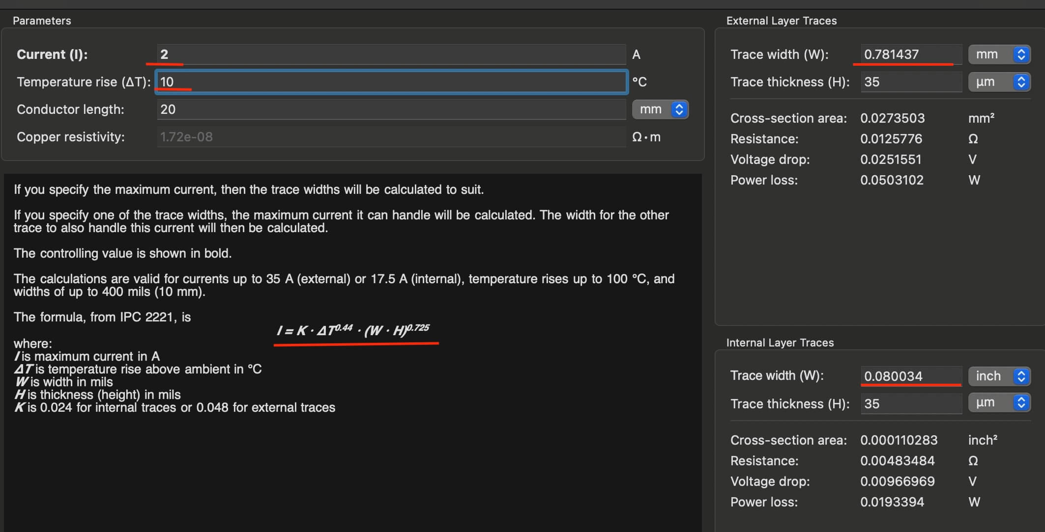
Based on the "A4988" data sheet, the following schematic is obtained.
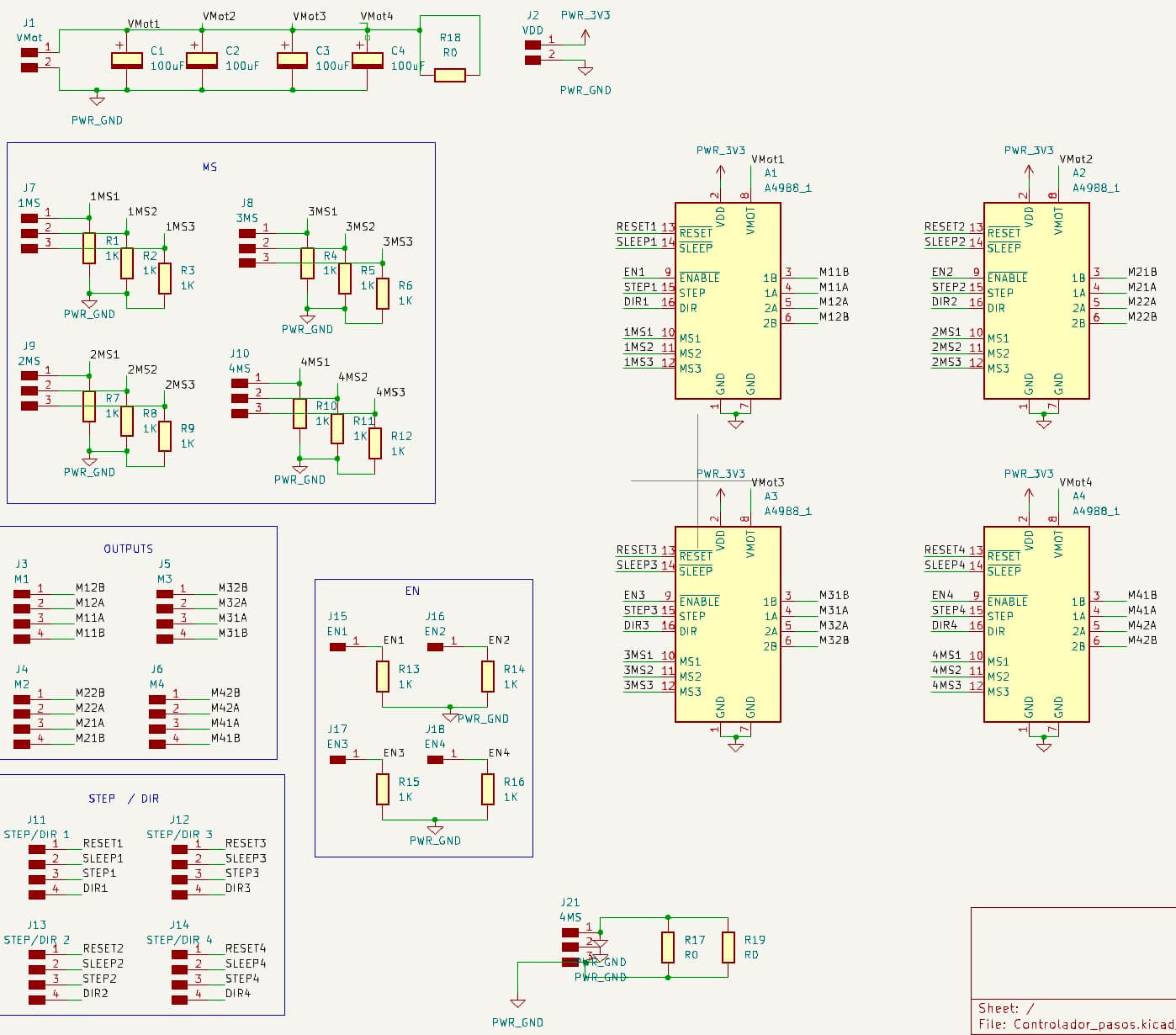
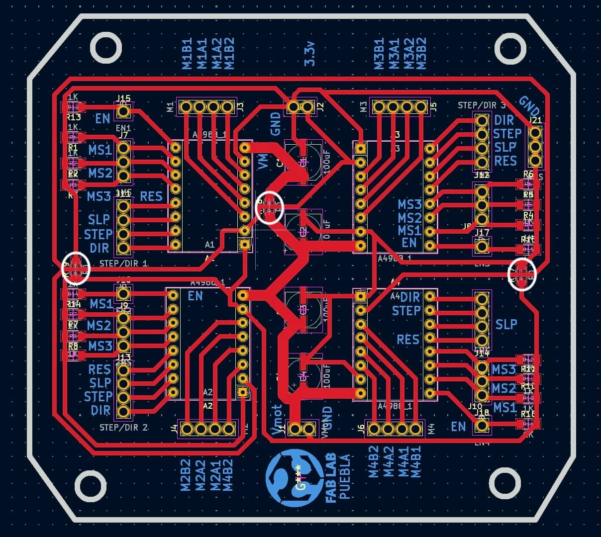
Once the schematic shows no problems with the "ERC", we move on to the "PCB Editor". The image below shows the finished design. It is important to
note that "\(0 \Omega\)" resistors (white circles) were placed, as these will act as bridges to connect different tracks.
Not all stepper motors are expected to operate at the same time or draw maximum current, so you can see in the drawing that the external
power supply has a larger width (\(2 mm\)) to support any current requirements that may arise.
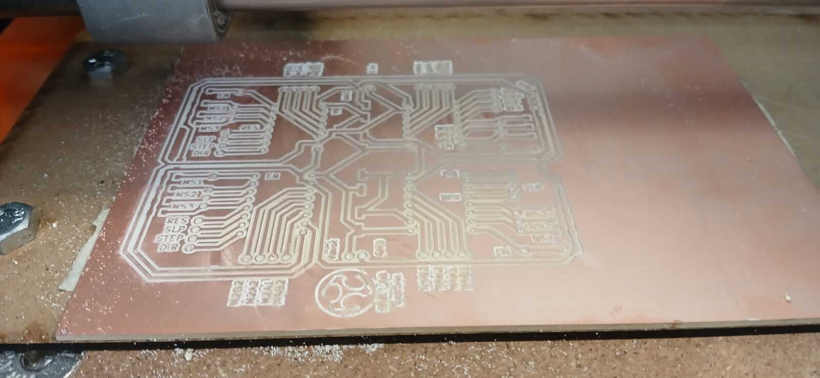
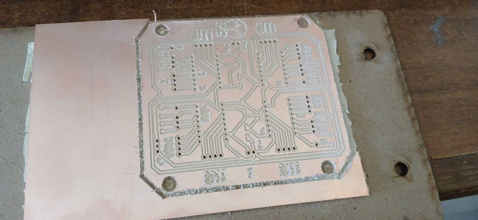
The images below show the results of the machining.
Code
The following section shows the code created to move a stepper motor, reversing its rotation depending on the button being pressed. For
this purpose, we used the motherboard and keypad designed during the "
8.- Electronics Production ".
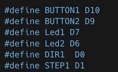
The first thing we do is define the pins that will be used.
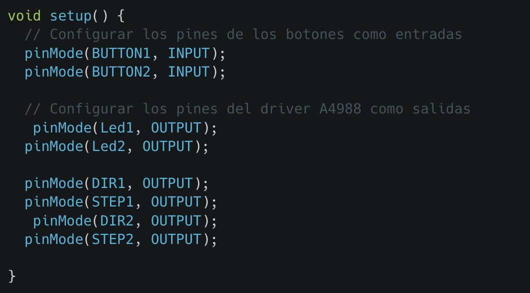
Once the pins have been declared, they are defined as inputs or outputs in the "void setup ()".
Starting the "void loop()" the conditions are declared by means of an "if", if the condition is correct a direction of rotation is assigned by means of the "Dir" pin, once the direction is declared a "for" cycle is entered to take a number of steps (800 in our case), within the "for" we change the logical level of the "Step" (high or low), so that the stepper motor can rotate, it is important to note that we have a delay in microseconds, which we can vary depending on the speed we want to have.
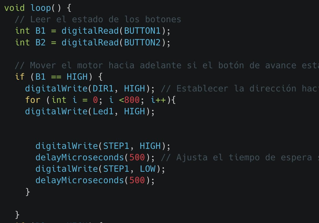
The complete code is shown below, and the file is at the bottom of the page.
soldering process
The following figures show the soldering process.


RESULT
The following image shows the board designed with all the "A4988 drivers".

The following video shows how the stepper motor rotates a certain number of steps, depending on which button is pressed.
Learning outcome
It is essential to separate the power from the control stage to avoid interference and ensure optimal system performance. Unifying the grounds
is also crucial to maintaining signal integrity and avoiding noise problems.
Furthermore, considering the current that the output elements will draw is essential for properly sizing components and ensuring the safety
and efficiency of the design.
