9 - Input Devices
This week we will learn the importance of the input signals received by devices, focusing mainly on sensors and how they interact with the environment to provide information (in our case) to the microcontroller.
INTRODUCTION
Sensors are devices that detect and respond to physical or chemical stimuli from the environment. These stimuli can include light,
temperature, motion, pressure, humidity, sound, among others. Sensors convert these stimuli into electrical signals that can be
processed and analyzed.
The most common types of sensors are shown in the following links:
- Temperature Sensors : Measure the temperature of the environment.
- Motion Sensors : Detect movement and the presence of objects or people.
- Light Sensors : Measure light intensity.
- Pressure Sensors : Detect changes in pressure.
- Humidity Sensors : Measure humidity in the air or materials.
| Feature | Sensor | Transducer |
|---|---|---|
| Definition | A device that detects and measures physical properties from the environment | A device that converts one form of energy into another |
| Function | Measures physical quantities and converts them into readable signals | Converts physical quantities into electrical signals or vice versa |
| Output | Typically provides a readable signal (e.g., voltage, current) | Provides an electrical signal corresponding to the physical quantity |
| Power Source | May or may not require an external power source | Often requires an external power source |
| Examples |
|
|
| Feature | Active Transducers | Passive Transducers |
|---|---|---|
| How they work | Convert physical energy into electrical energy by generating their own voltage | Convert physical energy into electrical energy by modifying an external voltage |
| Power source | Do not require an external power source; generate their own electrical output | Require an external power source to operatey |
| Examples |
|
|
| Feature | Active Transducers | Passive Transducers |
|---|---|---|
| Applications |
|
|
| Pros |
|
|
| Cons |
|
|
Ultrasonic Sensor
When we ask to copilot "What is an ultrasonic sensor?", it gives us the following
information.
How Ultrasonic Sensors Work
- Transmission: The sensor emits ultrasonic sound waves using a transmitter.
- Reception: The sound waves travel through the air, hit an object, and reflect back to the sensor.
- Calculation: The sensor measures the time taken for the echo to return and calculates the distance using the formula:
\( D=\frac{1}{2}TC \)
where \(T\) is the time measured in seconds and \(C\) is the speed of sound (approximately \(343\) meters per second).
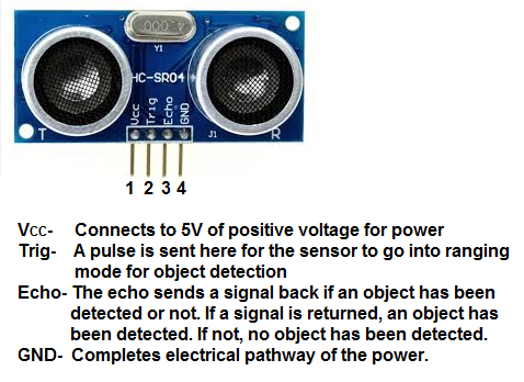
As you can see in the image, the sensor needs a 5V power supply, so an external source will be necessary to connect it to the "XIAO RP2040", the problem is that the signal coming from the "Echo" can damage the controller, so it is necessary to place a resistor and protect the device, so through a voltage divider, we have to make the resistor drop a voltage of \(1.8v\). According to the data sheets, the maximum current supported by the input pins of the "XIAO RP2040" is \(4mA\). Based on that we can make the following calculations:
In the case of "Trig," it is connected to a controller output pin, which is used to trigger ultrasonic pulses. Setting this pin to HIGH for \(10 µs\) triggers the sensor to initiate an ultrasonic burst. An animation ( MCI educación ) of the sensor's operation is shown below.

- HCSR04 Datasheet
- HC-SR04 Ultrasonic Sensor
- Guide for Ultrasonic Sensor HC-SR04 with Arduino
- ¿Cómo funciona el sensor ultrasónico HC-SR04 y cómo se conecta con Arduino?
NEW TEST BOARD
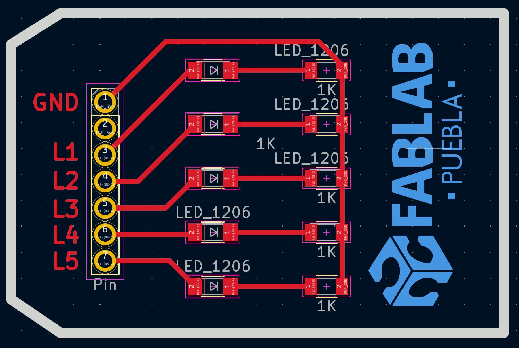
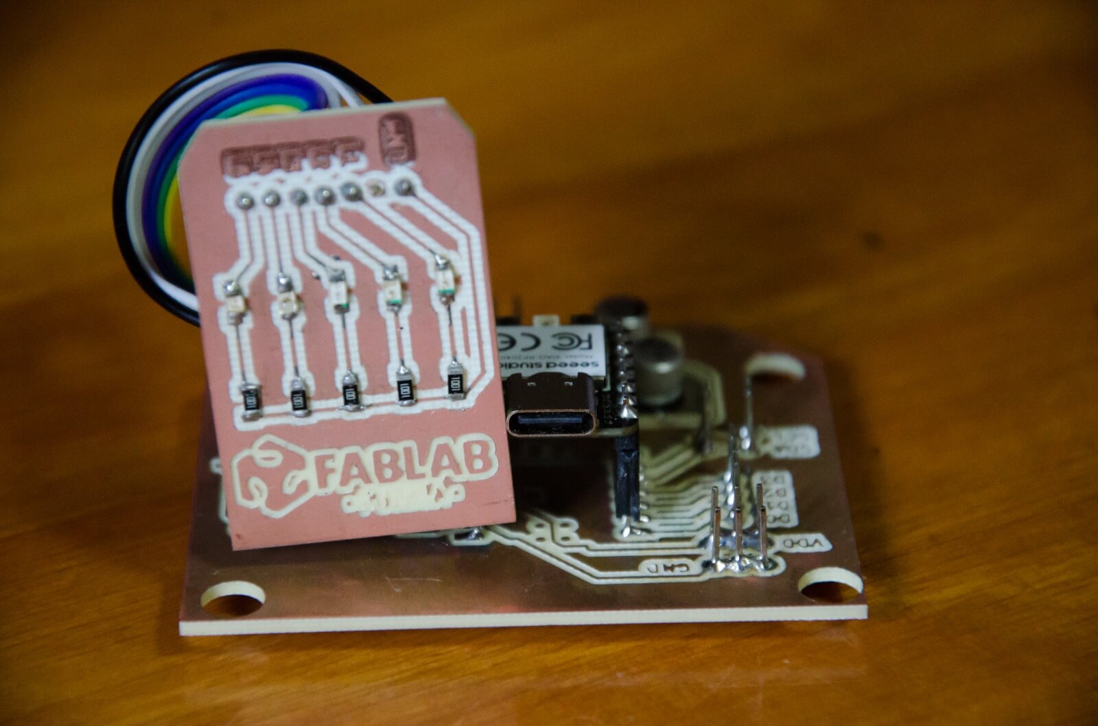
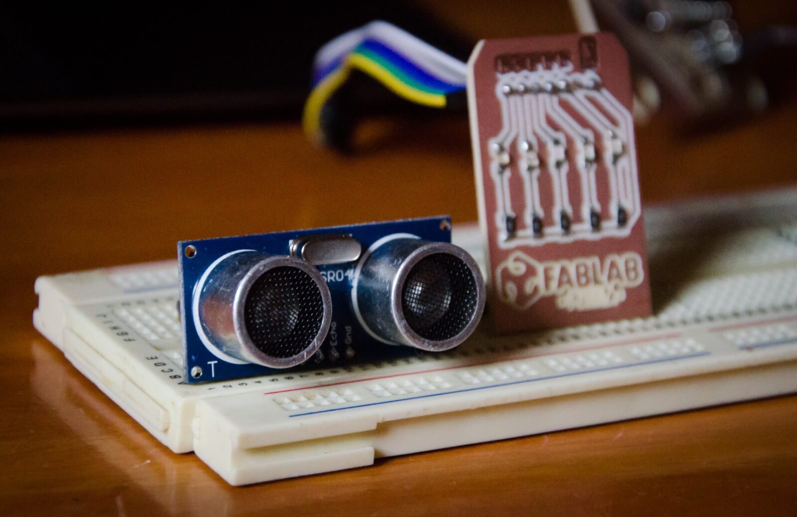
The idea is that depending on the distance between an object and the sensor, several LEDs will light up as the thermometer form. To do this,
it's necessary to design a new test board, which will be connected to our main board made during the
"Electronics Production" week.
The test board will consist of 5 LEDs of different colors and 1kΩ resistors that will be connected to each LED respectively.
Code
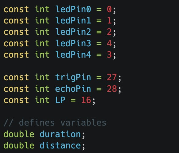
The goal is to be able to visualize a strip of LEDs as an object approaches or moves away, so the first thing to do is declare all the variables, which include the output LEDs and the "Trigger" and "Echo".
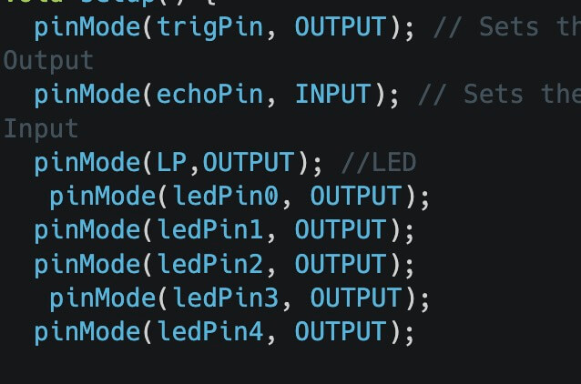
The next step is to define the pins as inputs and outputs using the "pinMode" instruction within the "void setup()".
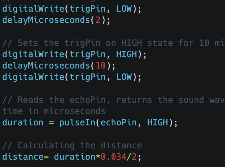
In the "void loop()" we start by turning the trigger on and off with a pulse width of \(10 μs\). Then, using the formulas mentioned in the data sheets, we calculate the duration (time in which the sound returns) and the distance.
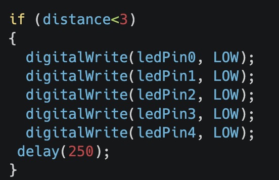
The last step is to set the conditions for turning the LEDs on and off depending on the distance.
The complete code is shown below, and the file is at the bottom of the page.
RESULT
The following images show the "Ultrasonic Sensor HC-SR04" with the LED board.
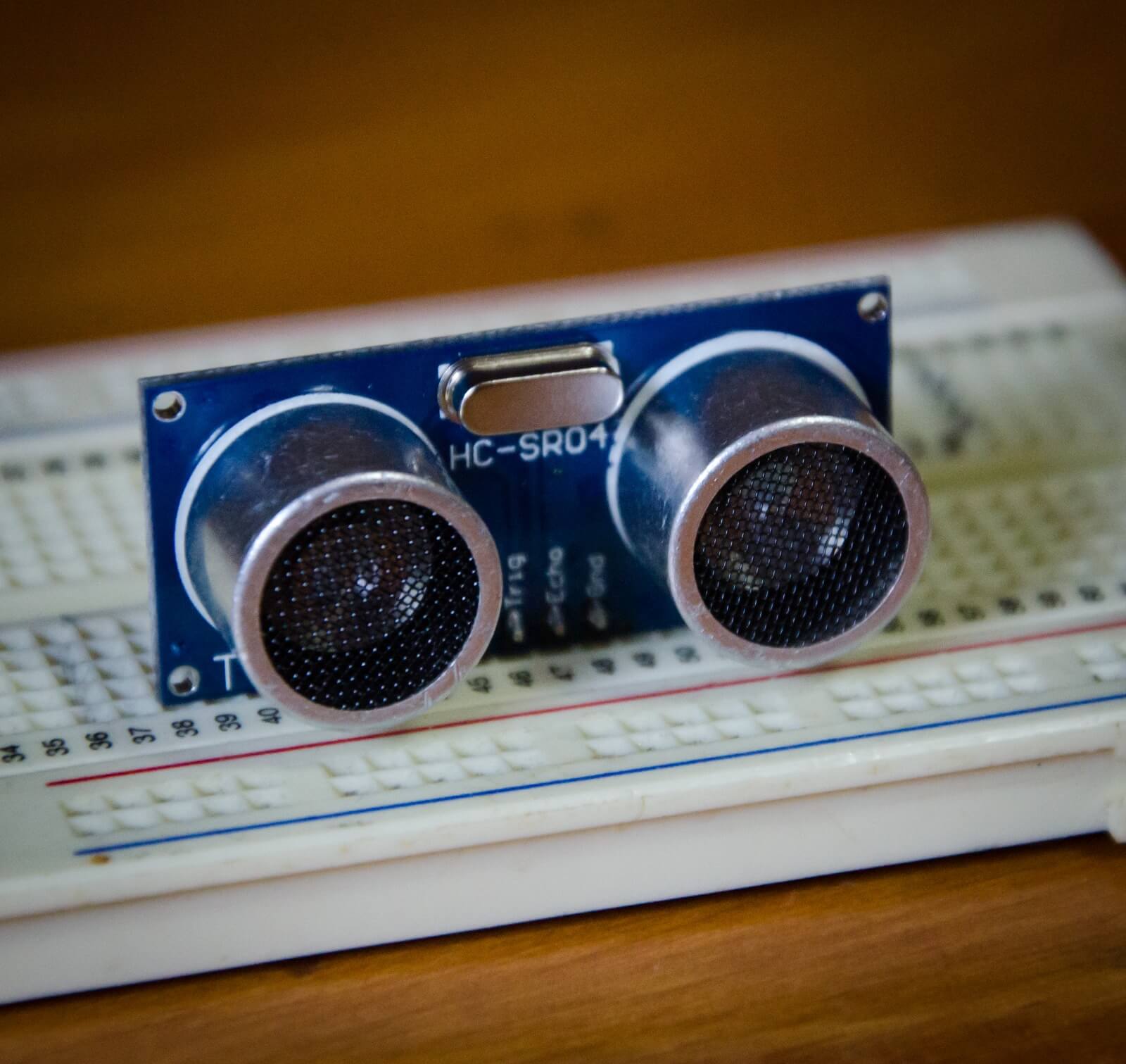
Video of how it works when moving an object closer or further away from the sensor
Learning outcome
This week we learned about the importance of input elements such as sensors. It's important to understand how a sensor works before using it, since "we can't program something we don't understand."
