8 - Electronics Production
The following section demonstrates the PCB manufacturing process, starting with the Mods CE workflow, continuing with the use of "PCB Milling ", and ending with the soldering process.
We'll use the assignment to focus on moving forward with the final project.
MY FIRST STEPS IN "MODS CE"
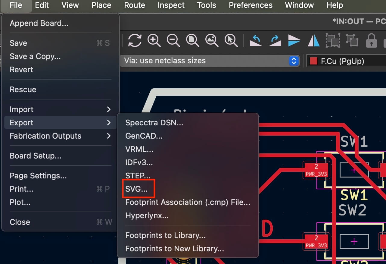
The first thing to do is generate an SVG file. To do this, we use the designs created during week "6.- Electronics design" . We open KiCad in the "PCB Editor" and follow the path: "File - Export - SVG..."
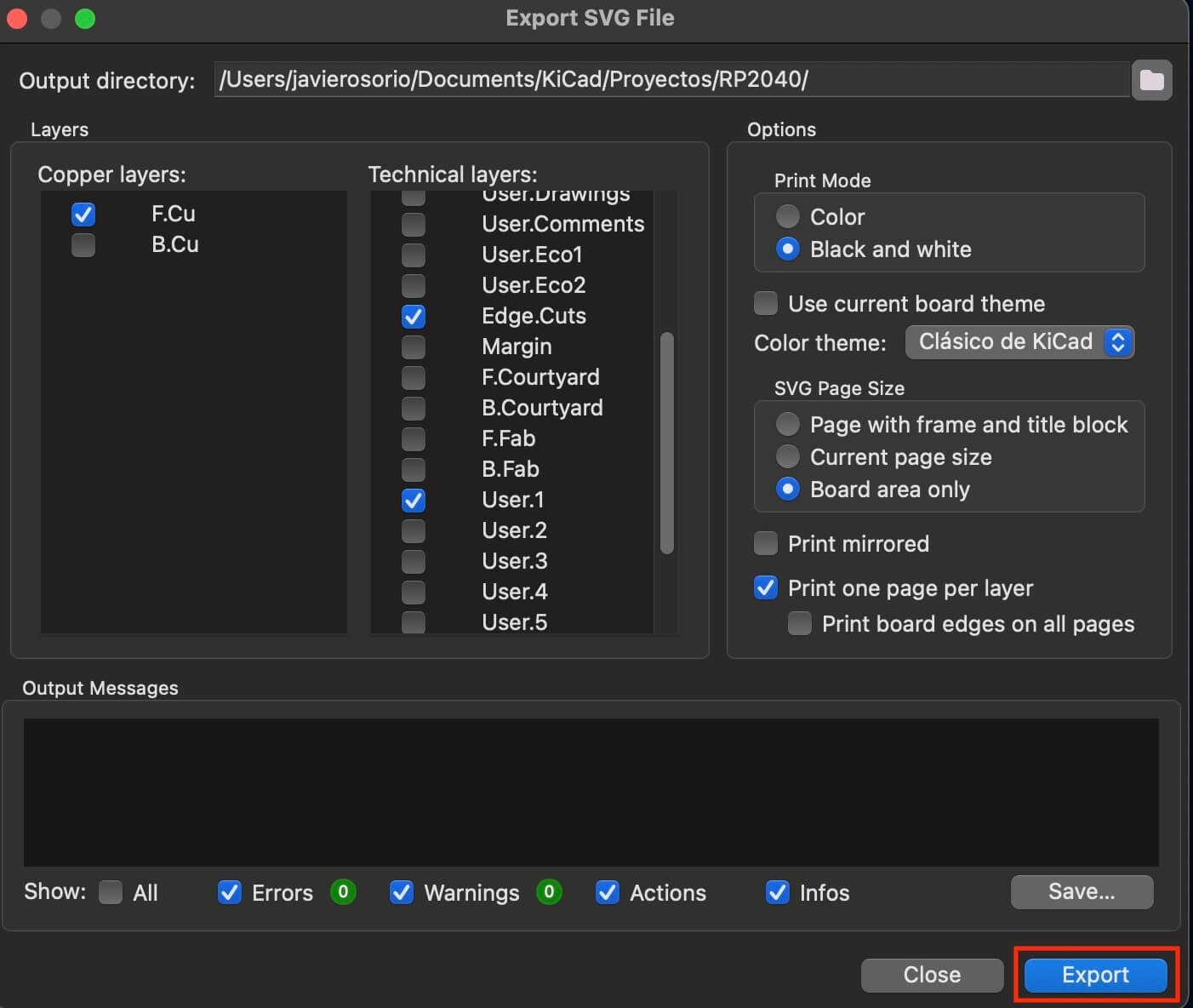
Doing this will open a new window where we must select all the layers used. It's important to select "Black and white" in Print Mode and press "Export."
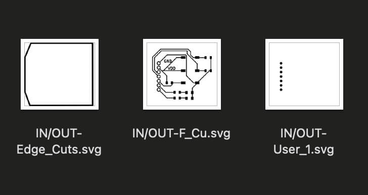
Pressing "Export" generates different files corresponding to each layer selected in the previous step, where they will be saved in the address specified in the previous step.
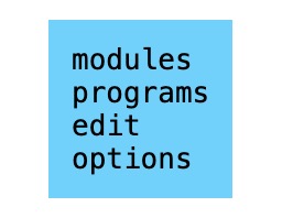
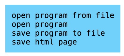
The next step will be to open Mods CE, in any section of the window we will right click, when doing this a new window will open where we must select "programs" to open another new window and select "open program".
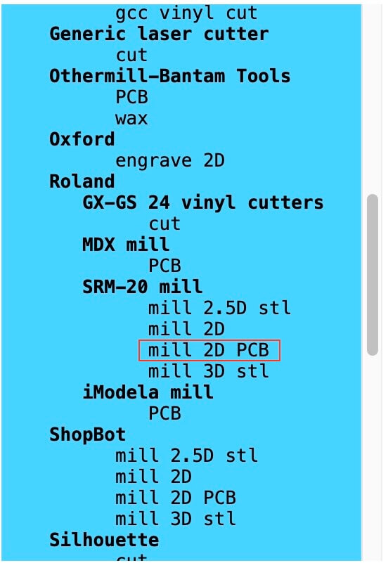
A new window opens and shows us all the CNC machines you can work with. In our case, we're working with the "SRM-20 mill" and selecting "mill 2D PCB".
This opens a new window, presenting the entire workflow. The image below shows the order we should follow.
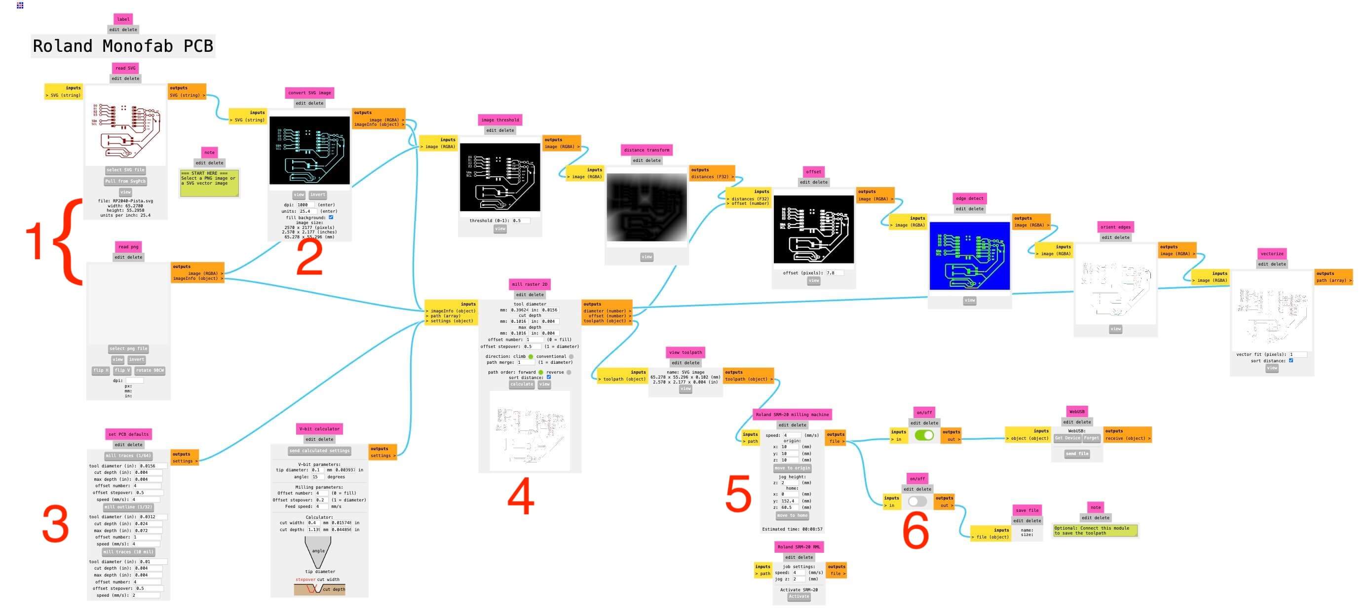
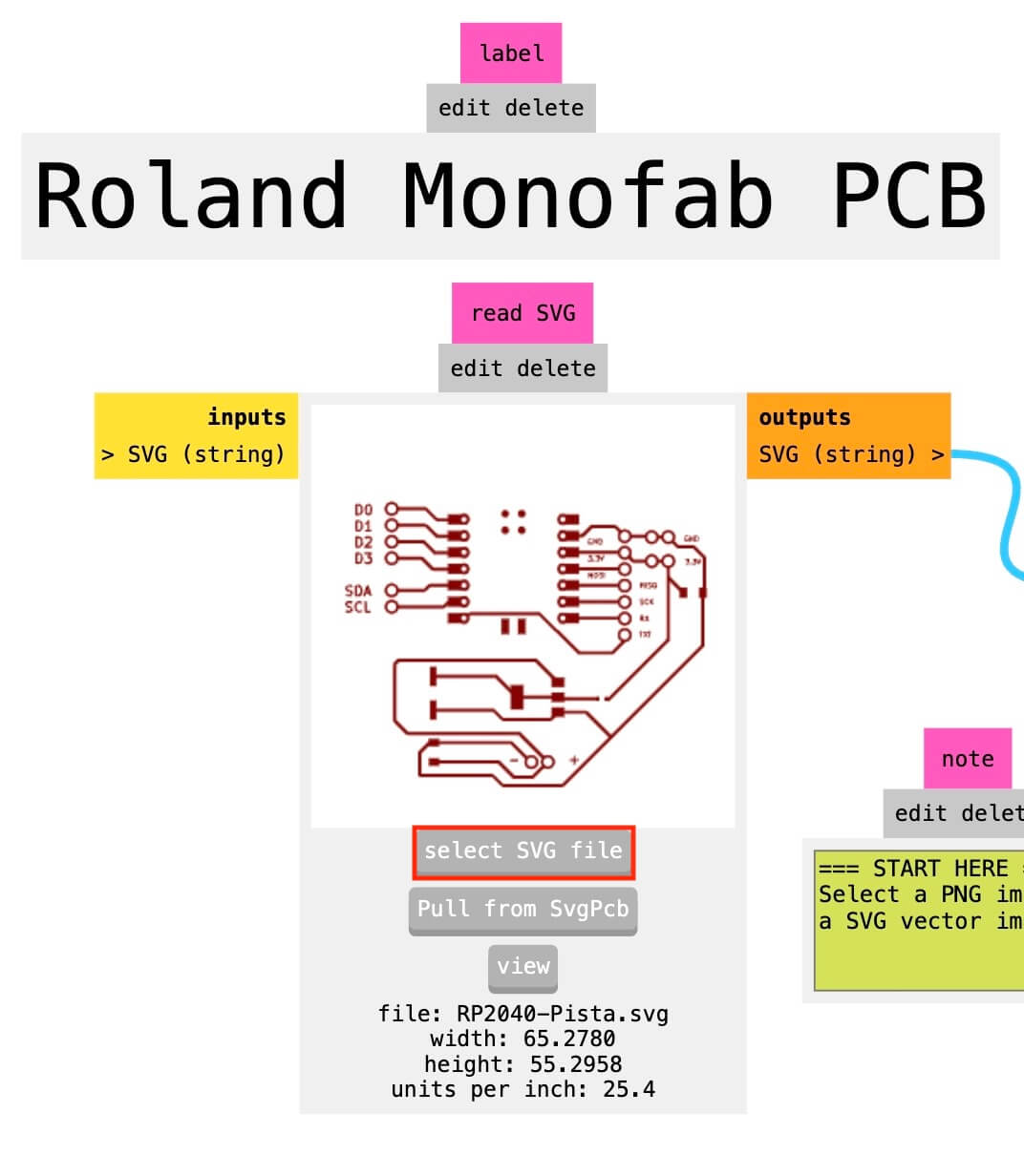
The first thing to do (Step 1) is to load the file we want to work with (SVG or PNG), with this we will have the visualization of the loaded file.
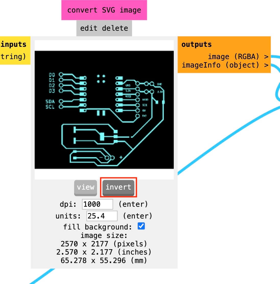
Step 2. It's important to note that the cutter only cuts the black color shown in the pictures, so if you want to create the outline of the tracks, it's important to invert the layer so the cutter doesn't go over the tracks. If it's a border, the black lines should be the traces (strokes), as they are the elements you want to cut. The image below shows how the tracks should look.
Step 3. Once the file is loaded, it is important to know whether we want to make a layout or a cut. If we want to make a track layout, we press "mill traces" If we want to drill or cut the edges of the plate, we select "mill outline."
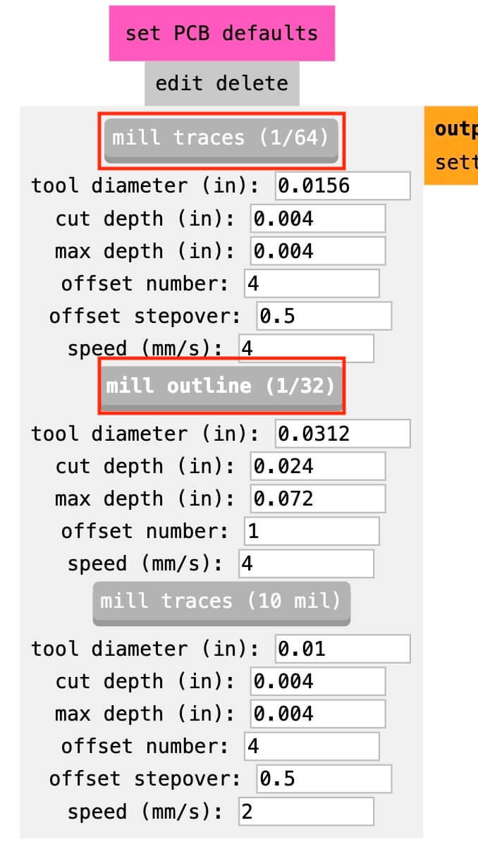
Step 4. It's important to note that the tool diameter and depth of cut vary depending on the selection. The picture on the left shows the mill traces configuration, and the figure on the right shows the mill outline. An important point is the offset number, where the number corresponds to the number of passes the tool will make to remove material. The more passes, the less copper material will be left on the plate, with "0" being the maximum number of passes (the plate will only be left with the traces). The more passes, the longer the machining time.
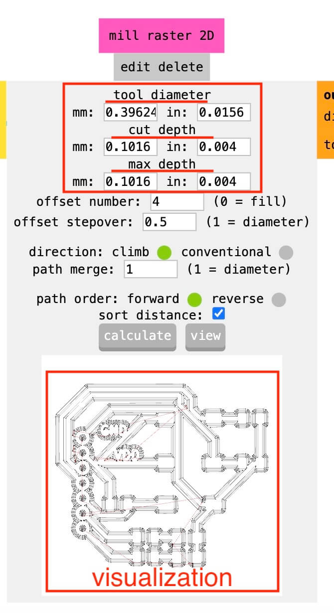
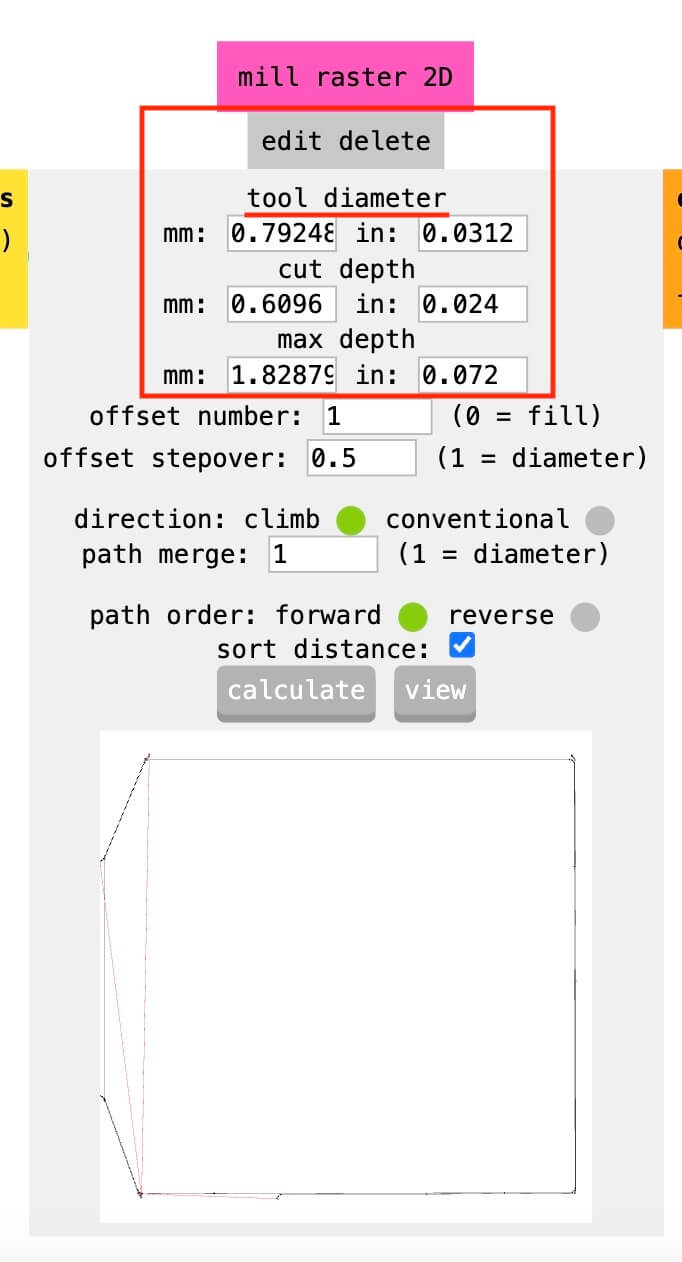
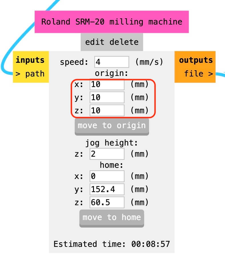
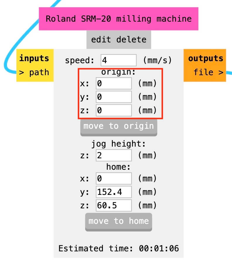
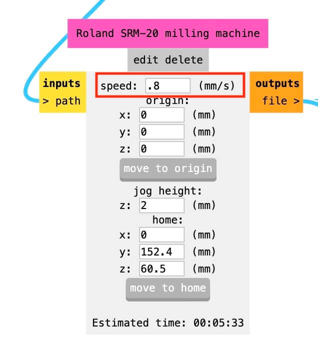
Step 5. By default, the program sets an origin; it's important to set all these values to "0." Below this section, the estimated processing time appears. The images show a time difference, which is due to the offset number.
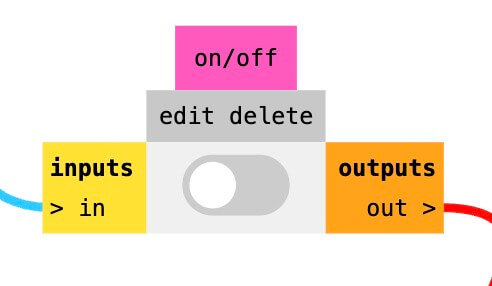
Step 6. The last step is to save the file. To do this, move the "inputs" button to "outputs" and press "calculate" again (see image in step 4). This will automatically download the file with the " .rml " extension.
- Through hole
- Tracks
- Edge cutting
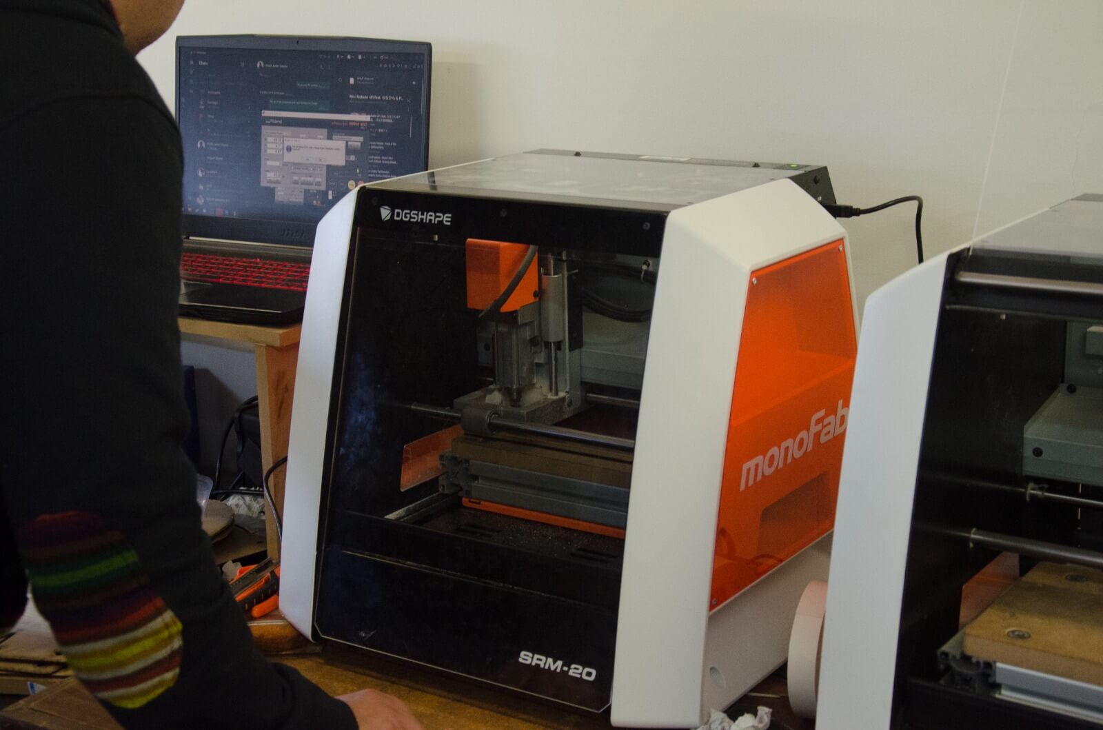
Mini Mill - ROLAND SRM-20
We will be working with the ROLAND SRM-20, which is a next-generation desktop mill that boasts a micro-step motor drive
system for clean and precise contours, G - Code compatible.
The following link shows the installation software as well as the manuals.
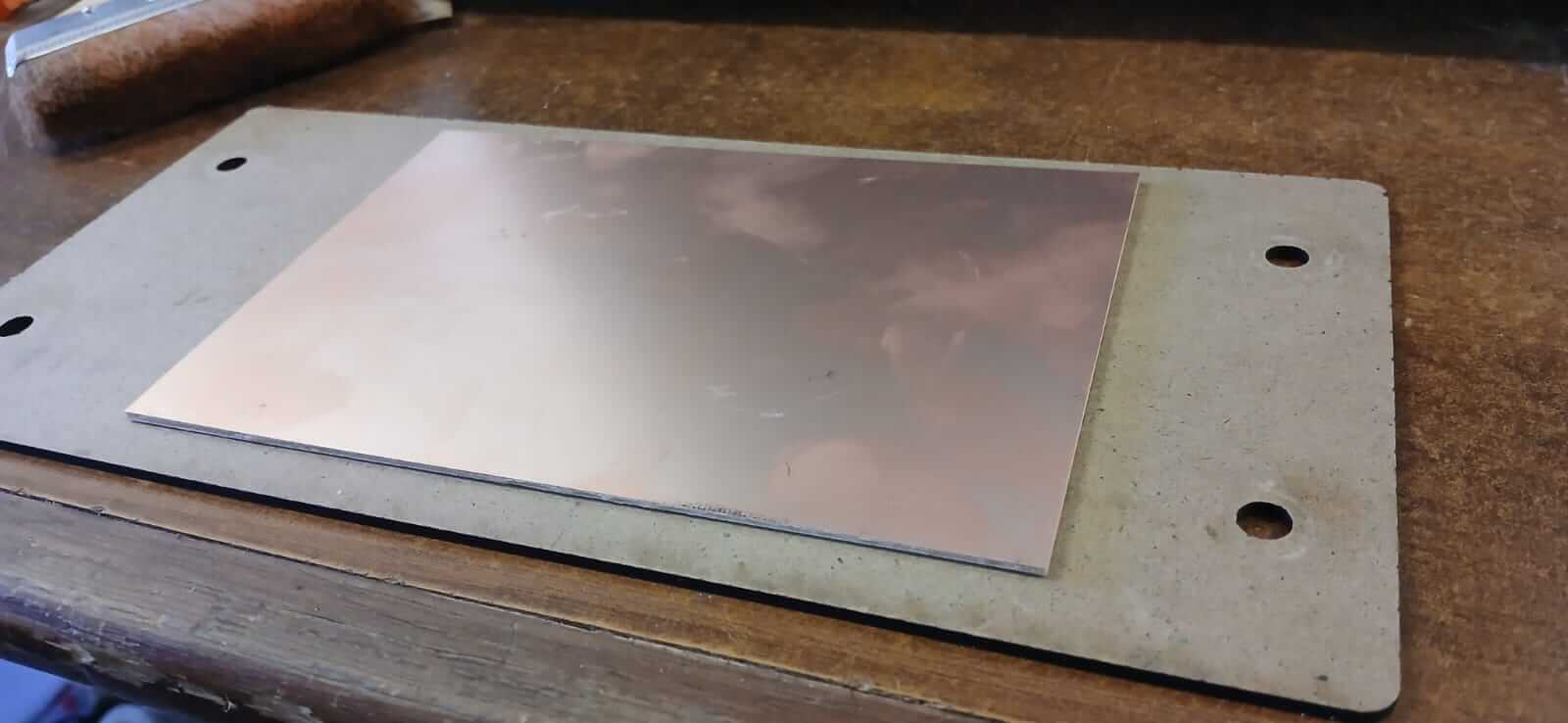
The first thing to do is to place the phenolic plate on the sacrificial bed using double-sided tape, ensuring that it covers the entire surface to avoid unevenness and prevent it from moving during the machining process.
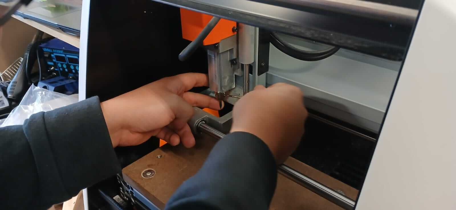
The cutting tool must be placed with the help of an Allen key, ensuring that it is snug so that it does not fall during the machining process.
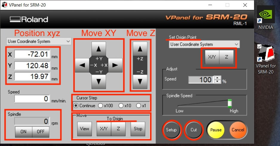
Once the cutting tool and the sacrificial bed are secured with the phenolic plate, proceed to close the lid (for safety reasons the CNC will not work if the lid is up). Open VPanel for SRM-20. The figure below shows how to move the "X", "Y" and "Z" axes, once the "XY" axes are placed in the right place, proceed to press "Set Origin Point XY", when doing this we will notice that in the "User Coordinate System" the values of "XY" appear at "0". To place "Z" it is important to turn on the "spindle" before starting to go down, it is advisable to control the descent speed by means of the "Cursor step", the closer we are to the phenolic plate the smaller the step should be, the last step is recommended to be "x1", since the aim is to touch the plate; Once the plate is touched, we place "Set Origin Point Z", when setting the value and seeing in "User Coordinate System" that all the values ("XYZ") are at "0", we must raise "Z" to avoid that when the machine starts to make the initial movement it breaks the tool.
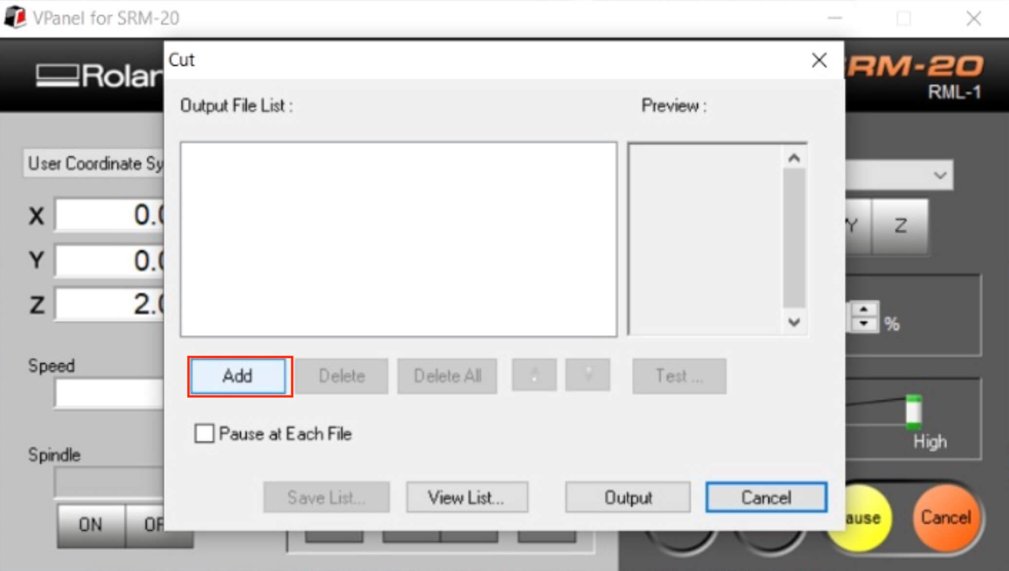
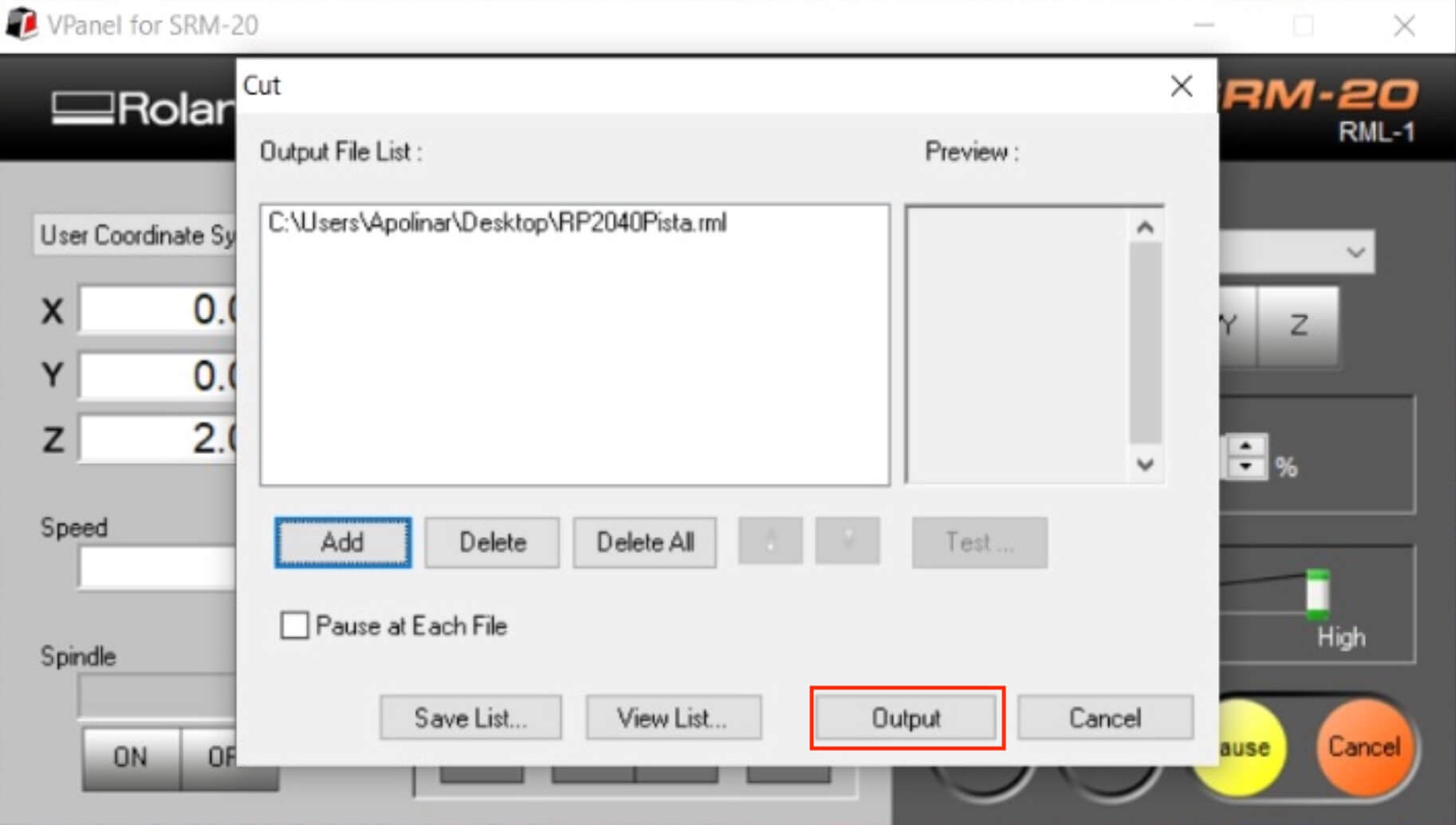
As a final step, we go to "Cut," which will open a new window. We select "Add" to load our document containing the cutting information (remembering to start with Through Hole, Tracks, and Edge Cutting). Once we have the desired document, we press "Output," and the CNC will begin working.
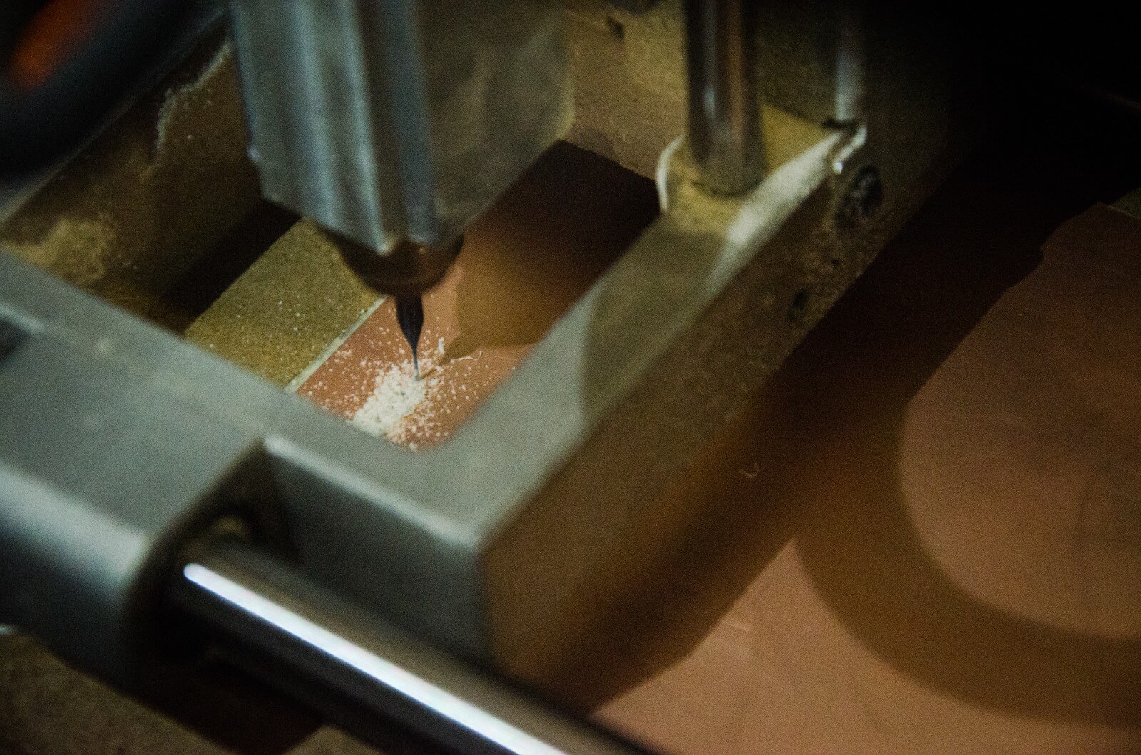
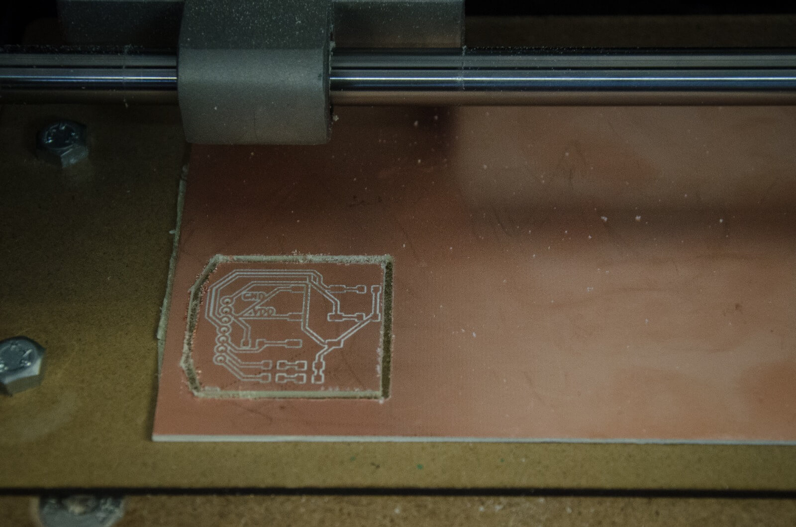
Below are some photos of the machining process.
MACHINING VIDEO
final result
SOLDERING STAGE
To start soldering it is important to have the following components:
- A soldering iron
- Solder wire
- Flux
- Tweezers
- How To Solder: A Beginner’s Guide
- Desoldering braid. Recommended for SMD joints or components.
- Solder sucker. Recommended for use when you have excess solder and large components. Its use is not recommended for SMD components as it can suck up the component and cause it to be lost.
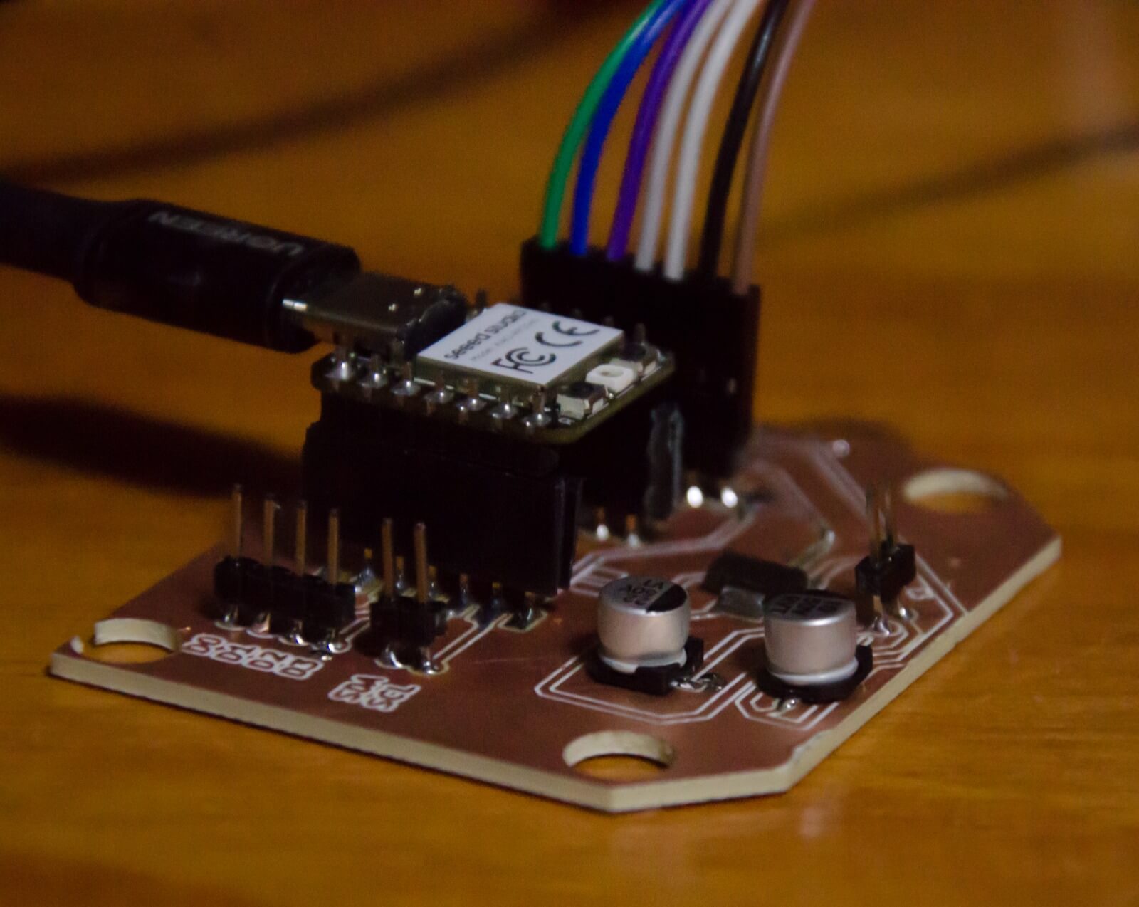
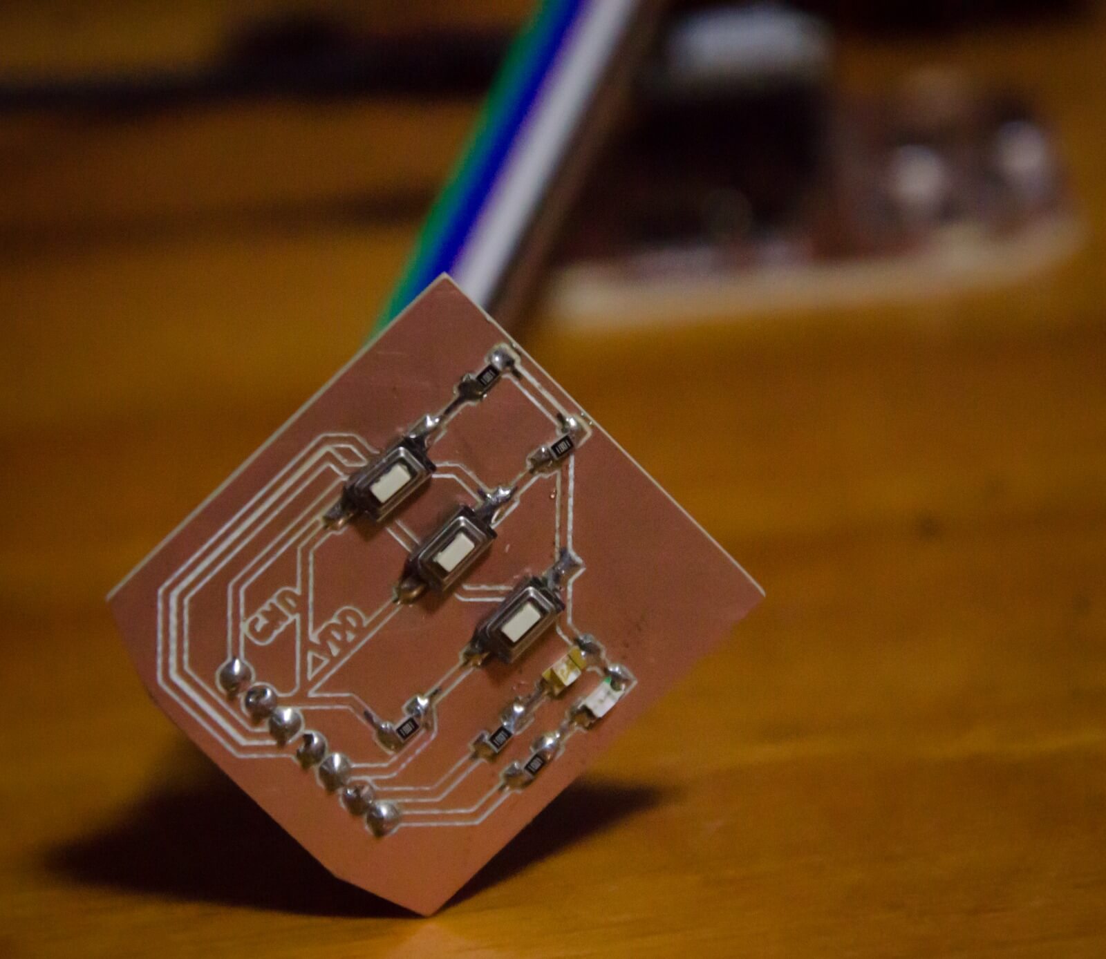
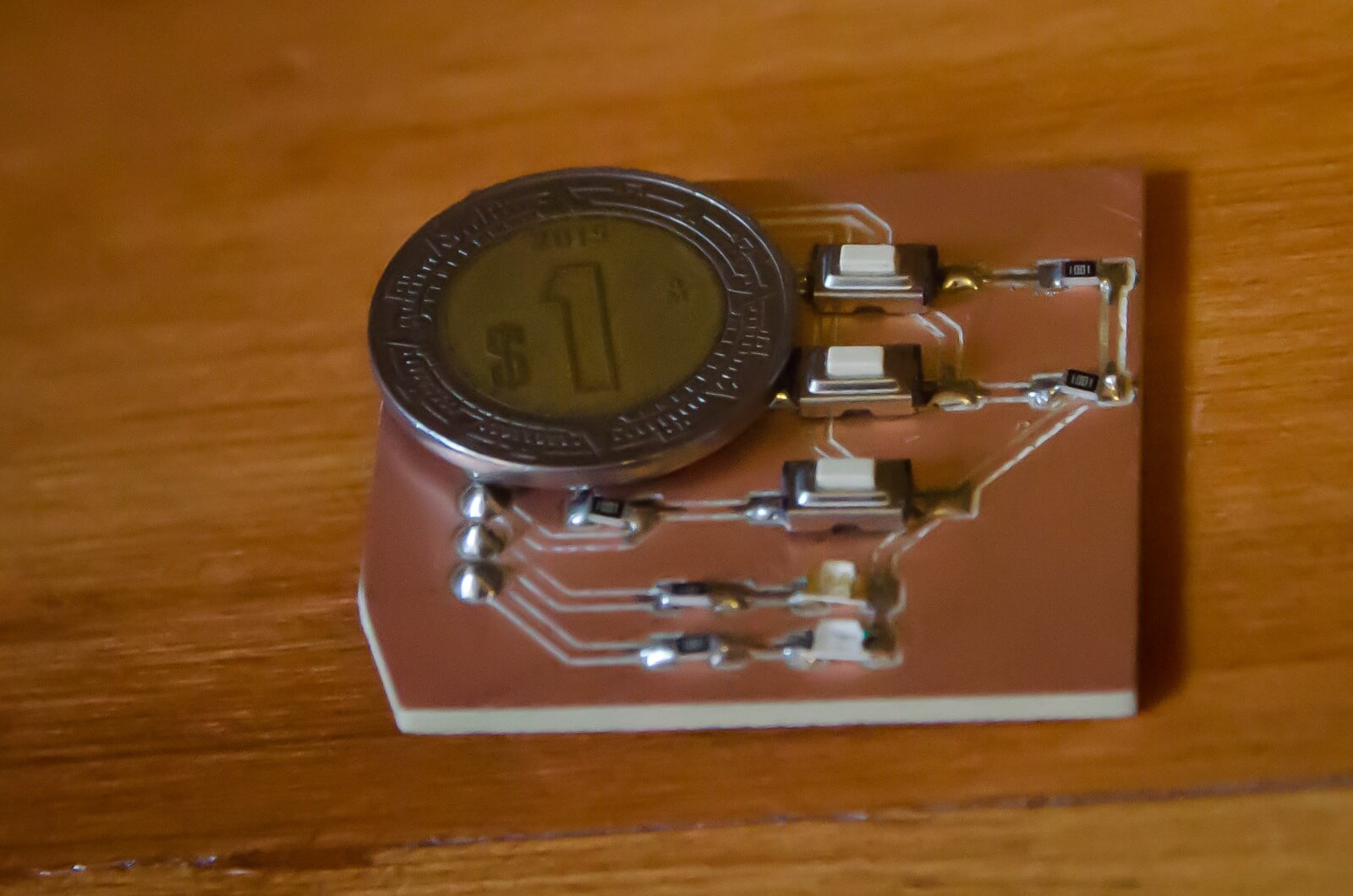
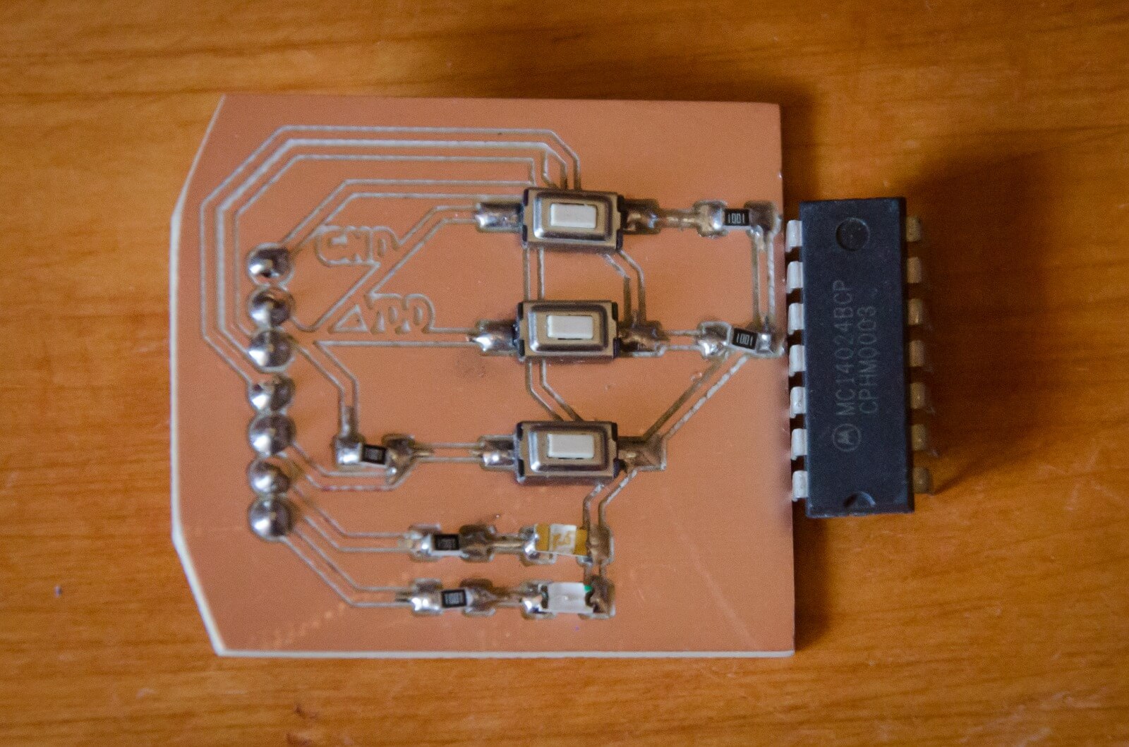
The following figures show the results of the soldering process.
TEST STAGE
Our test board consists of three pushbuttons, two in "Pull Down" configuration and the third in "Pull Up" configuration, and two LEDs (one orange and one blue). The first test consists of pressing one of the "Pull Down" buttons to latch the LED (leaves it on) and pressing the other to unlatch it (turns it off). The third button (Pull Up) toggles both LEDs on and off three times. The lines of code are shown below, as well as the physical test using our design.
The following test focuses on moving servomotors using the PCA9685 board and I2C communication. The objective is to rotate the servomotors by pressing the buttons on the test board (0°, 90°, and 180°). The implemented code and video of the servomotors are included below.
Learning outcome
This week, we learned how to use "Mods" to design "PCBs", as well as soldering techniques and processes. It's important to note that soldering of components “SMD” is a challenge, as it requires constant measurement with a multimeter to avoid short circuits on the board due to the small size of the components and the proximity of each other.
