7 - Computer controlled machining
This week we will make cuts using a CNC router from a drawing in .DXF format. It is necessary to have a specialized milling program, in our
case we will use the VCarve software.
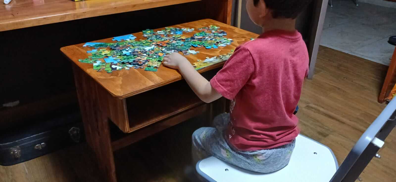
I will use the weekly task to build a desk for my son that allows the height to be adjusted as my son grows.
DESIGN
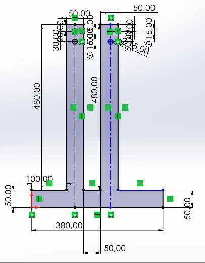
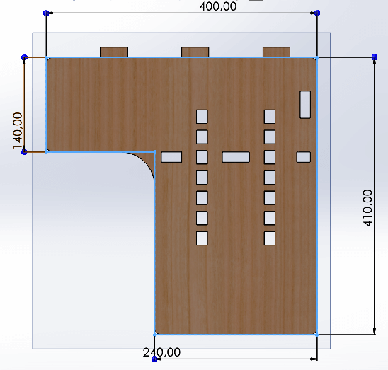
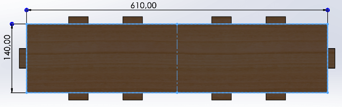
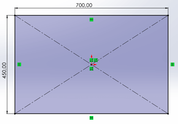
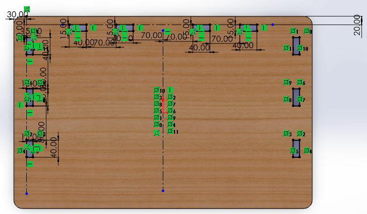
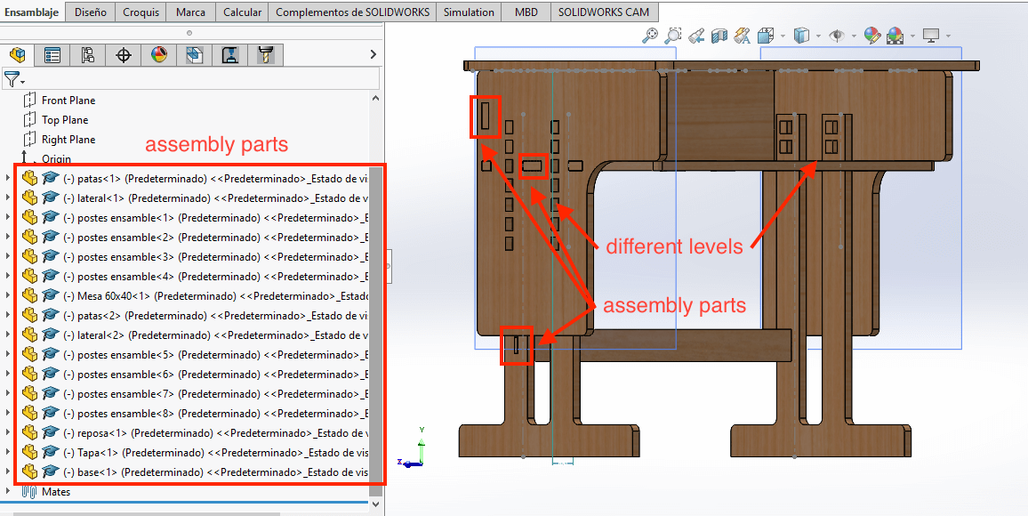
The first thing to do is to design the structure to be cut, for that we use "SolidWorks". The following images show each of the designed pieces as well as the assembly of each of them.
desk legs
sides of the desk
Cover
base below
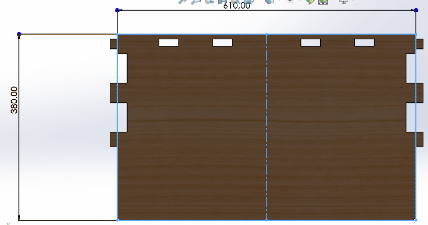
Table
assembly parts
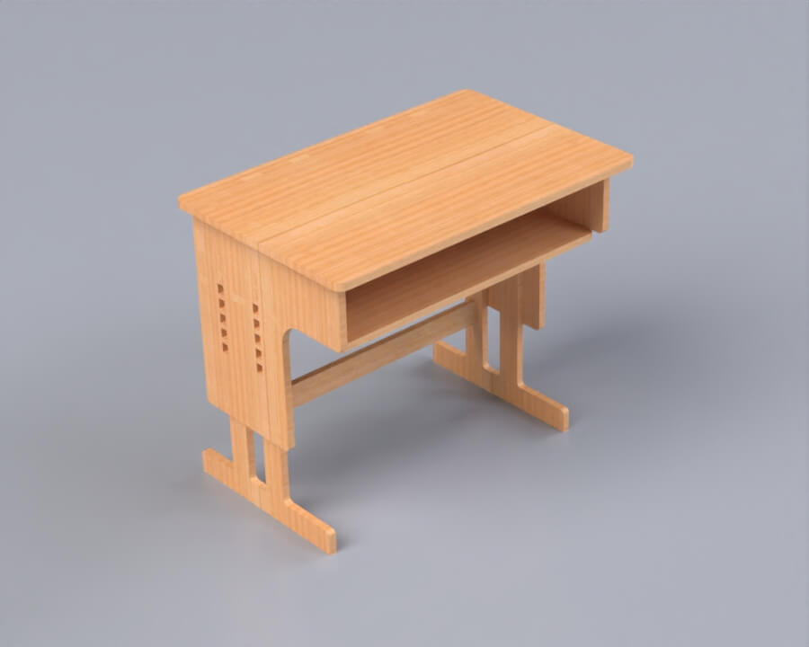
Render
VCarve
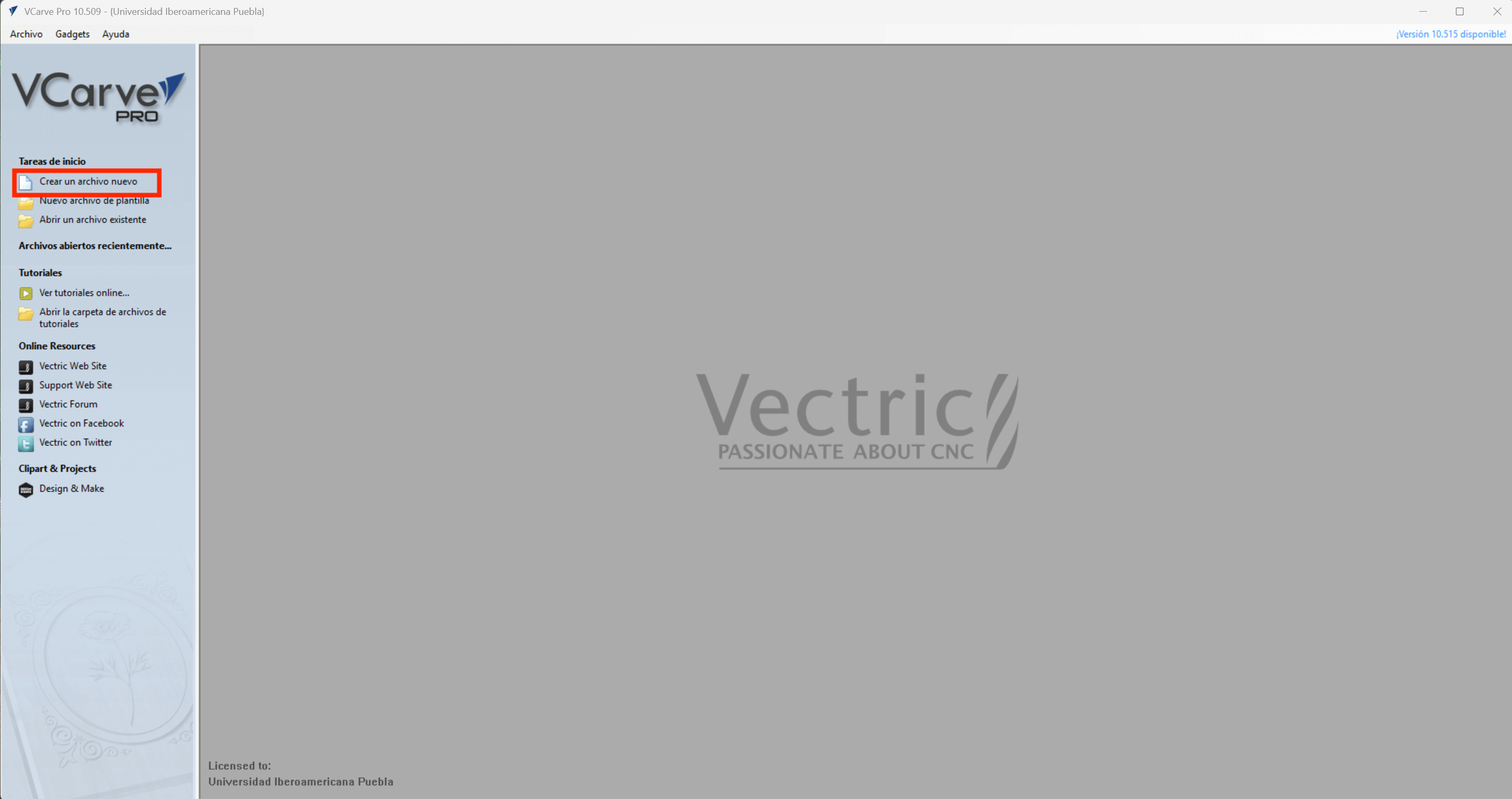
Once the designs have been created and the ".DXF" files are available, we proceed to open the VCarve software. On the main page we select to create a new file.
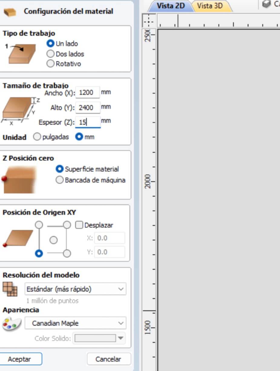
The above opens a new window on the left side, which is a material configuration window, inside it you must place the specifications of the element to be worked on such as width (1200mm), height (2400mm) and thickness (15mm), as well as the position of "z" and "xy". When you finish the configuration, click OK.
By doing the previous step, the menu on the left side changes, and is displayed as in the figure below.
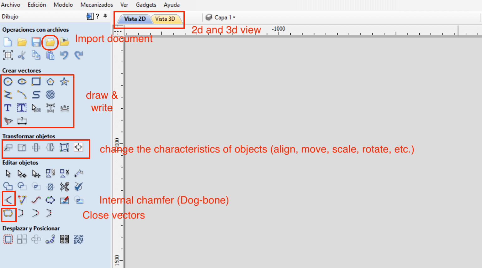
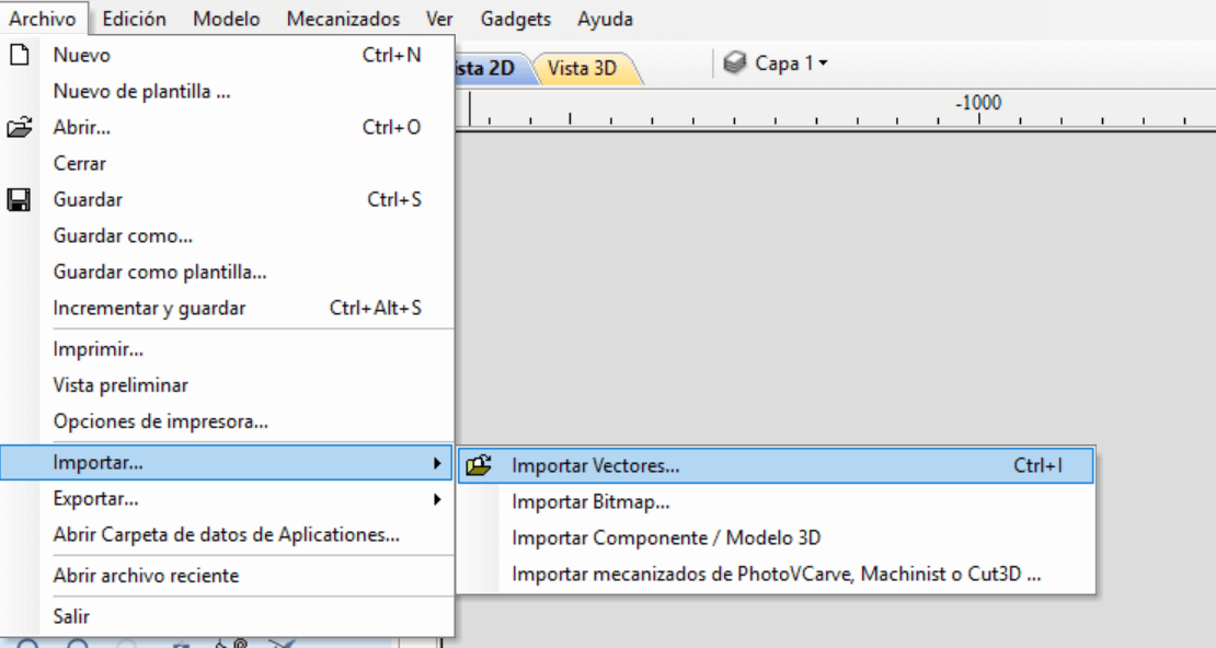
The next thing to do is to import a vector, for that we go to the menu Open - Import - Import vectors or simply "Ctrl + I". Another way to import a vector is directly from the file operations menu and press "Import document", as shown in the figure above.
Once the pieces of our design have been added and the tools to transform objectives and/or move and position have been used, we proceed to close the drawing vectors since these are separate lines. To close them, simply select all the figures and press the "close vectors" icon.
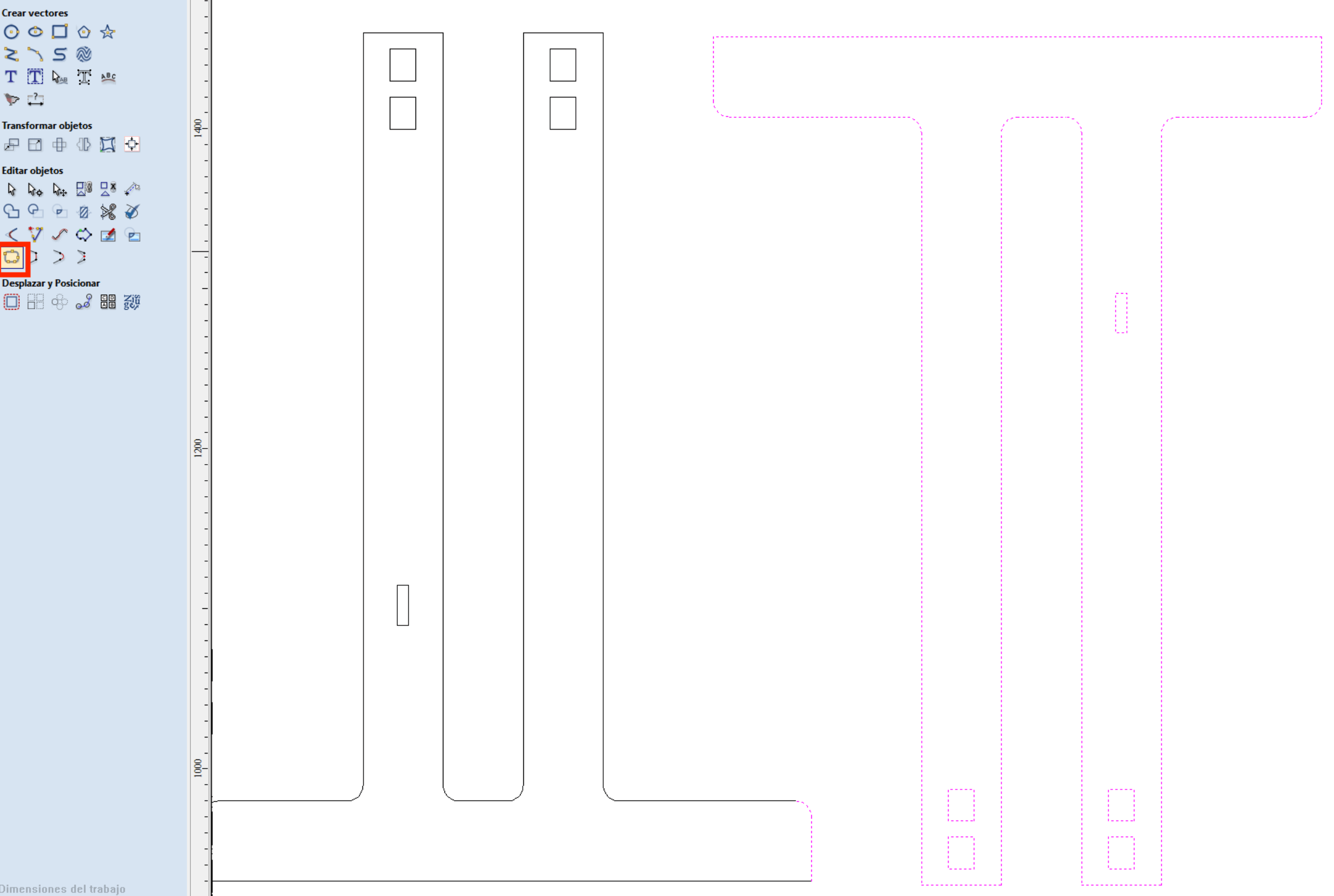
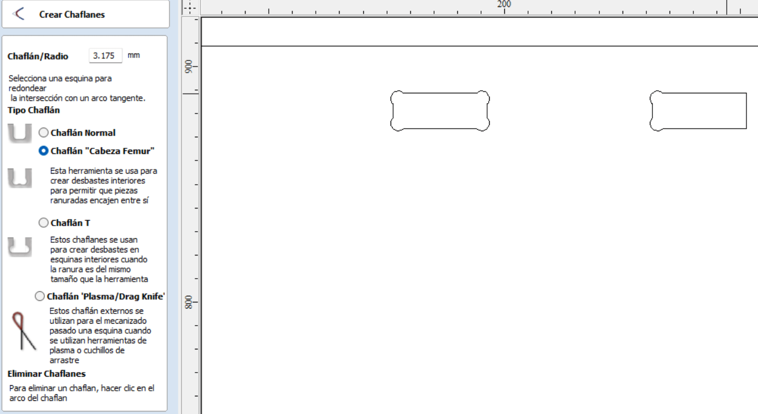
When the vectors are closed, we proceed to select "Internal chamfer", this will open a new window containing the radius of the chamfer. It is
important at this point to know what size the mill will be, in our case it will be \(\frac{1}{4}''\). The value of the chamfer/radius will be
half of the mill in \(mm\).
Once the "chamfer" tool is selected, we select all the internal corners of our design to make the chamfer as shown in the image.
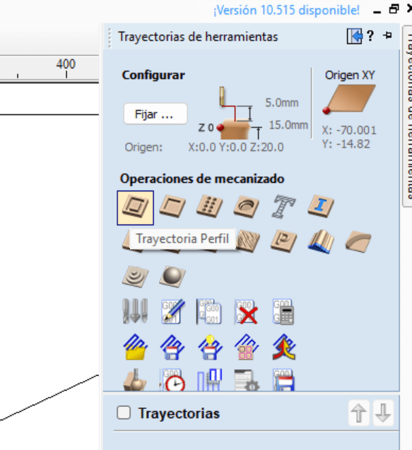
On the right side at the top of our work area, there is a tab called "Toolpath", in that tab there are a series of icons with different functions. We select the profile path.
Before continuing, it is important to have different considerations of our tool such as "Cutting feed (IPR) or Spindle speed (RPM)", the following link shows a page to calculate values.
You can also consult the following table "Feeds and Speeds".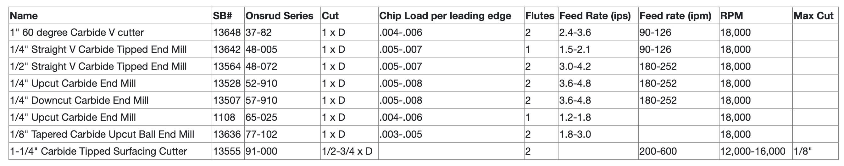
Once we have consulted the above, we continue with the profiling tool, the first thing to do is select the depth of the cut, where the
initial point would be \(0,\) since it is the origin and the final depth of "\(15.2\)" (depends on the warping of the material), since
we need it to exceed the thickness of the material to ensure the cut.
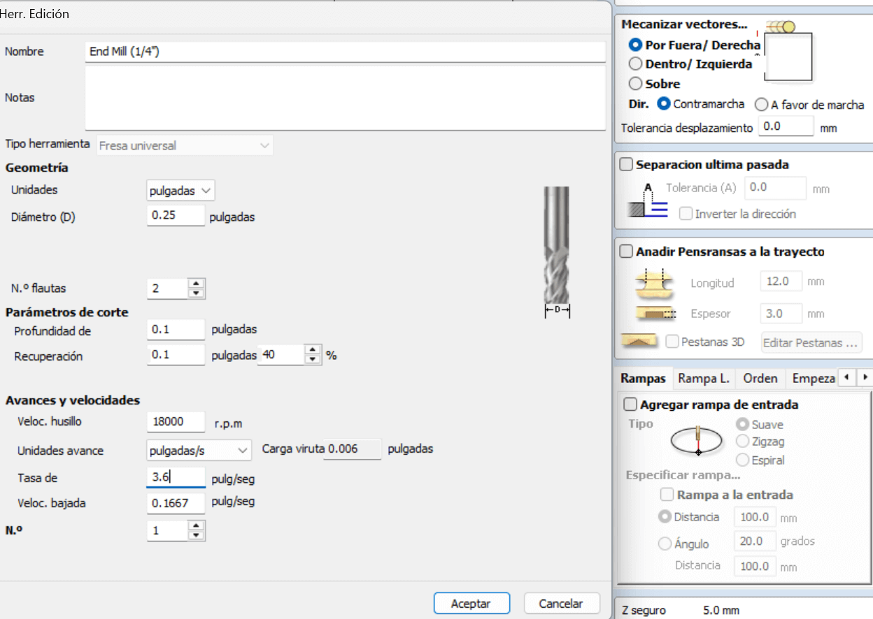
The next step is to select the tool, so we choose "edit" to set the values of our tool with the help of the information above. After
selecting the tool, the vector machining continues, in which 3 options are presented:
- Outside - If it is an external cut
- Inside - If they are internal cuts
- Above - Above the middle of the line
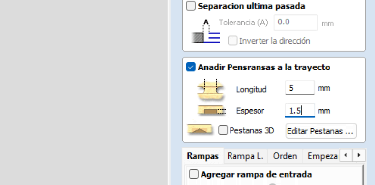
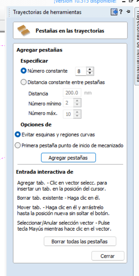
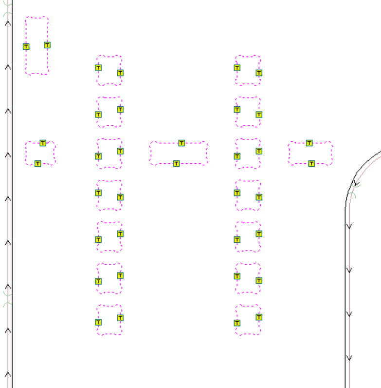
The next step is to add tabs, it is important not to make the tabs too thick (they cannot break) or too thin (they could break during machining), once placed we select edit tabs, which opens a new window where we place the number of tabs, these tabs will be seen in our selected drawing. If any tab is not in a suitable place, with one click we can remove it and with another click place it in the desired place.
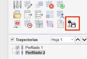
If everything is correct, we press close in the tab window and press calculate. In the 3D model window (top left) it shows us the short path of our tool.
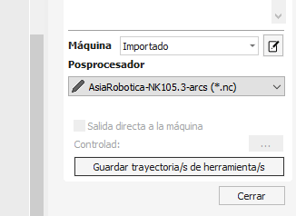
The last step is to save the path and select the router. Asia Robotica shop-1325 .
CNC Router
The CNC Router is a computer-controlled machine, the path of the machine uses numerical control, which sends the coordinates from the computer by means of G-code. The most important commands of the G-code are shown in the following link.
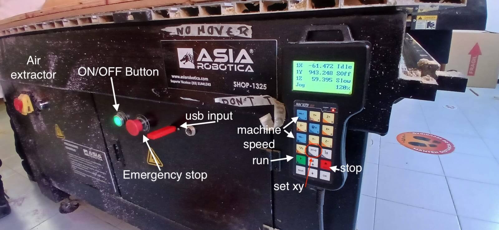
Nowadays there are many types of "CNC" machines, in the following link some are mentioned. We will use the CNC router, it is important to note that we need a "Router Bit" to be able to work, each of these has a particular purpose, so in the following link some are mentioned for woodworking.As mentioned above, we will be using the Asia Robotica shop-1325 , so the images below show the parts that make it up.

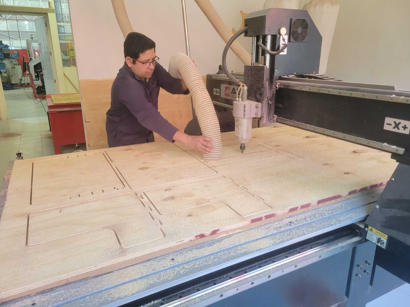
FIRST STEPS IN THE CNC ROUTER
The first thing to do is to place the tool in the chuck as shown in the video.
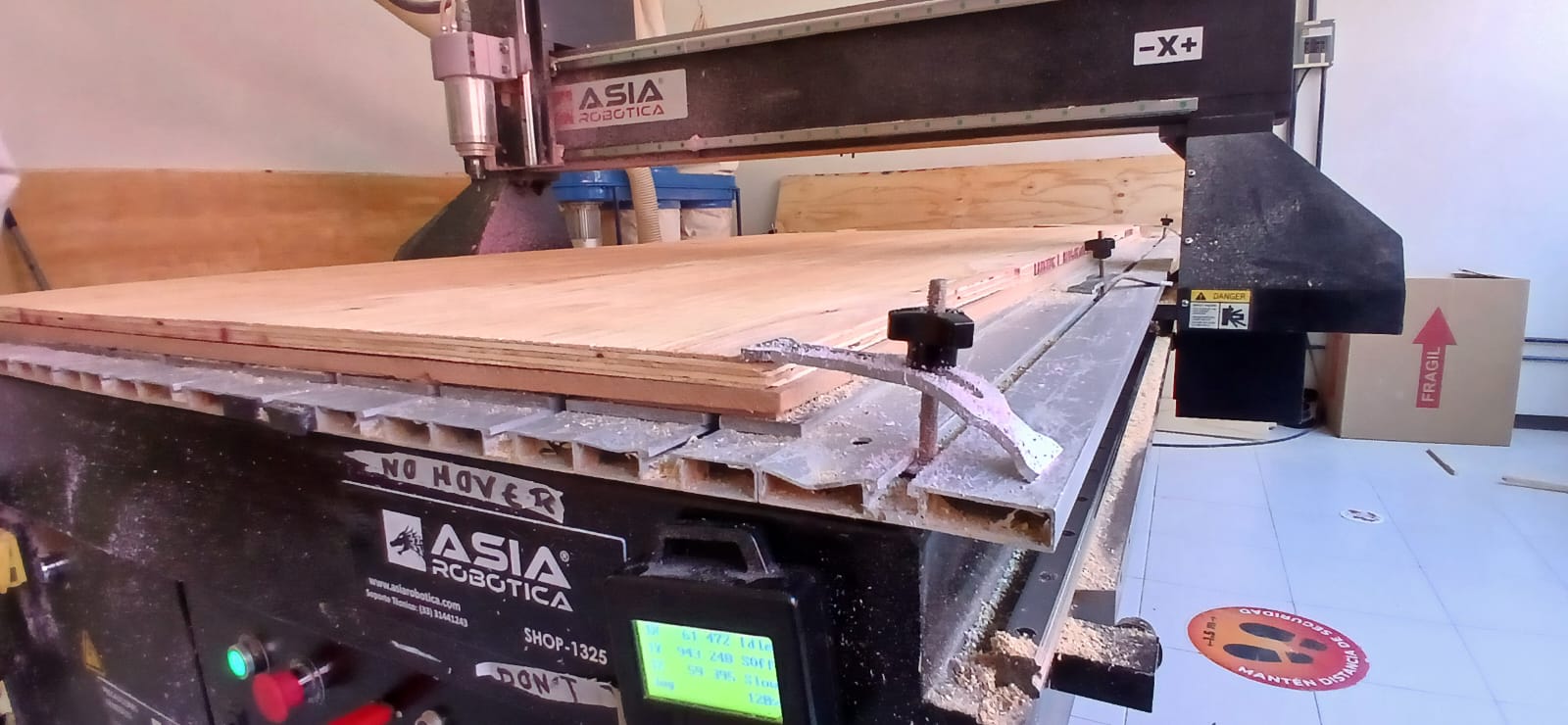
The next step is to place the board, securing it to the plank with the pins that are located along it, placing at least one pin in each corner of the board.
Next, we will set our origin, for that we use the master control. We start by moving the "x" and "y" axes, leaving them in a position that avoids the pins that fix the wood, if the position is correct, we press "XY = 0" so that this point is the origin. We can see that now the screen marks the position of "X" and "Y" at 0. The next step is to set the "Z" position, for that with the control we must lower until the cutting tool touches the material, for that it is necessary to know that in the "z" axis we have two types of movements, continuous and stepwise. To make the stepwise movement, that is the one that suits us to better control the "Z" axis, we only press "shift".
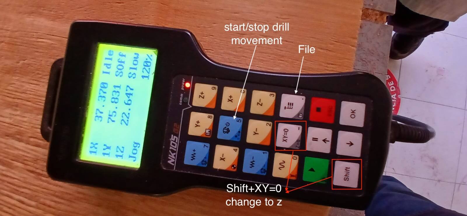
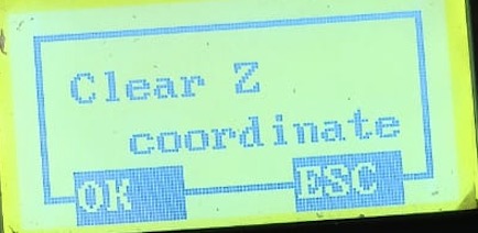
To set the "z" axis, press the key combination "Shift + XY = 0", this will change the screen and then we should press ok.
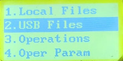
Once the previous steps have been completed, it is time to load the program. To do this, press the "File" key to open a new window. There, select "USB" and search for the file. Once found, press the number "2" to copy.
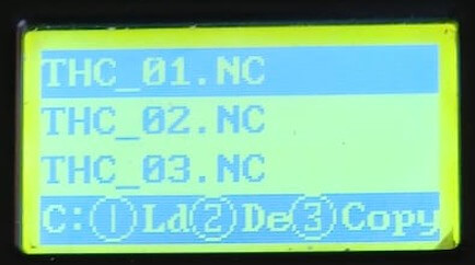
We go back to "File" and go to Local File where we paste the file copied from the USB, press the number "1" to load. Once the file is loaded, we press "run" to start cutting.
It is important to vacuum while the router is running to avoid excess sawdust.
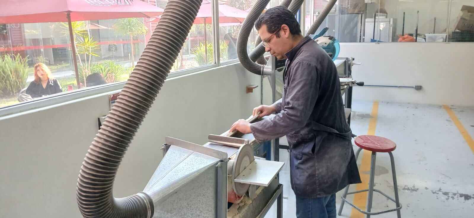
ASSEMBLY
Before beginning assembly, all parts must be sanded to remove imperfections in the wood.
Once all the pieces are sanded, the assembly process begins. To do this, you must have a strategy of how the pieces should go. Each of the designed pieces contains tabs or holes that allow the different pieces that make up the desk to fit together. The number of pieces needed is listed below.
- 2 Desk legs
- 2 Sides of the desk
- 1 Cover
- 1 Bottom base
- 8 stakes that set the height of the table
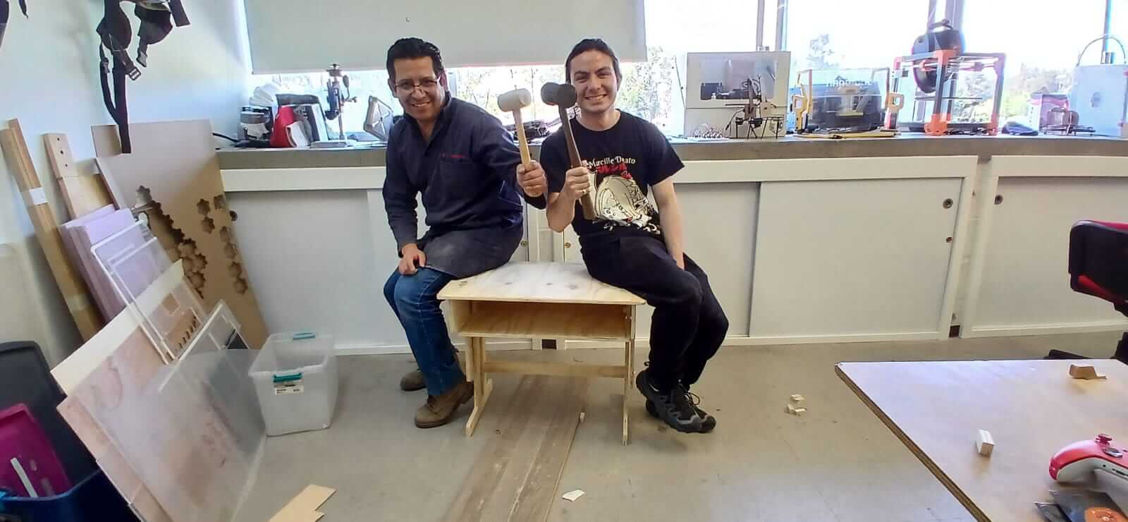
Below is the entire assembly process and the final result.
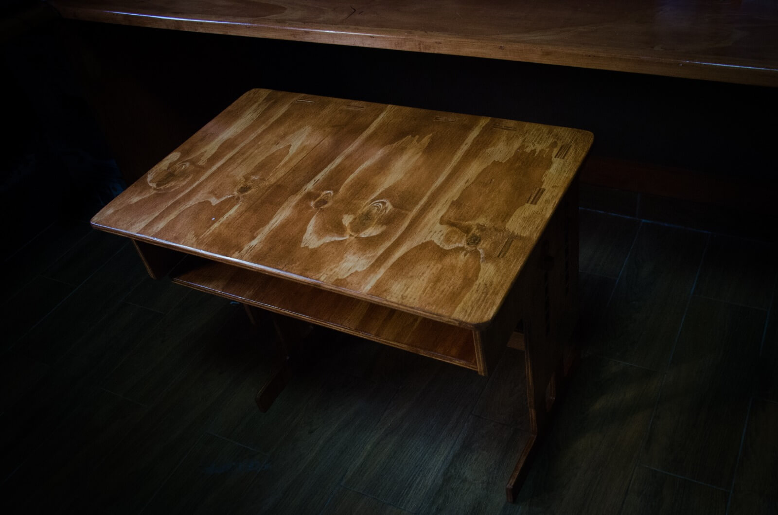
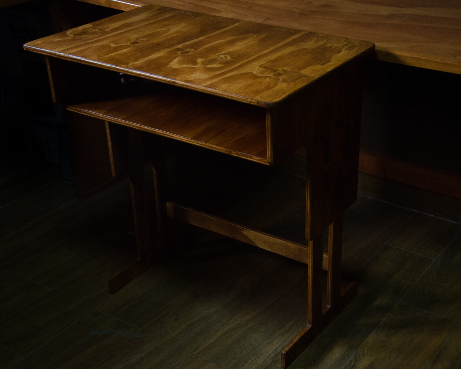
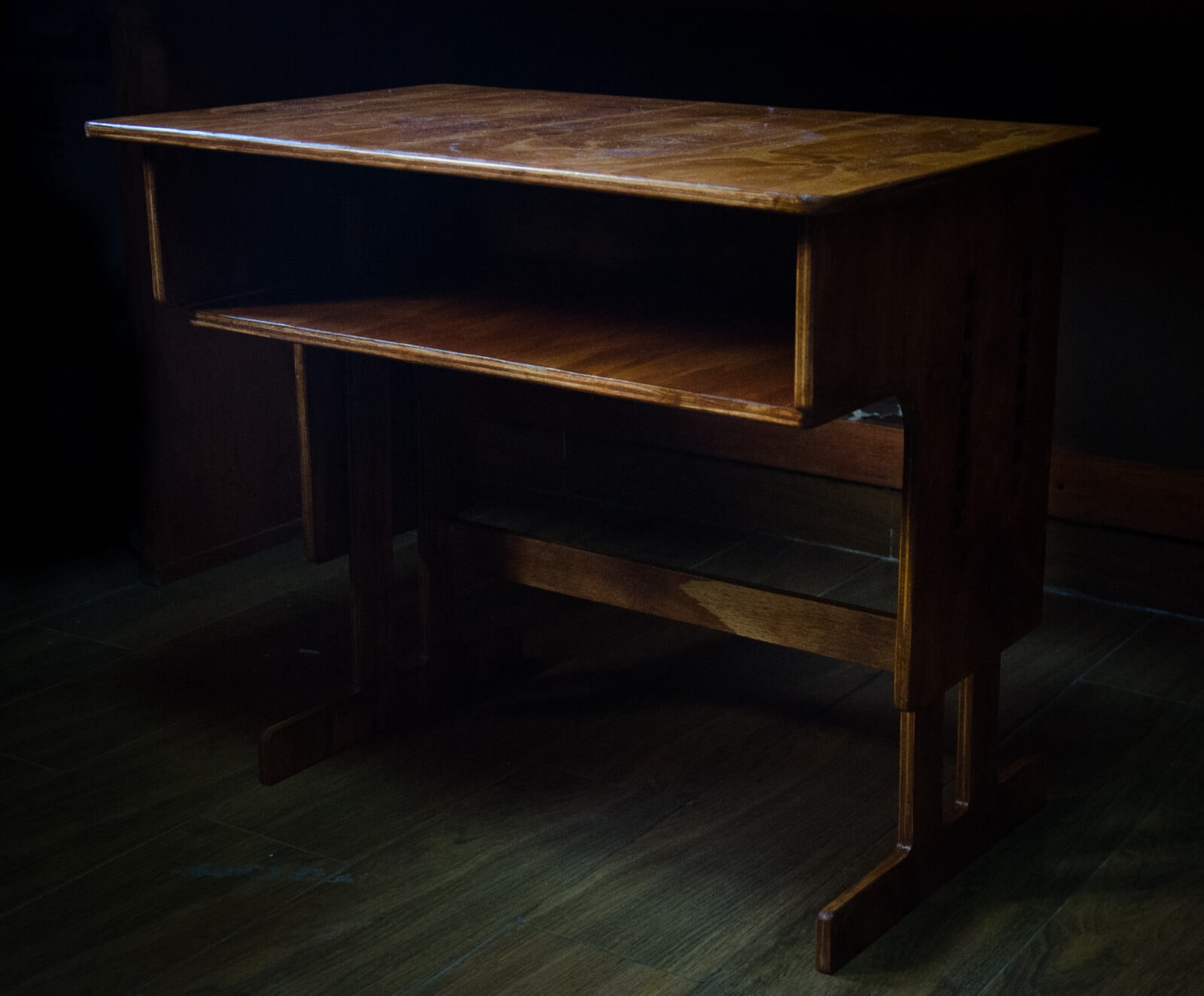
Final Result
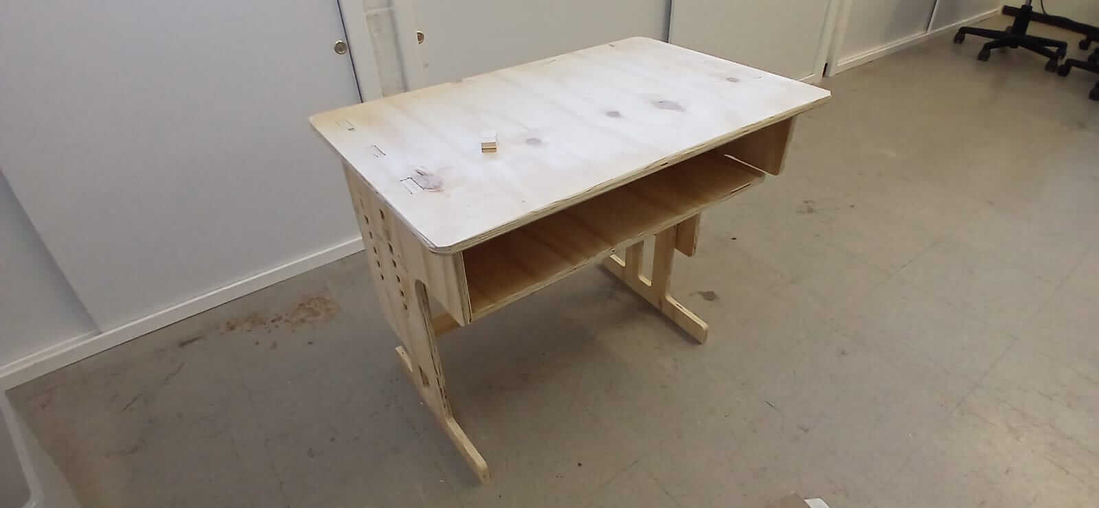
The following images show the minimum and maximum height that the desk can have depending on the height of the user. They also show the result after sanding, sealing, painting and varnishing.
Learning outcome
This week we learned about the use of the router and the importance of good planning. Not only a good design is important, but the path of the machine, whether the wood is warped, the length of the cutting tool, etc. must also be considered.
Acknowledgment
Thanks to my local instructor Oliver, who helped me solve some problems that arose.