Networking and Communications
This week focuses on exploring and understanding different communication protocols used between microcontrollers and peripheral devices. Communication interfaces are a fundamental part of digital systems, and each protocol has distinct advantages depending on speed, complexity, and number of connected devices.
Communication Protocols
UART (Universal Asynchronous Receiver/Transmitter)
UART is a serial communication protocol that enables full-duplex data transmission. It uses two lines: TX (transmit) and RX (receive), and does not require a clock signal. The baud rate must be the same on both devices. UART is widely used due to its simplicity, but is typically limited to point-to-point communication.
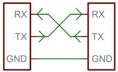
Figure 1: Wiring for UART.
SPI (Serial Peripheral Interface)
SPI is a high-speed synchronous protocol used for short-distance communication. It involves a master-slave architecture with four lines: MISO (Master In Slave Out), MOSI (Master Out Slave In), SCK (Serial Clock), and SS (Slave Select). SPI is capable of full-duplex communication and is faster than I²C but requires more pins.
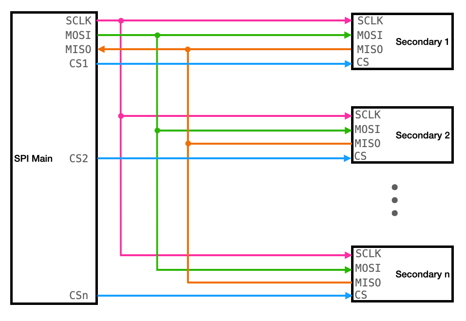
Figure 2: Wiring for SPI.
I²C (Inter-Integrated Circuit)
I²C is a synchronous, multi-master, multi-slave, packet-switched, single-ended, serial communication protocol. It uses only two lines: SDA (Serial Data Line) and SCL (Serial Clock Line). I²C is ideal for communication between components on the same board, supporting multiple devices with unique addresses. While slower than SPI, it is more scalable and requires fewer connections.
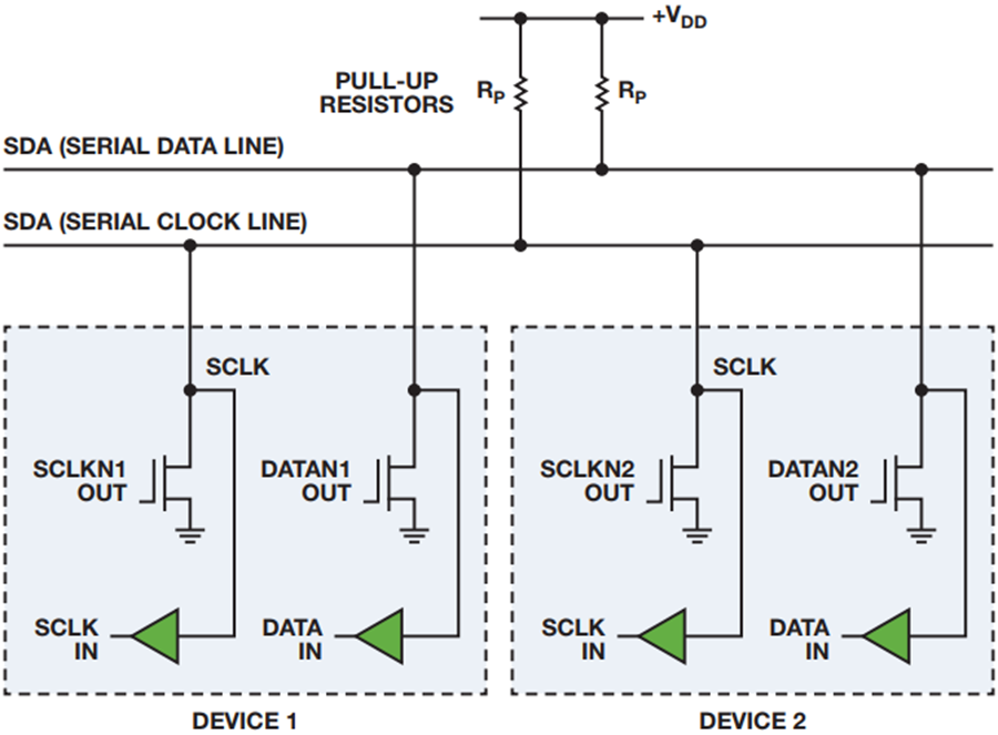
Figure 3: Wiring for I2C.
Wireless Communication Protocols
In addition to the wired communication protocols such as I2C, UART, and SPI, several wireless communication methods are commonly used in embedded systems and microcontroller-based projects. These methods provide the advantage of mobility and remote data exchange without physical connections.
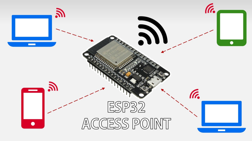
Wi-Fi (Wireless Fidelity)
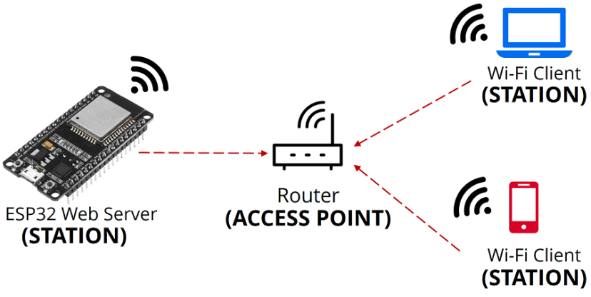
Wi-Fi is a popular wireless communication protocol that enables devices to connect to a network and exchange data over the internet or local networks. It is based on the IEEE 802.11 standards and typically operates in the 2.4 GHz and 5 GHz frequency bands. In the context of microcontrollers like the ESP32, Wi-Fi is frequently used to transmit sensor data to web servers, receive control commands, or integrate with cloud platforms.
Wi-Fi communication requires configuring the microcontroller to connect to an access point (router), assigning an IP address, and using protocols such as HTTP, MQTT, or WebSockets to handle data exchange.
Bluetooth
Bluetooth is a short-range wireless communication technology suitable for applications that require simple peer-to-peer communication. It operates in the 2.4 GHz ISM band and is often used for device-to-device communication within a short range.
The ESP32 also supports Bluetooth Classic and BLE (Bluetooth Low Energy), which is suitable for transmitting small amounts of data with low power consumption. Typical use cases include mobile-to-device control, fitness trackers, or short message broadcasting.
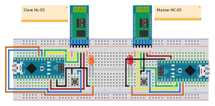
Figure 6: Bluetooth, basically an UART with key and wireless comunication.
Comparison of Wired and Wireless Communication Protocols
| Protocol | Type | Typical Use Case | Advantages |
|---|---|---|---|
| I2C | Wired | Short-distance communication between chips | Simple, supports multiple devices on two wires |
| SPI | Wired | High-speed communication with peripherals | Fast and reliable |
| UART | Wired | Serial communication between devices | Standard, asynchronous communication |
| Wi-Fi | Wireless | Long-range remote control or IoT | No physical connection needed, internet-enabled |
| Bluetooth | Wireless | Short-range device communication | Low power, easy pairing |
For more info, here is the group assignment!
In this week, I will establish communication between two microcontrollers, the ESP32 (board made in week8) and a RP2040 using the I²C protocol. The ESP32 will act as the I²C master and the XIAO RP2040 will function as the slave. The ESP32 will send instructions in the form of text strings to the RP2040. Based on these instructions, the RP2040 will control a built-in Neopixel LED and a servomotor connected to pin 0.
Designing a PCB using the Xiao RP2040 does not require many complex considerations. Since the board already integrates the RP2040 microcontroller in a compact format, it is equipped for multiple operations out of the box. Therefore, the only task is to connect the necessary pins for your application. Its modularity allows for seamless replication using other microcontrollers like the RP2040 or ESP32, maintaining the same pinout and functions during programming. This PCB was designed primarily for general purposes.
.png)
_Result.PNG)
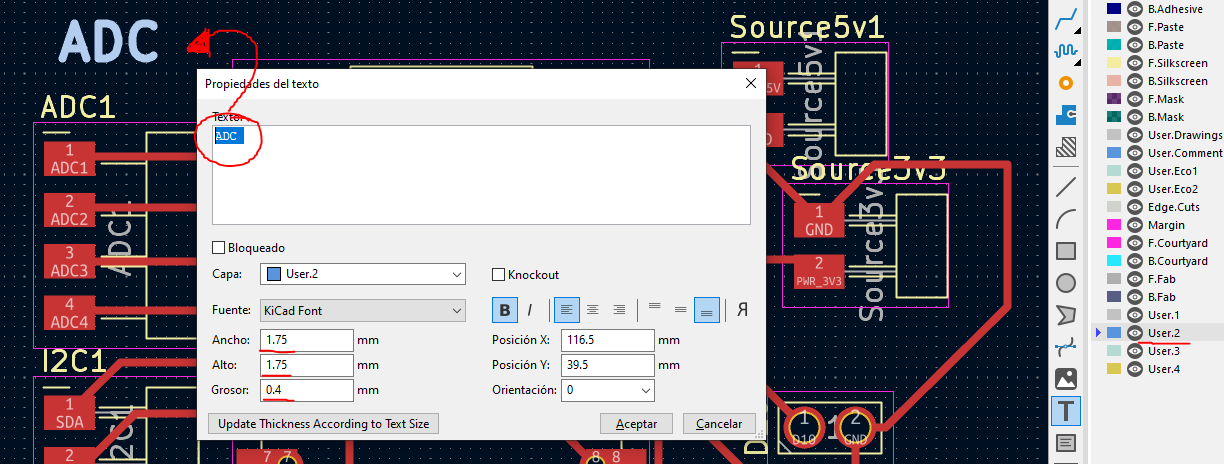
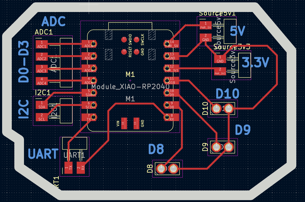
Figure 11: XIAO pcb.
Since I do not plan for the Xiao RP2040 to be my main microcontroller, I only added the essential pull-up resistors. As established during week 8, my ESP32 already includes two pull-up resistors on pins 21 (SDA) and 22 (SCL), enabling I2C communication without additional components.
In previous PCBs I designed during the Fab Academy, I had never used through-hole components. For this reason, I decided to include at least six through-hole pads in this PCB to learn how to configure and solder them properly.
  #include Wire.h

  // === I2C slave address ===
  // This must match the address defined in the RP2040 code (I2C slave)
  #define SLAVE_ADDR 0x08

  // Buffer to accumulate incoming serial characters
  String serialBuffer = "";

  void setup() {
    Serial.begin(115200);  // Start serial communication with PC for debug/input
    Wire.begin();          // Start I2C in master mode (ESP32 as master)
    Serial.println("ESP32 ready. Type a command:");
  }

  void loop() {
    // Continuously read serial input and process when newline is detected
    readSerialCommand();
  }

  // === Read characters from Serial input ===
  // Accumulate characters until a newline '\n' is received
  // Then send the full command via I2C to the slave
  void readSerialCommand() {
    while (Serial.available()) {
      char c = Serial.read();

      if (c == '\n') {
        serialBuffer.trim();  // Remove any whitespace or newlines from start/end
        if (serialBuffer.length() > 0) {
          sendI2CCommand(serialBuffer);  // Send valid command via I2C
        }
        serialBuffer = "";  // Clear the buffer for next input
      } else {
        serialBuffer += c;  // Append character to command buffer
      }
    }
  }

  // === Send a command string to the I2C slave ===
  // Converts the String to a byte array and sends it via I2C
  void sendI2CCommand(String command) {
    Serial.print("Sending via I2C: ");
    Serial.println(command);  // Echo command to serial for confirmation

    Wire.beginTransmission(SLAVE_ADDR);                     // Begin communication with slave
    Wire.write((const uint8_t*)command.c_str(), command.length());  // Send command as byte array
    Wire.endTransmission();                                 // End transmission
  }
The code sets up an ESP32 as an I2C master, enabling it to send commands to an I2C slave device; in this case, as said before, an RP2040. The communication begins with the declaration of the I2C slave address, which must match the address defined on the slave side. In this case, the address is set to 0x08. Mismatched addresses between master and slave will result in failed communication, so it is critical to ensure both devices are configured identically in this regard.
The setup function initializes both serial communication, used for debugging and user input via the Serial Monitor, and I2C communication. The Wire.begin() function starts the I2C master mode on the ESP32, allowing it to initiate transmissions to the defined slave device.
The loop continuously monitors the serial input. It captures characters typed by the user and stores them in a buffer until a newline character ('\n') is received, which signals the end of the command. This approach allows complete strings to be built from user input before any I2C transmission occurs.
Once a complete command is received, the sendI2CCommand() function is called. This function first echoes the command back to the serial monitor for confirmation, which is useful for debugging. It then initiates communication with the slave by calling Wire.beginTransmission() with the defined address. The command string is converted into a byte array using command.c_str() and transmitted via Wire.write(). Finally, Wire.endTransmission() concludes the I2C message.
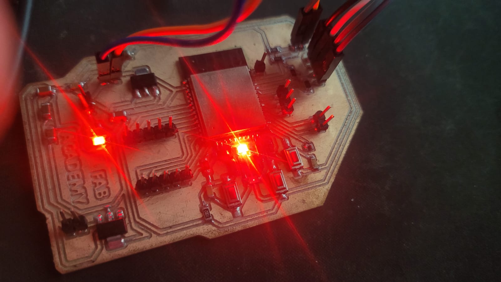
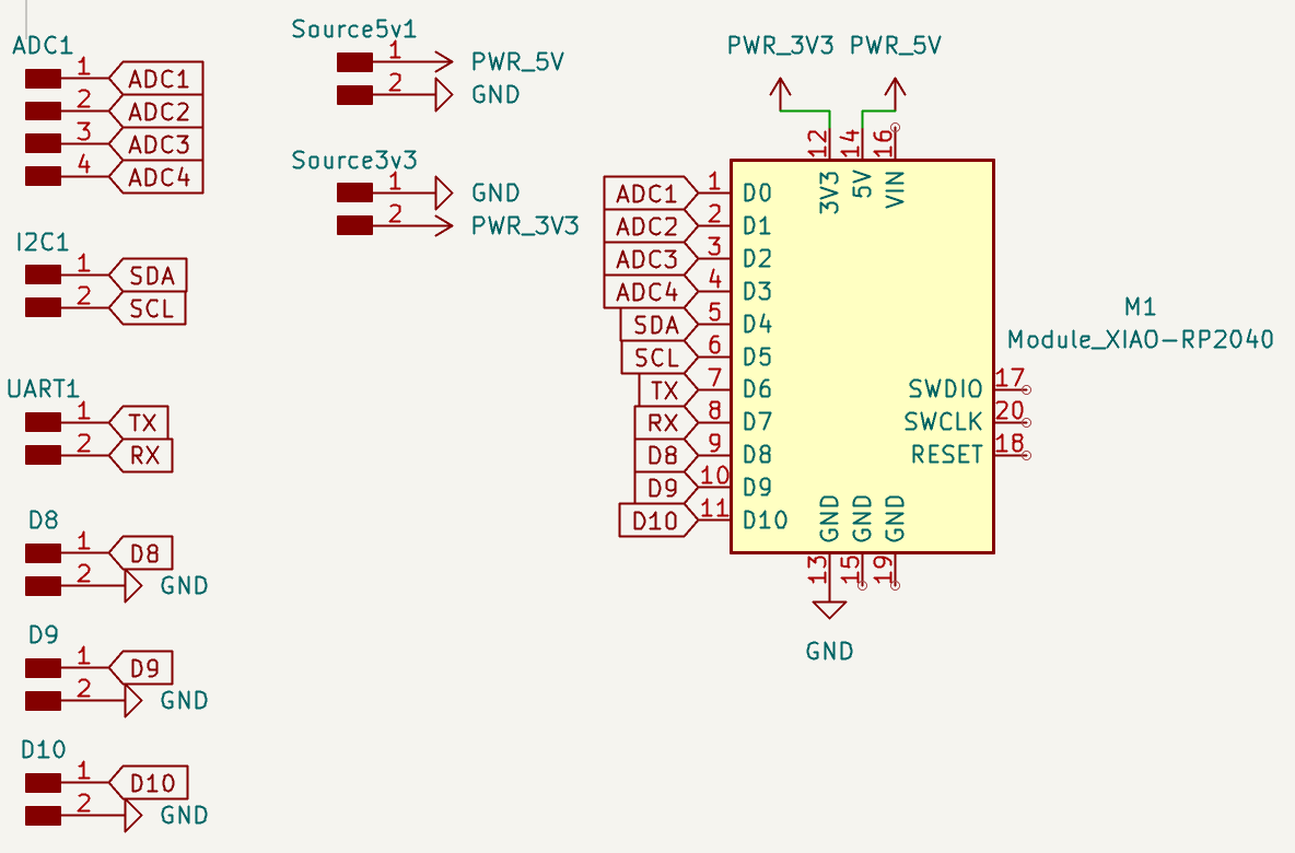
Figure 12: ESP32 connections.
  #include Wire.h
  #include Adafruit_NeoPixel.h
  #include Servo.h

  // === I2C and Hardware Pin Definitions ===
  #define I2C_ADDRESS 0x08       // I2C slave address (must match master ESP32)
  #define SERVO_PIN D0           // GPIO pin for the servo motor
  #define NEOPIXEL_PIN 12        // Data pin for the built-in NeoPixel
  #define NEOPIXEL_PWR 11        // Pin to enable power to the NeoPixel (HIGH = ON)
  #define NUMPIXELS 1            // Only one NeoPixel
  #define MAX_COMMAND_LENGTH 32  // Maximum length of received command to prevent buffer overflow

  // === Objects ===
  Servo SM;  // Servo motor instance
  Adafruit_NeoPixel pixel(NUMPIXELS, NEOPIXEL_PIN, NEO_GRB + NEO_KHZ800);  // NeoPixel strip (1 pixel)
  String receivedCommand = "";  // Buffer for received I2C commands

  void setup() {
    // === I2C Initialization ===
    Wire.setSDA(D4);             // Set SDA to GPIO D4
    Wire.setSCL(D5);             // Set SCL to GPIO D5
    Wire.begin(I2C_ADDRESS);     // Start I2C as slave with specified address
    Wire.onReceive(receiveEvent); // Callback when data is received

    // === Serial Debug ===
    Serial.begin(115200);
    Serial.println("XIAO RP2040 I2C Slave ready");

    // === NeoPixel Power Control ===
    pinMode(NEOPIXEL_PWR, OUTPUT);
    digitalWrite(NEOPIXEL_PWR, HIGH);  // Enable power to the NeoPixel
    delay(10);  // Wait for power to stabilize

    // === NeoPixel Initialization ===
    pixel.begin();         // Initialize NeoPixel
    pixel.setBrightness(50); // Set brightness (0-255)
    pixel.show();          // Clear pixel (turn off)

    // === Servo Initialization ===
    SM.attach(SERVO_PIN);  // Attach servo to defined pin
    SM.write(90);          // Start at neutral position (90°)
  }

  void loop() {
    // If a new command was received
    if (receivedCommand.length() > 0) {
      Serial.print("Received: ");
      Serial.println(receivedCommand);

      // === Process LED Color Commands ===
      if (receivedCommand == "red")        setColor(255, 0, 0);
      else if (receivedCommand == "green") setColor(0, 255, 0);
      else if (receivedCommand == "blue")  setColor(0, 0, 255);
      else if (receivedCommand == "white") setColor(255, 255, 255);
      else if (receivedCommand == "purple")setColor(128, 0, 128);

      // === Process Servo Angle Command ===
      else if (receivedCommand.startsWith("Angle:")) {
        int angle = receivedCommand.substring(7).toInt();  // Extract angle value
        angle = constrain(angle, 0, 180);                  // Limit between 0° and 180°
        SM.write(angle);                                   // Move servo
        Serial.print("Servo set to ");
        Serial.println(angle);
      }

      receivedCommand = "";  // Clear buffer after processing
    }
  }

  // === I2C Receive Handler ===
  void receiveEvent(int howMany) {
    receivedCommand = "";  // Reset command buffer

    // Read incoming I2C characters
    while (Wire.available()) {
      char c = Wire.read();

      // Only store characters if within max buffer size
      if (receivedCommand.length() < MAX_COMMAND_LENGTH) {
        receivedCommand += c;
      } else {
        // Discard extra characters to prevent overflow
        Wire.read();
      }
    }
  }

  // === Set NeoPixel RGB Color ===
  void setColor(uint8_t r, uint8_t g, uint8_t b) {
    pixel.setPixelColor(0, pixel.Color(r, g, b));  // Set color for pixel 0
    pixel.show();  // Update pixel to show the new color
  }
This program is designed to run on a XIAO RP2040 microcontroller as an I2C slave. It handles two main peripherals: a servo motor and a NeoPixel RGB LED. Communication is managed over I2C using the Wire library, and the device listens for commands sent from an I2C master such as an ESP32. The slave address must be consistent with the one defined on the master, in this case 0x08.
The setup function initializes I2C communication with custom-defined SDA (D4) and SCL (D5) pins and sets the slave address accordingly. It also attaches a callback function (receiveEvent) to handle incoming I2C data. The system also prepares the NeoPixel by enabling its power pin and setting brightness and clears any previous state. Similarly, the servo is initialized and positioned at its neutral angle (90 degrees).
In the main loop, the code constantly checks whether a new command has been received. If so, it parses the command to determine whether it corresponds to a known LED color ("red", "green", "blue", etc.) or a servo position (e.g., "Angle:120"). Color commands invoke the setColor function, which updates the NeoPixel with the desired RGB values. Angle commands are parsed and constrained to the 0-180° range to protect the servo mechanism.
The receiveEvent function reads incoming bytes via I2C and appends them to a string buffer, ensuring that the total length remains within safe limits (MAX_COMMAND_LENGTH = 32) to prevent overflow. Once a valid command is received, the main loop takes care of executing the corresponding physical action.
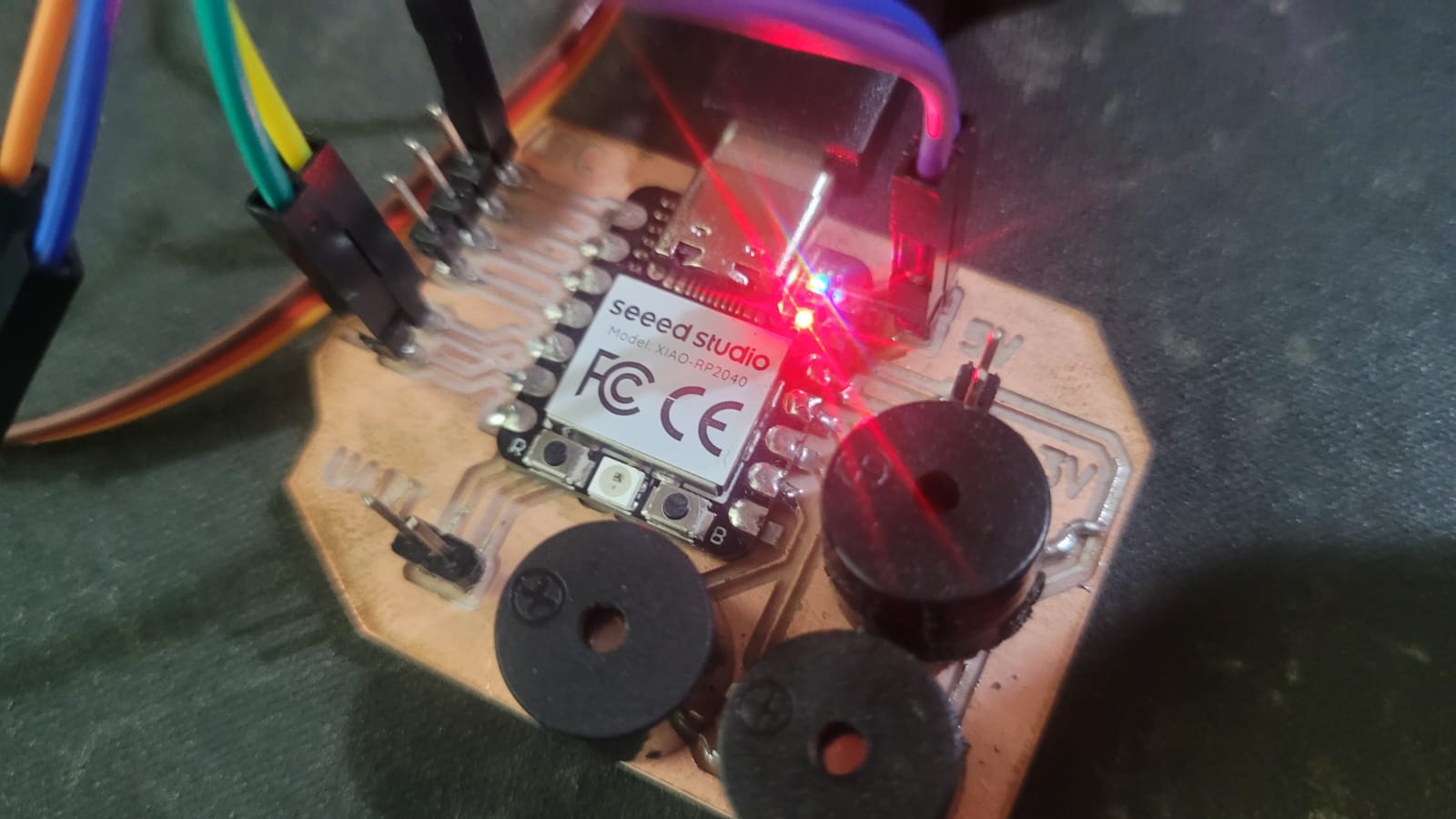
Figure 13: XIAO connections.
.jpeg)
Figure 14: The XIAO works without the USB C port beacause it recieves the instructions from the I2C bus (except the servomotor, it requires more voltage).
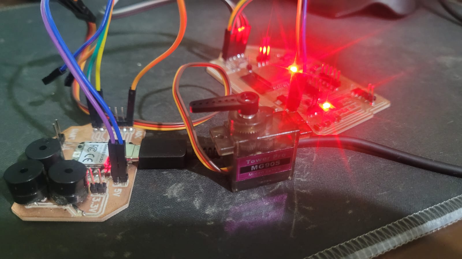
HEROSHOT! COMUNICATE.
Learnings
Beyond deepening my understanding of communication protocols between different microcontrollers and devices, this week I learned how to properly configure a microcontroller as an I2C slave. Although I usually prefer UART communication due to its simplicity and practicality, I recognize the versatility of I2C. I had previously used this protocol to communicate with sensors and modules, but not as part of a bus with microcontrollers acting as slaves. While I had attempted this configuration before, it was not clear to me. But now yes.
Additionally, I learned how to drill and solder through-hole components on a PCB. For this board, I soldered three old buzzers I had lying around from university projects (they don’t work). While I could have connected other devices or modules to the available pins, I mainly wanted to practice soldering these components. I now understand that precise spacing and correct pin diameters are critical, and I would recommend others to consider these factors during layout.