Electronics Production
Electronics production involves designing, testing, and manufacturing electronic systems, from prototypes to final products. In week 6 we already did a design of a PCB, and, in the assignment, I already mentioned how to planificate a PCB. But to summarize, it starts with defining the project's requirements and selecting the right components based on technical specifications. Once that’s done, the schematic design is created to show how everything will connect. Then, the next step is to make the PCB. First, the design is transferred onto the board where the copper is etched away to create the circuit. Then, holes are drilled for the components that go through the board, and pads are prepared for the surface-mount components. After that, the components are soldered onto the board, either manually or with automated machines. Finally, the board is tested to make sure everything works.
This week, I designed two boards. The first was an updated version of the one I worked on in week 6. The changes were not due to issues with the circuit design but were made to facilitate the manufacturing process. The second board was a quick design for Attiny412. I created two boards because I did not have an ESP32 Wroom for my original design, despite thinking I had one. I placed an order for it through Digikey, but it will not arrive until Wednesday. So, to have something to work with this week, I decided to design a simple yet effective board for the Attiny412, a microcontroller I had been interested in for some time. With all this, I simply want to point out that it is very important to have all the components on hand.
Anyway, both PCBs were created using the Roland SRM-20, a mini-CNC milling machine available in the lab, and I was responsible for soldering both. Here are the specifications of the SRM-20 and the cutting tools used:
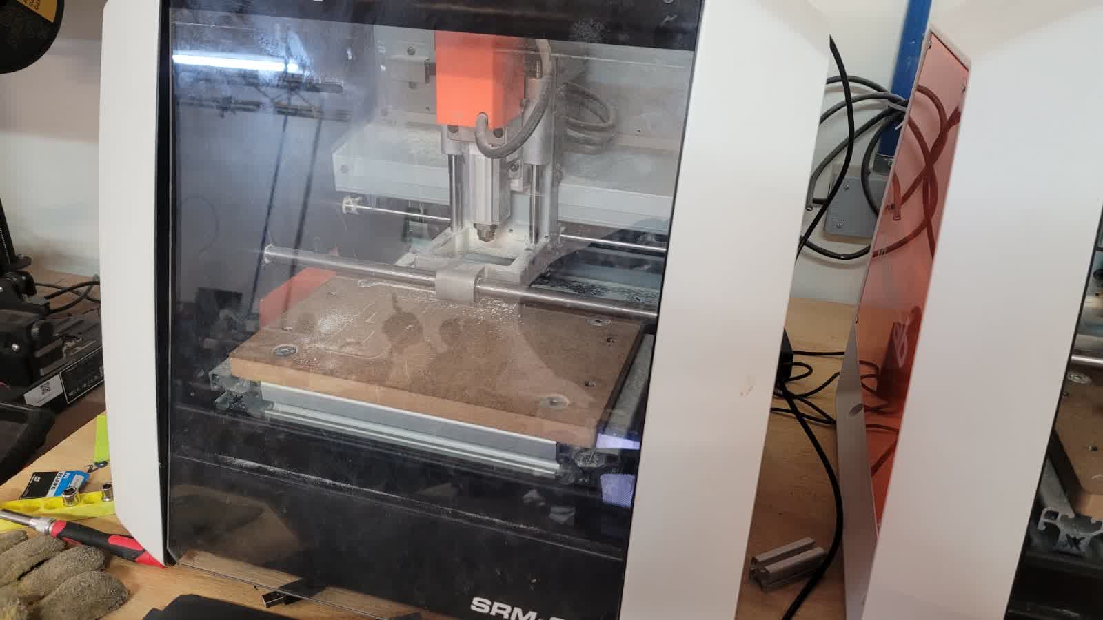
Figure 1: Roland SRM-20.
- Manufacturer: Roland
- Model: SRM-20
- Specifications: 203x152x60 mm working area, 1800 mm/min feed rate, 0.001 mm step precision, 7,000 RPM spindle speed
- Applications: Precision three-axis machining, including PCB fabrication with a feature size down to 0.25 mm, and machinable wax for tooling in molding and casting
- Engraving Bit: 0.4 mm
- Milling Cutter: 2 mm
For more info go to our group assignment
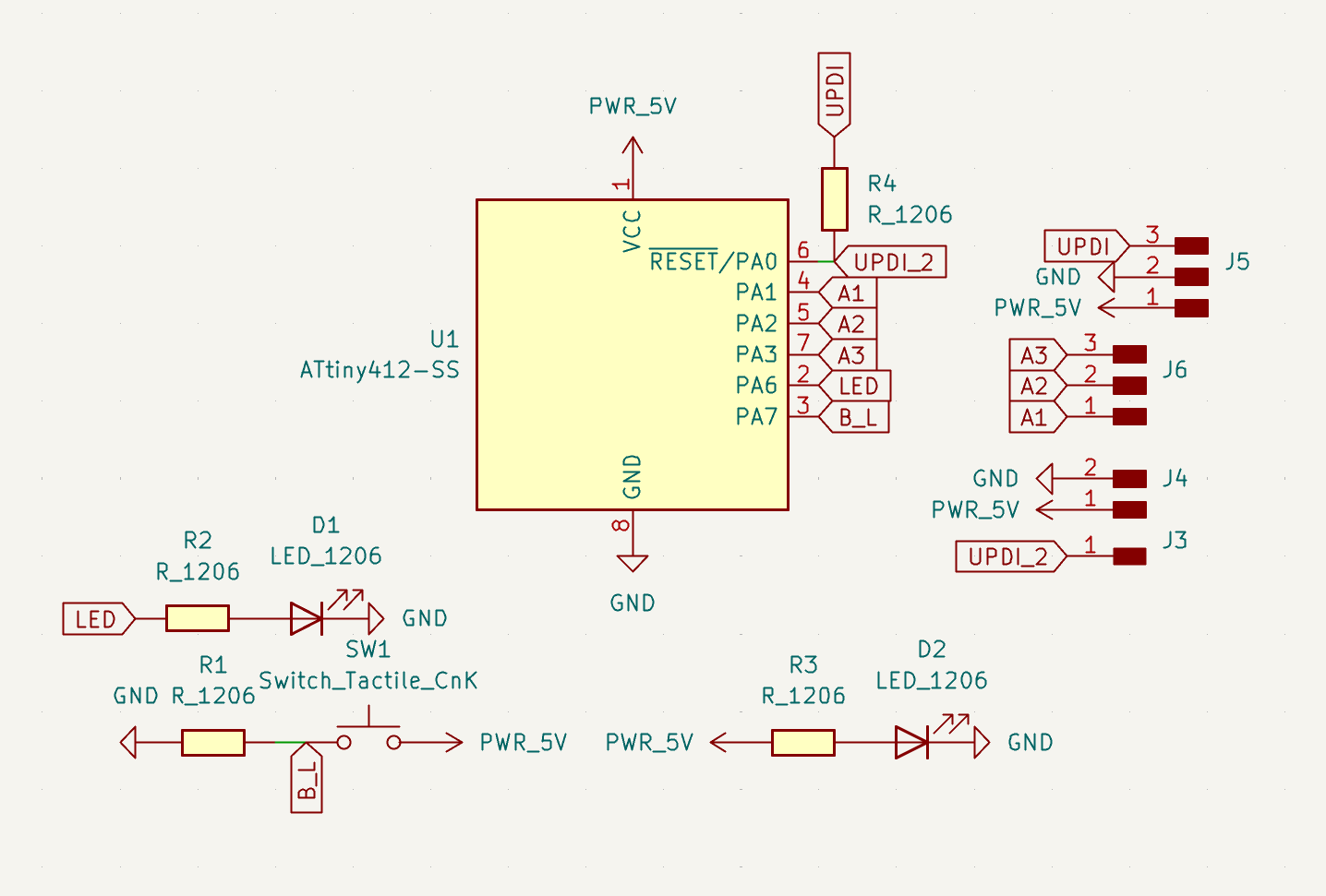
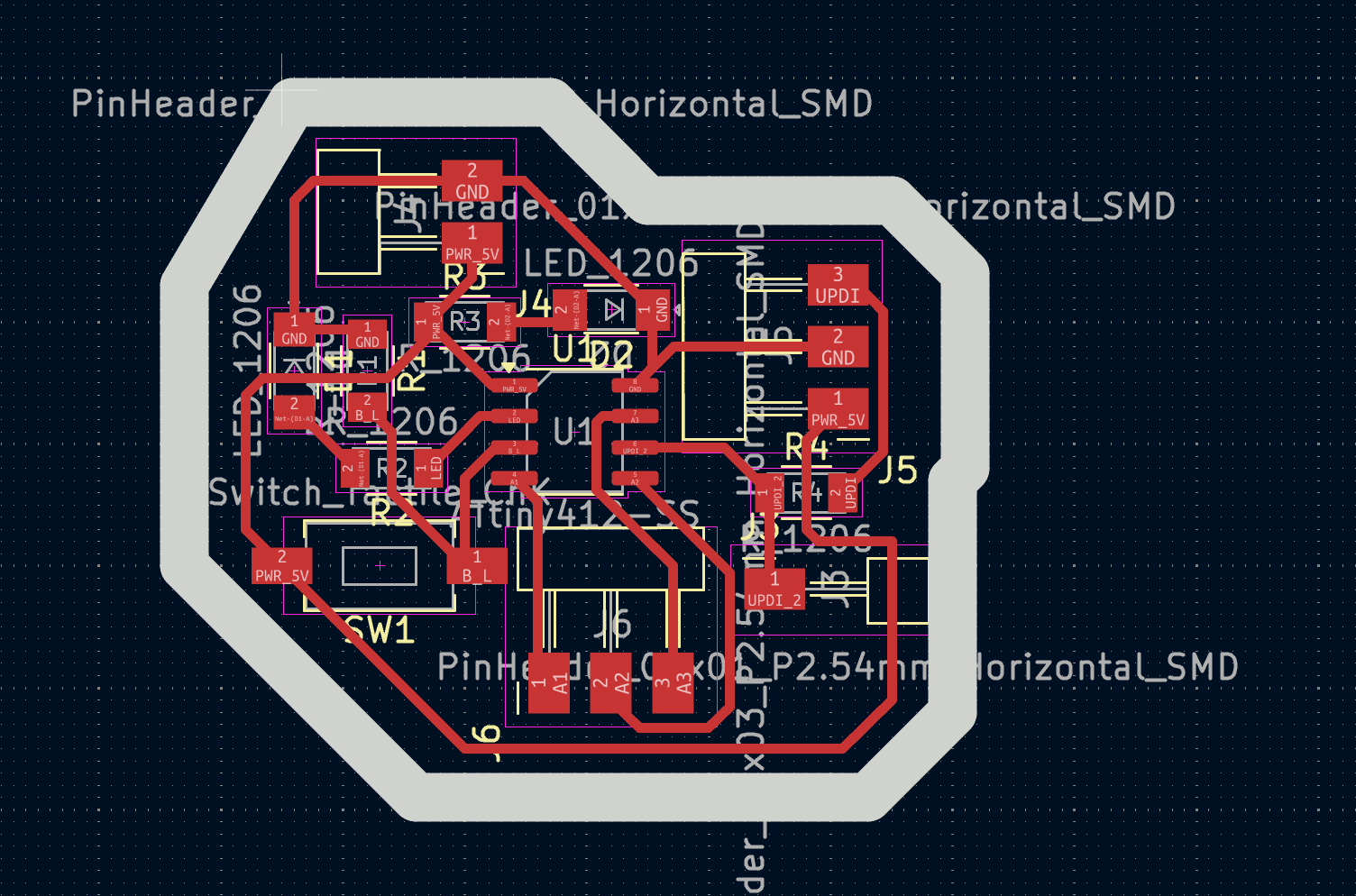
PCB Design for ATtiny412
Designing a PCB for the ATtiny412 does not involve much complexity from an electronic standpoint. After all, it is simply an AVR microcontroller with a limited number of I/O pins. However, what becomes especially relevant is the programming method. In this case, I will use UPDI (Unified Program and Debug Interface), a one-wire serial interface developed by Microchip for modern AVR devices. It operates using a half-duplex UART-like protocol over a dedicated UPDI pin, which must be considered when designing the PCB layout in KiCad.
File Generation for the SRM-20
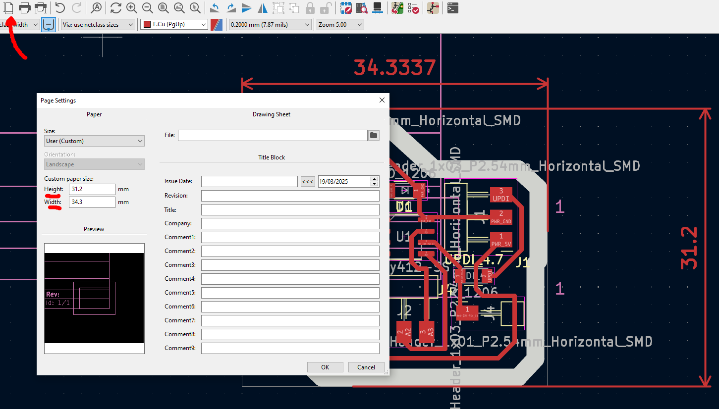
First, we will use software that requires SVG files for the cutting paths. So, to generate these files, it is necessary to export them from the software used to design the PCB, which in my case is KiCad (one SVG file for each layer). The method for generating SVG files in KiCad has changed in recent versions. In earlier versions, it was straightforward to select the option to export in that format. However, this option is no longer available in version 9. Therefore, I will outline the process I followed to generate the files.
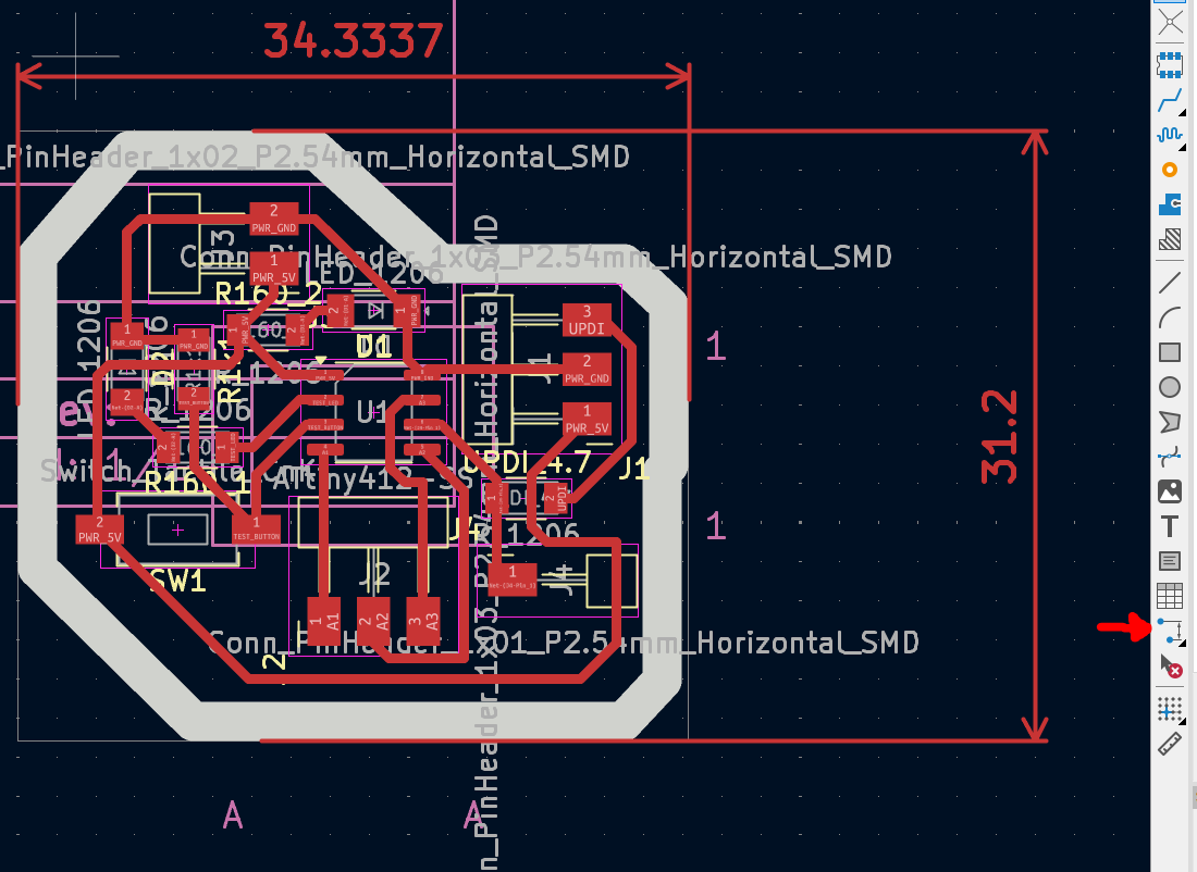
.PNG)
Figure 4: Generate SVG files from "Plot" (select only the necessary layers).
Some consideration from the previous ESP32 board (Week 6)...
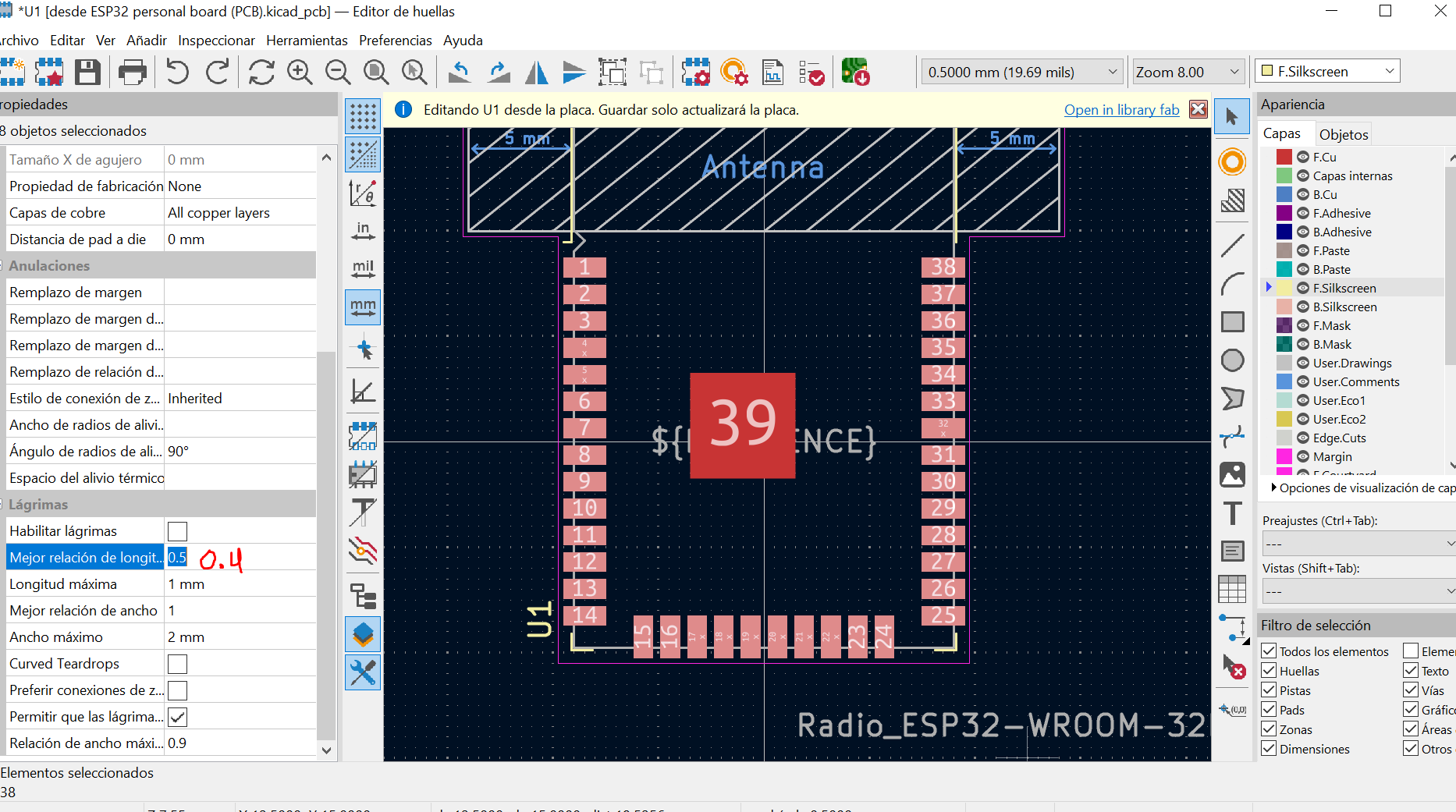
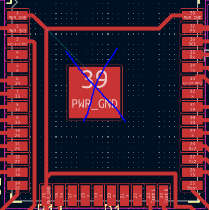
Once this is done, we enter the online software "Mods".
MODS is a browser-based, modular software platform designed for digital fabrication environments. It operates through a system of connectable nodes that take inputs (such as images or vector files) and generate machine instructions like G-code or RML for controlling CNC routers, laser cutters, milling machines, and more. Fortunately, MODS offers excellent support for the Roland SRM-20, which significantly simplifies PCB fabrication for my case.
Right-click and navigate to Programs, then select Open Program. Next, locate the section for the Roland SRM-20 mill and click on Mill 2D PCB to initiate the process. It should appear something like this on your screen.
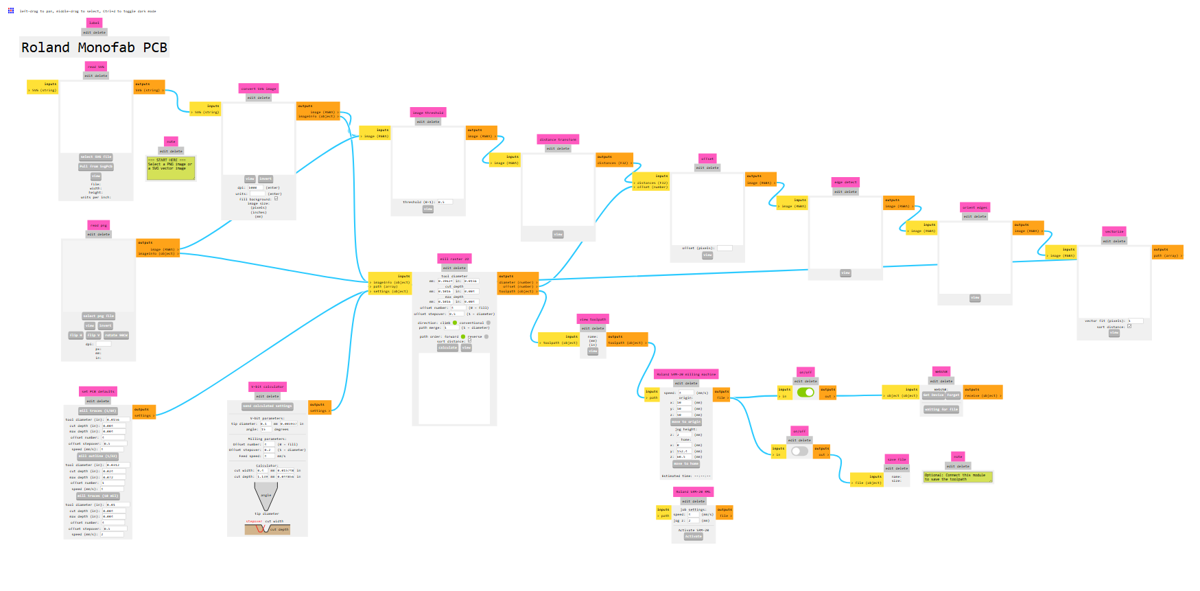
Figure 5: First look at "Mods" for the board.
Now, we need to load the file, select the tool (edit it if necessary), define the offset, the speed, and generate the file.
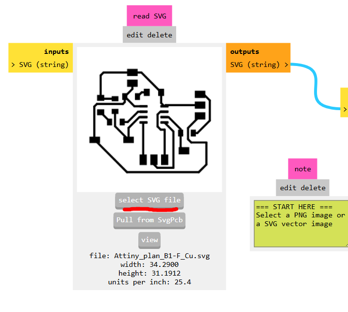
Figure 6: Loading the file.
For the engraving process, or more precisely, for tracing the PCB's paths, it is essential to invert the image. This is because the software relies on the file to define the cutting lines, and for the tracks, the goal is not to cut through them but to outline their boundaries for proper routing.
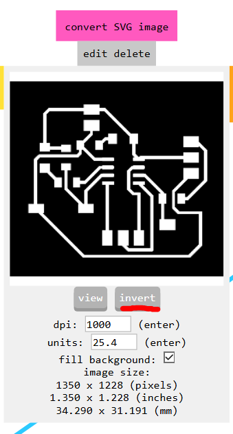
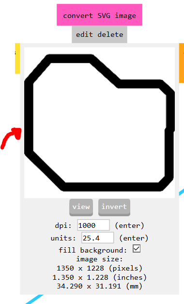
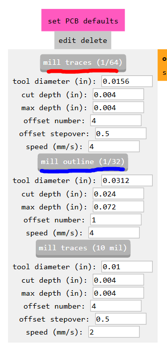
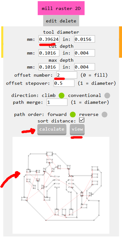
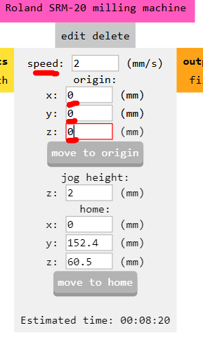
Figure 11: Defining the speed, the smaller the diameter, the slower the tool must go.
Trace Milling:
- Tool diameter: 0.4 mm
- Offset number: 2–4 (more offsets mean better isolation but longer machining time)
- Speed: 0.5–2 (depends on tool strength; fragile bits require slower speeds)
PCB Cutting:
- Tool diameter: 2 mm
- Offset number: 1
- Speed: 4
Before generating the file, it is recommended to at least visualize how the cutting lines are drawn to understand the CNC's operations. This step helps prevent wasting material or damaging the cutting tool. It is important to note that the SRM-20 can easily break its tools because of their small diameter.
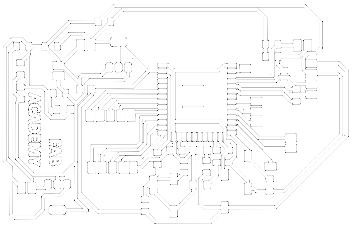
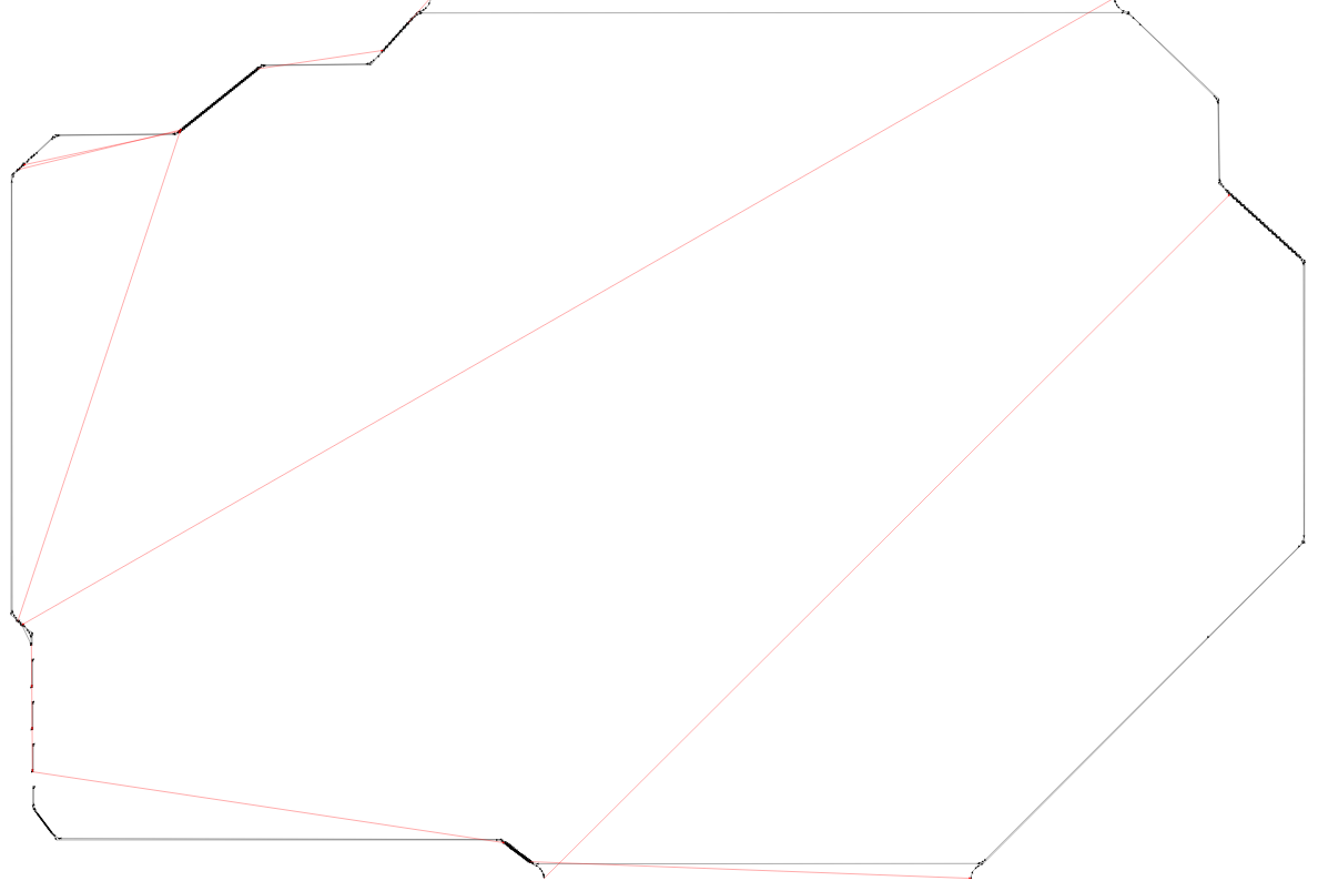
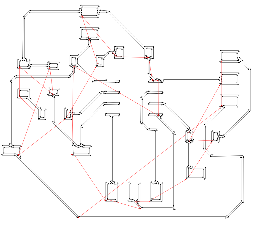
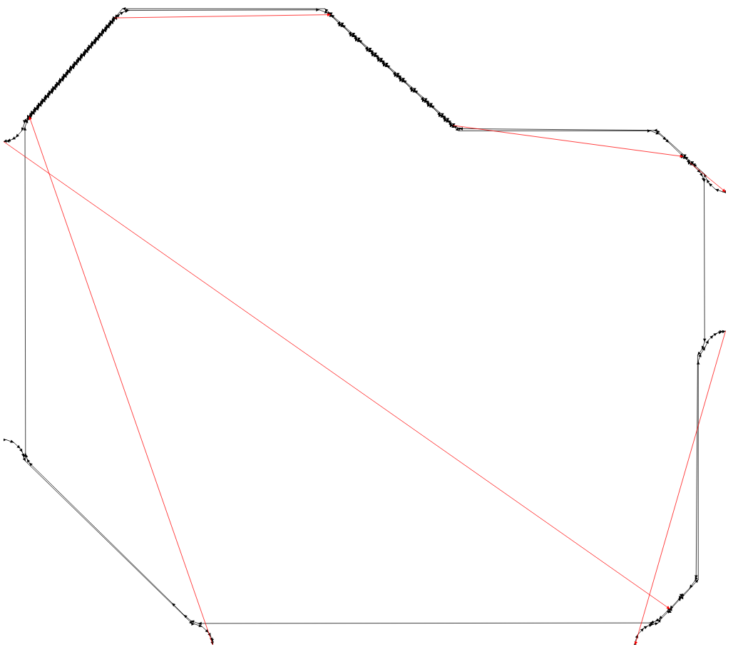
If everything seems correct, we can then activate the option to generate the file and recalculate to finalize the file generation.
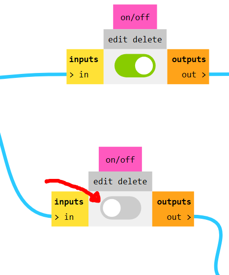
Figure 16: Activate file generator.
Board Preparation and Use of the SRM-20
First, ensure that the software is installed on your system. You can download it here, along with the necessary driver. If you encounter any issues during installation, you can always refer to the official Download Center for assistance.
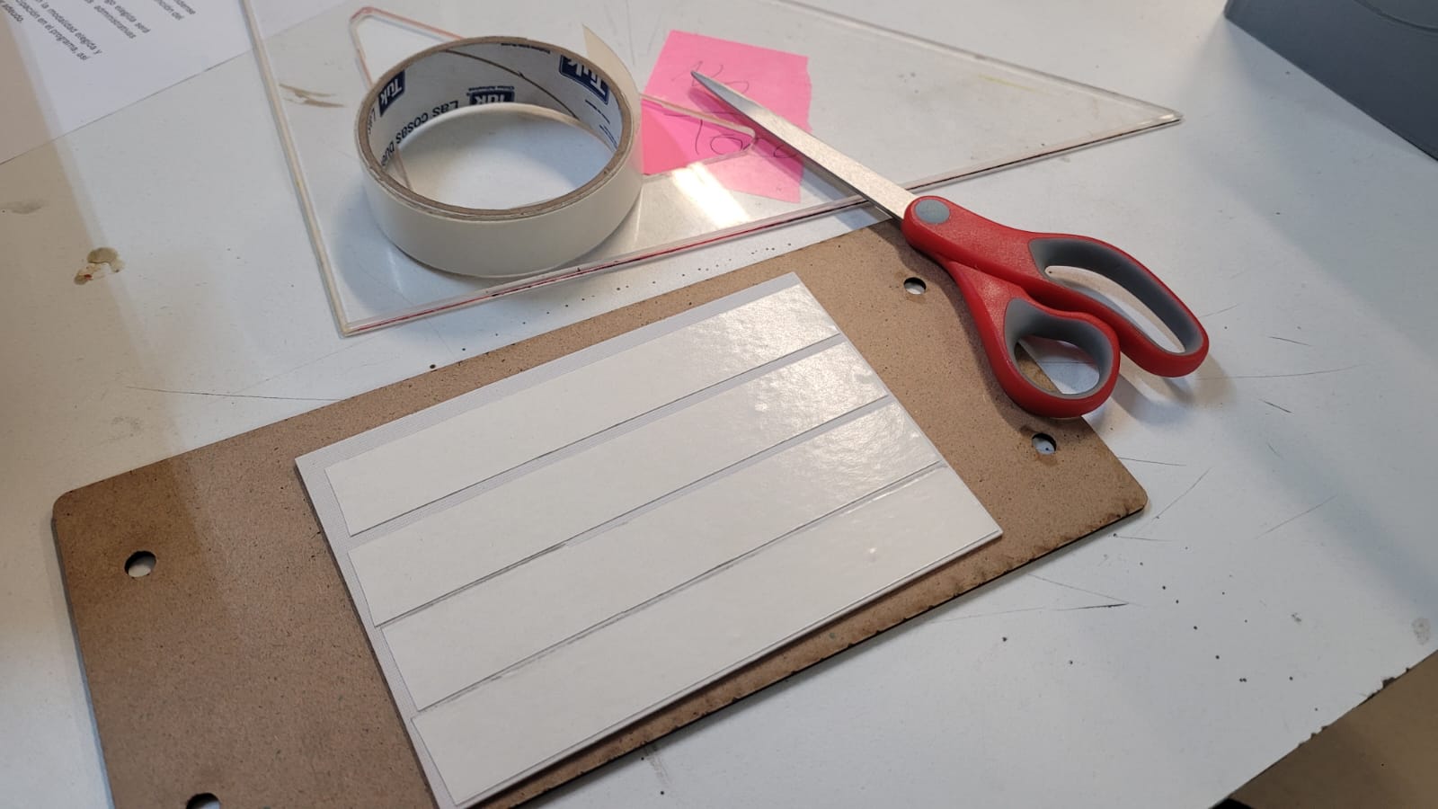
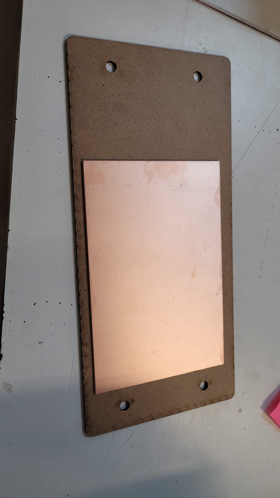
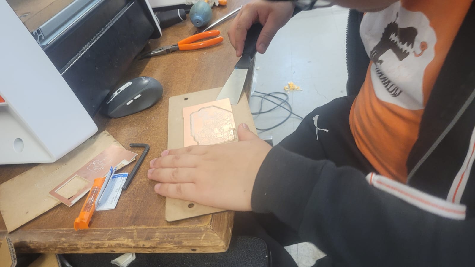
Before diving into the software, it is important to prepare the copper phenolic plate for cutting. This process is similar, though on a smaller scale, to the router. Therefore, the plate should be securely fixed in place, ideally positioned on a sacrificial bed to protect the surface beneath it. Lastly, a new origin point must be set for both cutting and engraving.
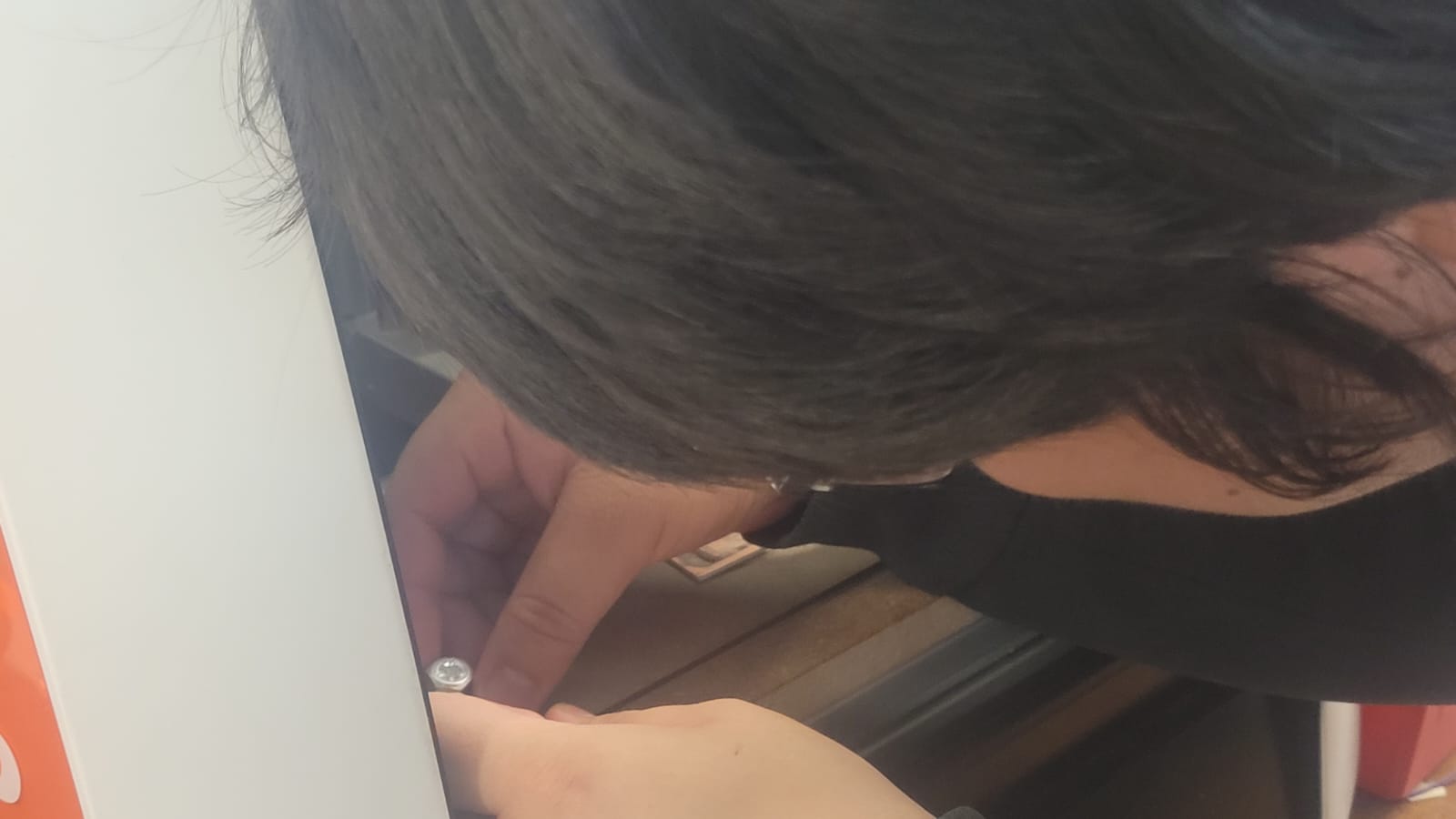
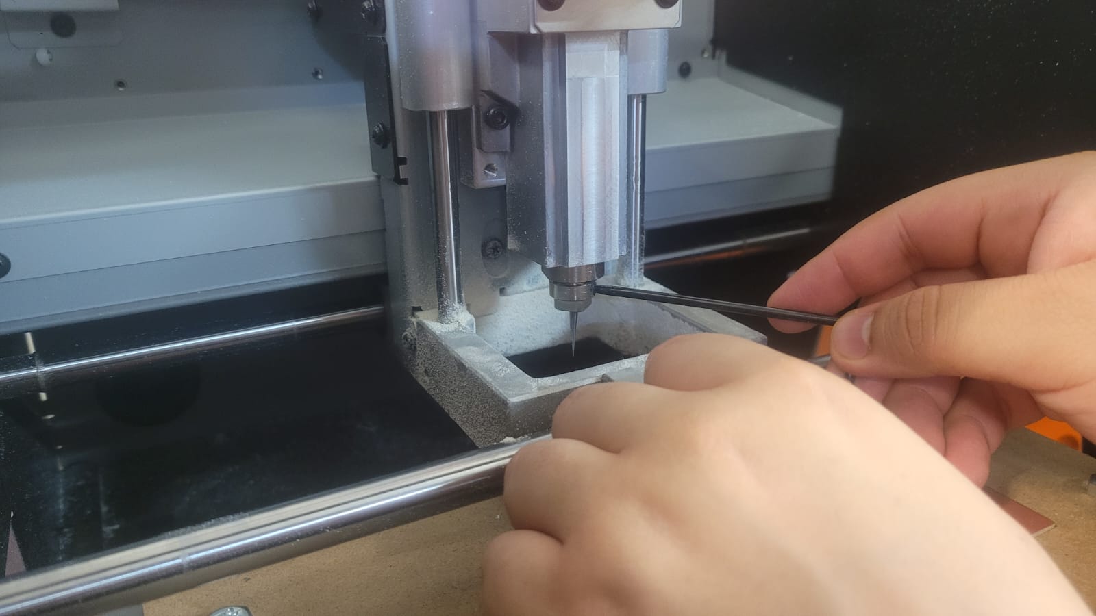
The software is quite intuitive to use. Upon opening, it provides a clear interface for controlling the CNC across all its axes, as well as the number of steps to be executed. At the bottom, you will find buttons to return to the factory-set origin of the machine, while the buttons for setting a new origin for the cut are located on the right side. In the lower-left corner, there are controls to manually turn the motor that rotates the cutting tool on or off (this can only be activated when the SRM-20 cover is closed, as a safety feature).
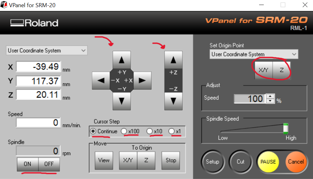
Figure 21: Vpanel interface.
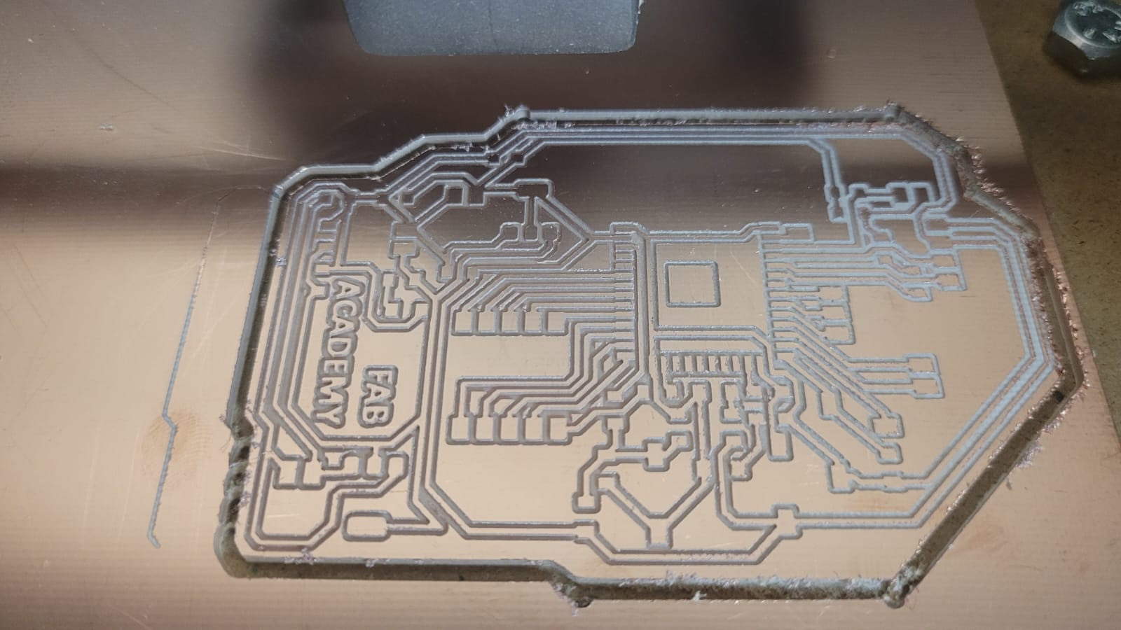
An essential step here is calibrating the Z-axis origin, which determines the depth of the tool's cut into the plate. If not calibrated correctly, the tool may either not cut or engrave deeply enough, or it may cut or engrave too much (a properly cut plate should have a clean white outline). To calibrate, gradually lower the tool until it contacts the plate. At this point, you will notice a change in the CNC’s sound. Using this as a reference, lower the Z-axis origin by a few thousandths (1 or 2) to ensure the tool cuts or engraves the plate properly.
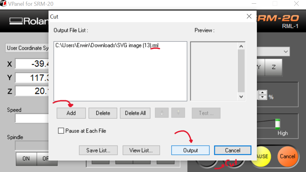
Once the Z-axis is calibrated, the next step is to define the origin in the X/Y axes. Then, load the ".rml" file (one per layer, as the engraving or cutting tool may differ between layers) and begin the CNC operation.
Soldering the board
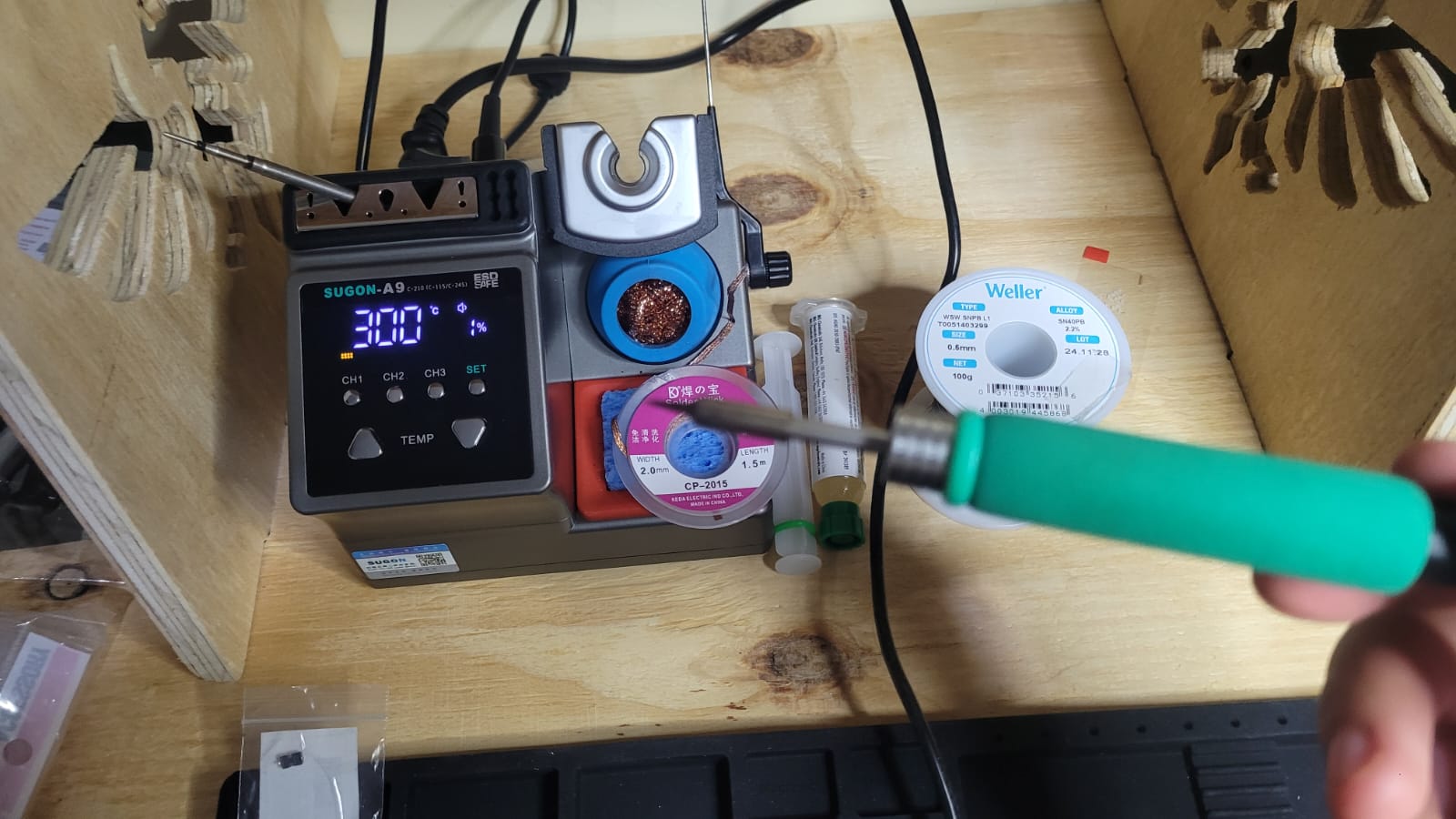
So far, we have only manufactured the board tracks; however, the next step is to solder the components. For the soldering technique, I recommend watching the following video, which covers the essential concepts for proper soldering. In my case, I used only a soldering iron, solder, and some flux. I chose not to use a heat gun or soldering paste, as the board lacks a coating that would facilitate soldering with these tools. Using them in this scenario could result in over-soldering the components.
Regarding the values of the capacitors and resistors, most were derived from the Espressif design. However, for the resistors associated with the LED and button, I calculated their values using Ohm's law (V=IR).
For the buttons, there is little concern about precise resistor values. Since they are pull-up or pull-down resistors, it is not critical to have an exact value. However, it is important that the resistance is high enough to function correctly as a pull-up or pull-down resistor. In this case, I chose a value of 1k ohms.
For the LEDs, I applied Ohm's law to ensure they would glow brightly. Given the nominal voltage of the red LEDs (approximately 1.9V), the supply voltage, and a current of 20mA for optimal brightness, I calculated resistor values of 155 ohms for 5V and 70 ohms for 3.3V. To ensure the resistors are within a safe range, I selected 160 ohms for the 5V supply and 75 ohms for the 3.3V supply.
Materials List:
Esp32 Board
| Quantity | Component |
|---|---|
| 1 | ESP32 WROOM 32E |
| 2 | 4.7k Resistor (1206) |
| 4 | 0 Resistor (1206) |
| 2 | 75 Resistor (1206) |
| 1 | 1k Resistor (1206) |
| 1 | 160 Resistor |
| 3 | 1206_Tactile_Buttton |
| 3 | 1206_Led |
| 4 | 47uF Capacitor (1206) |
| 4 | 22uF Capacitor (1206) |
| 1 | AMS1117-3.3 |
| 1 | AMS1117-5 |
| 28 | Male pins |
Attiny412 Board
| Quantity | Component |
|---|---|
| 1 | Attiny412 |
| 1 | 4.7k Resistor (1206) |
| 1 | 1k Resistor (1206) |
| 2 | 160 Resistor (1206) |
| 1 | 1206_Tactile_Buttton |
| 2 | 1206_Led |
| 8 | Male pins |
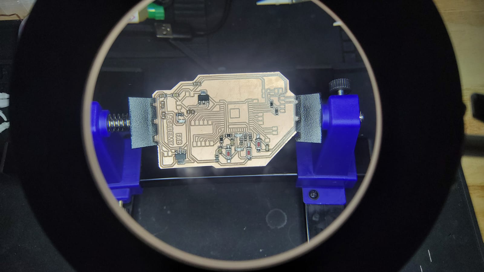
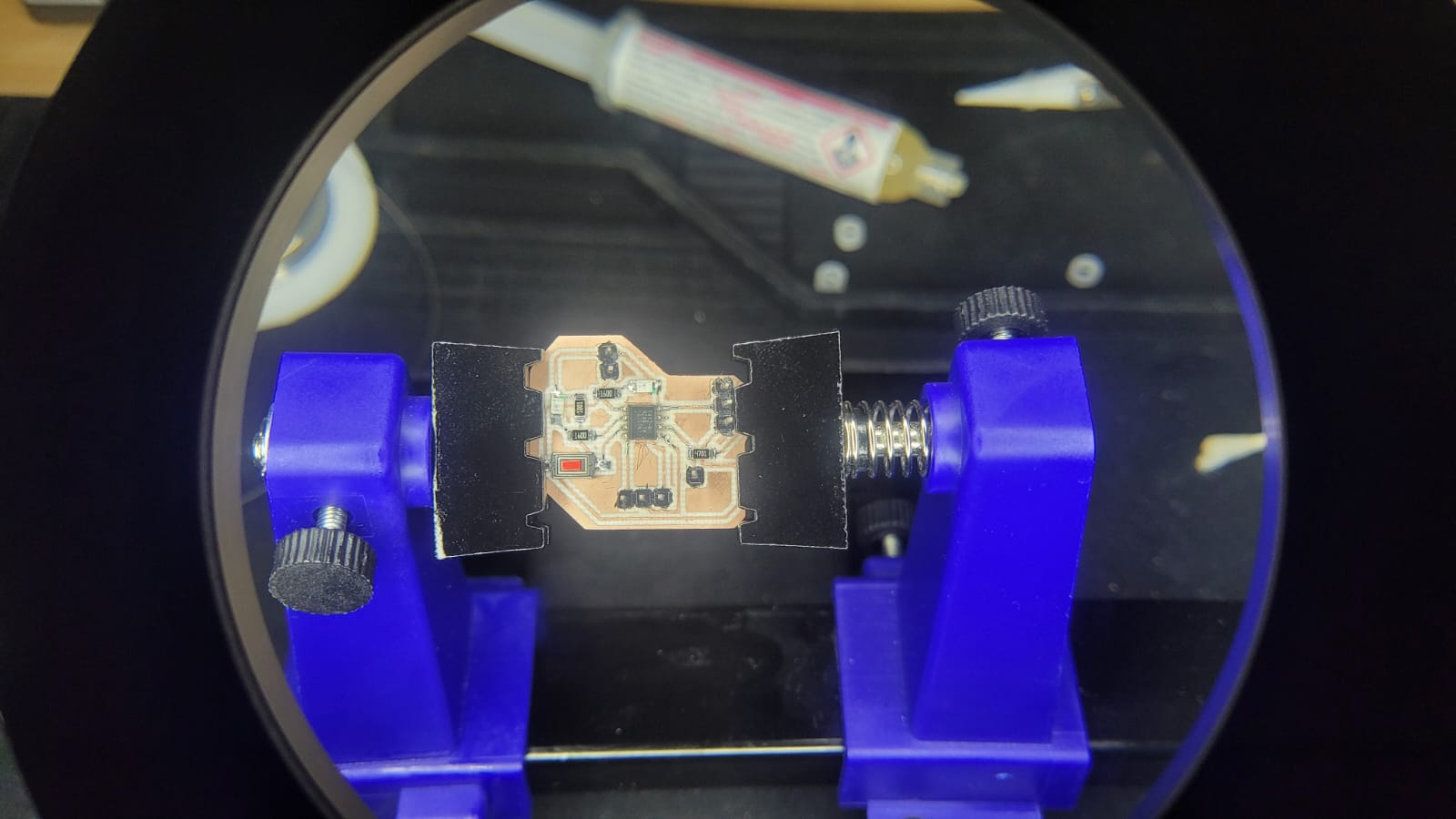
Test run
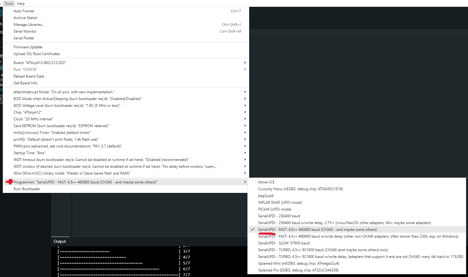
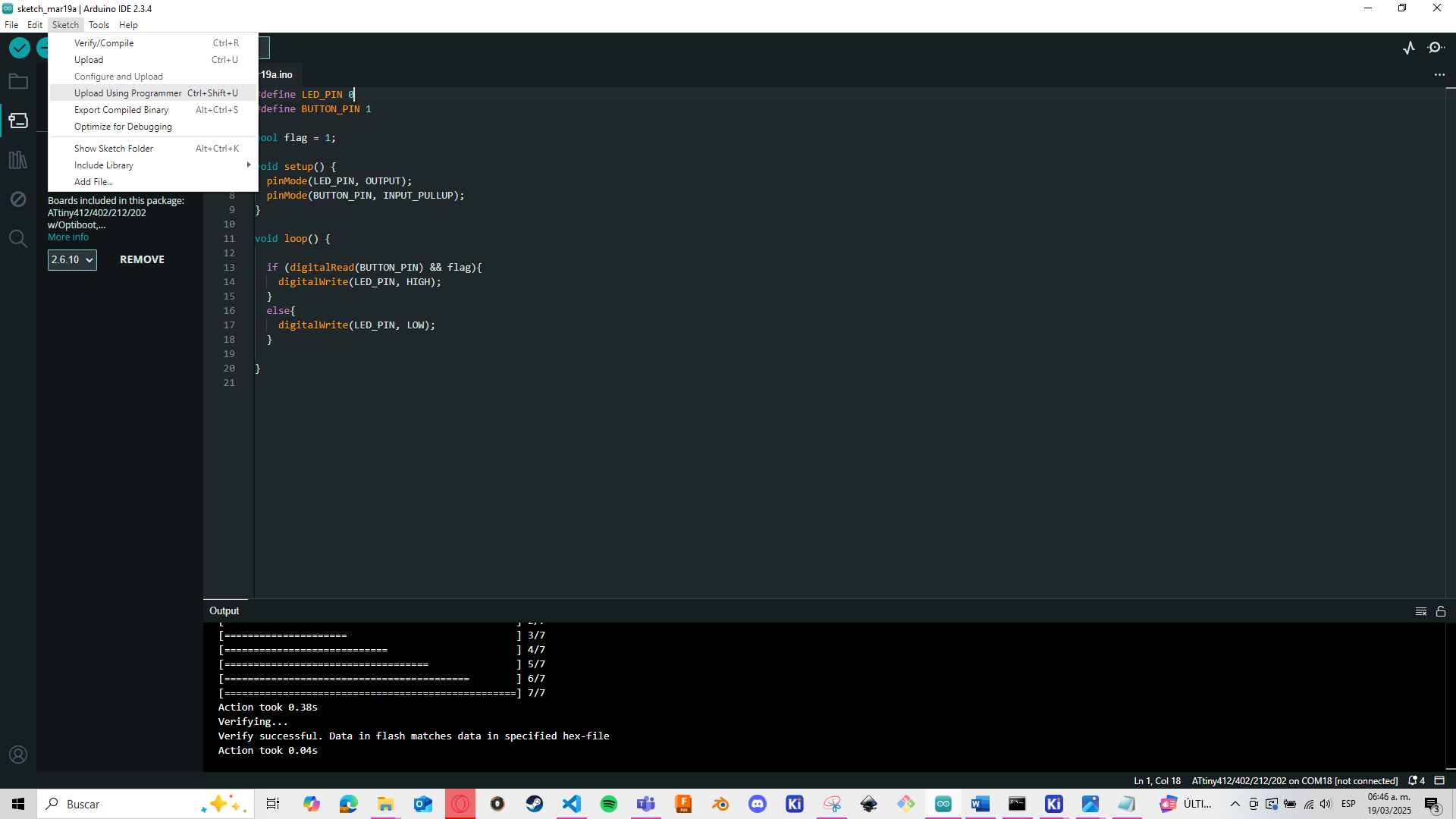
I will test the ESP32 board once the microcontroller arrives and is soldered. In the meantime, to program the Attiny412, I used a development board manufactured at Fablab called Quentorres. I will briefly explain how to program the Attiny412 using UPDI with this board and the Arduino IDE.
To proceed, it is necessary to add the following preference in the IDE: https://drazzy.com/package_drazzy_com_index.json
Furthermore, for this to work, a 4.7k ohm resistor must be placed in parallel with the RX and TX pins of the board. This resistor is already included in my Attiny board design. Therefore, simply follow these steps:
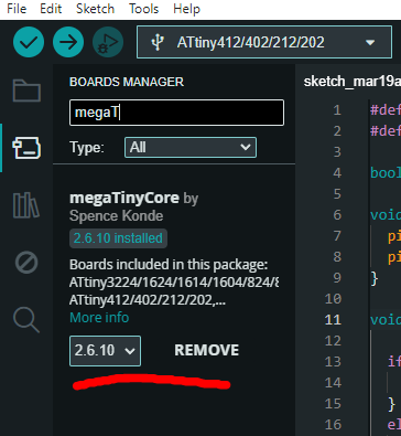
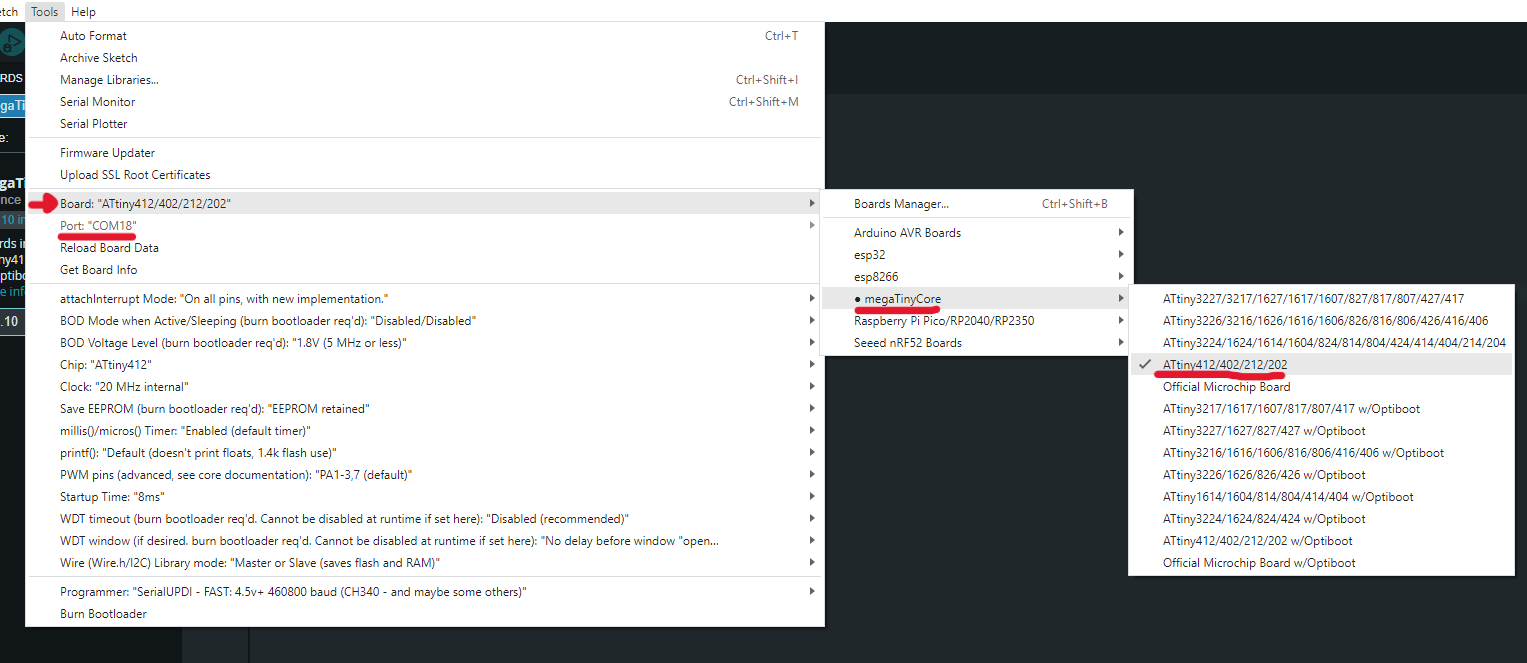
Code
  #define LED_PIN 0
  #define BUTTON_PIN 1

  bool flag = 1;

  void setup() {
    pinMode(LED_PIN, OUTPUT);
    pinMode(BUTTON_PIN, INPUT_PULLUP);
  }

  void loop() {
    if (digitalRead(BUTTON_PIN) && flag){
      digitalWrite(LED_PIN, HIGH);
    }
    else{
      digitalWrite(LED_PIN, LOW);
    }
  }
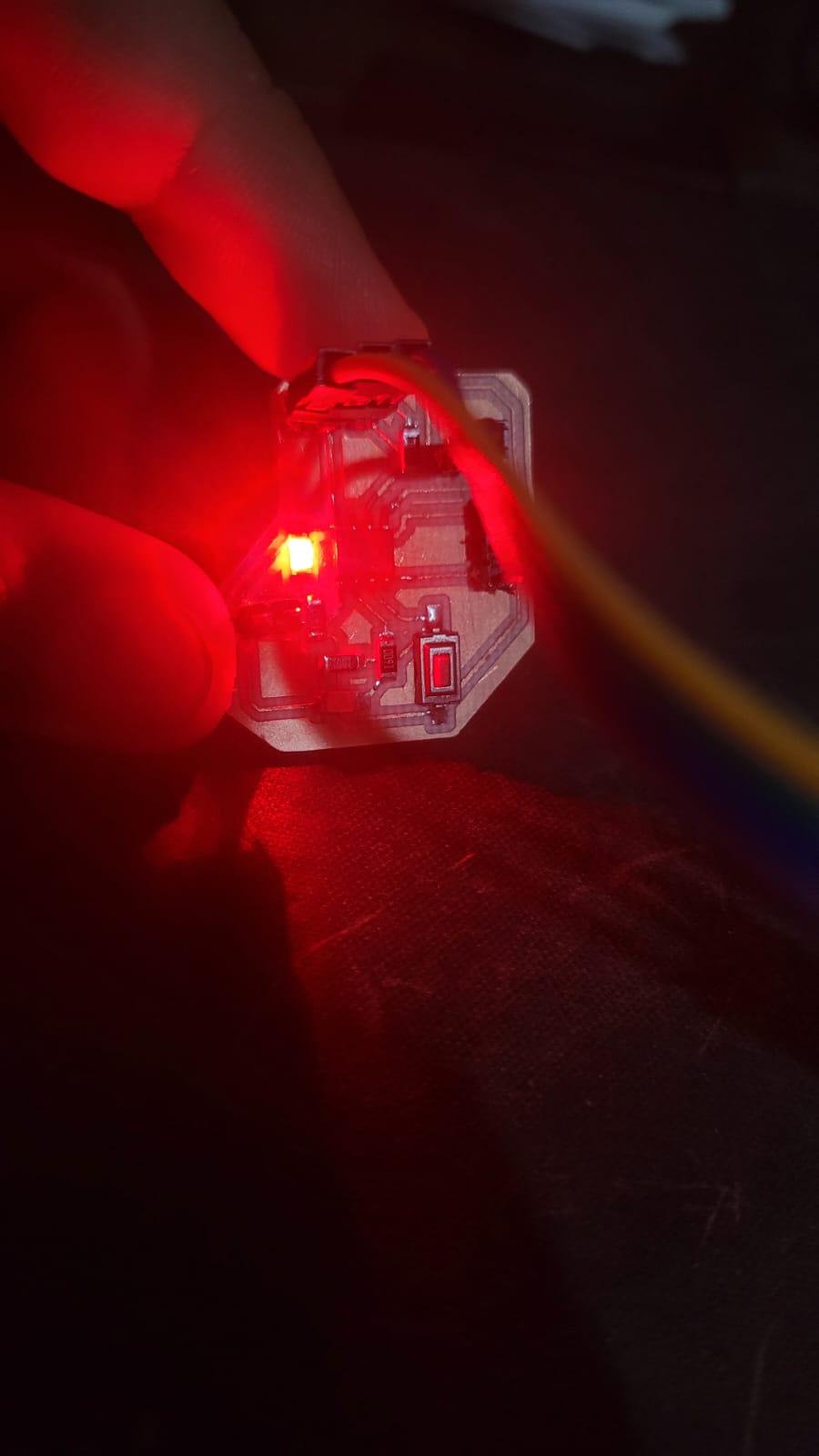
If everything went correctly, we can finally conclude that the board is ready to use.
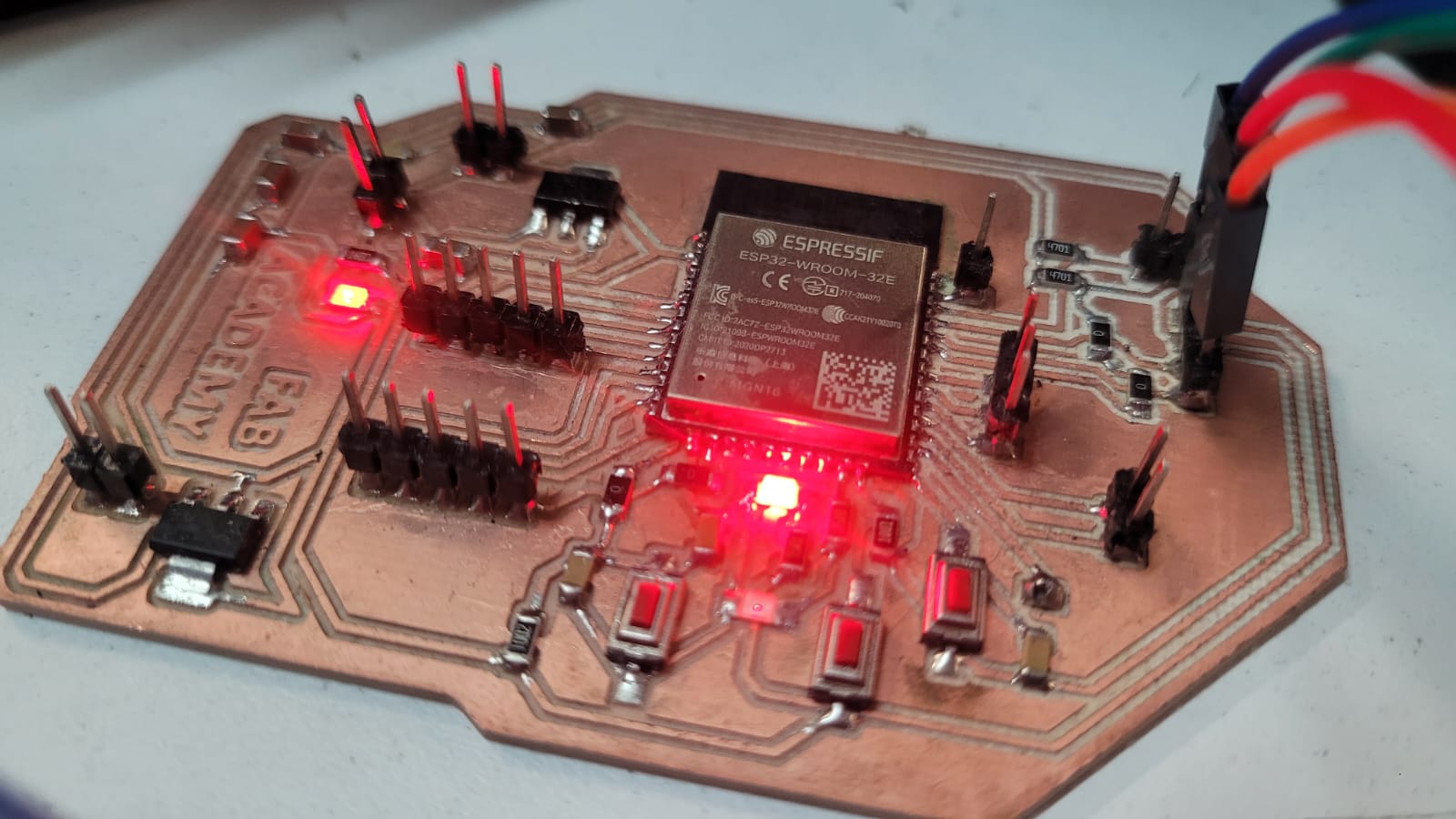
UPDATE! (The ESP32 chip arrive!)
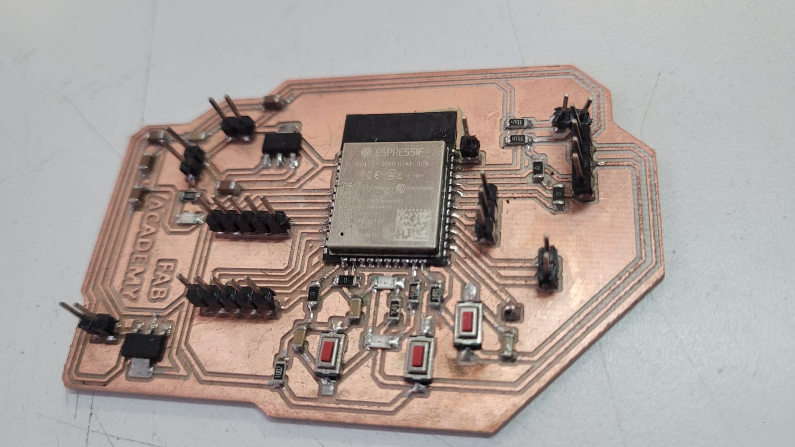
Programming the ESP32 via UART
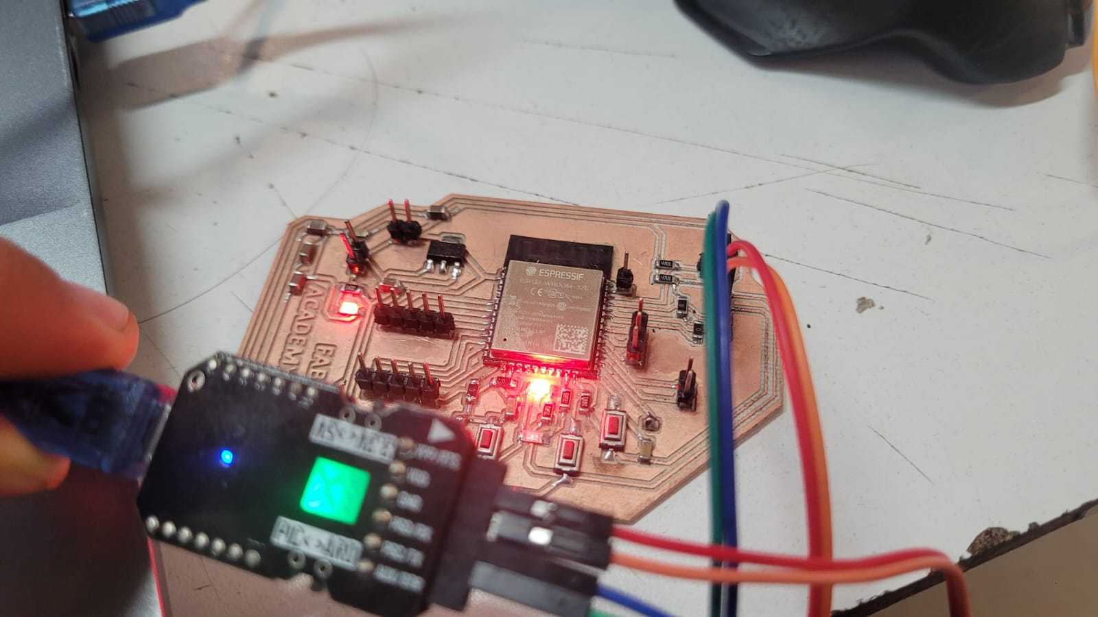
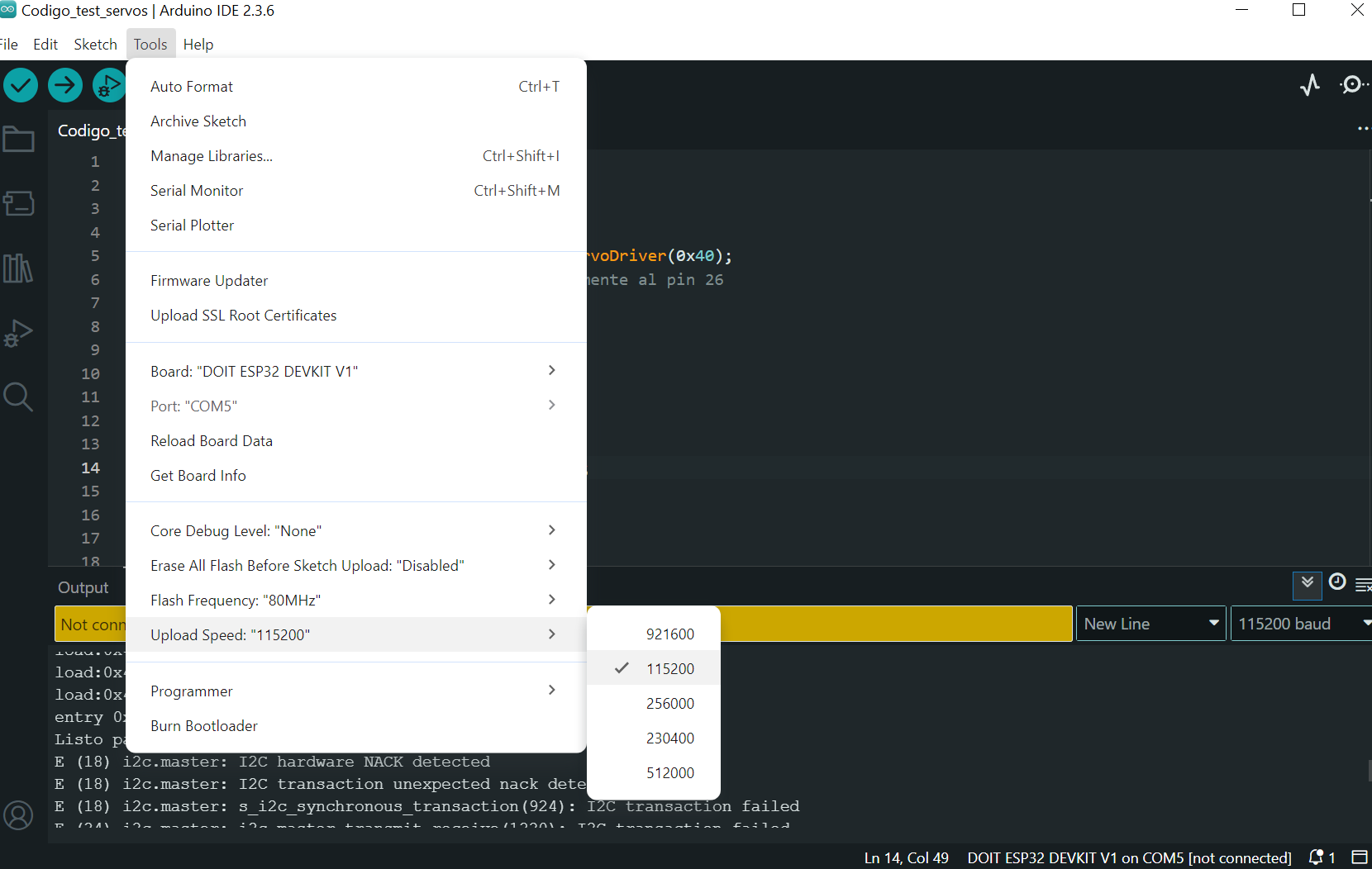
The ESP32 uses the Espressif Serial Bootloader Protocol, which is embedded in the chip’s ROM, to allow firmware uploading through the TX and RX pins. To enter bootloader mode, GPIO0 must be pulled LOW while resetting the chip via the EN/RESET pin. Once in boot mode, the firmware can be flashed using tools like esptool.py or platforms like Arduino IDE or PlatformIO, typically at 115200 baud or higher.
In my case, I opted to use an external programmer, the Microside XCU, which acts as a USB-to-UART bridge. This simplifies the connection to TX, RX, EN, and GPIO0, allowing me to flash firmware without pressing any buttons manually. For reference, the full documentation is available here.
Considering all these advantages, I chose to use this programmer for my ESP32 projects.
  #define BUTTON_PIN 2
  #define LED_PIN    15

  void setup() {
    pinMode(BUTTON_PIN, INPUT_PULLUP);
    pinMode(LED_PIN, OUTPUT);
    digitalWrite(LED_PIN, LOW);
  }

  void loop() {
    if (digitalRead(BUTTON_PIN)) {
      digitalWrite(LED_PIN, HIGH);
    } else {
      digitalWrite(LED_PIN, LOW);
    }
  }
LEARNINGS
This week, in addition to learning how to operate the SRM-20, I was able to significantly improve my SMD soldering skills. Also, after gaining experience with the router, I found the SRM-20 easier to use, as both machines share similar calibration and operational processes (although one is larger and the other is smaller).
The ESP32 situation also led me to realize that I’ve developed a knack for quickly designing PCBs from scratch. That said, I know my success in manufacturing the PCB wouldn't have been possible without the support of my colleagues and friends at Fab. While I faced many challenges along the way, they provided invaluable advice, and together, we learned a number of techniques that helped us master PCB fabrication, especially when working with the SRM-20.
