Summary
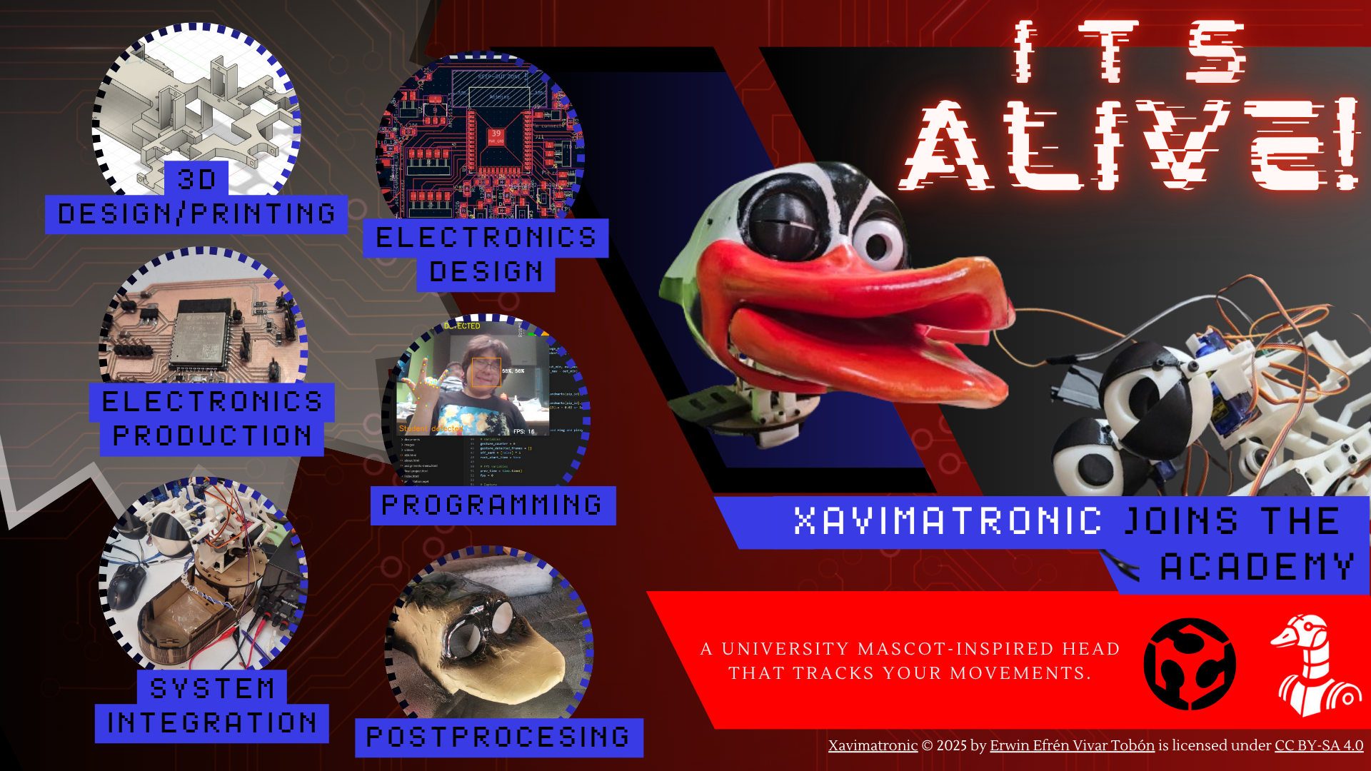
This project consists of creating an animatronic head that smoothly tracks human movements using MediaPipe for real-time face recognition. The system integrates various mechanical subsystems such as the eyes, eyelids, neck, and beak, with movements coordinated to engage viewers in an interactive and lifelike manner.
The mechanical components are primarily 3D printed using PLA and mounted on a 2.5 mm MDF base. These components include servos that control the movement mechanisms of the eyes, eyelids, neck, and beak.
Initially it was planned to incorporate Two 1.28” round TFT displays (GC9A01) to enhance the visual appeal of the animatronic, however, due to the length of the cables and the noise they caused for SPI communication, the idea was discarded.
The project utilizes a custom ESP32 PCB to ensure smooth communication between all components. The electronics are designed with a PCA9685 driver module, which efficiently handles the control of multiple servos.
The design process involves the use of both 2D and 3D CAD tools, such as Fusion 360 and Blender, to create and simulate the mechanical subsystems. This design process has been crucial for achieving precision and functionality.
Additionally, AI-based vision systems are incorporated into the animatronic, powered by a Raspberry Pi 5. This AI integration enhances the animatronic’s ability to track and respond to real-time movements and gestures.
The main goal of the project was to create a fully functional animatronic head that autonomously responds to human movements and gestures. However, the current version is focused primarily on achieving a visually appealing and interactive head mechanism.
All materials for the project were sourced from local FabLab resources or my own wallet, with electronic components purchased online. Each system, from the mechanical design to the electronics, was fabricated and assembled with meticulous care to ensure proper integration of both hardware and software components.
| Category | Item | Price |
|---|---|---|
| Mechanical Materials | PLA Filament (1 kg spool) | $23.63 - Based on PrusaSlicer |
| Mechanical Materials | MDF Sheets, 2.5 mm thickness | - |
| Mechanical Materials | Screws M3 (various lengths: 25 mm, 12 mm, 10 mm, 8 mm, 4 mm) | AliExpress |
| Mechanical Materials | Screws M2 (lengths: 5 mm, 8 mm) | - |
| Mechanical Materials | Screws M5 (length: 25 mm) | - |
| Mechanical Materials | 625ZZ Bearings - 3 units | AliExpress - $4.7 |
| Electronic Components | 1.28” Round TFT Displays (GC9A01) - 2 units | AliExpress - $6.22 |
| Electronic Components | PCA9685 PWM Servo Driver Module - 1 unit | AliExpress - $3.52 |
| Electronic Components | Micro Servos (SG90/MG90S) - 6 units | AliExpress - $26.32 |
| Electronic Components | High-Torque Servos (MG996R) - 2 units | AliExpress - $24.51 |
| Electronic Components | High-Torque Servos (TD-8120MG) - 3 units | AliExpress - $21.06 |
| Additional Hardware | Raspberry Pi 5 - 1 unit | AliExpress - $165.24 |
| Additional Hardware | Raspberry Pi Camera Module v2 - 1 unit | AliExpress - $15.57 |
| Additional Hardware | LiPo Battery 11.1 V, 5500 mAh - 1 unit | Amazon Mexico - $61.40 |
| Electronic Components | ESP32 WROOM 32E - 1 unit | Digikey - $5.38 |
| Electronic Components | 4.7k Resistor (1206) - 2 units | - |
| Electronic Components | 0 Resistor (1206) - 4 units | - |
| Electronic Components | 75 Resistor (1206) - 2 units | - |
| Electronic Components | 1k Resistor (1206) - 1 unit | - |
| Electronic Components | 160 Resistor - 1 unit | - |
| Electronic Components | 1206 Tactile Button - 3 units | - |
| Electronic Components | 1206 LED - 3 units | - |
| Electronic Components | 47uF Capacitor (1206) - 4 units | - |
| Electronic Components | 22uF Capacitor (1206) - 4 units | - |
| Electronic Components | AMS1117-3.3 Voltage Regulator - 1 unit | Digikey - $0.27 |
| Electronic Components | AMS1117-5 Voltage Regulator - 1 unit | Digikey - $0.12 |
| Electronic Components | Male Pins - 28 units | - |
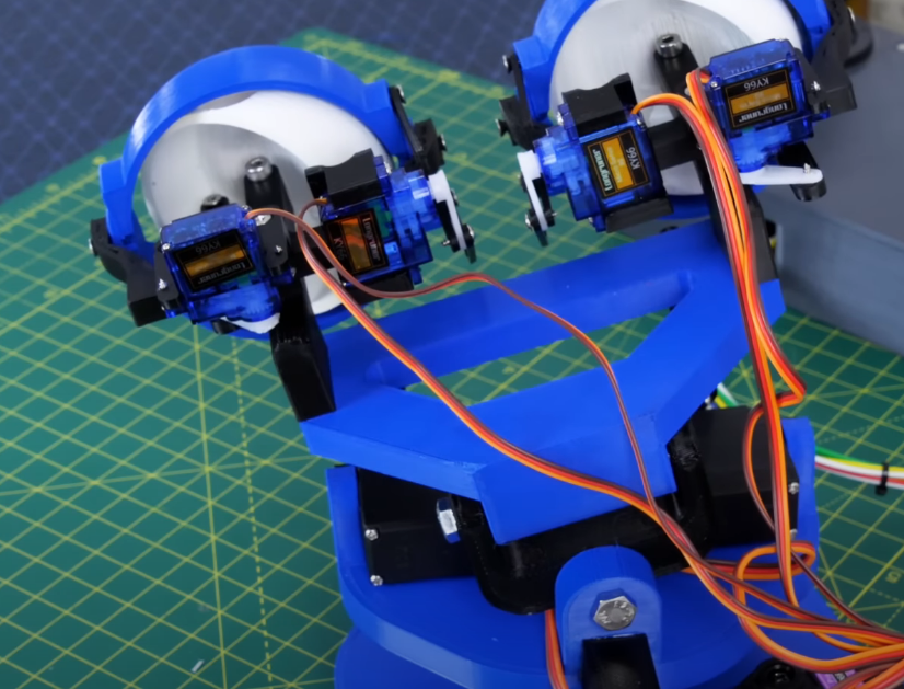
References and design, the eyes!
New Sketches!
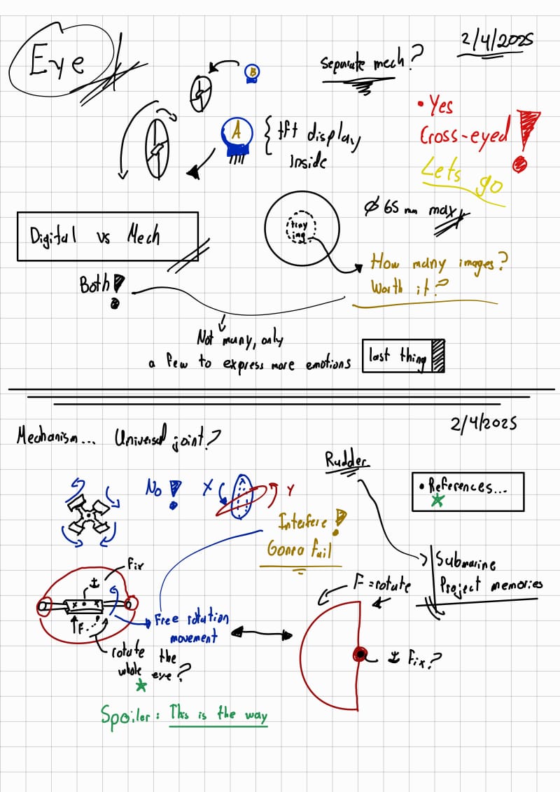
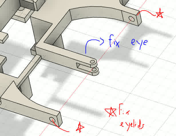
Eye mechanism and notes
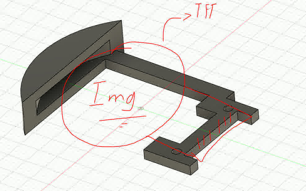
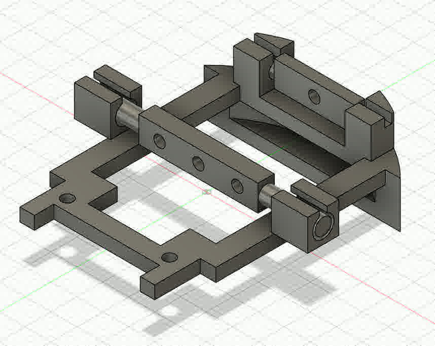
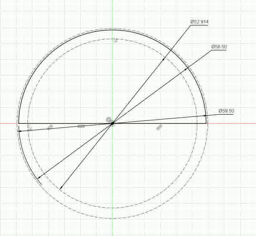
The main idea is that by means of pressfit I can “put the eye control and the TFT” inside another piece that serves as the eyeball.
Main idea to incorporate the eye rudder to serve as a support for the tft display too2_compressed
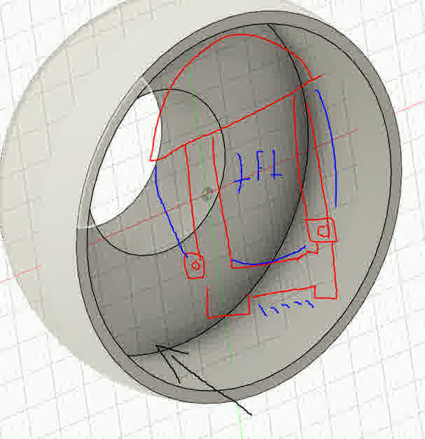
Adapter for uniform pressfit
Final idea
2_compressed.jpg)
Main idea of the rudder control (Free mobility)
I printed the components using PLA with 15% infill, as the parts didn’t require high strength.
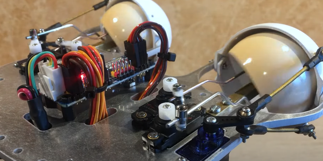
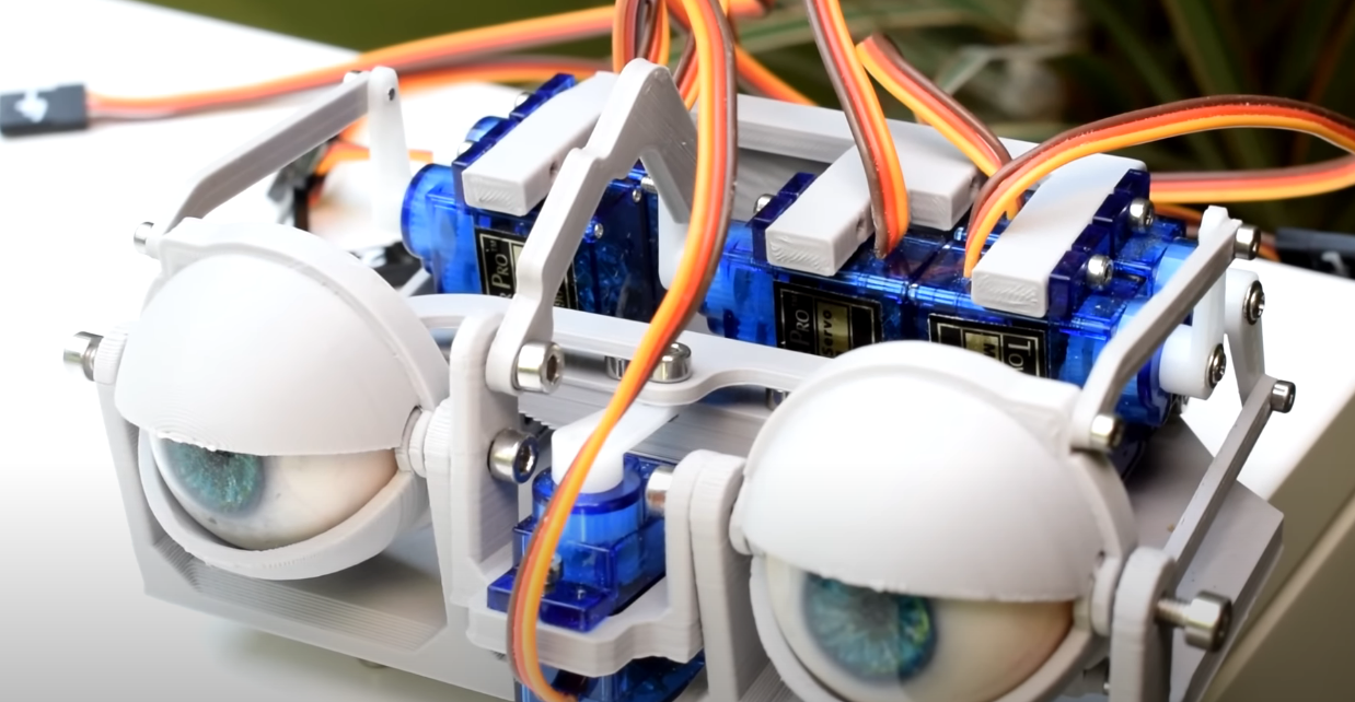
The eyeslids!
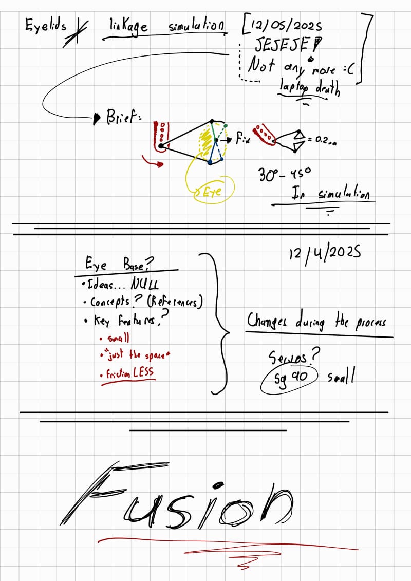
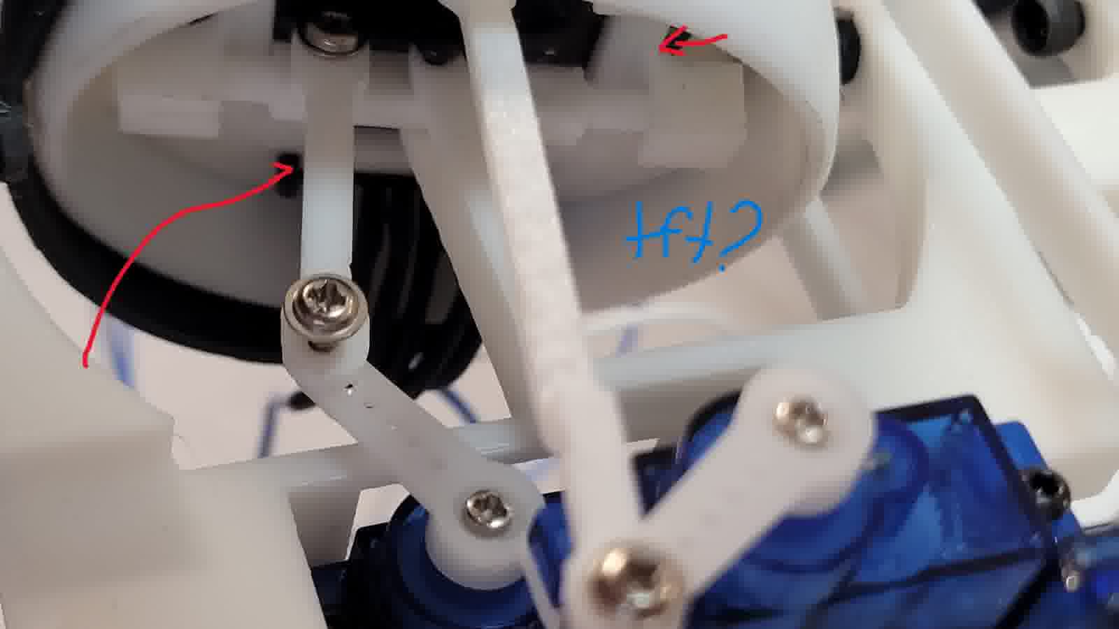
For eyelid actuation, I wanted a minimal energy footprint. Some designs use two servos per eye, while others control a single large eyelid. I opted for a single-servo linkage mechanism that could independently move both eyelids. I used Linkage software to simulate and measure the geometry needed. I'll run the simulation again... That's what I get for not saving it in the cloud (spolier).
New Sketches!
Eyelids sketch
Adapter for uniform pressfit
Main idea for the eyelids
Mirror replication
Servo base?
Assembling the servos proved tricky. I didn’t start with a fully planned design—instead, I adapted and iterated. The result was somewhat chaotic, but it allowed me to accommodate servo conflicts and placement issues in real time. The base for the servos came together organically through testing and adjustment.
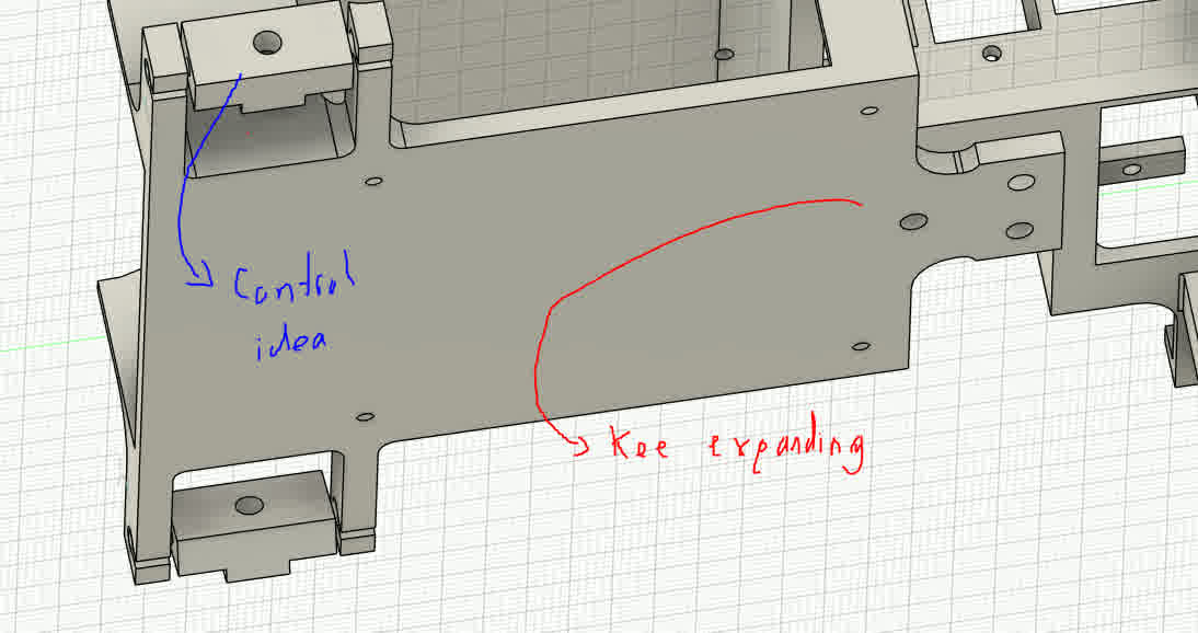
Always while designing my mind was thinking beyond and I was already thinking, what's next? So I had already estimated a moderate amount of servo motors. So, controlling them all from a single microcontroller would be impractical. The PWM generation and interrupts would overwhelm most microcontrollers. Therefore, I integrated a PCA9685 servo controller to offload the processing and ensure reliable timing.
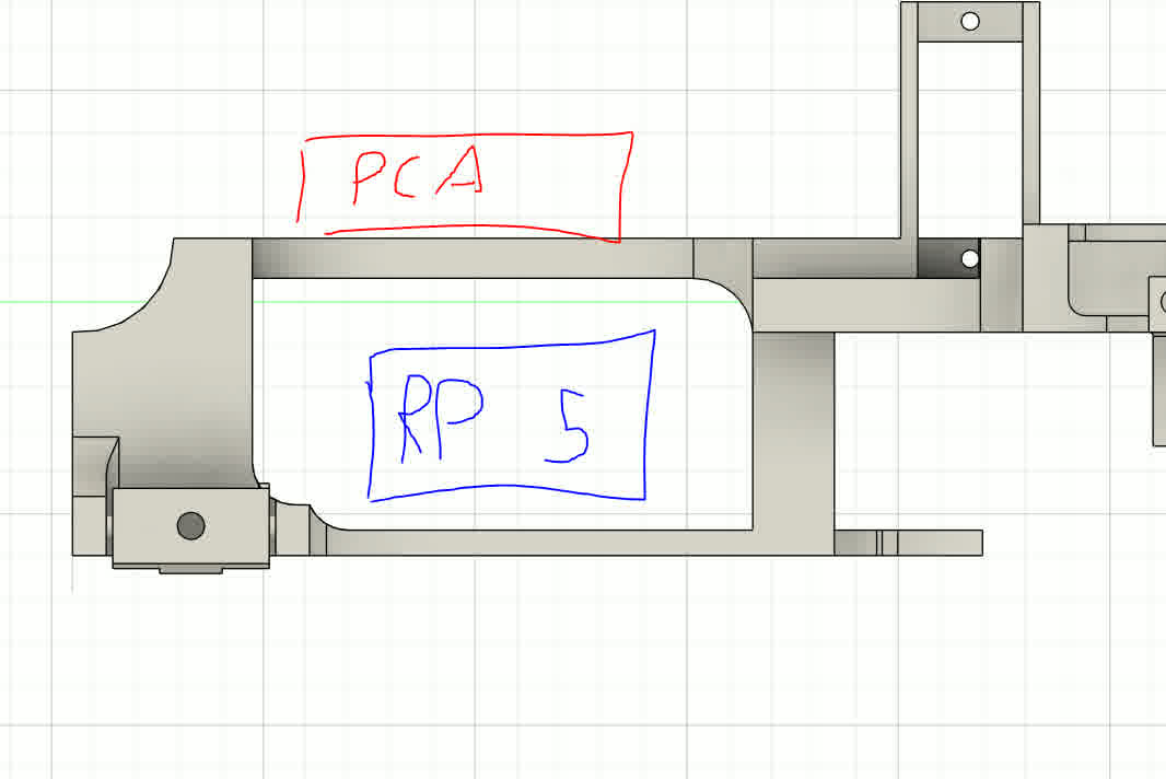
This led to another idea: since a head needs a brain, why not embed the “brain” within the head itself? My servo controller became the neural hub. For eye tracking and reactive motion, I wanted to implement AI-based recognition via camera input. I previously worked with MediaPipe to animate tentacles in another animatronic project, and I considered using it again. However, real-time AI processing requires significant computational resources.
Even lightweight AI models, like those trained with Edge Impulse, proved too demanding for a microcontroller. I didn’t want the animatronic tethered to my PC, so I integrated a Raspberry Pi 5 into the head as a dedicated onboard processor. This allows me to use Bluetooth or Wi-Fi to communicate with the system locally. I designed a dedicated mounting area for the Pi within the eye mechanism to ensure compact integration.
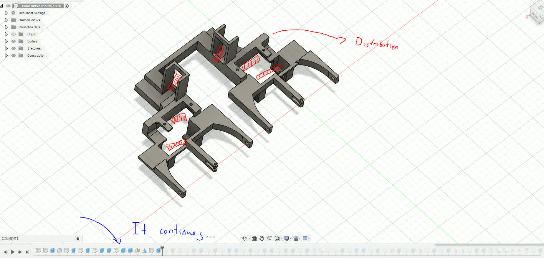
Distribution and chaotic timeline.
Electronic brain control consideration.
References and design, the neck!
New Sketches!
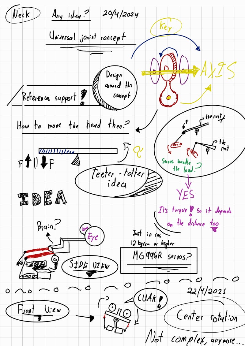
Neck sketch
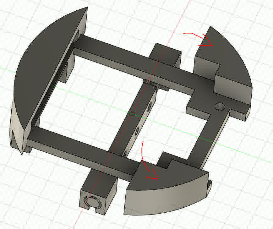
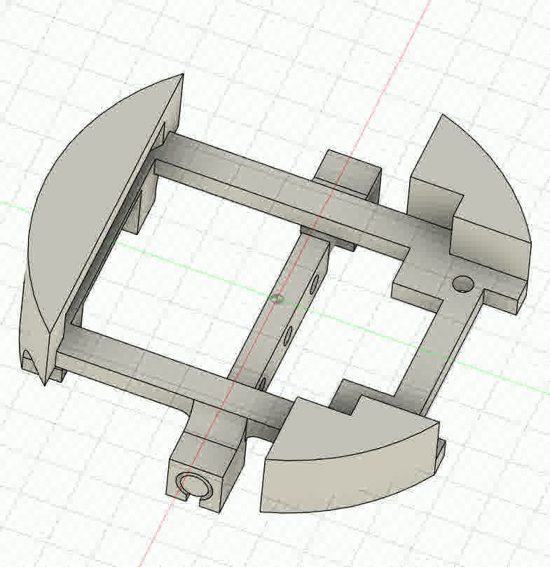
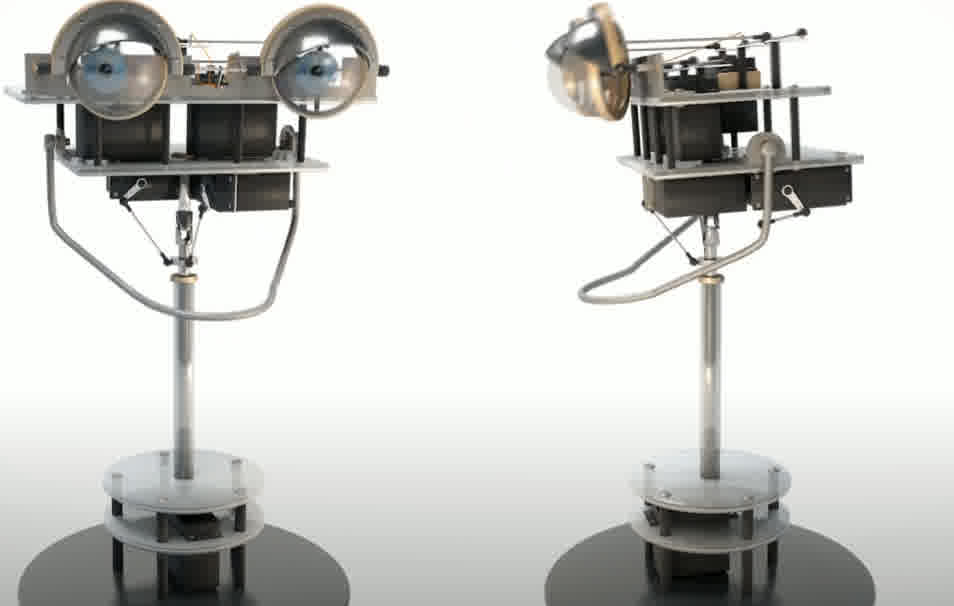
Next came the neck. I needed a robust, three-degree-of-freedom system capable of supporting the weight of the entire head. To achieve smooth motion, I used bearings to reduce friction. I custom-designed all parts in Fusion 360, building the mechanism to withstand up to 10 kg based on simulation data. All parts were assembled in a single Fusion file for simplicity.
Some info of the neck
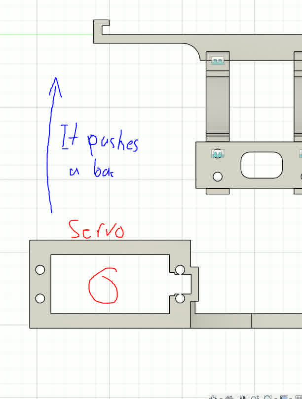
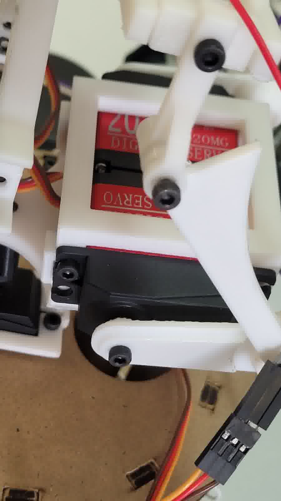
Servo actuator
Initially, I planned to place the rotational servo at the edge of the base for better torque leverage. However, this significantly increased the overall footprint of the head. Instead, I embedded the servo directly beneath the neck, creating a more compact and balanced design. I printed this structure with 40% infill to support the added weight.
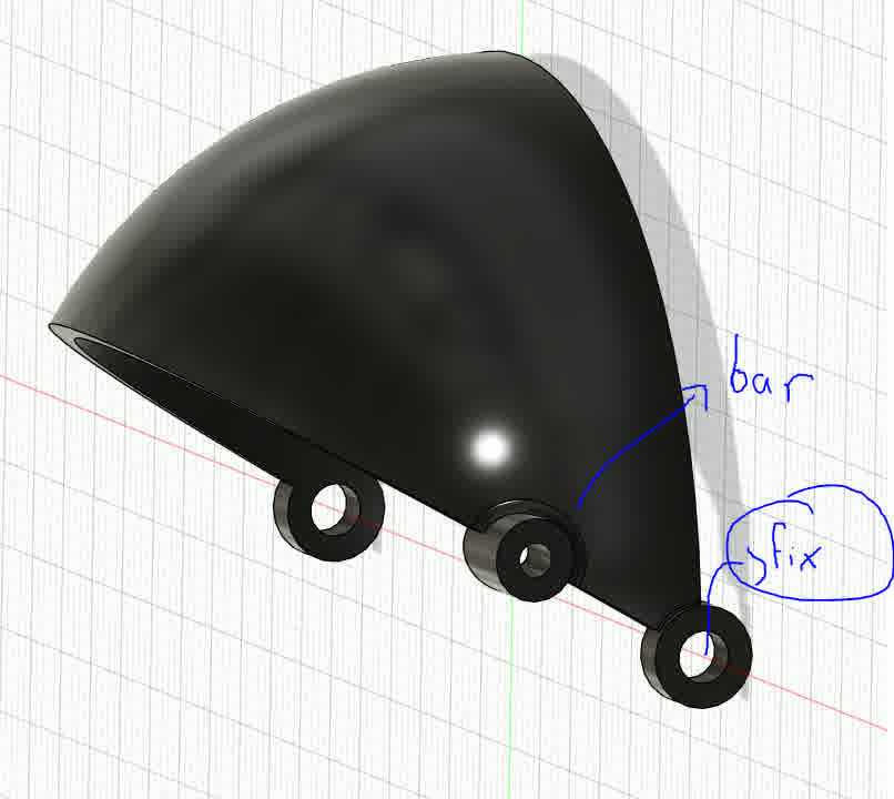
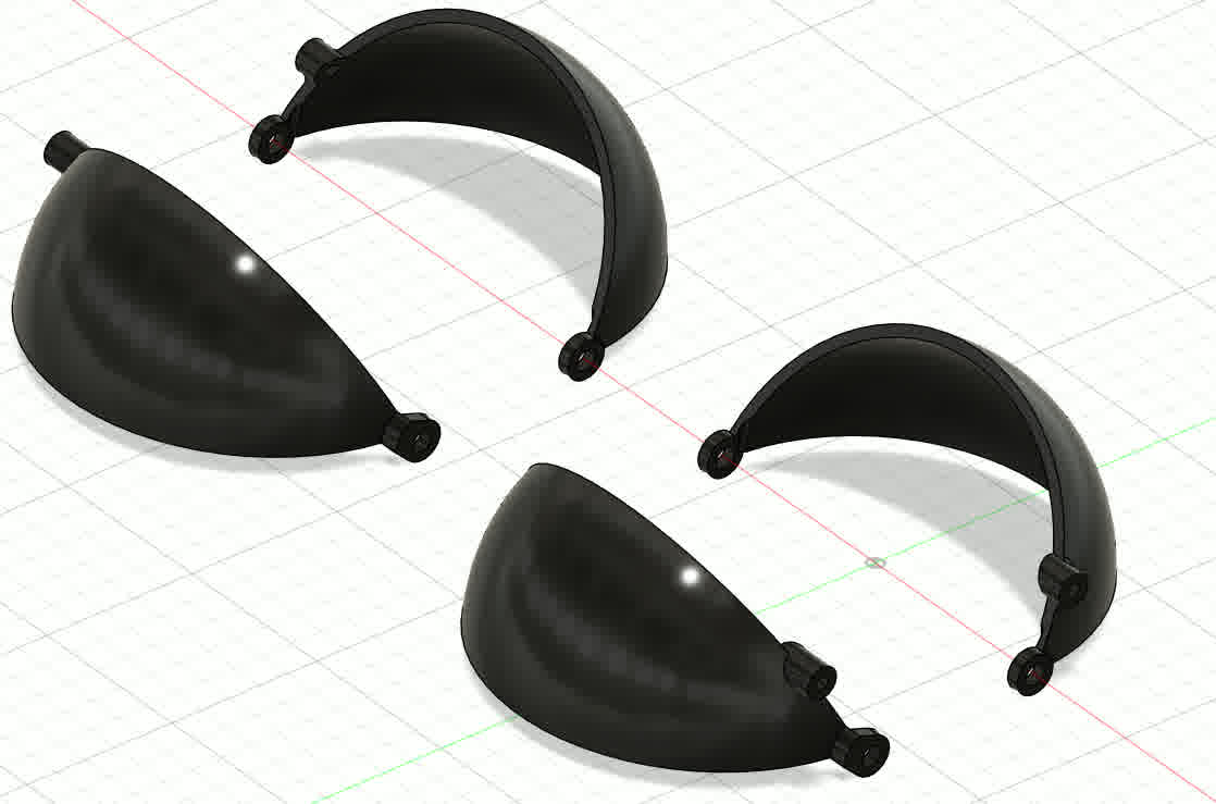
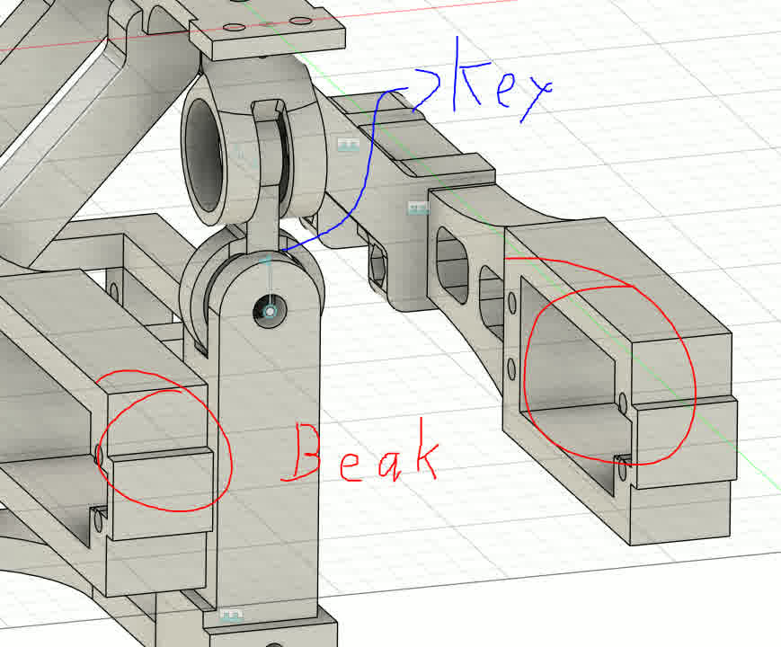
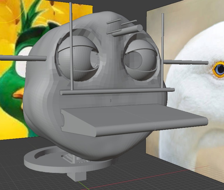
With the neck completed, I moved on to the beak. My design philosophy here focused on balancing strength and lightness. The lower beak, which moves, needed to be durable. I printed the core structure in PLA with 15% infill and designed it to support additional components and mounting features. I also began modeling aesthetic features using Blender, to give the animatronic a more expressive, lifelike appearance.
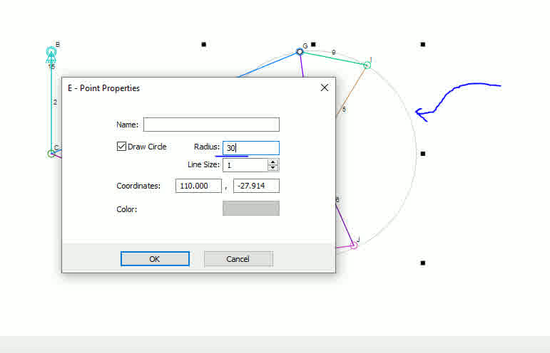
Also, here are the bars for the servomotors and some parts that will be used to connect the exoskeleton to the housing. For the measurement of the rods I actually used a prototype assembly to take into account how everything was looking.
Here is the final assembly in Fusion360.
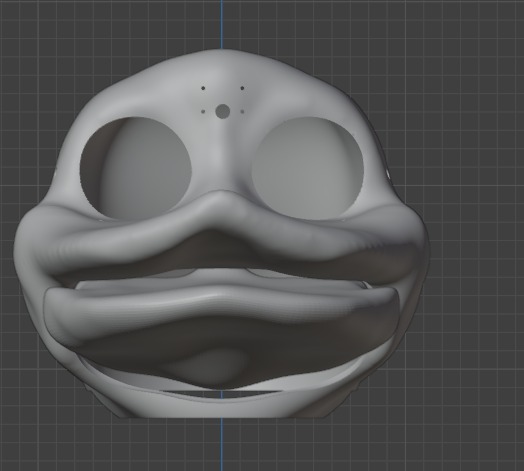
Blender time!!
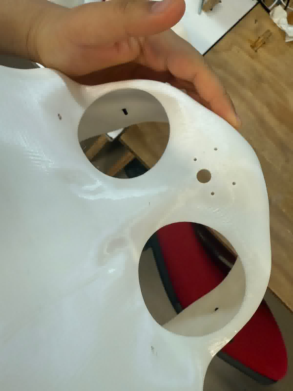
I experimented with ideas for the outer casing and skin of the animatronic. Inspired by animatronic characters like “Walt el pato animatrónico”, I plan to design a flexible mask, possibly cast in silicone or FlexFoam. The outer casing would act as the skull, and the flexible covering as the skin. The design is still in progress, but in my free time I am exploring new ways to sculpt the surface using digital models and physical molds (this include clay, gypsum, fiberglass and silicone).
As for Blender, the truth is I have no idea how to even use it. I tried the program once at the beginning of FabAcademy, but honestly, I got lost quickly. I could only follow tutorials, but I couldn't do anything on my own. Then, in Week 5, I tried to pick it up again. This time, I understood more things, but many functions were still unclear to me. However, that week, I found that if I was going to try design in Blender, it would be with the sculpting tools. It's not that these tools are easier, more practical, or simpler to use; in fact, the process can be either very lengthy or very, very quick, depending on your skill as a sculptor (literally speaking). But honestly, these tools were easier for me to understand due to their simpler interface.
From here, while I could explain in detail how to use everything in Blender, sometimes even I don't get it. I would just recommend that, to sculpt, you start with a cube and apply 1 to 2 subdivisions at the beginning to start shaping from very basic polygons. This, in addition to making it easier to manage the mesh when it gets more complex, also helps prevent issues like the mesh breaking. So, the main brush I used to shape everything was "Grab." In theory, it's like working in "Edit Mode," as the brush literally moves the points. Therefore, even though this mesh might seem risky, it's actually the best, since it's genuinely molding the mesh.
Finally, what’s left is to make passes, take a coffee, and maybe look at some reference images. In my case, this took a while. The main issue with Blender is that, without a good addon, it's really complicated to make parametric shapes. So, making the casing wasn't an aesthetic challenge, but a geometric one. My solution was to assemble my animatronic with the greatest considerations possible, then bring it into Blender to create a shape closer to something real that I needed. To do this, I also made some protrusions in the areas where my animatronic needs holes to assemble the casing (screws). This is because the best tool I found to make cuts in Blender was the boolean operations. With these, you literally choose which element you want to combine, cut, or just take the intersection between them. This helped a lot. Then, to go from mesh to solid, I simply used the "Solidify" option, which literally adds another mesh and joins them to create a "thickness."
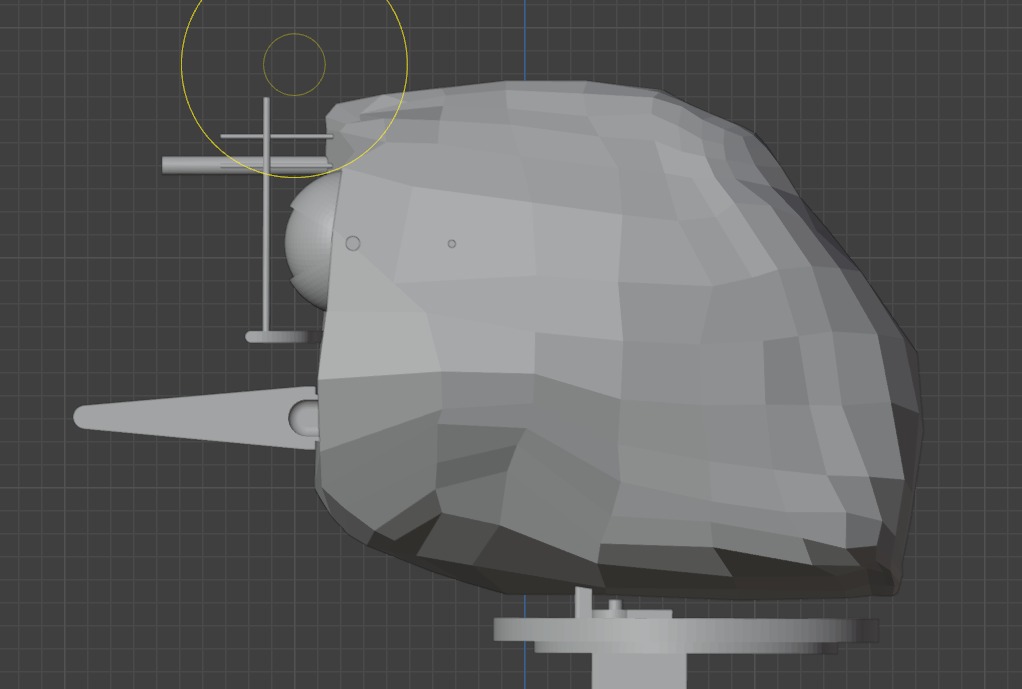
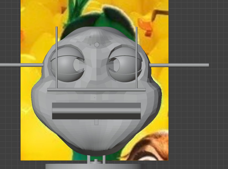
First poly
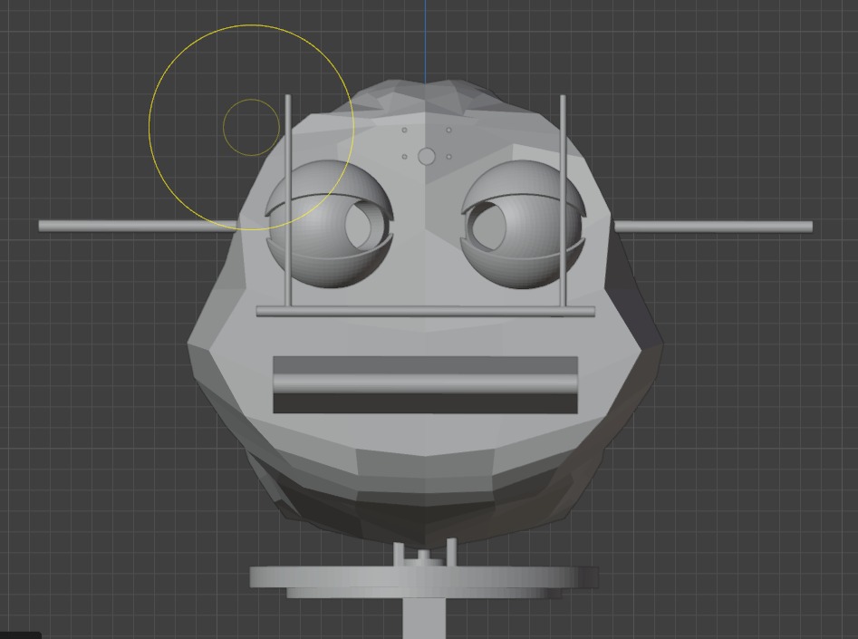
First poly another perspective
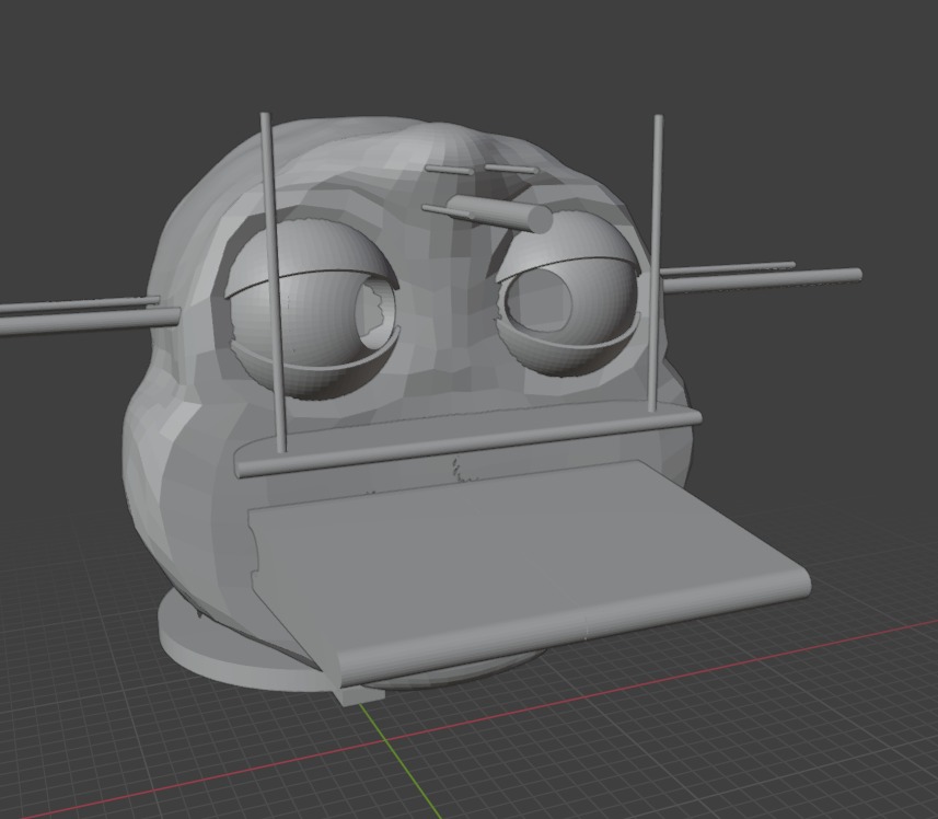
Second poly
Second poly another perspective
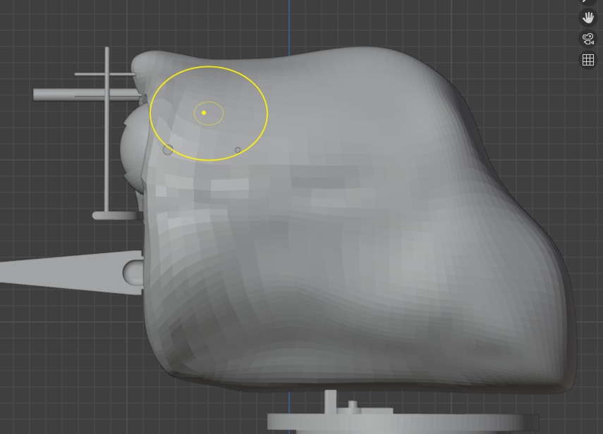
Better finishing and started to use some references
A more defined shape 1
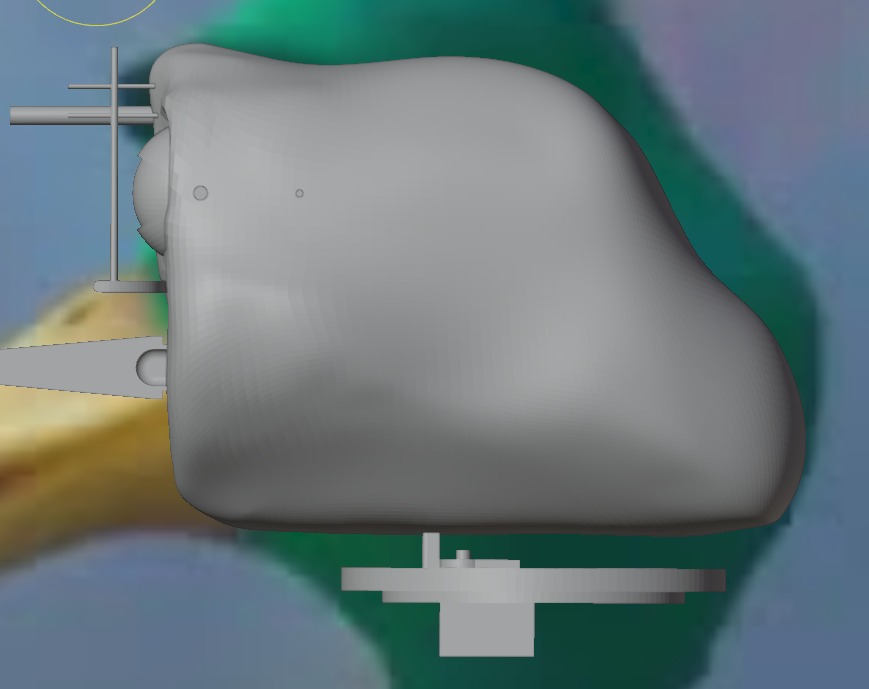
A more defined shape 2
.jpeg)
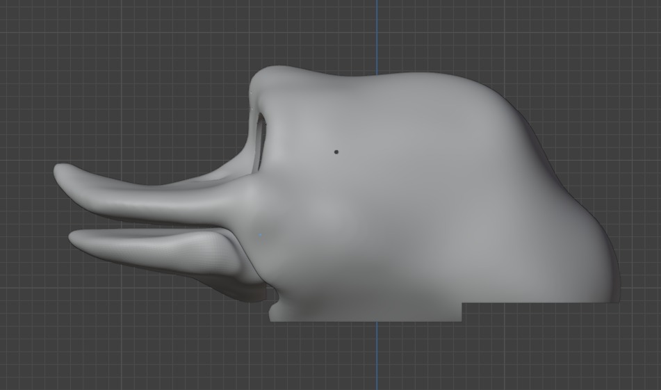
Third poly and starts to look great (Bread appereance)
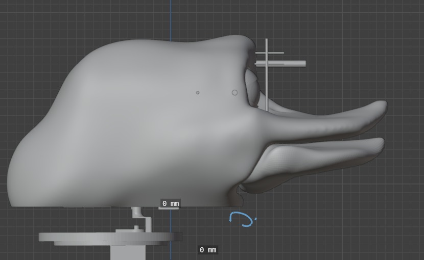
Side view
.jpeg)
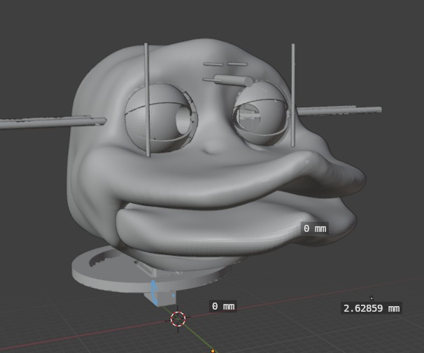
Eyes cutterd with boolean operation (also the holes of the assembly prevoiusly planned)
Now we are talking
Side view 2
All together
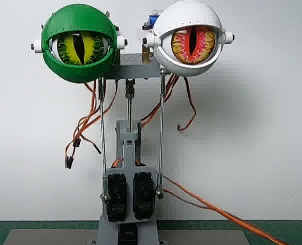
Results and some funny tests
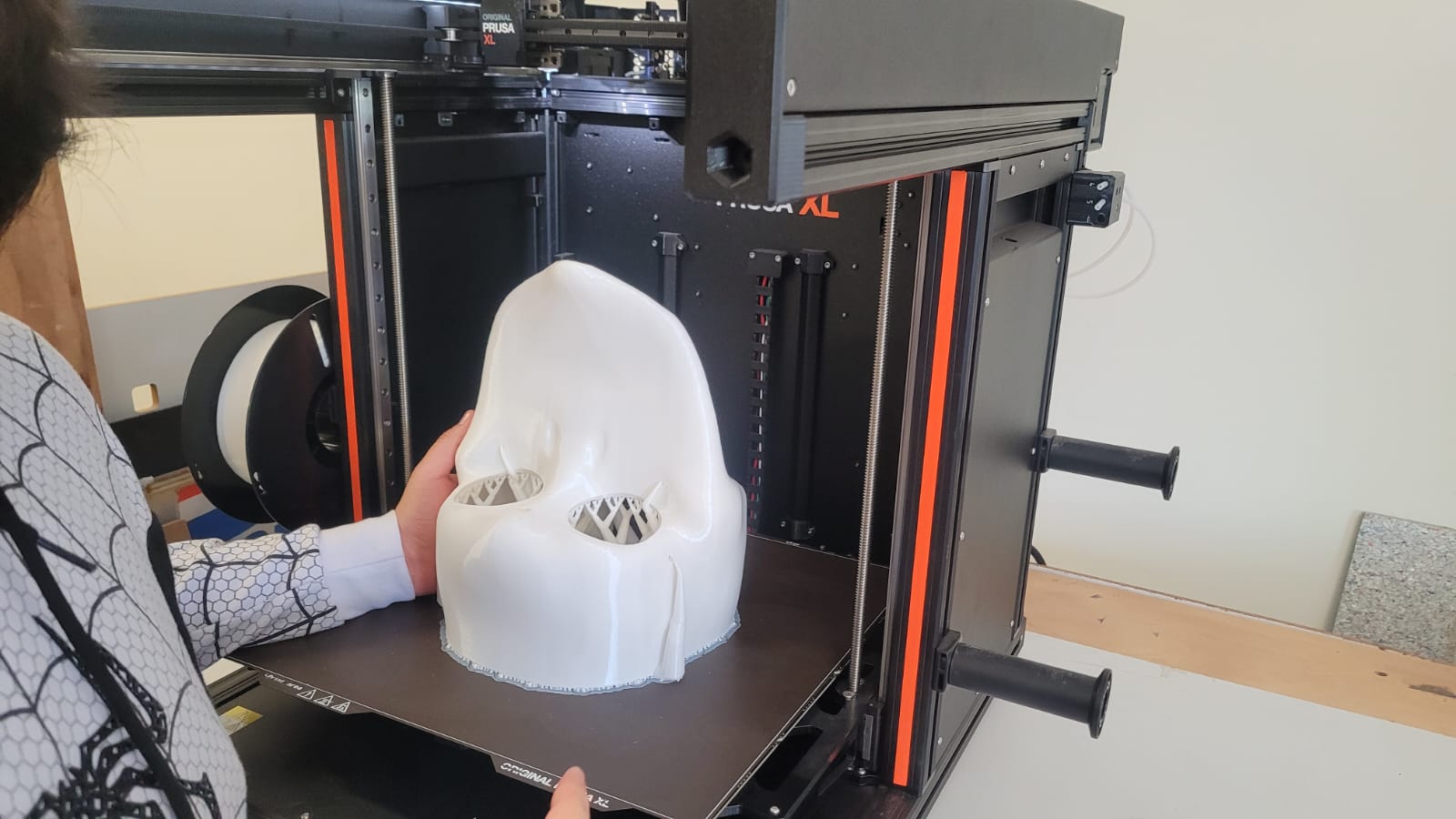
3D printing results
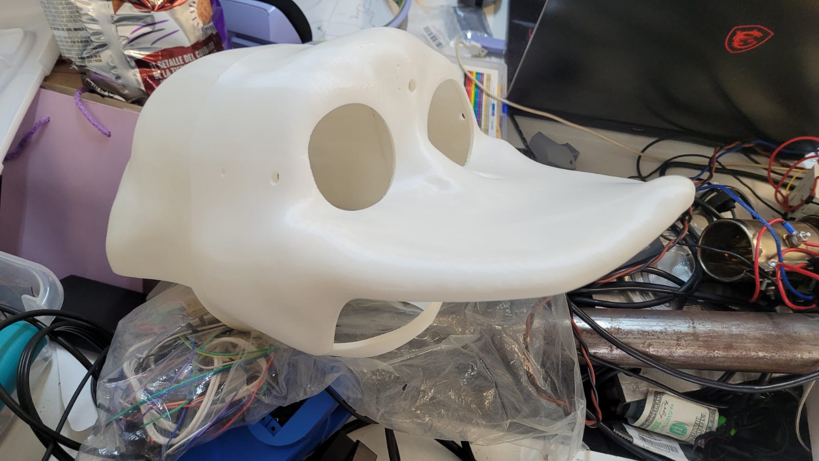
Results
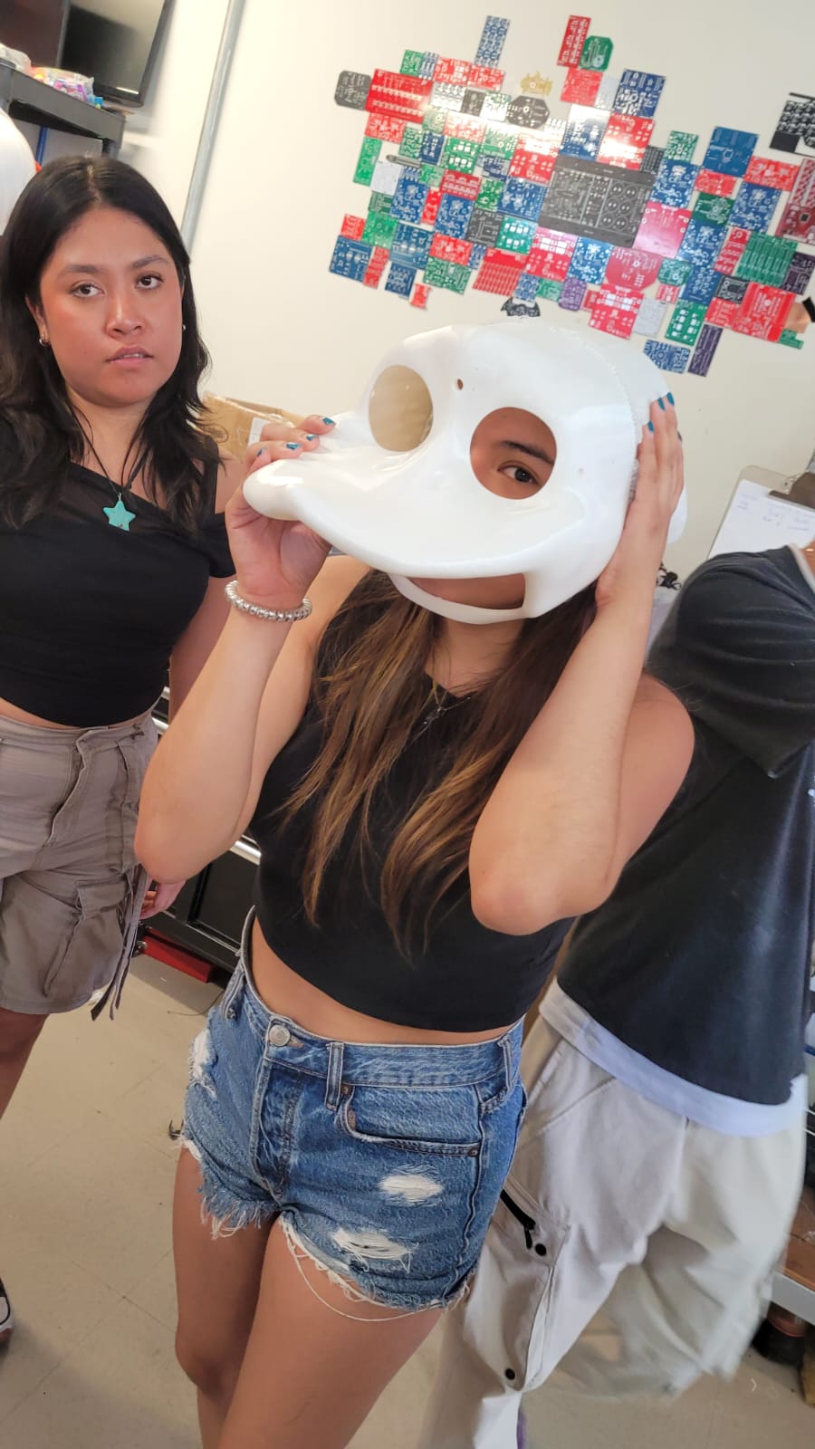
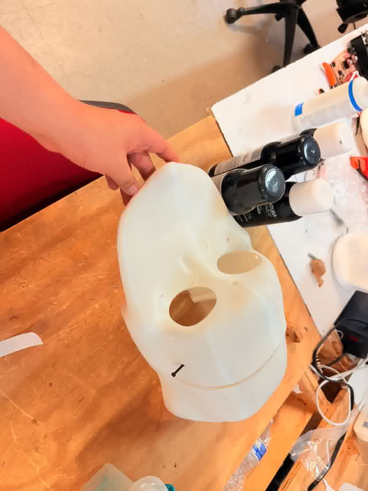
Literally everyone try to put it on
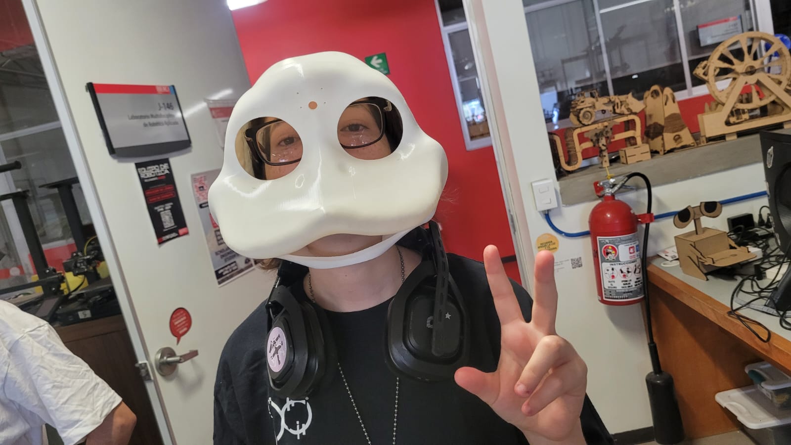
Xavi the mask
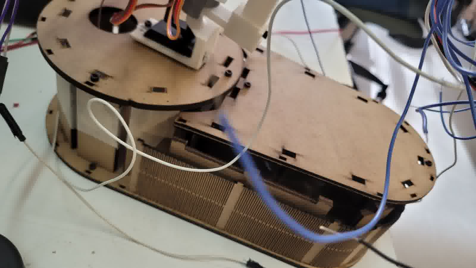
MDF structural base
For the MDF base, I simply wanted to create a shape that wasn't the traditional rectangular box. I aimed for something more curved, so I decided to make a solid structure of 5 mm (in the lab, we only have MDF of 2.5 mm or 3 mm, so I envisioned combining two 2.5 mm plates to achieve the necessary thickness). This, along with a 2.5 mm sheet that surrounds the "box" to give it a more curved appearance. At this point, I just let my creative freedom take over, and I only considered measurements for the LiPo battery and the ESP32 board created in Week 8.
Maybe not as simple as I thought
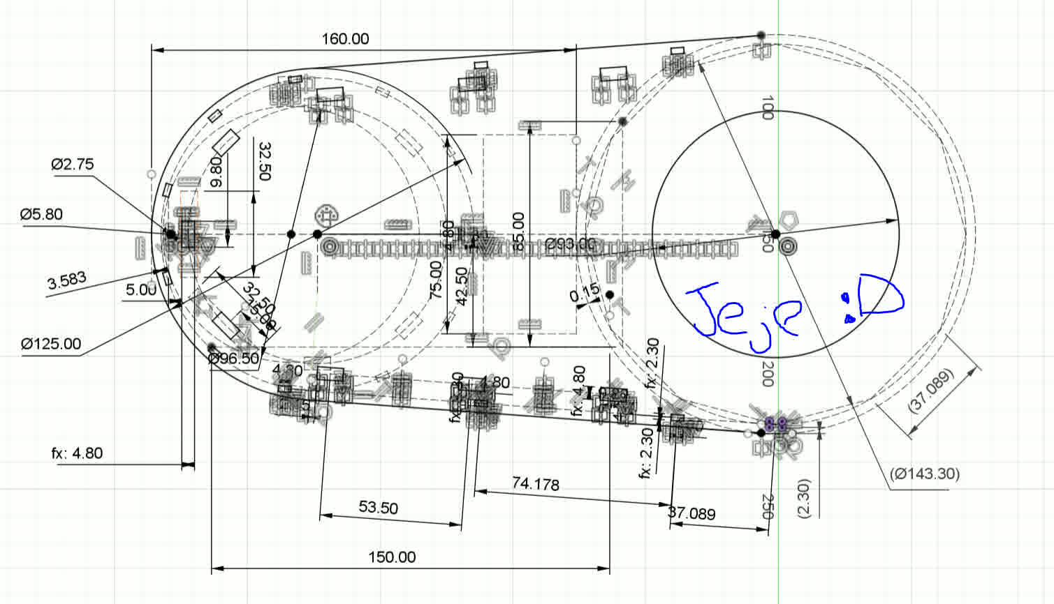
I may exaggerate with the measurements
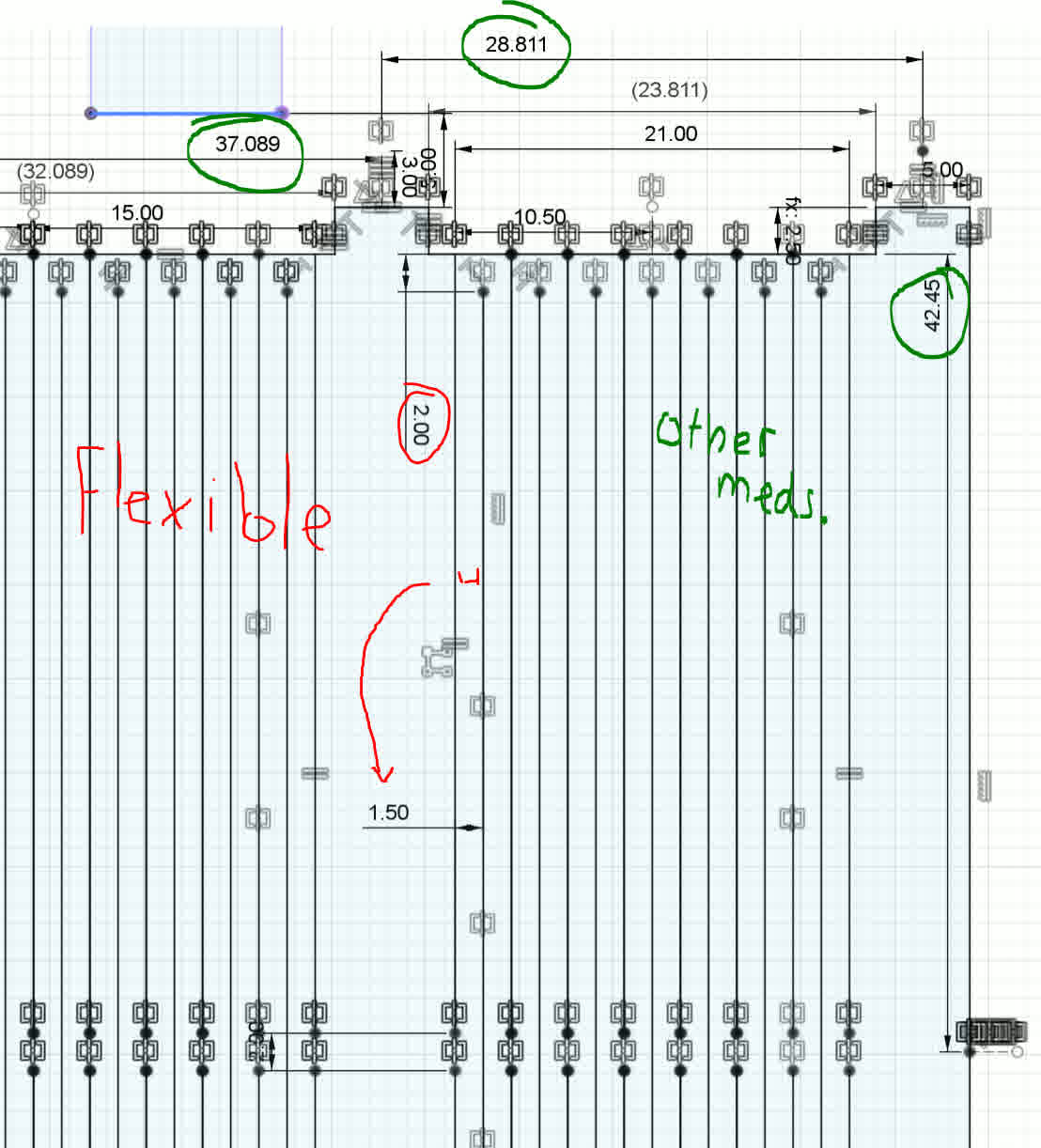
Flexible measurements
Electronics
As mentioned earlier, for the electronics, I will use the board developed in Week 8.
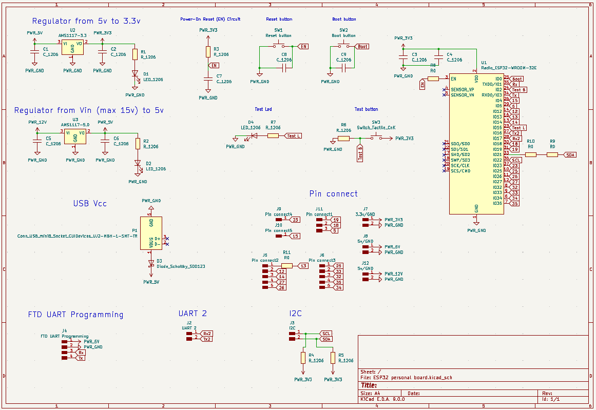
Pingu-board schematic
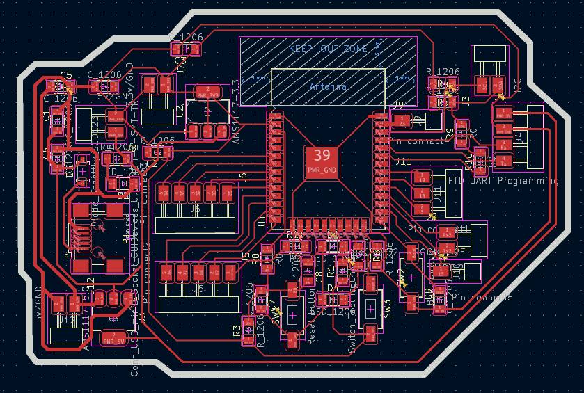
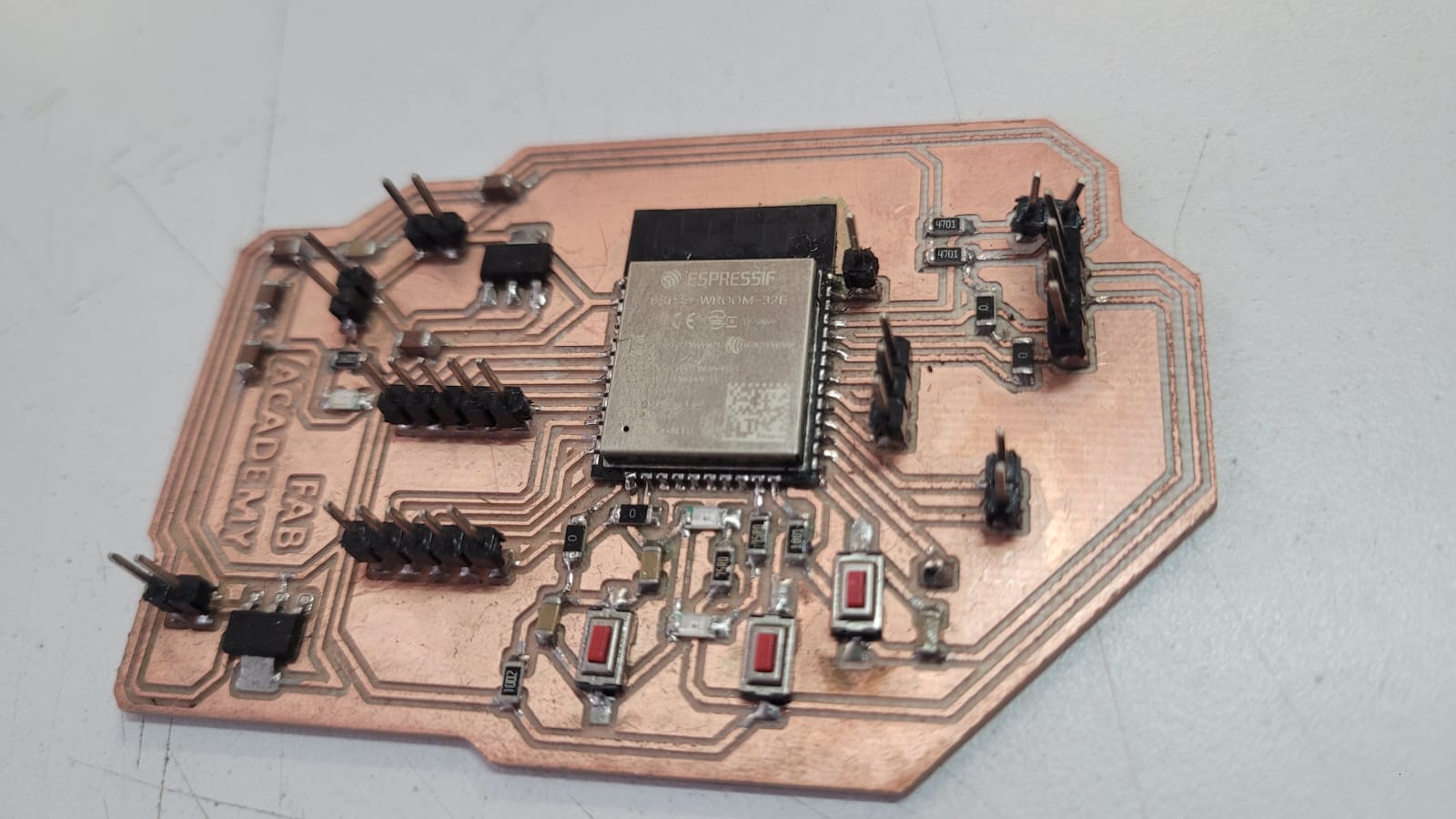
Pingu-board
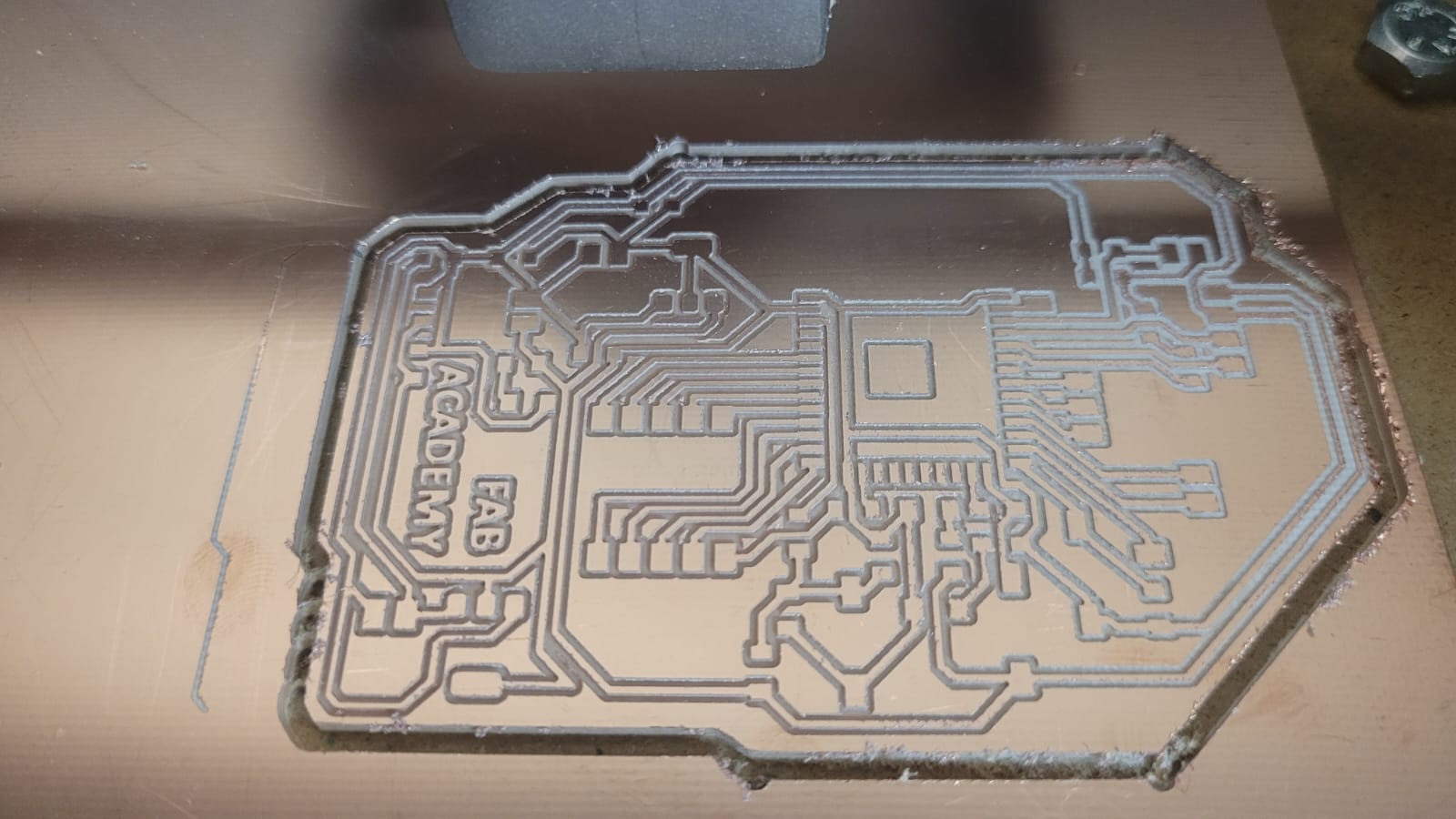
Manufacturing Result
The truth is, I wanted to design another PCB, but it’s not necessary. I really only need my microcontroller with enough pins to connect the TFTs via SPI (Unfortunately this never happened). Therefore, I just need to connect the module to control the drivers via I2C. The connection to the laptop can be either wireless, thanks to the ESP32, or via UART on the ESP32, either with my laptop or later with my Raspberry Pi. The camera is literally available on either of the two computers (my laptop or the Raspberry Pi with the Raspberry Pi Camera Module 2). So, as much as I wanted to create another board (because I truly want to, I enjoyed soldering and I find it relaxing), the truth is, I don’t need it. It's redundant.
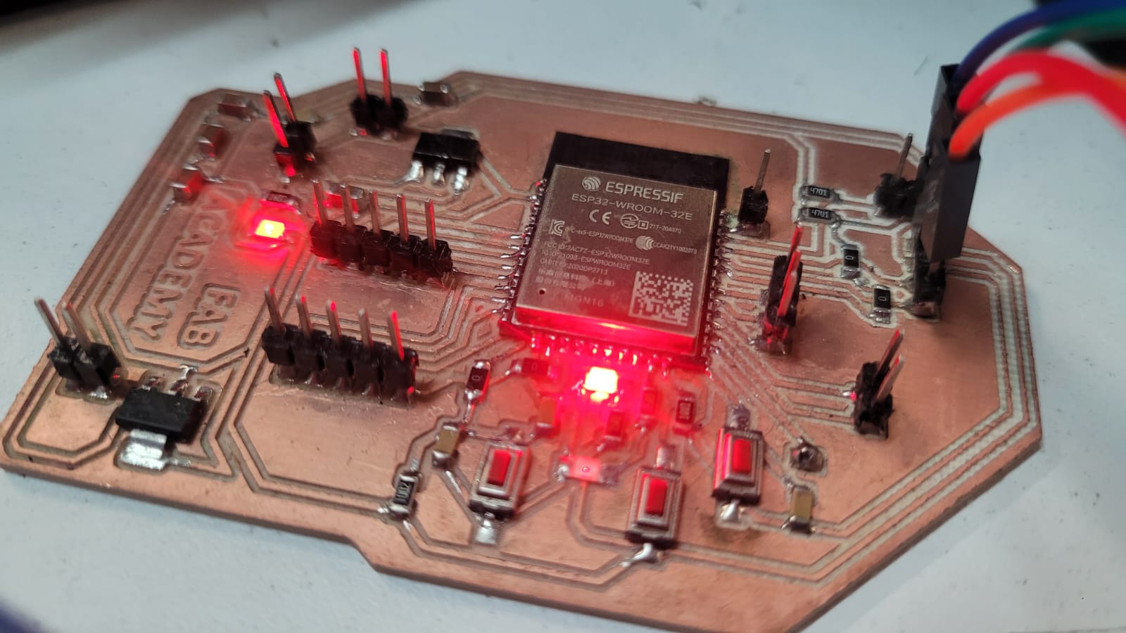
ESP32 Pingu-board
CODE
As for the code, it follows a simple logic; it literally just needs to track the person’s movement by considering the position of their nose at that precise moment. Regarding the servos for the eyes, they need to be reserved for small movements, so there needs to be a threshold large enough to ensure they only move when the person makes slight adjustments. However, for the neck movements, these servos do need to have a higher threshold. This threshold will be estimated during testing. Also, due to the nature of the mechanisms that don’t allow some servos to move their full 180°, the code itself has to establish limits to ensure they never exceed the specified parameter. Although this was simulated during assembly, it needs to be verified during testing, so the values are subject to those results.
Beyond that, the code remains simple. It communicates with the computer, which, in turn, sends data to it. But this only happens when the microcontroller needs it. This follows an ACK and NAK system. Therefore, the logic for entering the code must be non-blocking. This ensures smooth servo movement, proper communication with the computer, and the images shown on the TFTs.
// === Libraries === #include#include // === PCA9685 === Adafruit_PWMServoDriver pca = Adafruit_PWMServoDriver(); // === PWM Configuration === #define PWM_MIN 103 // Minimum PWM value (corresponds to 0 degrees) #define PWM_MAX 512 // Maximum PWM value (corresponds to 180 degrees) // === Servo Definitions === #define NECK_X 0 // X-axis of neck #define NECK_Y1 1 // Y1-axis of neck #define NECK_Y2 2 // Y2-axis of neck #define EYE_X1 13 // X-axis of eye 1 #define EYE_X2 10 // X-axis of eye 2 #define EYE_Y1 12 // Y-axis of eye 1 #define EYE_Y2 9 // Y-axis of eye 2 #define LID_1 11 // Lid 1 (first eyelid) #define LID_2 8 // Lid 2 (second eyelid) #define Beak_1 14 // Beak 1 (first Beak) #define Beak_2 15 // Beak 2 (second Beak) // === Eye Ranges === #define EYE_X1_MIN 85 // Minimum value for eye X1 movement #define EYE_X1_MAX 130 // Maximum value for eye X1 movement #define EYE_X2_MIN 35 // Minimum value for eye X2 movement #define EYE_X2_MAX 90 // Maximum value for eye X2 movement #define EYE_Y1_MIN 65 // Minimum value for eye Y1 movement #define EYE_Y1_MAX 130 // Maximum value for eye Y1 movement #define EYE_Y2_MIN 65 // Minimum value for eye Y2 movement #define EYE_Y2_MAX 130 // Maximum value for eye Y2 movement // === Lids Ranges === #define LID_1_MIN_ANGLE 0 // Minimum angle for Lid 1 #define LID_1_MAX_ANGLE 35 // Maximum angle for Lid 1 #define LID_2_MIN_ANGLE 180 // Minimum angle for Lid 2 #define LID_2_MAX_ANGLE 145 // Maximum angle for Lid 2 #define Beak_1_MIN_ANGLE 90 // Minimum angle for Beak 1 #define Beak_1_MAX_ANGLE 125 // Maximum angle for Beak 1 #define Beak_2_MIN_ANGLE 90 // Minimum angle for Beak 2 #define Beak_2_MAX_ANGLE 55 // Maximum angle for Beak 2 // === Neck Movement === #define MOVEMENT_THRESHOLD 28 // Threshold for neck movement #define CENTER_PERCENT 50 // Default center percentage #define CENTER_TOLERANCE 10 // Tolerance around center X=50, Y=50 (creates range 40-60) int neckPosX_percent = CENTER_PERCENT; // Current estimated neck position in X (0-100) int neckPosY_percent = CENTER_PERCENT; // Current estimated neck position in Y (0-100) int referenceX = CENTER_PERCENT; // Reference X-axis position for neck int referenceY = CENTER_PERCENT; // Reference Y-axis position for neck int currentPWM[16]; // Array holding the current PWM values for each servo int targetPWM[16]; // Array holding the target PWM values for each servo // === Movement Flags === bool enableNeckX = true; // Enable or disable neck X movement bool enableNeckY = true; // Enable or disable neck Y movement bool enableEyesX = false; // Enable or disable eye X movement bool enableEyesY = false; // Enable or disable eye Y movement bool enableLook = false; // Enable or disable special movement bool lookActionDone = true; // Enable or disable special movement with millis bool immediateMovementX = false; // Flag for immediate movement of eyes on X-axis bool immediateMovementY = false; // Flag for immediate movement of eyes on Y-axis bool lookValuesCaptured = false; // === Timers === unsigned long lastServoUpdate = 0; // Last time the servos were updated const unsigned long servoInterval = 20; // Interval for servo updates (in ms) unsigned long lastDataReceived = 0; // Last time data was received via serial const unsigned long serialTimeout = 10000; // Timeout for serial communication (in ms) unsigned long lastLook = 0; //Last time the eye servos started to move const unsigned long Lookactive = 7500; //Timeout for eyes movement // === Serial Communication === String serialBuffer = ""; // Buffer to store incoming serial data bool inputReady = false; // Flag to indicate if input is ready to be processed // === Blinking === #define BLINK_TIME_CLOSED 350 // Time for the eyelids to stay closed (in ms) unsigned long blinkTimes[] = { 3150, 4300, 7480, 3700, 4150, 7740, 3500, 4300, 1500, 7600, 1300, 6300, 2150, 3150, 4120 }; // Array of different blink times for each blink cycle int blinkIndex = 0; // Current index of the blink time unsigned long nextBlinkTime = 0; // Time for the next blink bool closedEyelid = false; // Flag to indicate if the eyelid is closed unsigned long closedStartTime = 0; // Time when the eyelid was closed int CurrentY1; int CurrentY2; void setup() { Serial.begin(115200); // Start the serial communication Wire.begin(); // Start I2C communication pca.begin(); // Initialize the PCA9685 PWM driver pca.setPWMFreq(50); // Set PWM frequency for servos nextBlinkTime = millis() + blinkTimes[blinkIndex]; // Set the time for the first blink // Initialize current PWM values to center position for (int i = 0; i < 3; i++) { currentPWM[i] = map(CENTER_PERCENT, 0, 100, PWM_MIN, PWM_MAX); } // Center neck at startup and update estimated position targetPWM[NECK_X] = map(CENTER_PERCENT, 0, 100, PWM_MIN, PWM_MAX); targetPWM[NECK_Y1] = map(CENTER_PERCENT, 0, 100, PWM_MIN, PWM_MAX); targetPWM[NECK_Y2] = map(100 - CENTER_PERCENT, 0, 100, PWM_MIN, PWM_MAX); neckPosX_percent = CENTER_PERCENT; neckPosY_percent = CENTER_PERCENT; } void loop() { unsigned long now = millis(); // Current time in milliseconds readSerial(); // Read incoming serial data if (inputReady) { // If input data is ready parseCommand(serialBuffer, now); // Parse the incoming command Serial.println("ok"); // Send acknowledgment serialBuffer = ""; // Clear the serial buffer inputReady = false; // Reset input ready flag lastDataReceived = now; // Update last data received time } if (now - lastDataReceived > serialTimeout) { // If no data received for a while centerServos(); // Center the servos } if (now - lastServoUpdate >= servoInterval) { // If it's time to update the servos lastServoUpdate = now; for (int i = 0; i < 16; i++) { bool immediateMove = false; if ((i == EYE_X1 || i == EYE_X2) && immediateMovementX) immediateMove = true; if ((i == EYE_Y1 || i == EYE_Y2) && immediateMovementY) immediateMove = true; if (immediateMove || abs(currentPWM[i] - targetPWM[i]) <= 2) { currentPWM[i] = targetPWM[i]; } else { currentPWM[i] = currentPWM[i] * 0.95 + targetPWM[i] * 0.05; // Smooth transition } pca.setPWM(i, 0, currentPWM[i]); // Set the PWM for each servo } } updateBlinking(now); // Handle blinking logic } void readSerial() { while (Serial.available()) { char c = Serial.read(); // Read each character from the serial buffer if (c == '\n') inputReady = true; // Mark input as ready when a newline is received else serialBuffer += c; // Add character to the buffer } } void parseCommand(String input, unsigned long now) { input.trim(); // Remove leading and trailing whitespace input += ' '; // Add a space at the end to help with parsing int x = referenceX, y = referenceY; // Default positions // Find the X and Y values in the input string int ix = input.indexOf('X'); int iy = input.indexOf('Y'); if (ix != -1) x = input.substring(ix + 1, input.indexOf(' ', ix)).toInt(); if (iy != -1) y = input.substring(iy + 1, input.indexOf(' ', iy)).toInt(); // === CORRECTED NECK MOVEMENT LOGIC === // Calculate relative steps from current neck position to target int stepsX = x - neckPosX_percent; // Steps needed in X int stepsY = y - neckPosY_percent; // Steps needed in Y // Check if target is within center tolerance (40-60 range) bool targetInCenterX = (x >= (CENTER_PERCENT - CENTER_TOLERANCE) && x <= (CENTER_PERCENT + CENTER_TOLERANCE)); bool targetInCenterY = (y >= (CENTER_PERCENT - CENTER_TOLERANCE) && y <= (CENTER_PERCENT + CENTER_TOLERANCE)); // Determine if neck should move based on thresholds bool moveNeckX = (abs(stepsX) >= MOVEMENT_THRESHOLD); bool moveNeckY = (abs(stepsY) >= MOVEMENT_THRESHOLD); // === Neck X Movement === if (moveNeckX) { // Move neck with relative steps, respecting limits int newPosX = constrain(neckPosX_percent + stepsX, 0, 100); targetPWM[NECK_X] = map(newPosX, 0, 100, PWM_MIN, PWM_MAX); neckPosX_percent = newPosX; // Update estimated position // Update reference only when neck actually moves referenceX = neckPosX_percent; // Disable eye movement and center eyes when neck moves immediateMovementX = false; enableEyesX = false; centerEyesX(); } else if (!targetInCenterX) { // If target is outside center tolerance but below movement threshold, use eyes int angleX1 = map(x, 0, 100, EYE_X1_MIN, EYE_X1_MAX); int angleX2 = map(x, 0, 100, EYE_X2_MIN, EYE_X2_MAX); targetPWM[EYE_X1] = map(angleX1, 0, 180, PWM_MIN, PWM_MAX); targetPWM[EYE_X2] = map(angleX2, 0, 180, PWM_MIN, PWM_MAX); immediateMovementX = (x > 50); enableEyesX = true; } else { // Target is within center tolerance - center eyes centerEyesX(); enableEyesX = false; } // === Neck Y Movement === if (moveNeckY) { // Move neck with relative steps, respecting limits int newPosY = constrain(neckPosY_percent + stepsY, 0, 100); targetPWM[NECK_Y1] = map(newPosY, 0, 100, PWM_MIN, PWM_MAX); targetPWM[NECK_Y2] = map(100 - newPosY, 0, 100, PWM_MIN, PWM_MAX); neckPosY_percent = newPosY; // Update estimated position // Update reference only when neck actually moves referenceY = neckPosY_percent; // Disable eye movement and center eyes when neck moves immediateMovementY = false; enableEyesY = false; centerEyesY(); } else if (!targetInCenterY) { // If target is outside center tolerance but below movement threshold, use eyes int angleY1 = map(y, 0, 100, EYE_Y1_MIN, EYE_Y1_MAX); int angleY2 = map(y, 0, 100, EYE_Y2_MAX, EYE_Y2_MIN); targetPWM[EYE_Y1] = map(angleY1, 0, 180, PWM_MIN, PWM_MAX); targetPWM[EYE_Y2] = map(angleY2, 0, 180, PWM_MIN, PWM_MAX); immediateMovementY = (y > 50); enableEyesY = true; } else { // Target is within center tolerance - center eyes centerEyesY(); enableEyesY = false; } // === Look Action Logic === if (enableEyesX && enableEyesY){ if (!enableLook){ enableLook = true; lookActionDone = true; lastLook = now; if (!lookValuesCaptured) { CurrentY1 = currentPWM[NECK_Y1]; CurrentY2 = currentPWM[NECK_Y2]; lookValuesCaptured = true; } if ((239 <= CurrentY1 && CurrentY1 <= 375) || (239 <= CurrentY2 && CurrentY2 <= 375)) { lookActionDone = false; } } else if (!lookActionDone && (now - lastLook >= Lookactive)) { lookActionDone = true; targetPWM[NECK_Y1] = constrain(CurrentY1 + 20, PWM_MIN+25, PWM_MAX-25); targetPWM[NECK_Y2] = constrain(CurrentY2 - 20, PWM_MIN+25, PWM_MAX-25); targetPWM[Beak_1] = map(Beak_1_MAX_ANGLE, 0, 180, PWM_MIN, PWM_MAX); targetPWM[Beak_2] = map(Beak_2_MAX_ANGLE, 0, 180, PWM_MIN, PWM_MAX); } } if (!(enableEyesX && enableEyesY)) { enableLook = false; lookValuesCaptured = false; targetPWM[Beak_1] = map(Beak_1_MIN_ANGLE, 0, 180, PWM_MIN, PWM_MAX); targetPWM[Beak_2] = map(Beak_2_MIN_ANGLE, 0, 180, PWM_MIN, PWM_MAX); } } void centerServos() { targetPWM[NECK_X] = map(CENTER_PERCENT, 0, 100, PWM_MIN, PWM_MAX); // Center neck X targetPWM[NECK_Y1] = map(CENTER_PERCENT, 0, 100, PWM_MIN, PWM_MAX); // Center neck Y1 targetPWM[NECK_Y2] = map(100 - CENTER_PERCENT, 0, 100, PWM_MIN, PWM_MAX); // Center neck Y2 targetPWM[Beak_1] = map(Beak_1_MIN_ANGLE, 0, 180, PWM_MIN, PWM_MAX); targetPWM[Beak_2] = map(Beak_2_MIN_ANGLE, 0, 180, PWM_MIN, PWM_MAX); // Update neck position estimates when centering neckPosX_percent = CENTER_PERCENT; neckPosY_percent = CENTER_PERCENT; referenceX = CENTER_PERCENT; referenceY = CENTER_PERCENT; centerEyesX(); // Center eyes X centerEyesY(); // Center eyes Y } void centerEyesX() { int angleX1 = (EYE_X1_MIN + EYE_X1_MAX) / 2; // Calculate the midpoint for eye X1 int angleX2 = (EYE_X2_MIN + EYE_X2_MAX) / 2; // Calculate the midpoint for eye X2 targetPWM[EYE_X1] = map(angleX1, 0, 180, PWM_MIN, PWM_MAX); // Set PWM for eye X1 targetPWM[EYE_X2] = map(angleX2, 0, 180, PWM_MIN, PWM_MAX); // Set PWM for eye X2 } void centerEyesY() { int angleY1 = (EYE_Y1_MIN + EYE_Y1_MAX) / 2; // Calculate the midpoint for eye Y1 int angleY2 = (EYE_Y2_MIN + EYE_Y2_MAX) / 2; // Calculate the midpoint for eye Y2 targetPWM[EYE_Y1] = map(angleY1, 0, 180, PWM_MIN, PWM_MAX); // Set PWM for eye Y1 targetPWM[EYE_Y2] = map(angleY2, 0, 180, PWM_MIN, PWM_MAX); // Set PWM for eye Y2 } void updateBlinking(unsigned long now) { if (!closedEyelid && now >= nextBlinkTime) { int pwm1 = map(LID_1_MAX_ANGLE, 0, 180, PWM_MIN, PWM_MAX); // Set PWM for Lid 1 (open) int pwm2 = map(LID_2_MAX_ANGLE, 0, 180, PWM_MIN, PWM_MAX); // Set PWM for Lid 2 (open) pca.setPWM(LID_1, 0, pwm1); // Open Lid 1 pca.setPWM(LID_2, 0, pwm2); // Open Lid 2 closedEyelid = true; // Mark eyelid as closed closedStartTime = now; // Record the time eyelid was closed } else if (closedEyelid && now - closedStartTime >= BLINK_TIME_CLOSED) { int pwm1 = map(LID_1_MIN_ANGLE, 0, 180, PWM_MIN, PWM_MAX); // Set PWM for Lid 1 (closed) int pwm2 = map(LID_2_MIN_ANGLE, 0, 180, PWM_MIN, PWM_MAX); // Set PWM for Lid 2 (closed) pca.setPWM(LID_1, 0, pwm1); // Close Lid 1 pca.setPWM(LID_2, 0, pwm2); // Close Lid 2 closedEyelid = false; // Mark eyelid as open blinkIndex = (blinkIndex + 1) % (sizeof(blinkTimes) / sizeof(blinkTimes[0])); // Update blink index nextBlinkTime = now + blinkTimes[blinkIndex]; // Schedule next blink } }
  #!/usr/bin/python3
  from picamera2 import Picamera2
  import cv2
  import mediapipe as mp
  import time
  import sys
  import serial
  import os

  # === UART Communication (via GPIO pins using /dev/serial0) ===
  ser = None
  serial_connected = False

  def try_connect_serial():
      global ser, serial_connected
      if serial_connected:
          return  # Already connected, don't try again
      try:
          ser = serial.Serial('/dev/serial0', 115200, timeout=1)
          time.sleep(2)
          serial_connected = True
          print("[Serial] Successfully connected to /dev/serial0")
      except PermissionError:
          print("[Serial] ❌ Permission denied. Run: sudo usermod -a -G dialout $USER && sudo reboot")
          serial_connected = False
      except Exception as e:
          print(f"[Serial] ❌ Error connecting: {e}")
          serial_connected = False

  try_connect_serial()

  # === Camera Initialization ===
  picam2 = Picamera2()
  picam2.preview_configuration.main.size = (640, 480)
  picam2.preview_configuration.main.format = "RGB888"
  picam2.configure("preview")
  picam2.start()

  # === MediaPipe Initialization ===
  mp_face = mp.solutions.face_mesh
  mp_hands = mp.solutions.hands
  face_mesh = mp_face.FaceMesh(static_image_mode=False, max_num_faces=1)
  hands = mp_hands.Hands(static_image_mode=False, max_num_hands=1)

  # === General Mapping Function ===
  def map_range(value, in_min, in_max, out_min, out_max):
      return int((value - in_min) * (out_max - out_min) / (in_max - in_min) + out_min)

  # === Rock Gesture Detection ===
  def is_rock_gesture(landmarks):
      def is_extended(tip_id, pip_id):
          return landmarks[tip_id].y < landmarks[pip_id].y - 0.02
      def is_folded(tip_id, pip_id):
          return landmarks[tip_id].y > landmarks[pip_id].y + 0.02
      thumb = landmarks[4].x < landmarks[3].x - 0.02 or landmarks[4].x > landmarks[3].x + 0.02
      index = is_extended(8, 6)
      middle = is_folded(12, 10)
      ring = is_folded(16, 14)
      pinky = is_extended(20, 18)
      return thumb and index and middle and ring and pinky

  # === Control Variables ===
  gesture_counter = 0
  off_sent = [False] * 5
  rock_start_time = None
  last_detected_time = None
  prev_time = time.time()

  while True:
      if not serial_connected:
          try_connect_serial()

      frame = picam2.capture_array()
      img_rgb = cv2.cvtColor(frame, cv2.COLOR_BGR2RGB)
      result_face = face_mesh.process(img_rgb)
      result_hands = hands.process(img_rgb)

      # === Face Detection ===
      if result_face.multi_face_landmarks:
          for face_landmarks in result_face.multi_face_landmarks:
              nose = face_landmarks.landmark[1]
              cx = int(nose.x * frame.shape[1])
              cy = int(nose.y * frame.shape[0])
              x_percent = 100 - map_range(cx, 0, frame.shape[1], 0, 100)
              y_percent = 100 - map_range(cy, 0, frame.shape[0], 0, 100)
              command = f"X{x_percent} Y{y_percent}\n"
              if serial_connected:
                  try:
                      ser.write(command.encode('utf-8'))
                      print(f"[Serial →] Sending: {command.strip()}")
                      response = ""
                      t0 = time.time()
                      while "ok" not in response and (time.time() - t0 < 2.5):
                          if ser.in_waiting:
                              response = ser.readline().decode('utf-8', errors='ignore').strip()
                              print(f"[Serial ←] Received: {response}")
                  except Exception as e:
                      print(f"[Serial] ❌ Error during sending: {e}")
                      serial_connected = False

      # === Hand Detection ===
      if result_hands.multi_hand_landmarks:
          for hand_landmarks in result_hands.multi_hand_landmarks:
              if is_rock_gesture(hand_landmarks.landmark):
                  if rock_start_time is None:
                      rock_start_time = time.time()
                  last_detected_time = time.time()
                  elapsed = time.time() - rock_start_time
                  gesture_counter = min(int(elapsed), 5)

                  if serial_connected and not off_sent[gesture_counter - 1]:
                      try:
                          ser.write(f"OFF{gesture_counter}\n".encode('utf-8'))
                          print(f"[Serial →] Sending: OFF{gesture_counter}")
                          response = ""
                          t0 = time.time()
                          while "ok" not in response and (time.time() - t0 < 2.5):
                              if ser.in_waiting:
                                  response = ser.readline().decode('utf-8', errors='ignore').strip()
                                  print(f"[Serial ←] Received: {response}")
                          off_sent[gesture_counter - 1] = True

                          # Shutdown when reaching OFF4
                          if gesture_counter == 4:
                              print("[System] Rock gesture held for 4 seconds. Shutting down.")
                              picam2.stop()
                              if serial_connected:
                                  ser.close()
                              os.system("sudo shutdown now")
                      except Exception as e:
                          print(f"[Serial] ❌ Error during sending OFF: {e}")
                          serial_connected = False
                  break
      else:
          # If no gesture detected for 0.5 seconds, reset the gesture detection
          if last_detected_time is not None and time.time() - last_detected_time > 0.5:
              rock_start_time = None
              gesture_counter = 0
              off_sent = [False] * 5
              last_detected_time = None

  # === Finalize ===
  picam2.stop()
  if serial_connected:
      ser.close()
      print("[Serial] Port closed successfully.")
System integration
The design and assembly of the key animatronic mechanisms (eyes, eyelids, neck, and beak) followed a logical sequence. Starting with designing individual mechanisms using 2D and 3D CAD tools, then thinking about how each interferes with the other, and finally, designing a compact and self-contained base for the actuators and bars. Notably Fusion360 for mechanical design and Blender for sculpting the outer head case to provide an aesthetically pleasing finish. The animatronic head case fully encloses these mechanisms, protecting the components and unifying the system into a single cohesive unit. The base, fabricated from 2.5 mm thick MDF provides structural support for the entire assembly, with all PCBs and components securely mounted both within the head case and on the base itself. Also, almost the entire base is made up of two MDF boards placed side by side. So, the actual thickness is 5 mm.
My own wood covering
Perfect space for the tft, they are not even noticed
For the electronic integration, it focuses on the custom ESP32 microcontroller board interfacing with actuators and sensors. Integral to the animatronic’s expressiveness are the two 1.28" 240x240 pixel round TFT displays (GC9A01), which serve as dynamic eyes. These displays render high-resolution, smooth eye animations synchronized with the mechanical movements, providing enhanced visual feedback beyond purely mechanical actuation.
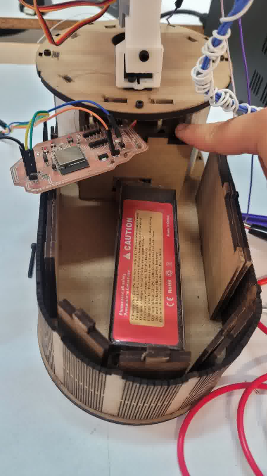
Designated space for the microcontroller and for the battery
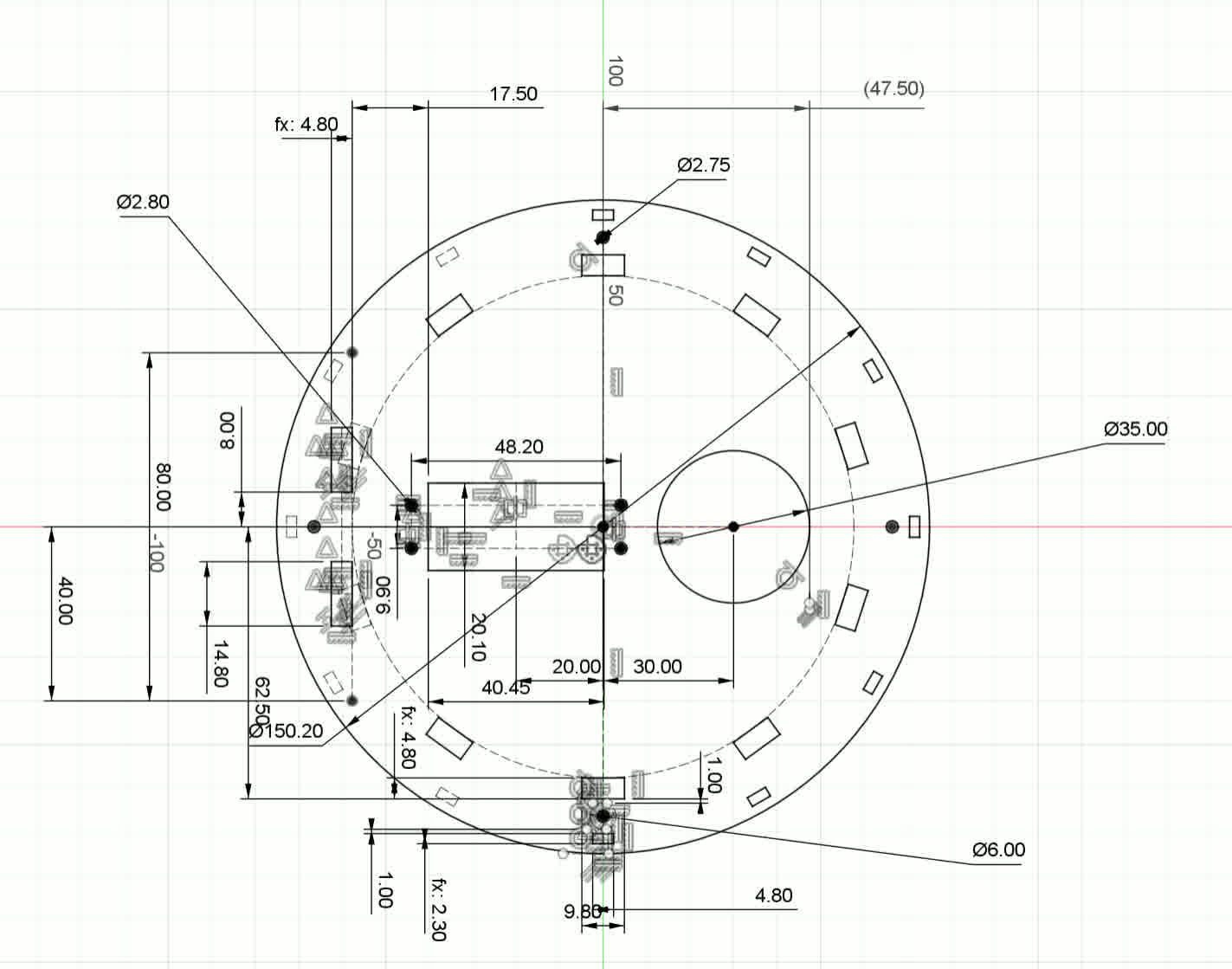
Servo actuation is managed through a dedicated PCA9685 PWM driver module, allowing precise, non-blocking control of multiple servomotors. This hardware abstraction simplifies signal generation for up to 11 servos, ensuring smooth and coordinated movements of the eyes, eyelids, neck, and beak mechanisms without burdening the microcontroller’s processing capabilities.
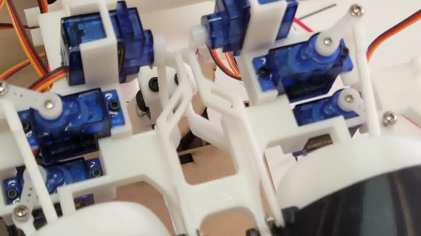
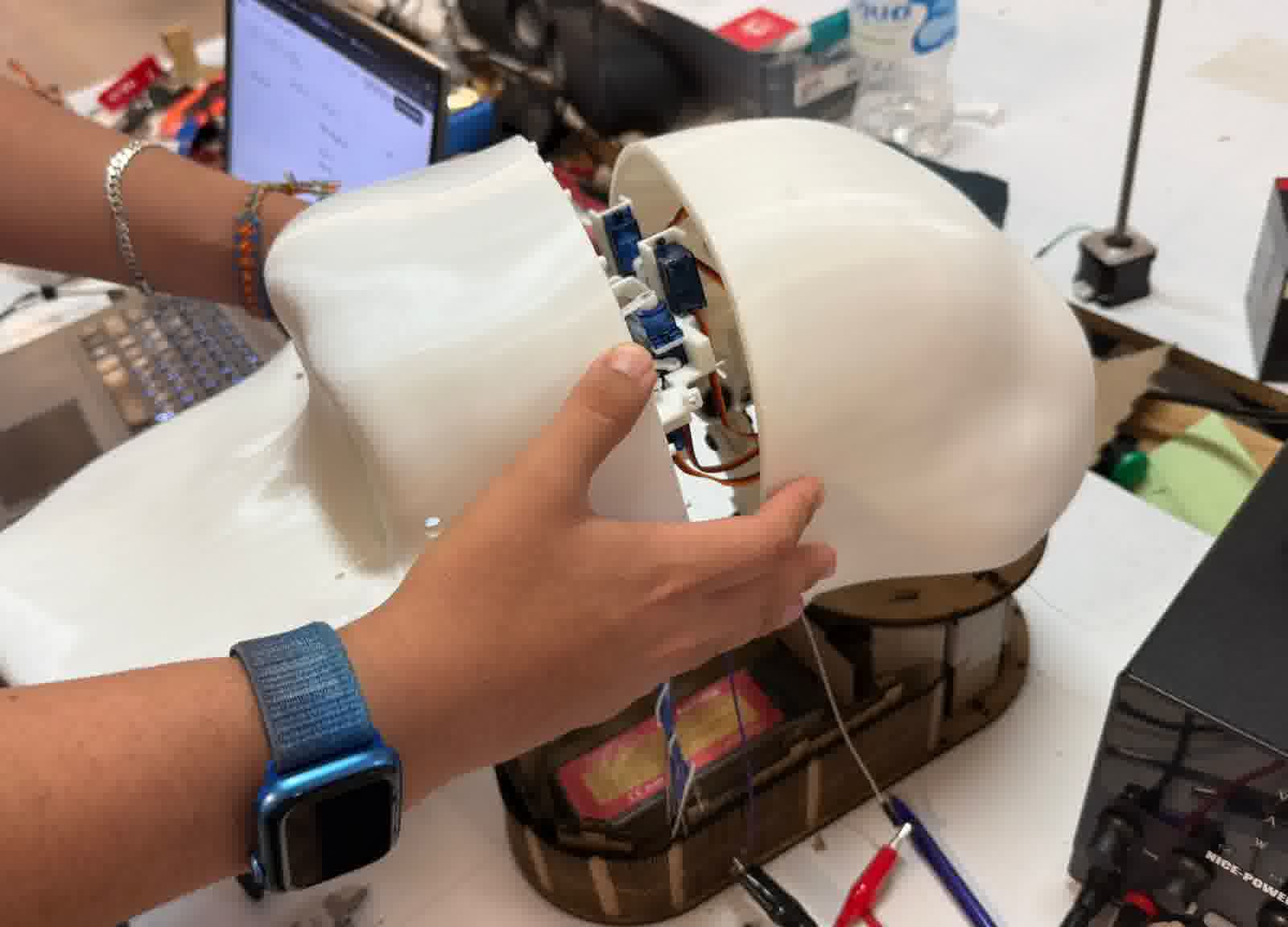
Arrangement of servomotors
Arrangement of servomotors 2
Wiring is carefully covered by soldering or connecting with proper headers and connectors (Duo-point). Wiring is routed neatly inside the head case and base, with cable management enhanced using plastic zip ties to secure cables, improving both reliability and aesthetics. All wiring is organized to avoid conflicts with moving parts, ensuring smooth operation and ease of maintenance.
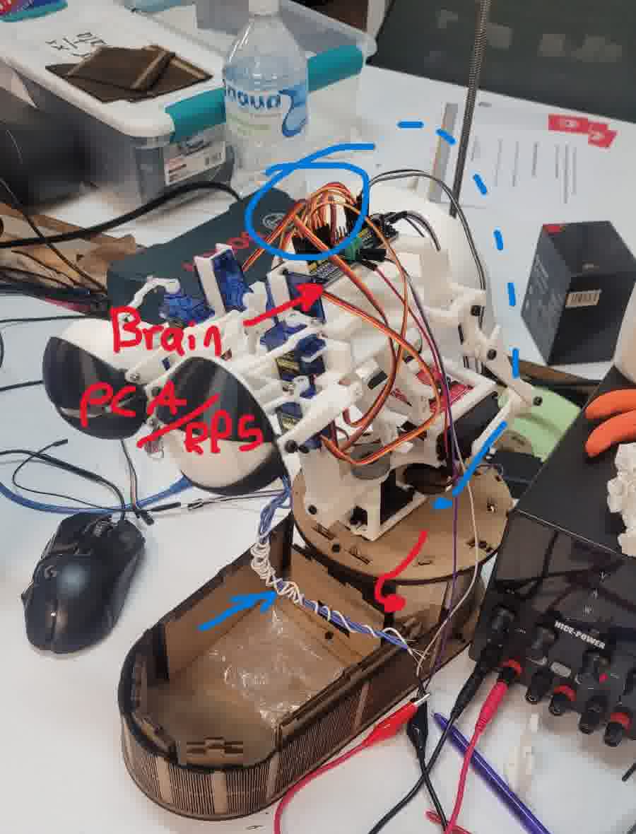
Cable management
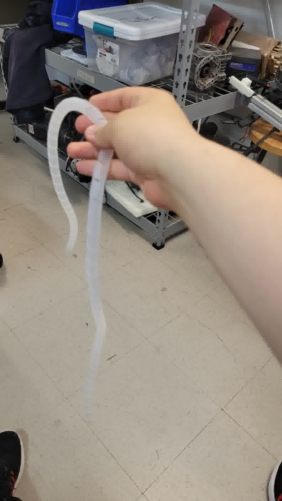
Cable to cover cables
In addition, I am implementing computer vision system using MediaPipe AI running on an external PC, which processes camera input to track human movement. The AI model generates tracking data sent to the embedded microcontroller via a communication protocol based on acknowledgment (Ack) and negative acknowledgment (Nack) for reliable data transfer. The camera interface draws a real-time figure of the person being tracked, enabling the animatronic to follow the movement fluidly.
Camera integration
Likewise, the goal is to integrate a computer as the brain inside the animatronic. That is, a Raspberry Pi 5 with its corresponding camera to process the MediaPipe model. My own laptop already does this, but this will be incorporated for a more discreet integration of the electronics.
For its part, both the raspberry pi 5 and its respective camera already have spaces designed for its incorporation either inside the housing of the face, as well as for the raspberry pi 5 has a special space under the module that controls the servos.
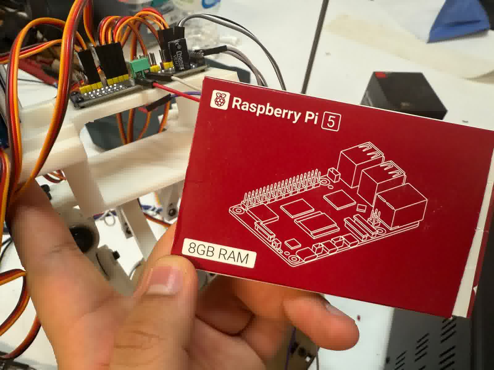
Space dedicated to the Raspberry pi 5
Cover case face
Now I am talking about it, all PCBs, actuators, and components are securely mounted in dedicated places inside the head case and on the MDF base. This organized packaging prevents damage and facilitates assembly and maintenance. The sculpted head case provides a polished, finished look that conceals cables and mechanisms, resulting in a product that appears professional and complete. Also since it is sculpted in Blender is visually pleasing. As well as, given that at the beginning of the sculpting in blender I based my own assembly made in fusion to have more realistic measurements with respect to the whole exoskeleton.
Finished product appereance
What does it do?
My project involves the creation of an animatronic head that tracks human movements smoothly. By using MediaPipe for real-time face recognition, the animatronic head is capable of coordinating its eye, eyelid, neck, and beak movements, providing an immersive and realistic interaction for viewers.
Who’s done what beforehand?
I conducted extensive research into various animatronic projects, particularly focusing on eye and neck mechanisms, which helped refine my understanding. Despite the references, every mechanical design, electronic integration, and overall system implementation has been original, with my personal touch in every aspect of the project.
What did you design?
The design process encompasses several subsystems, including the eyes, eyelids, neck, and beak. I created these components from scratch using both mechanical and 3D design techniques. The external casing was sculpted using Blender, while the structural base is crafted from MDF, and all electronics are built around a custom ESP32 PCB, ensuring a clean and seamless integration.
What materials and components were used?
The project relies heavily on 3D printing with PLA for complex mechanical parts and utilizes a 2.5mm MDF base for structural support. The movement mechanisms are powered by SG90/MG90S, MG996R, and TD-8120MG servos, which are controlled using a PCA9685 driver for synchronized motion. TFT displays (GC9A01) were initially planned to provide eye animation but were discarded due to wiring issues that resulted in visual noise. Instead, I used standard electronics for smooth operation.
Where did they come from?
All mechanical materials, including PLA filament and MDF sheets, were sourced from local FabLab resources. Electronic components, such as servos, display modules, and the ESP32 PCB, were ordered online. The sourcing ensures I have the necessary tools not only for this project but for future personal use as well.
How much did they cost?
The total cost of the project can be approximated by summing the prices of the various components used. The mechanical materials, including PLA filament, MDF sheets, and screws, contribute to the base cost, while the electronics—servos, displays, and drivers—further increase the overall expenditure. Based on the sourced prices from suppliers such as AliExpress, Amazon, and Digikey, the total cost for this project is estimated to be around $350 to $400 (a significant portion of the cost is attributed to the Raspberry Pi 5 and its related components).
What parts and systems were made?
All mechanical linkages, actuators, and mounts for the eyes, eyelids, neck, and beak were fabricated by me. The external casing and structural parts were also created through 3D printing. The custom ESP32 PCB, along with a PCA9685 servo controller, were assembled and programmed in-house to ensure precise communication between all the components.
What processes were used?
The project makes extensive use of additive manufacturing (3D printing) for the complex parts and subtractive techniques such as laser cutting for the MDF base. Electronics were hand-soldered with care to ensure a reliable and durable connection. The embedded software was developed specifically for real-time servo control, while AI integration was included for enhanced interactivity using a Raspberry Pi 5.
What questions were answered?
The overall movement of the system feels quite smooth and satisfying, and I am happy with how it turned out. Unfortunately, the TFT displays didn't work as expected, which impacted the visual quality, but the rest of the system still looks very good. Upon integrating all components, I found that everything generally works as it should, although the process of assembling everything proved to be somewhat complex. Nonetheless, this marks the final version for now, and it stands as a solid achievement.
What worked? What didn’t?
Most of the system is functioning as expected, with the neck and beak mechanisms performing reliably with fluid motion. The AI system tracks poses accurately, sending commands without loss. However, the eye mechanism, powered by SG90 servos, struggled with torque under load, causing occasional inconsistencies. As a result, I decided to leave out the servos for the head’s movement to avoid potential damage and to reduce strain on the system. The weight of the head (~3 kg) also limited portability, and the MDF base requires reinforcement to avoid disassembly.
How was it evaluated?
The evaluation is based on tracking accuracy, motion smoothness, appearance, and overall communication reliability. The subjective quality of engagement and the lifelike appearance of the animatronic head are also important metrics.
What has been done so far?
So far, I have designed and fabricated the main mechanical subsystems, including the eye, neck, and beak mechanisms. The head shell has been sculpted in Blender and printed, while the MDF base is complete and stable. The embedded code for servo control and AI communication is functional, and initial tests have shown promising results. The next step is to unify all components for the final integration and testing phase.
What did you learn?
This project strengthened my mechanical design and prototyping skills. I learned the importance of early integration planning and managing complex hardware-software coordination. Additionally, I improved my project management abilities and overcame challenges in fabrication. Regarding technical skills, I gained a deeper understanding of rotational motion mechanisms, especially when working in both X and Y axes. Tools like Fusion 360 and Blender were pivotal in bringing the project to life, and I plan to continue honing my Blender skills for more complex designs.
Documents!
Head (3D printing)
- Articulated joint head neck
- Base servo eyes
- Beak holder
- Beak holder_up
- Eye TFT holder
- Eye_ball
- Eyelids bars
- Eyelids
- Eyes X bars
- Eyes Y bars
- Mouth mecanism and neck joint
- Neck connect
- Neck joints bars