Project Development
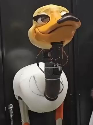
For my Final Project I am thinking of making an animatronic goose based on my university's pet.
Motivation and Research
I have always been interested in robotics and animatronics. Previously, I worked on a project to develop an animatronic octopus. although it taught me many things the hard way, I really enjoyed it. I want to correct my mistakes and create something much better. The idea of designing an animatronic based on "Javi," the university’s goose pet, initially came from a casual remark. However, it quickly evolved into a creative and funny idea.
I am not starting from scratch. There is already extensive research on the functionality of various robots, and even a YouTube channel, "Walt El Pato Animatronic", which serves as a valuable reference for my designs. However, my objective goes beyond simply replicating head and eye movements. Ideally, I would like to develop a bipedal robot, but for now, my primary focus will be to make it as visually appealing and friendly as possible (it is meant to represent the university's mascot!!).
UPDAAAATE!! After more than fourteen weeks of continuous development, I now have a much clearer understanding of my abilities, the challenges involved, and the scope of the animatronic project I'm building. Although I initially planned to design a full-body animatronic, including the head, neck, wings, torso, and possibly bipedal legs, I quickly realized that the most visually engaging component is the head. As a result, I decided to concentrate my efforts there, aiming to make it as dynamic and visually appealing as possible.
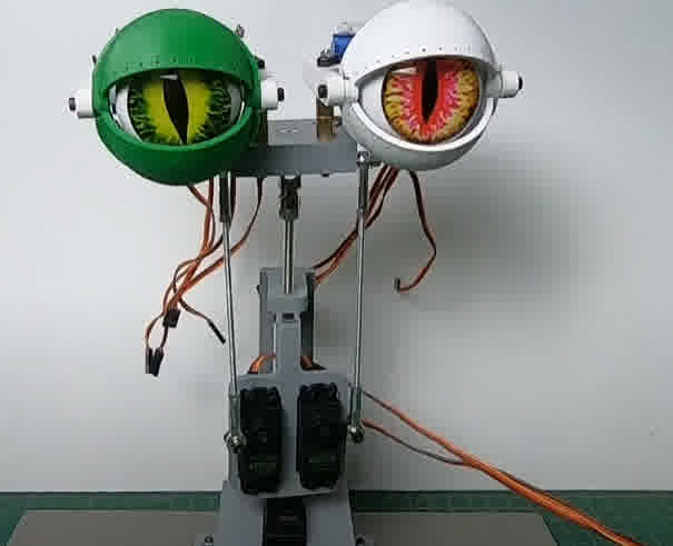
Walt animatronic example.
First Sketches
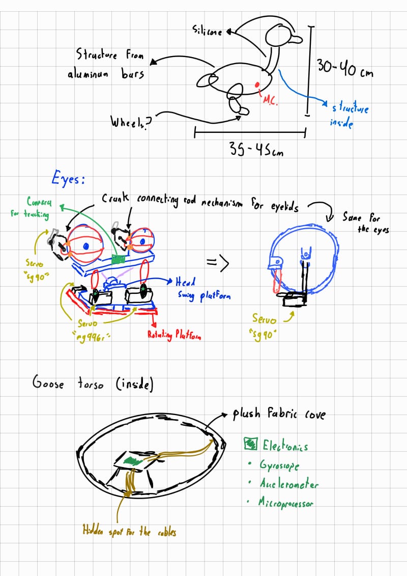
Very preliminary ideas. In the future I will continue with this project, but currently for my project I will only make the head and if posible the neck.
Deadlines (Midterm)!
| Task | Deadline | Notes |
|---|---|---|
| References for eye mechanism design | Last week of February to first week of March | Research and gather references for the eye mechanism design. |
| Design eye mechanism (fabrication) | Week of March 6-12 | Finalize the design of the eye mechanism and start fabrication. |
| Simulation of linkage for eyelids and design | Week of March 13-19 | Simulate the eyelid mechanism and begin design for fabrication. |
| Multiple designs for servo base (eyes) | Week of March 20-26 | Develop multiple base designs for the servos controlling the eyes. |
| Modify servo base for final fabrication | Last week of March to first week of April | Finalize modifications for the servo base design. |
| Design extensions for beak | Week of April 6-12 | Start the design of the beak extensions for the animatronic. |
| Design neck mechanism (3-axis movement) | Week of April 13-19 | Design and plan the neck mechanism, which allows movement in three axes. |
| Design bars for actuator servos | Week of April 20-26 | Design and plan the bars that will house the actuator servos. |
| Redesign servo base based on bar design (fabrication & testing) | Last week of April to first week of May | Revise and fabricate the servo base considering the bar mechanism. |
| Finalize redrawing and initial assemblies | Week of May 4-10 | Make final design adjustments and assemble the first parts. |
| Vision code (laptop), blender modeling of casing, base design and fabrication | Week of May 11-17 | Develop the vision code on laptop, model casing in Blender, and design and fabricate the base. |
| Model casing in Blender | Week of May 18-24 | Continue with the modeling of the casing for the animatronic head in Blender. |
| Complete Blender casing model and fabrication, refine ESP32 code | Week of May 25-31 | Finish the casing model and fabrication. Refine ESP32 code for smoother operation. |
| Final assembly, code testing, and parameter adjustments | Week of June 1-7 | Assemble all parts, test the code, and adjust parameters and thresholds based on testing. |
| Post-processing, video recording, slide preparation | June 7 to presentation day | Finish post-processing, record necessary videos, and prepare slides for presentation. |
Concepts and desing!
At best, my goal is to create a portable animatronic system. Instead of a stationary figure placed on a table (to begin with, I’ll take this step to ensure the overall integrity and proper functionality of the entire system), I envision a more interactive concept—a head mounted on a backpack, similar in style to the character Kazooie from "Banjo-Kazooie." This design would allow the animatronic to move, track people, and respond in real-time, making it more engaging for observers.

Kazooie idea reference.

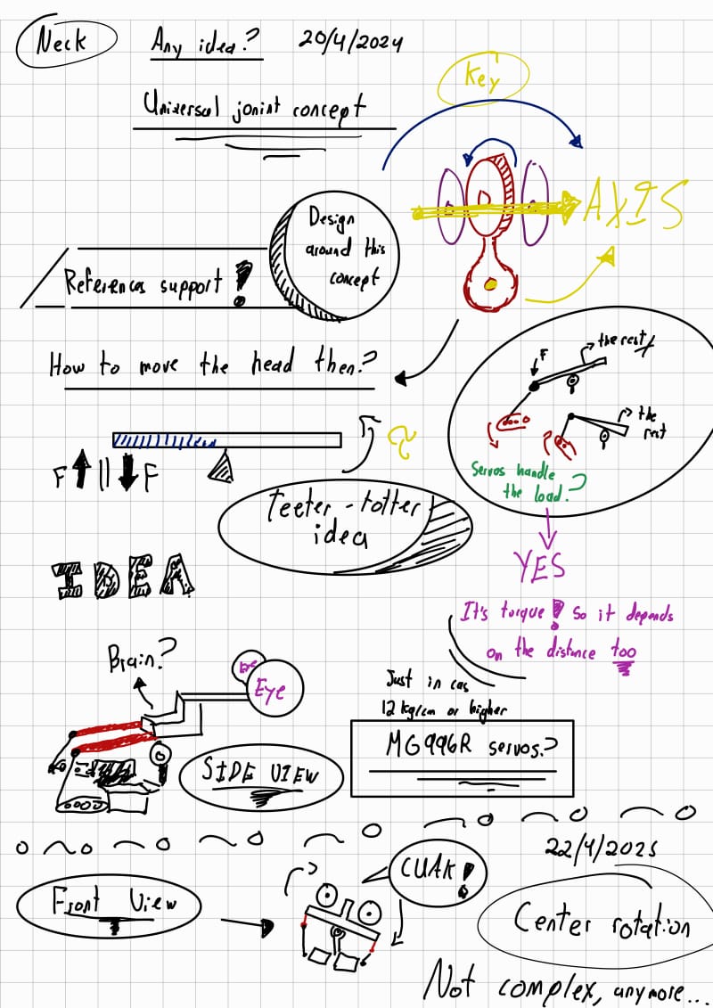
Initially, I considered limiting movement to the eyes. However, I soon decided that the neck should offer full motion across three degrees of freedom, not just left-right rotation. I wanted to replicate natural, fluid head movement.
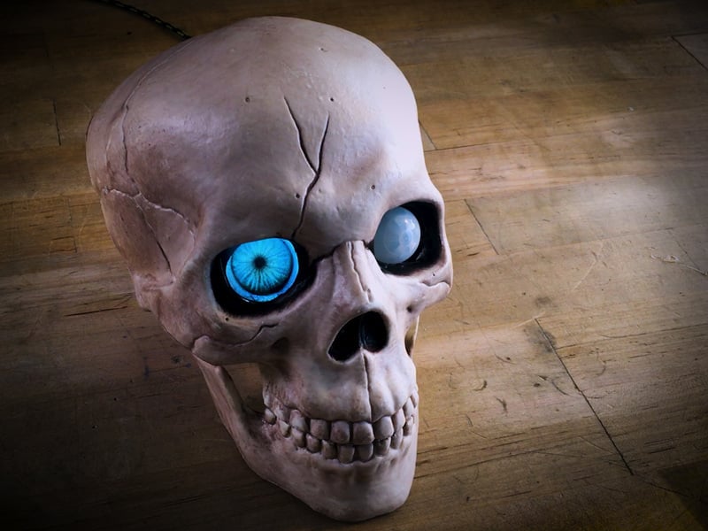
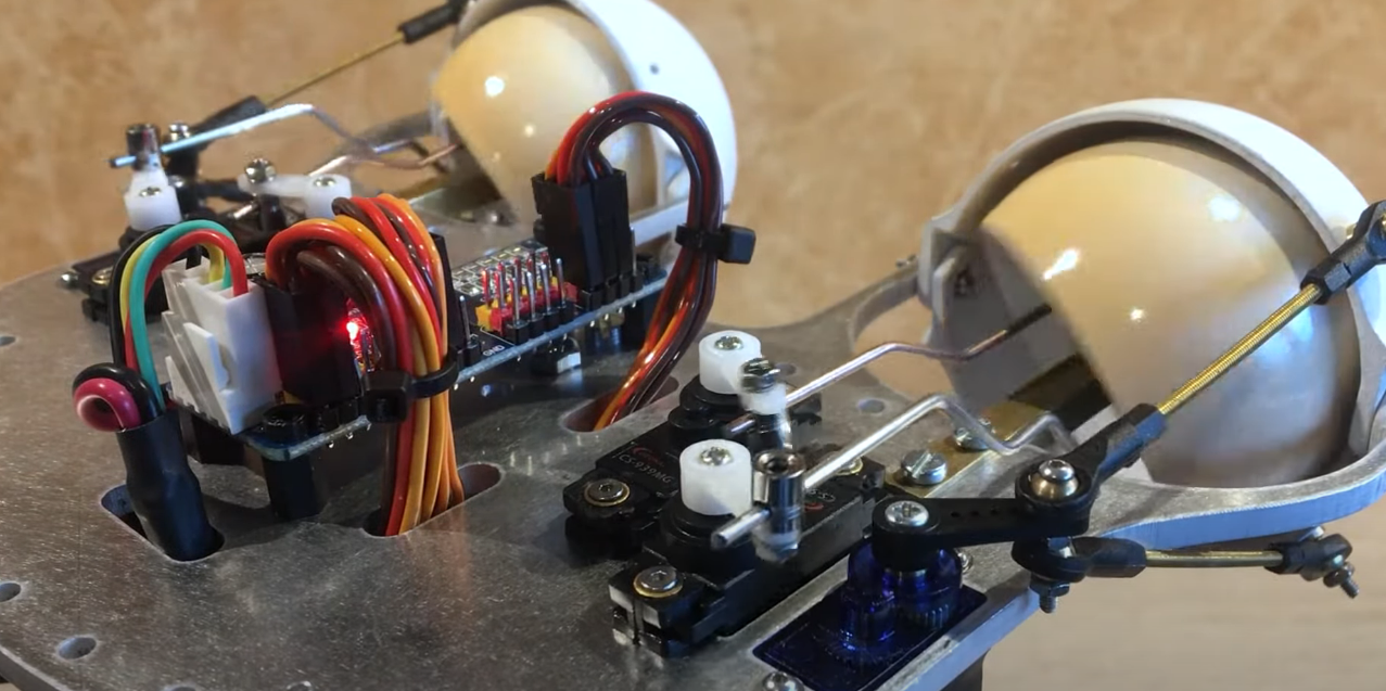
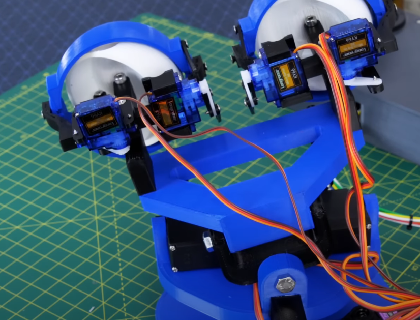
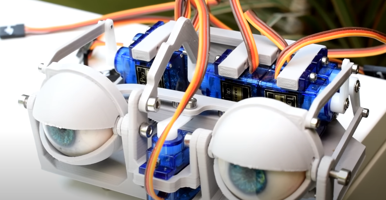
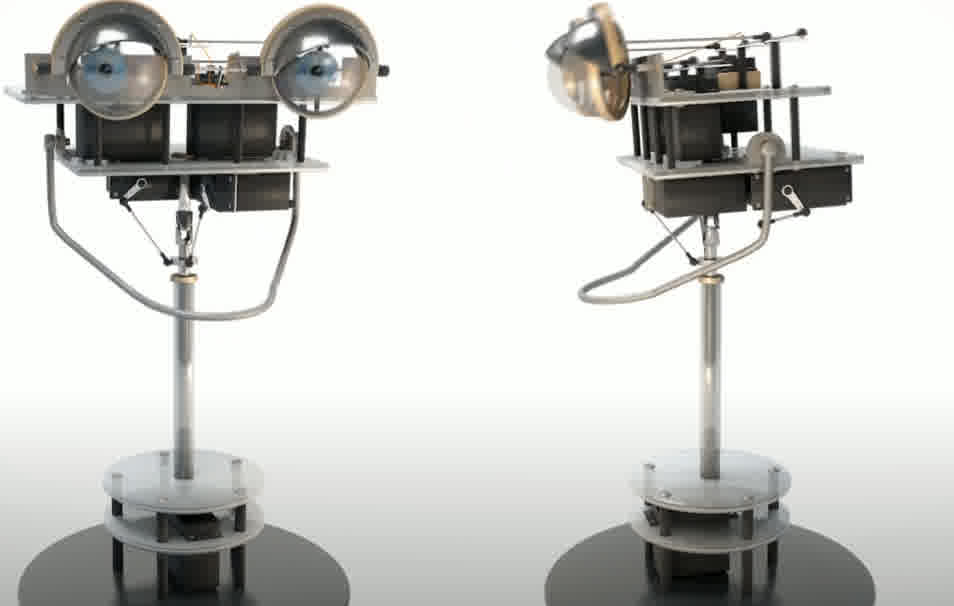
While researching existing animatronics, I noticed a trend: many developers simulate eye motion entirely through TFT displays. Although this solution reduces mechanical complexity, it has a major visual flaw. From a side view, these eyes appear unnatural. I wanted a more realistic result. Thus, I designed a hybrid system: the eyes would move mechanically, using a universal joint-like mechanism, while the irises would be represented using 240x240 GC9A01 round TFT screens. This combination allows for dynamic color or texture changes in the eye without sacrificing physical realism.
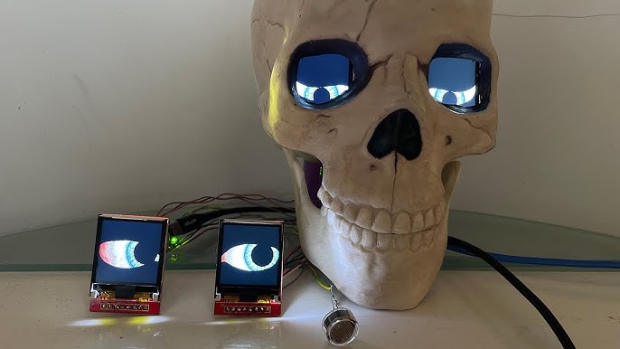
Example of unncany eyes.
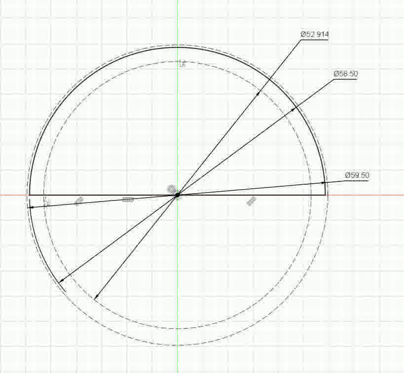
I am Erwin from the futureeeee! Just before continuing, a small detail... Choosing the GC9A01 displays impacted the entire design. Their size forced me to enlarge the eyes, which in turn increased the dimensions of the whole head. Although I made it work, in retrospect I would have preferred a smaller screen. I recommend others explore more screen options before committing to a design. I mention this because by the time I was moving forward with the rest of the things, I had already bought my displays and did not want to buy any more. So I decided to use the ones I already had. Mentioned this, lets continue
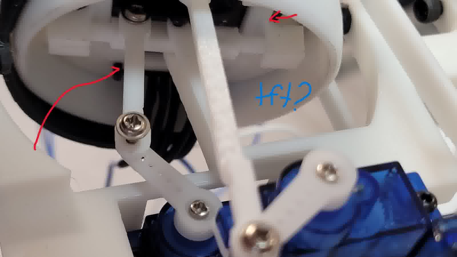
To implement this hybrid system, I created several sketches and transitioned into Fusion 360, where I designed the full mechanical structure of the eye mechanism. I opted to drive the system with SG90 servos. Although they lack torque, they are well-suited for the job at hand. I avoided using ball-link joints due to complexity and instead created a custom socket that allows rotational freedom while maintaining mechanical simplicity.
References and design, the eyes!
What I've currently done! (Need to give a better format and add images)
New Sketches!
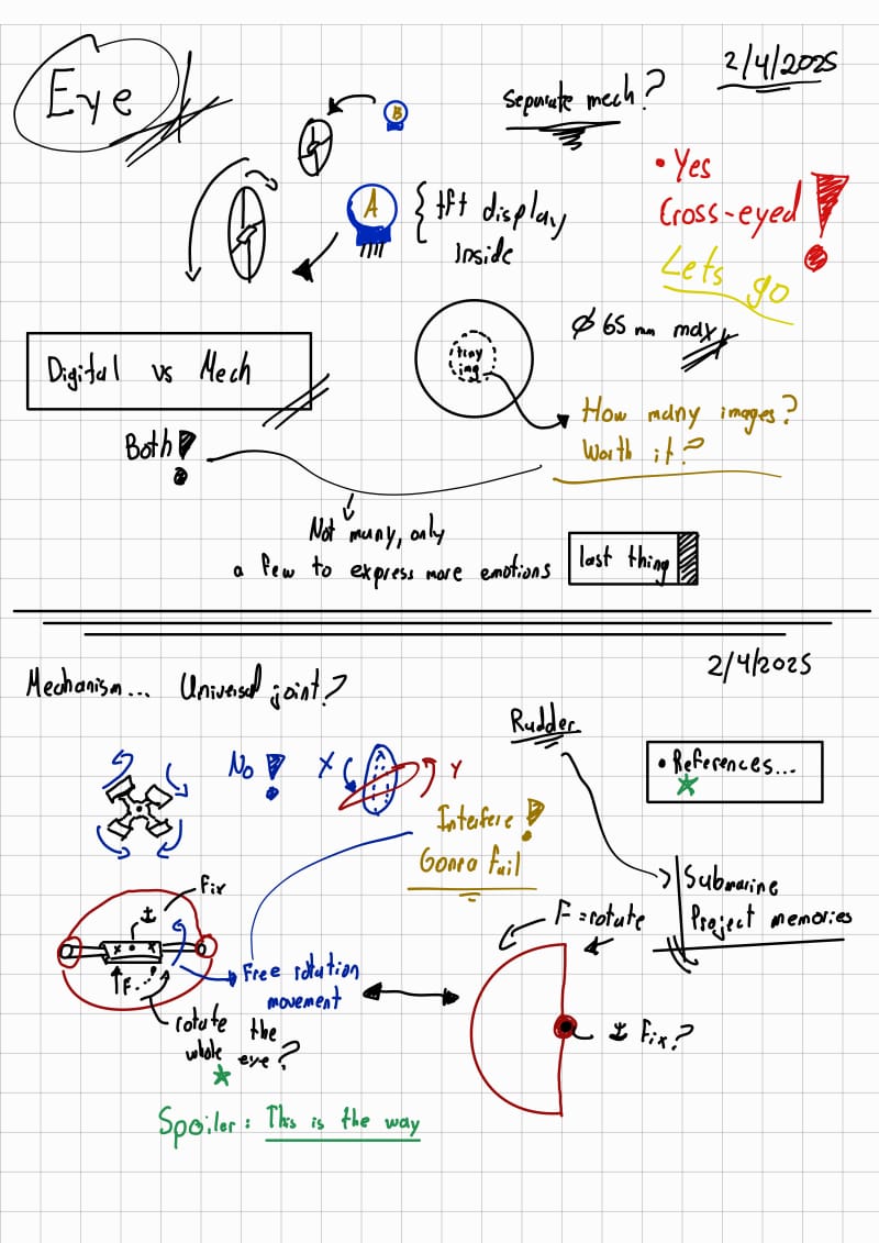
Eye mechanism and notes
The main idea is that by means of pressfit I can “put the eye control and the TFT” inside another piece that serves as the eyeball.
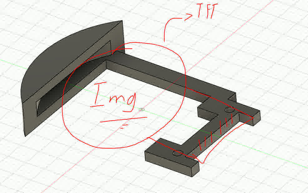
Main idea to incorporate the eye rudder to serve as a support for the tft display too2_compressed
Adapter for uniform pressfit
Final idea
2_compressed.jpg)
Main idea of the rudder control (Free mobility)
I printed the components using PLA with 15% infill, as the parts didn’t require high strength.
The eyeslids!
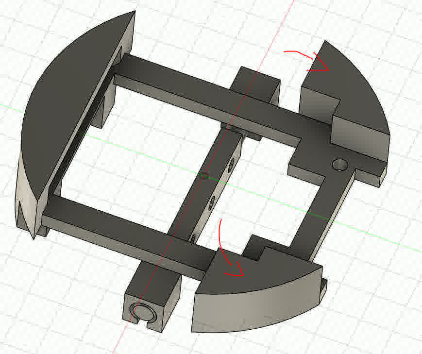
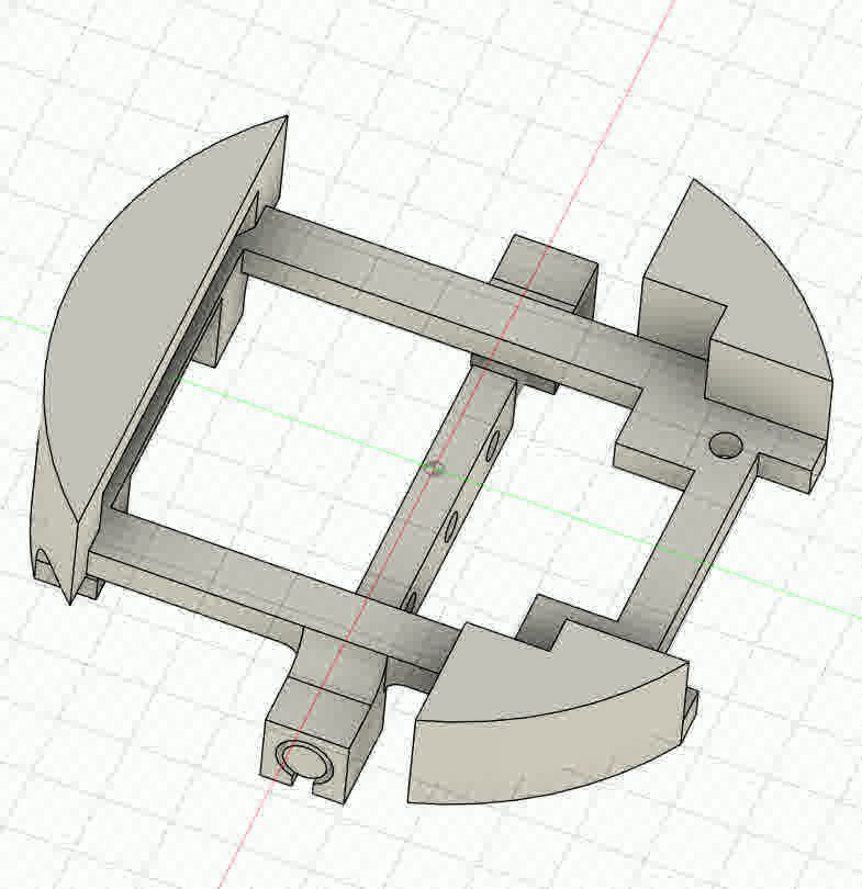
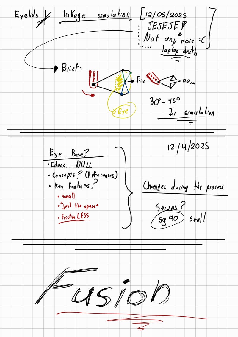
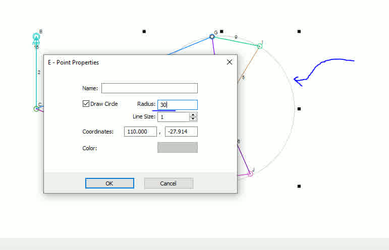
For eyelid actuation, I wanted a minimal energy footprint. Some designs use two servos per eye, while others control a single large eyelid. I opted for a single-servo linkage mechanism that could independently move both eyelids. I used Linkage software to simulate and measure the geometry needed. I'll run the simulation again... That's what I get for not saving it in the cloud (spolier).
New Sketches!
Eyelids sketch
Adapter for uniform pressfit
Main idea for the eyelids
Mirror replication
Servo base?
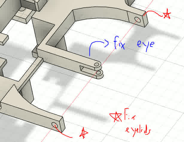
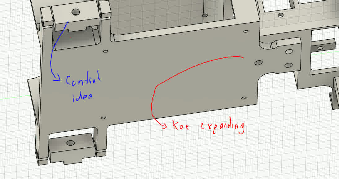
Assembling the servos proved tricky. I didn’t start with a fully planned design—instead, I adapted and iterated. The result was somewhat chaotic, but it allowed me to accommodate servo conflicts and placement issues in real time. The base for the servos came together organically through testing and adjustment.
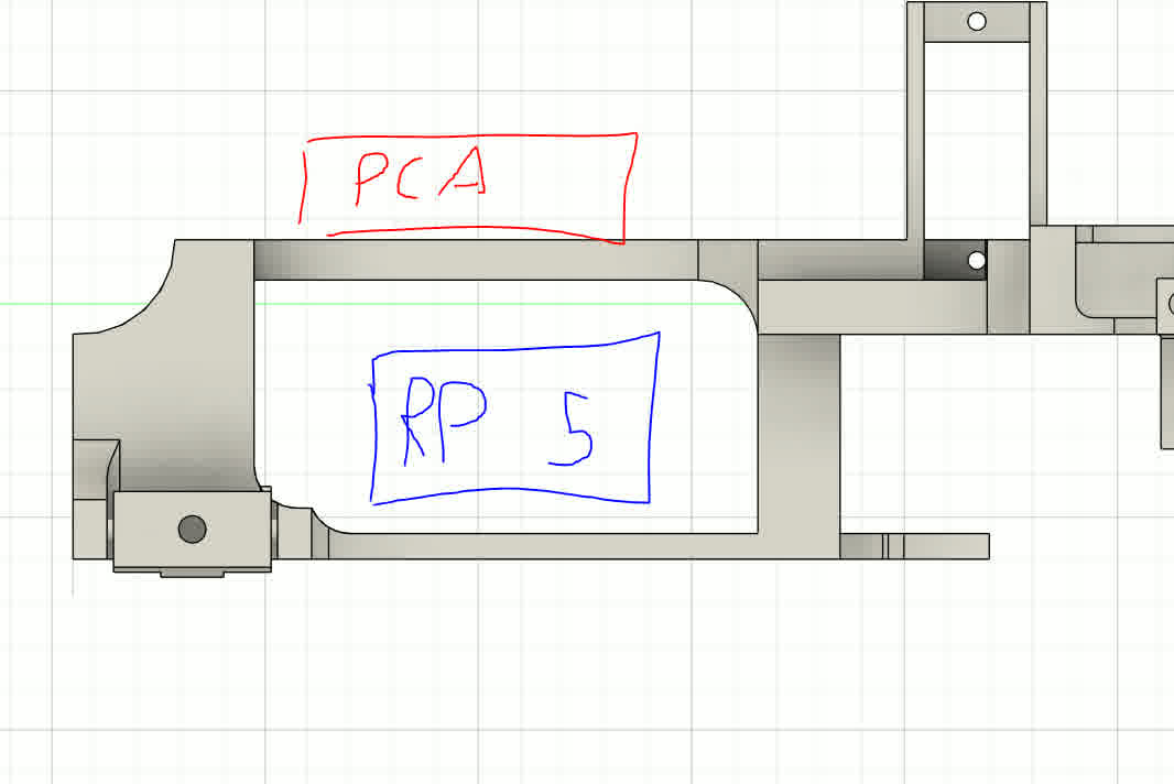
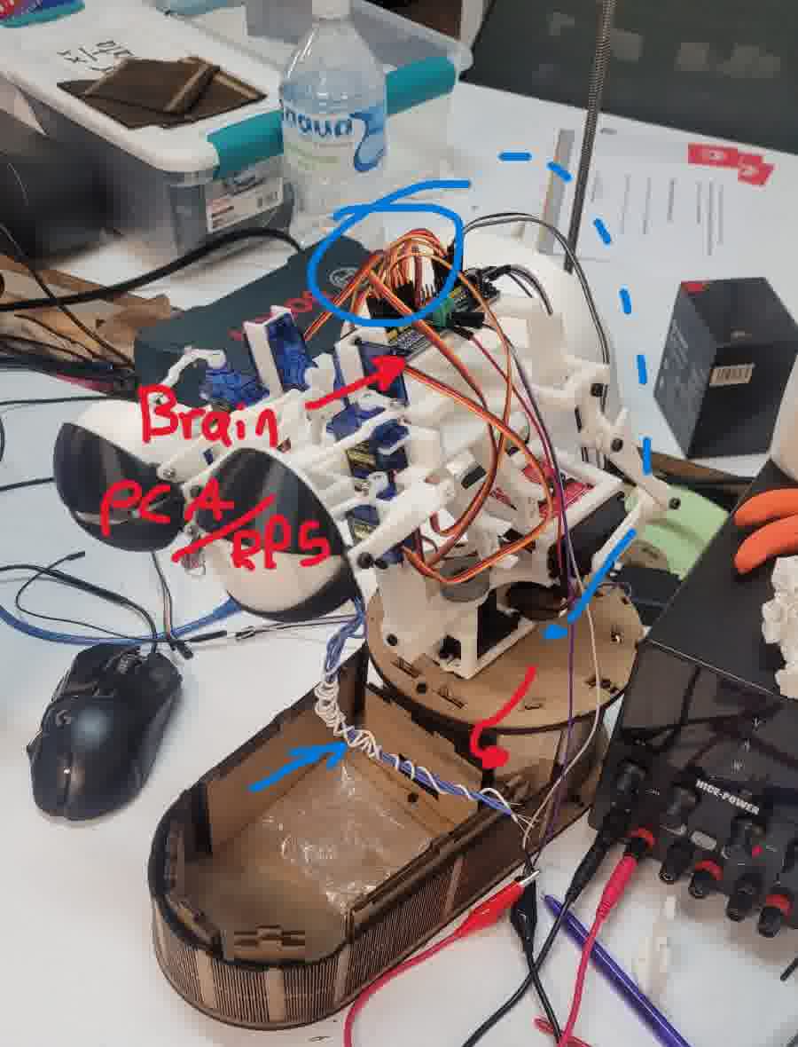
Always while designing my mind was thinking beyond and I was already thinking, what's next? So I had already estimated a moderate amount of servo motors. So, controlling them all from a single microcontroller would be impractical. The PWM generation and interrupts would overwhelm most microcontrollers. Therefore, I integrated a PCA9685 servo controller to offload the processing and ensure reliable timing.
This led to another idea: since a head needs a brain, why not embed the “brain” within the head itself? My servo controller became the neural hub. For eye tracking and reactive motion, I wanted to implement AI-based recognition via camera input. I previously worked with MediaPipe to animate tentacles in another animatronic project, and I considered using it again. However, real-time AI processing requires significant computational resources.
Even lightweight AI models, like those trained with Edge Impulse, proved too demanding for a microcontroller. I didn’t want the animatronic tethered to my PC, so I integrated a Raspberry Pi 5 into the head as a dedicated onboard processor. This allows me to use Bluetooth or Wi-Fi to communicate with the system locally. I designed a dedicated mounting area for the Pi within the eye mechanism to ensure compact integration.
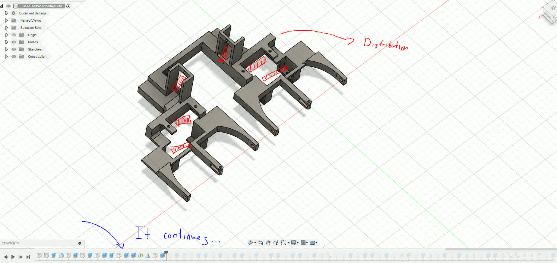
Distribution and chaotic timeline.
Electronic brain control consideration.
References and design, the neck!
New Sketches!
Neck sketch
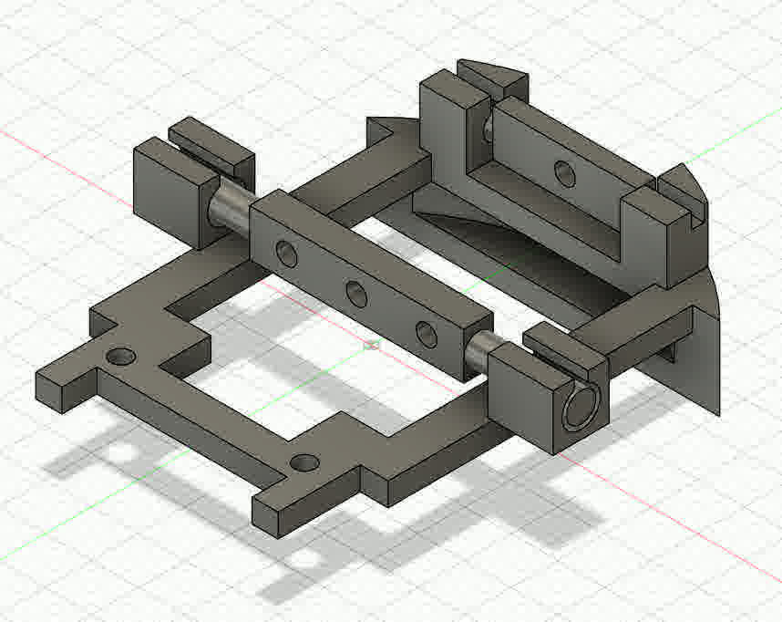
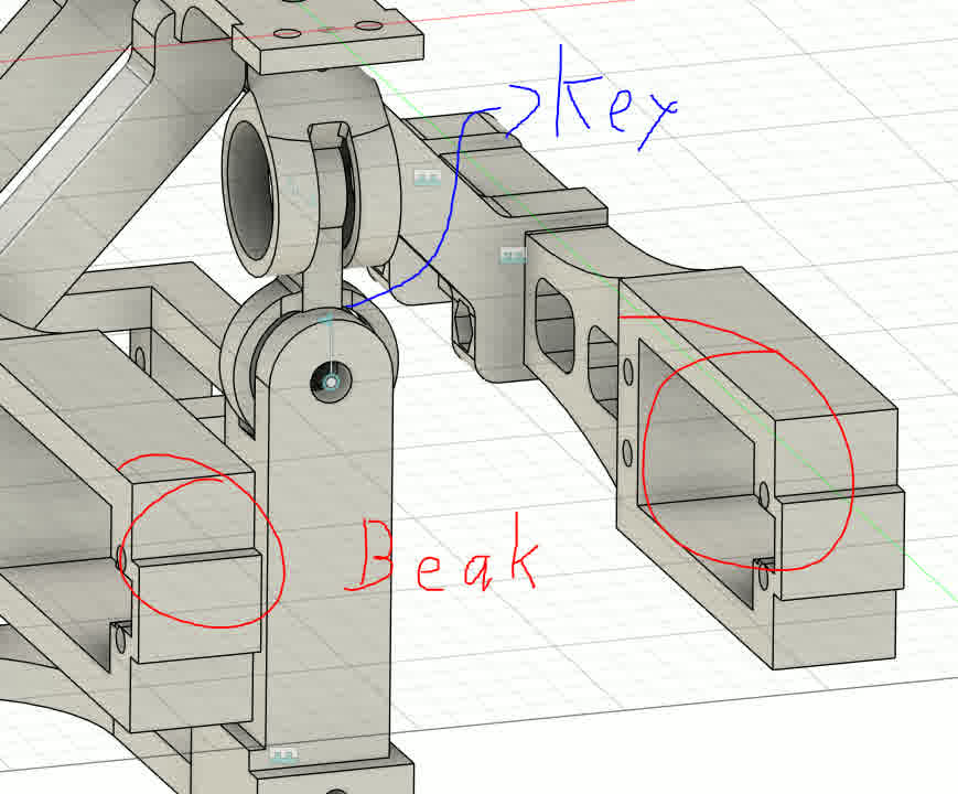
Next came the neck. I needed a robust, three-degree-of-freedom system capable of supporting the weight of the entire head. To achieve smooth motion, I used bearings to reduce friction. I custom-designed all parts in Fusion 360, building the mechanism to withstand up to 10 kg based on simulation data. All parts were assembled in a single Fusion file for simplicity.
Some info of the neck
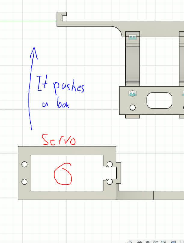
Servo actuator
Initially, I planned to place the rotational servo at the edge of the base for better torque leverage. However, this significantly increased the overall footprint of the head. Instead, I embedded the servo directly beneath the neck, creating a more compact and balanced design. I printed this structure with 40% infill to support the added weight.
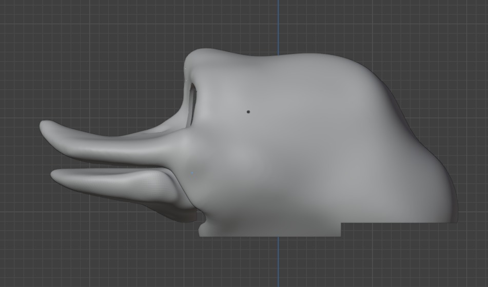
With the neck completed, I moved on to the beak. My design philosophy here focused on balancing strength and lightness. The lower beak, which moves, needed to be durable. I printed the core structure in PLA with 15% infill and designed it to support additional components and mounting features. I also began modeling aesthetic features using Blender, to give the animatronic a more expressive, lifelike appearance.
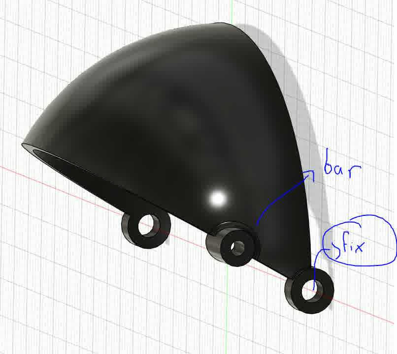
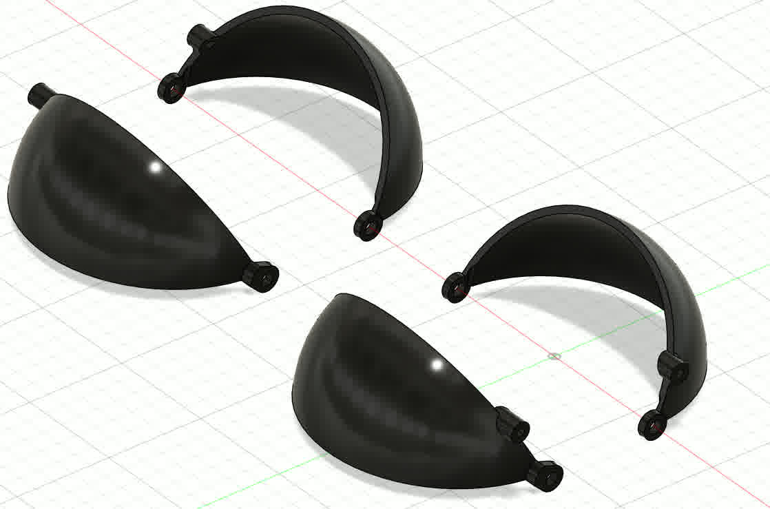
Also, here are the bars for the servomotors and some parts that will be used to connect the exoskeleton to the housing. For the measurement of the rods I actually used a prototype assembly to take into account how everything was looking.
Here is the final assembly in Fusion360.
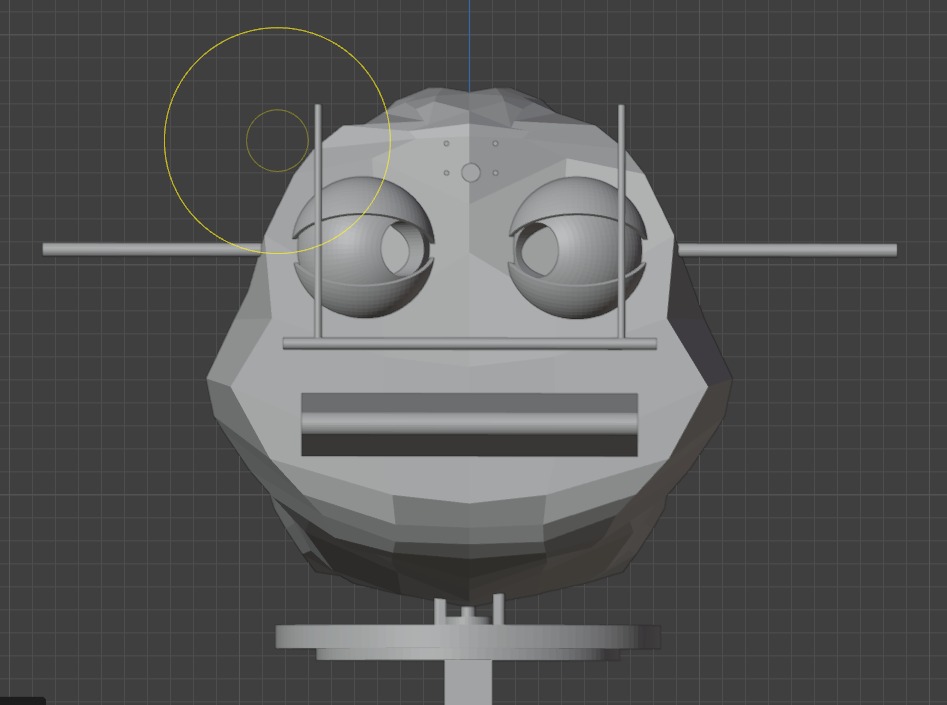
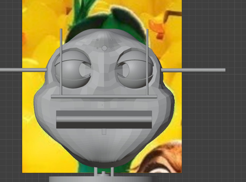
Blender time!!
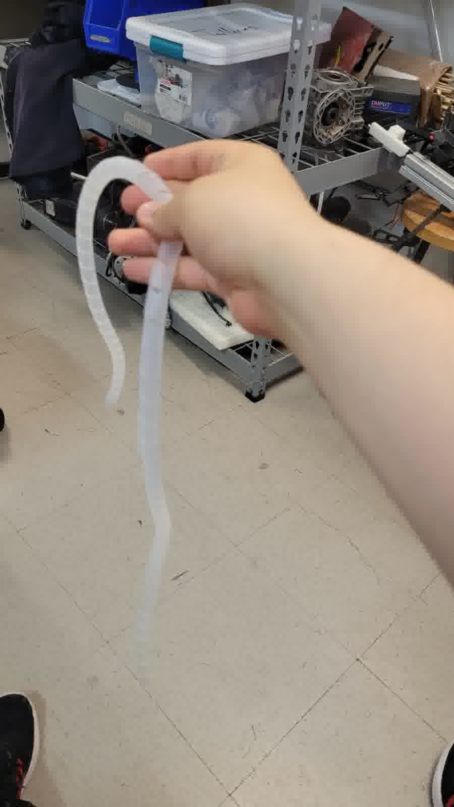
I experimented with ideas for the outer casing and skin of the animatronic. Inspired by animatronic characters like “Walt el pato animatrónico”, I plan to design a flexible mask, possibly cast in silicone or FlexFoam. The outer casing would act as the skull, and the flexible covering as the skin. The design is still in progress, but in my free time I am exploring new ways to sculpt the surface using digital models and physical molds (this include clay, gypsum, fiberglass and silicone).
As for Blender, the truth is I have no idea how to even use it. I tried the program once at the beginning of FabAcademy, but honestly, I got lost quickly. I could only follow tutorials, but I couldn't do anything on my own. Then, in Week 5, I tried to pick it up again. This time, I understood more things, but many functions were still unclear to me. However, that week, I found that if I was going to try design in Blender, it would be with the sculpting tools. It's not that these tools are easier, more practical, or simpler to use; in fact, the process can be either very lengthy or very, very quick, depending on your skill as a sculptor (literally speaking). But honestly, these tools were easier for me to understand due to their simpler interface.
From here, while I could explain in detail how to use everything in Blender, sometimes even I don't get it. I would just recommend that, to sculpt, you start with a cube and apply 1 to 2 subdivisions at the beginning to start shaping from very basic polygons. This, in addition to making it easier to manage the mesh when it gets more complex, also helps prevent issues like the mesh breaking. So, the main brush I used to shape everything was "Grab." In theory, it's like working in "Edit Mode," as the brush literally moves the points. Therefore, even though this mesh might seem risky, it's actually the best, since it's genuinely molding the mesh.
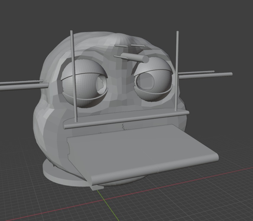
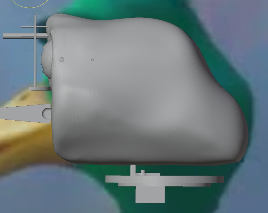
Finally, what’s left is to make passes, take a coffee, and maybe look at some reference images. In my case, this took a while. The main issue with Blender is that, without a good addon, it's really complicated to make parametric shapes. So, making the casing wasn't an aesthetic challenge, but a geometric one. My solution was to assemble my animatronic with the greatest considerations possible, then bring it into Blender to create a shape closer to something real that I needed. To do this, I also made some protrusions in the areas where my animatronic needs holes to assemble the casing (screws). This is because the best tool I found to make cuts in Blender was the boolean operations. With these, you literally choose which element you want to combine, cut, or just take the intersection between them. This helped a lot. Then, to go from mesh to solid, I simply used the "Solidify" option, which literally adds another mesh and joins them to create a "thickness."
First poly
First poly another perspective
Second poly
Second poly another perspective
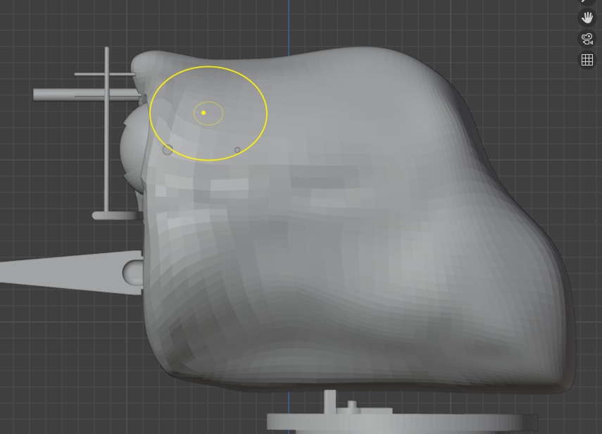
Better finishing and started to use some references
A more defined shape 1
A more defined shape 2
.jpeg)
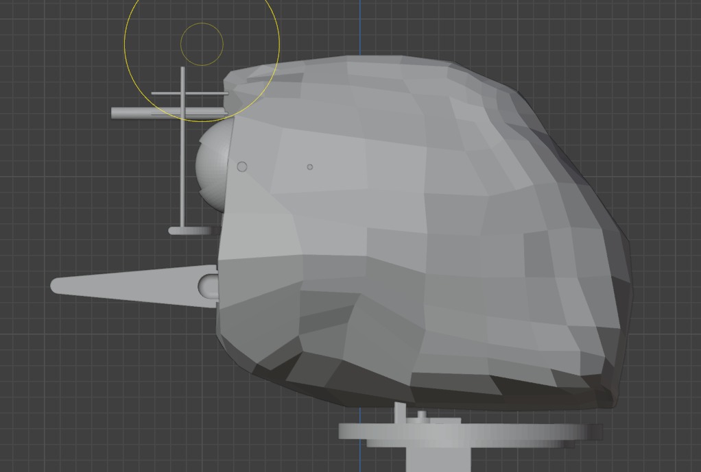
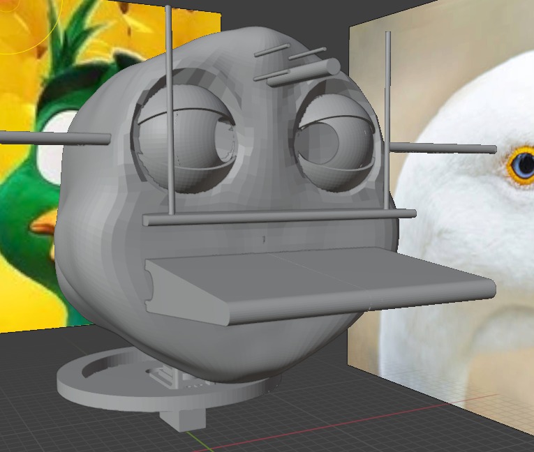
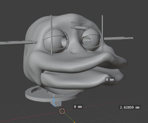
Third poly and starts to look great (Bread appereance)
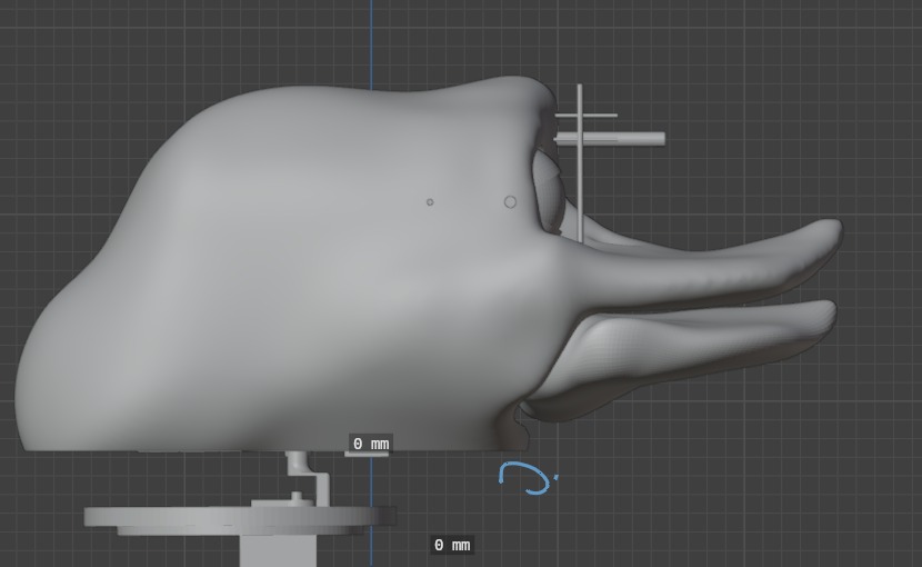
Side view
.jpeg)
Eyes cutterd with boolean operation (also the holes of the assembly prevoiusly planned)
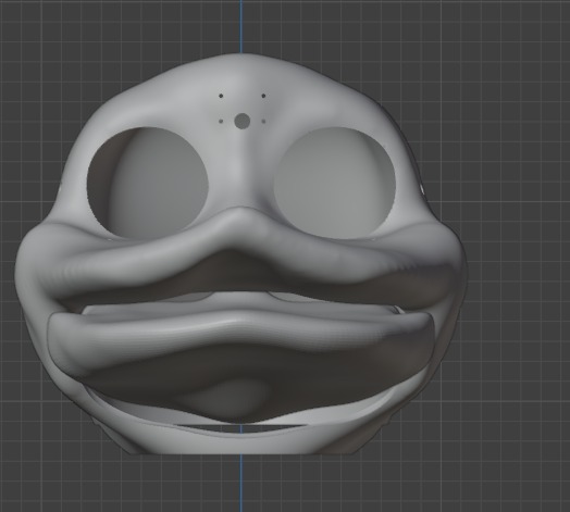
Now we are talking
Side view 2
All together
Results and some funny tests
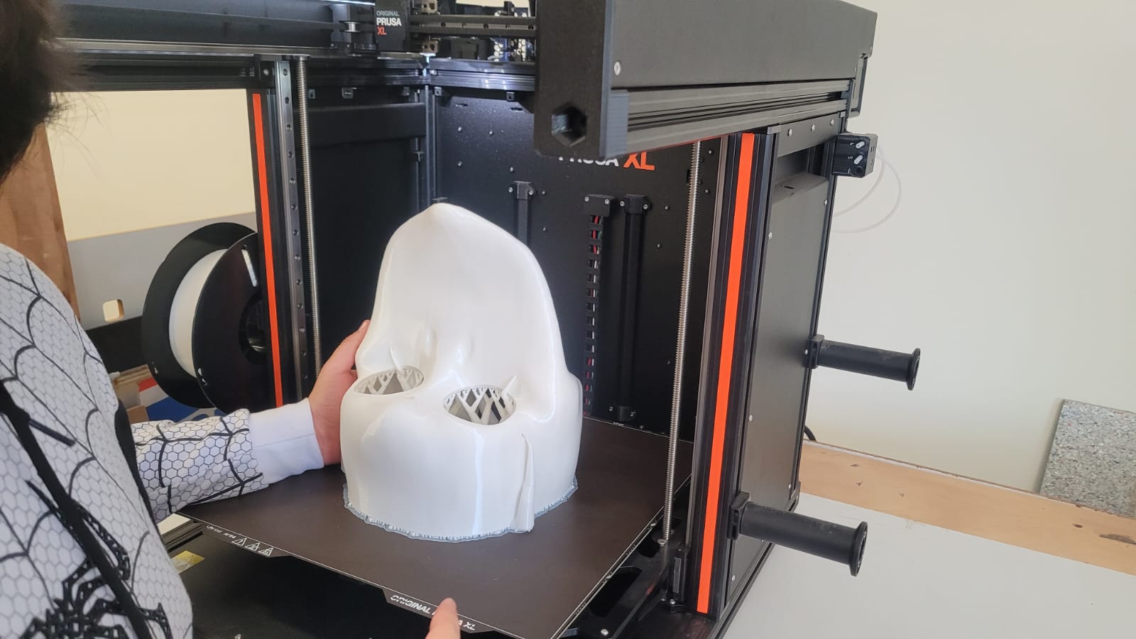
3D printing results
Results
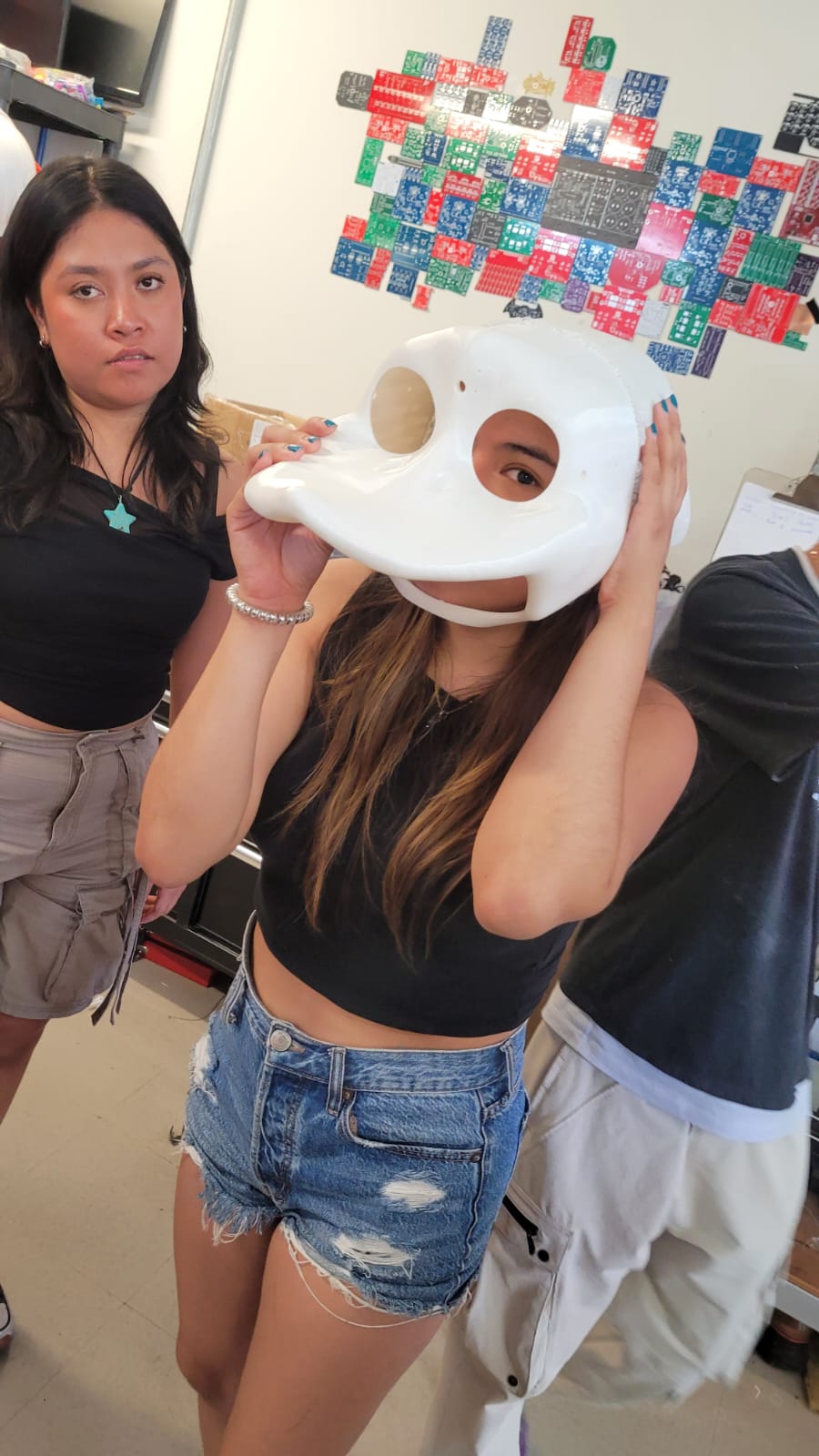
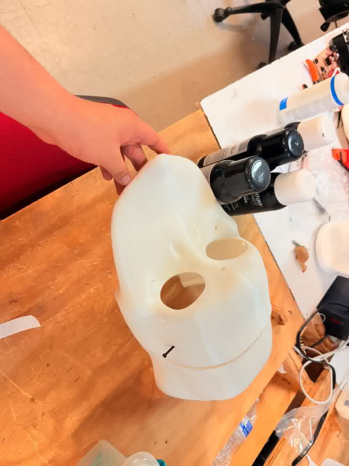
Literally everyone try to put it on
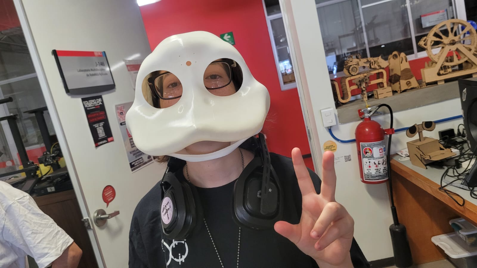
Xavi the mask
Now, hear me out... It's 8 PM, everything's going smoothly. My casing works, I was almost done with the code, and... Blue screen.
Well, no problem. The error was due to overheating, according to the message that popped up. I decided to wait for it to cool down and turned it back on. After 20 minutes, it was cool, and everything seemed fine. It started up correctly, so I started finishing the code... Blue screen. From there on, every time I tried to do something, it sent me to the BIOS, and I couldn't leave there no matter what.
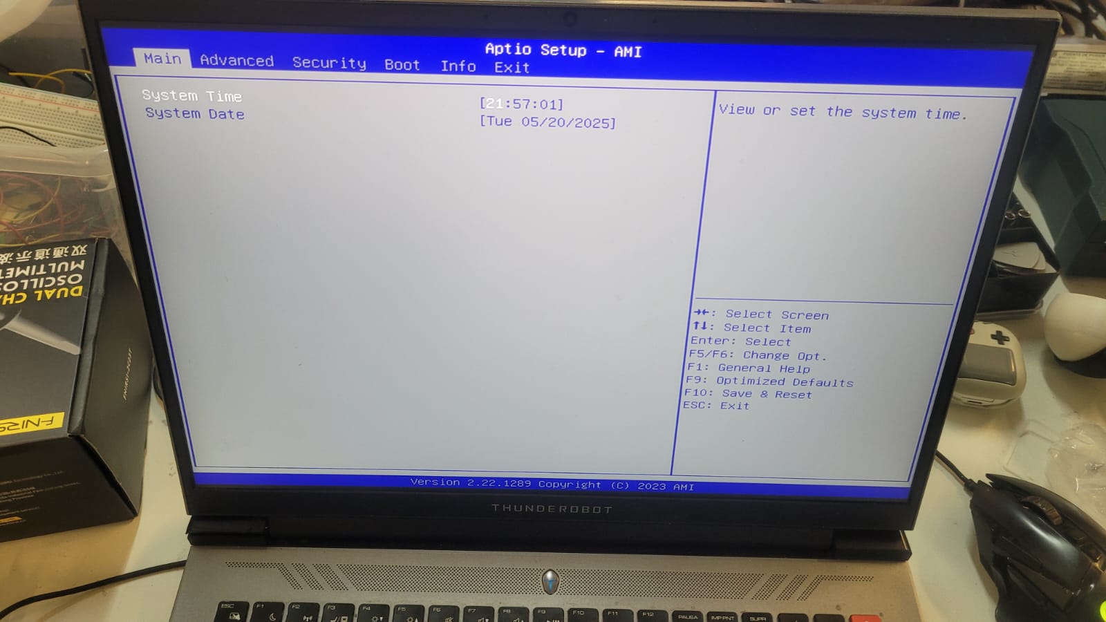
Bios only
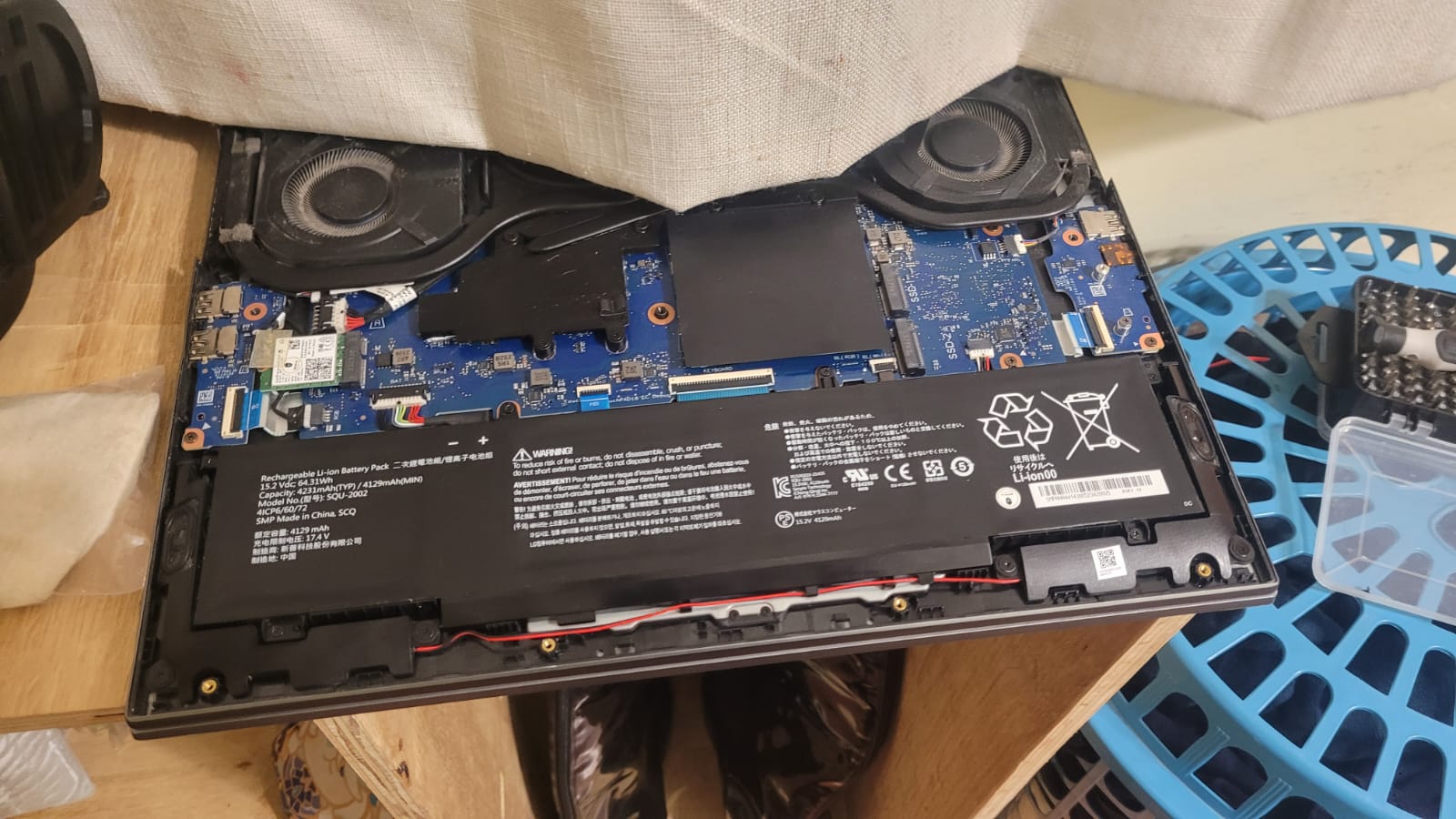
Bye bye warranty
SSD death
At least we tried
Thanks, Apolinar, for staying up with me trying to revive it, but unfortunately, the memory died completely. The SSD practically stopped responding, not even to another PC. And while we might not be able to recover the data with our technical skills, the truth is that getting it repaired is too expensive. Plus, given the time I have available, I need to get my computer back to keep working. So, at least for me, I considered the memory dead, stored it in an anti-static bag, and Apolinar lent me one from his desktop PC. So, I pretty much lost all the data I had worked on that day: my casing models in Blender (thank God I sent them to print just before), and many others that, honestly, I hadn't uploaded to the repository because I forgot... lesson clearly learned.
So, what now? Give up? I pretty much lost a lot of files from some assignments and many things that took me a long time to complete. Or maybe...
Well, even though I wanted to make an edit of me working through all the files I lost in a time-lapse for the laughs, it actually took me longer than expected, and I wasn’t in the best mood—I just wanted to get it over with xD
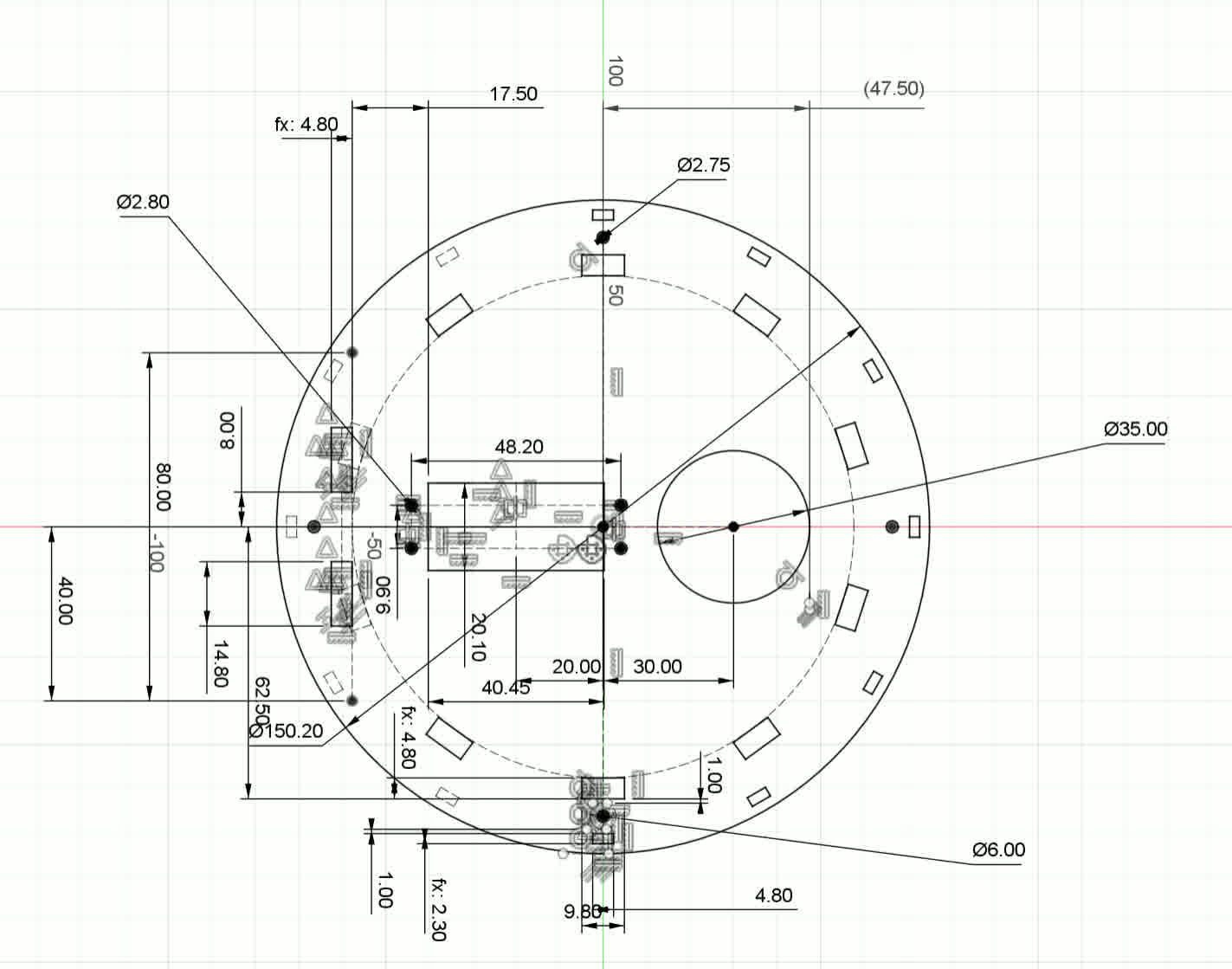
MDF structural base
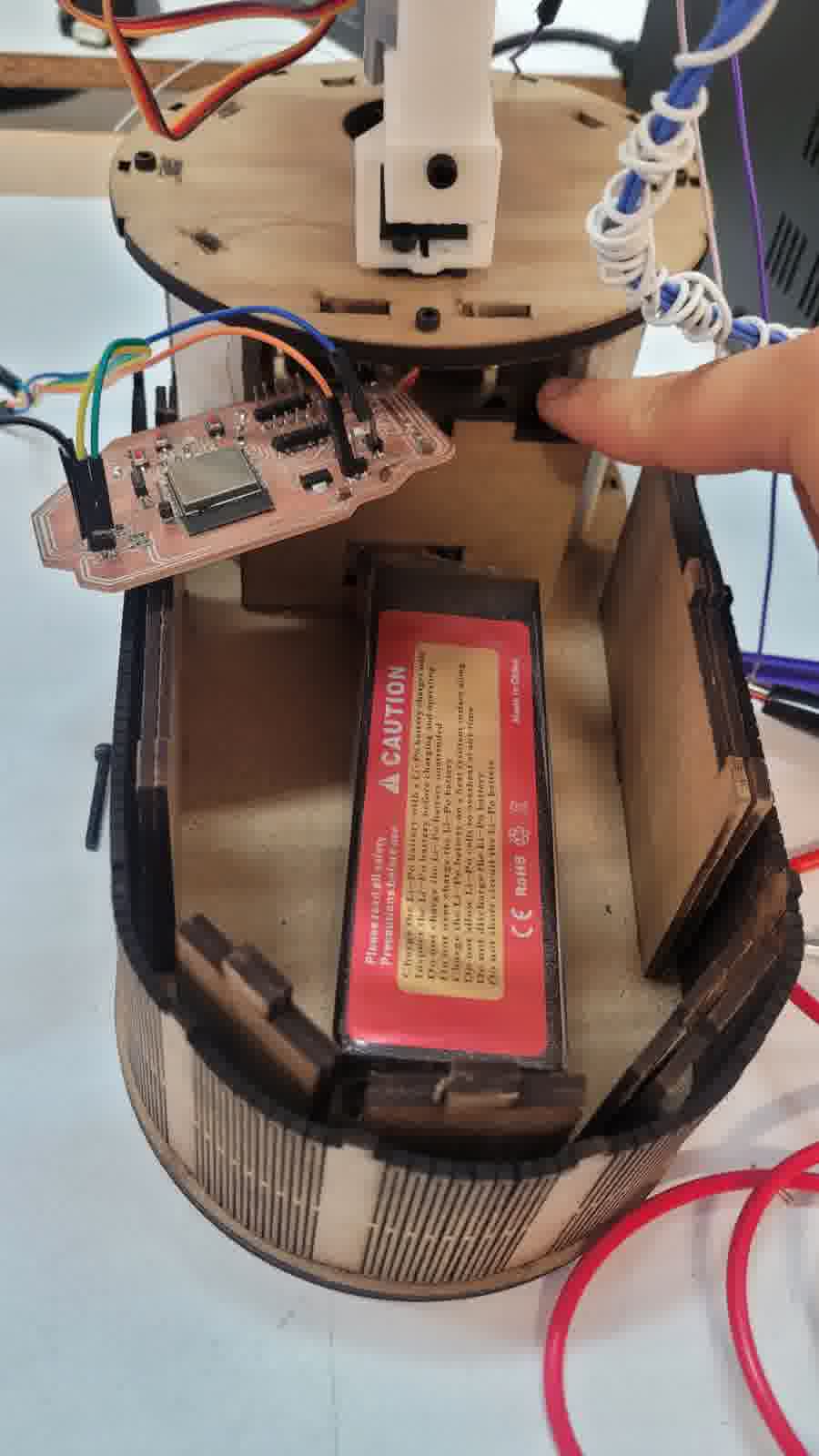
For the MDF base, I simply wanted to create a shape that wasn't the traditional rectangular box. I aimed for something more curved, so I decided to make a solid structure of 5 mm (in the lab, we only have MDF of 2.5 mm or 3 mm, so I envisioned combining two 2.5 mm plates to achieve the necessary thickness). This, along with a 2.5 mm sheet that surrounds the "box" to give it a more curved appearance. At this point, I just let my creative freedom take over, and I only considered measurements for the LiPo battery and the ESP32 board created in Week 8.
Maybe not as simple as I thought
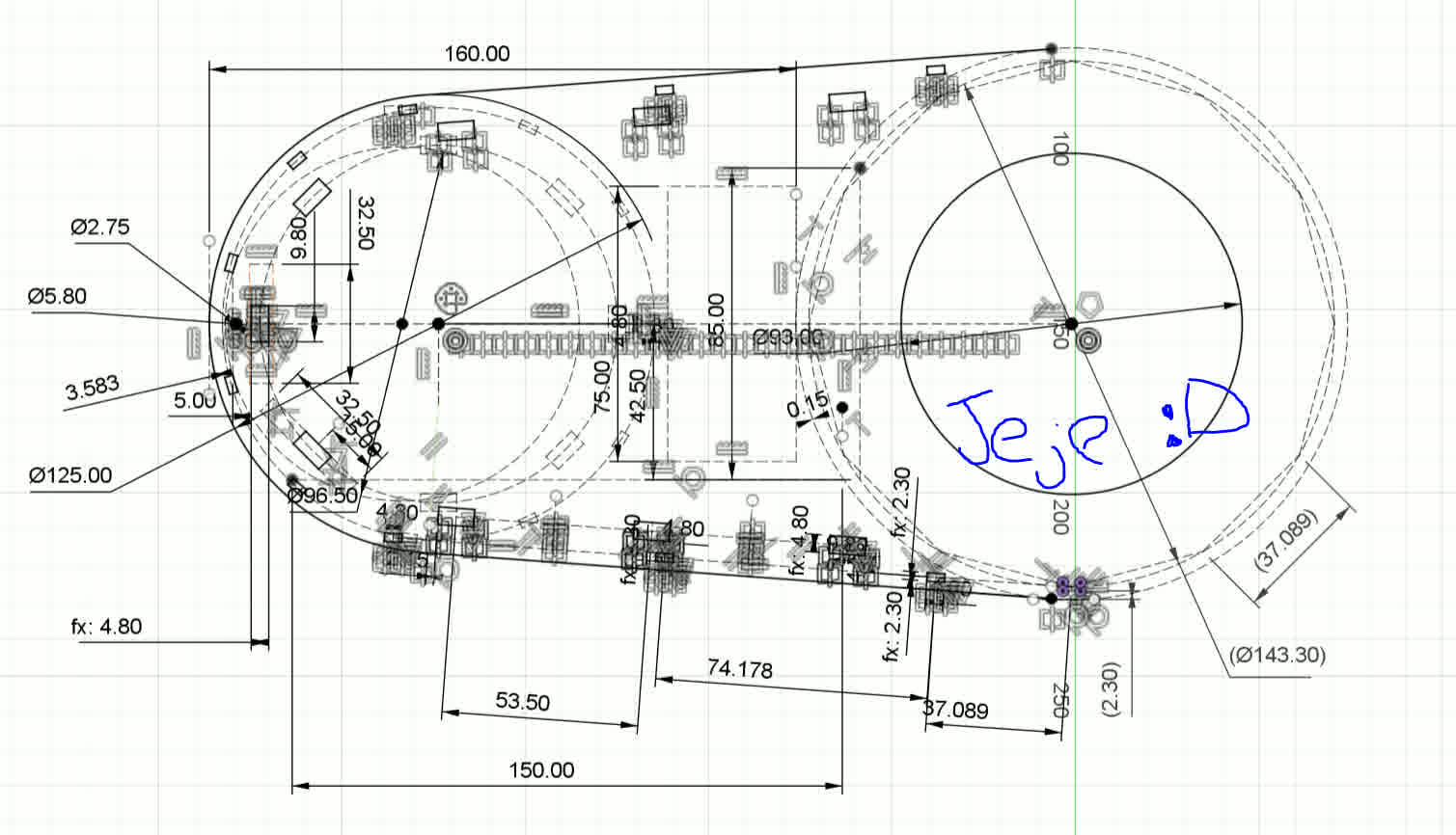
I may exaggerate with the measurements
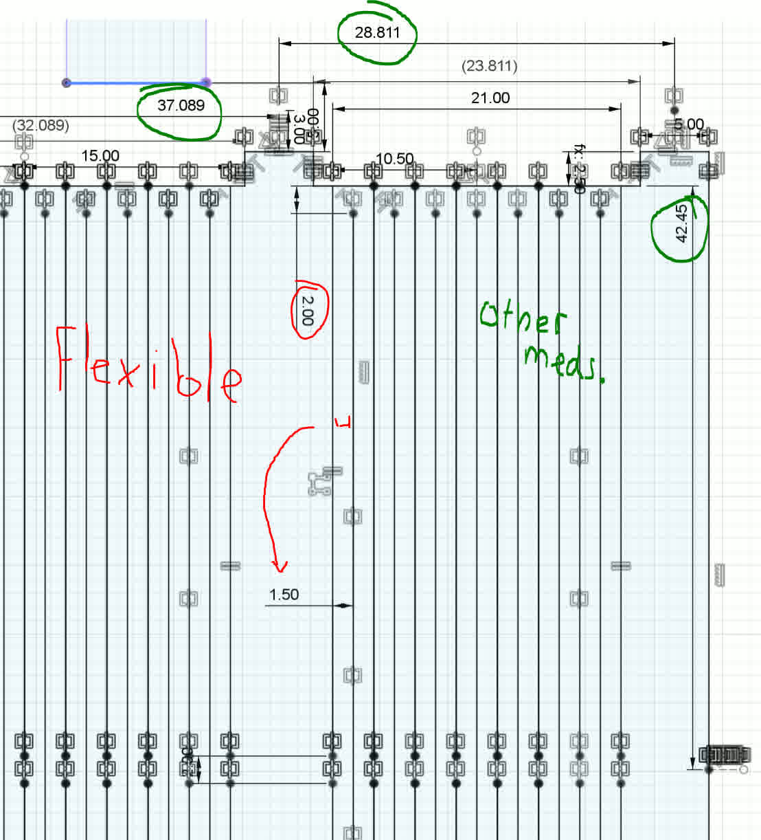
Flexible measurements
Electronics
As mentioned earlier, for the electronics, I will use the board developed in Week 8. The truth is, I wanted to design another PCB, but it’s not necessary. I really only need my microcontroller with enough pins to connect the TFTs via SPI. Therefore, I just need to connect the module to control the drivers via I2C. The connection to the laptop can be either wireless, thanks to the ESP32, or via UART on the ESP32, either with my laptop or later with my Raspberry Pi. The camera is literally available on either of the two computers (my laptop or the Raspberry Pi with the Raspberry Pi Camera Module 2). So, as much as I wanted to create another board (because I truly want to, I enjoyed soldering and I find it relaxing), the truth is, I don’t need it. It's redundant.
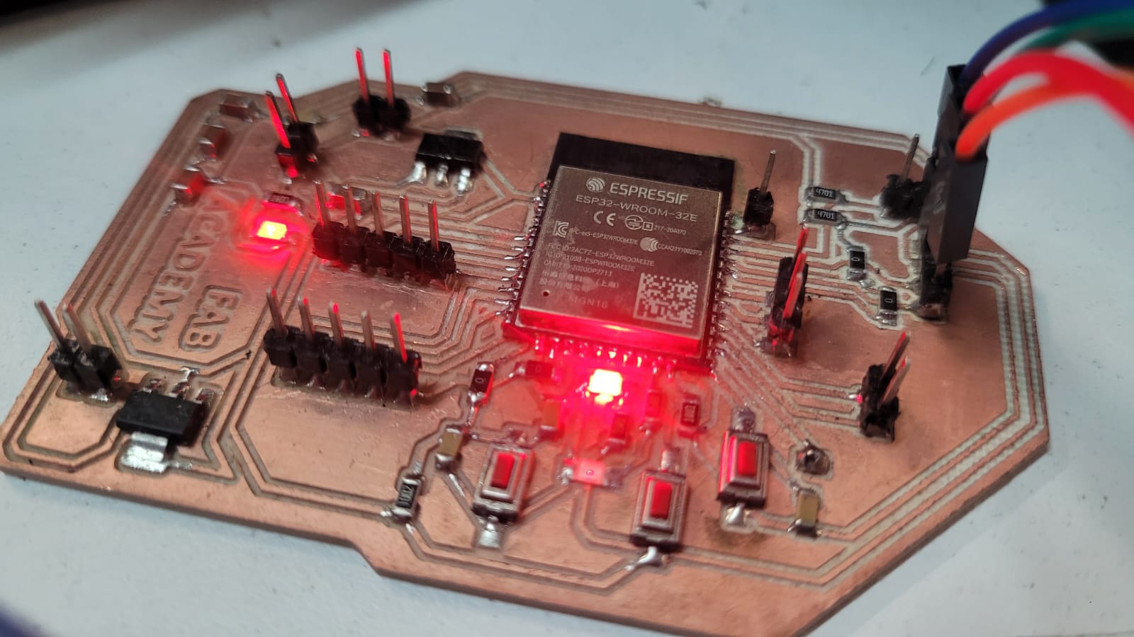
ESP32 Pingu-board
CODE
As for the code, it follows a simple logic; it literally just needs to track the person’s movement by considering the position of their nose at that precise moment. Regarding the servos for the eyes, they need to be reserved for small movements, so there needs to be a threshold large enough to ensure they only move when the person makes slight adjustments. However, for the neck movements, these servos do need to have a higher threshold. This threshold will be estimated during testing. Also, due to the nature of the mechanisms that don’t allow some servos to move their full 180°, the code itself has to establish limits to ensure they never exceed the specified parameter. Although this was simulated during assembly, it needs to be verified during testing, so the values are subject to those results.
Beyond that, the code remains simple. It communicates with the computer, which, in turn, sends data to it. But this only happens when the microcontroller needs it. This follows an ACK and NAK system. Therefore, the logic for entering the code must be non-blocking. This ensures smooth servo movement, proper communication with the computer, and the images shown on the TFTs.
ESP32 Control
--------------------------------------------------------------------------------------------------------------------------------
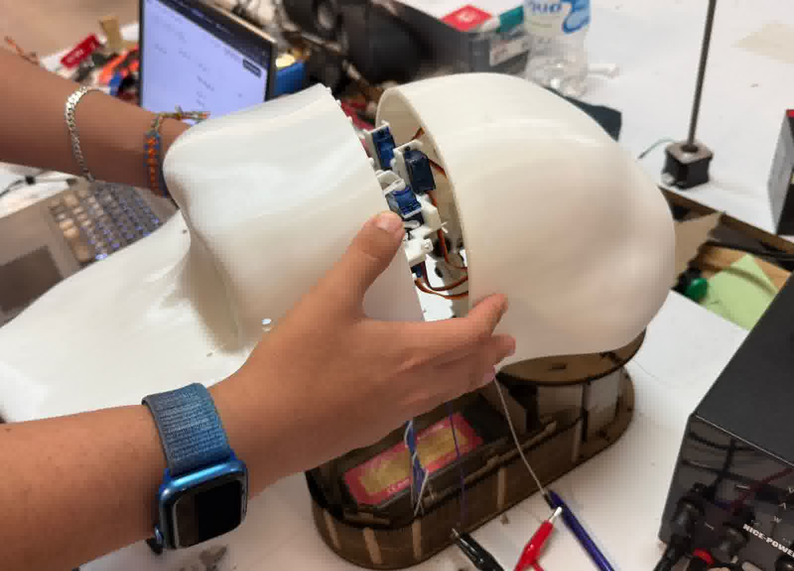
System integration
The design and assembly of the key animatronic mechanisms (eyes, eyelids, neck, and beak) followed a logical sequence. Starting with designing individual mechanisms using 2D and 3D CAD tools, then thinking about how each interferes with the other, and finally, designing a compact and self-contained base for the actuators and bars. Notably Fusion360 for mechanical design and Blender for sculpting the outer head case to provide an aesthetically pleasing finish. The animatronic head case fully encloses these mechanisms, protecting the components and unifying the system into a single cohesive unit. The base, fabricated from 2.5 mm thick MDF provides structural support for the entire assembly, with all PCBs and components securely mounted both within the head case and on the base itself. Also, almost the entire base is made up of two MDF boards placed side by side. So, the actual thickness is 5 mm.
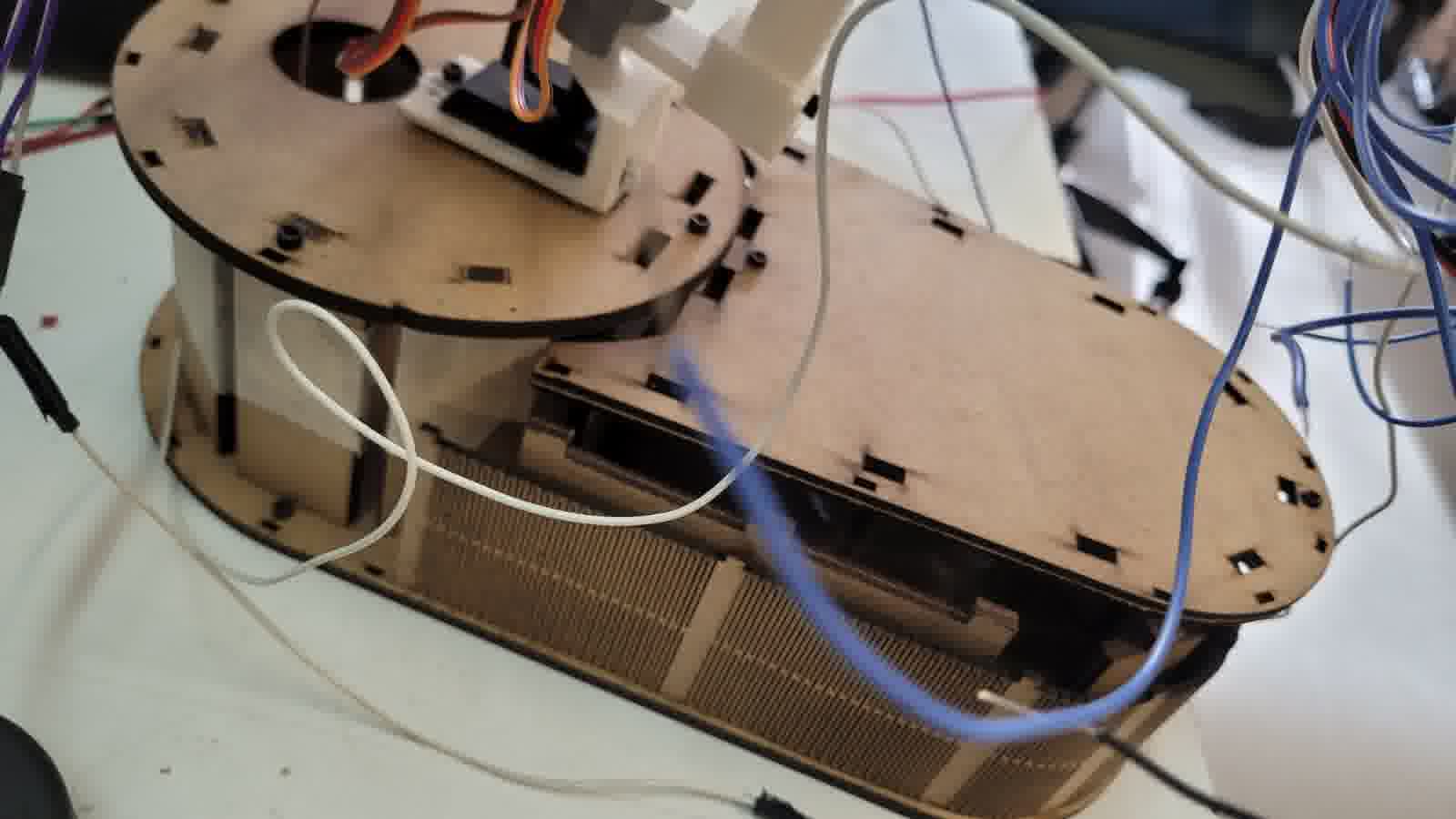
My own wood covering
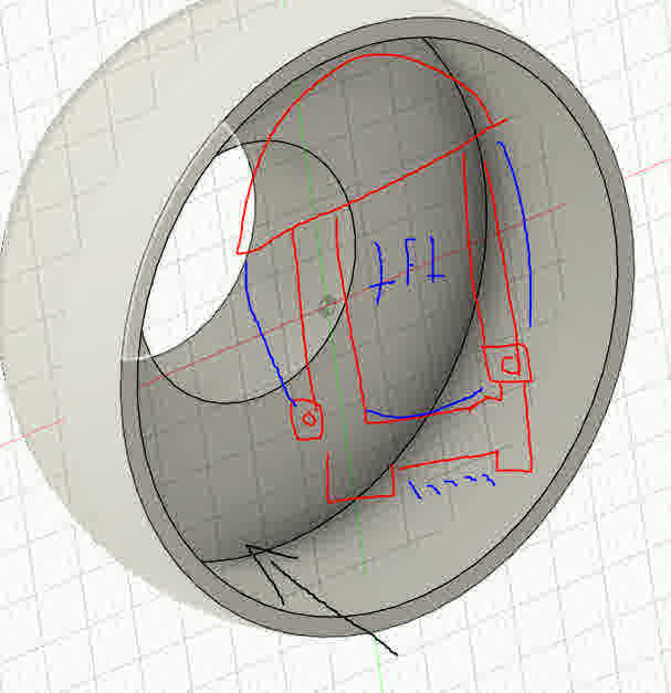
Perfect space for the tft, they are not even noticed
For the electronic integration, it focuses on the custom ESP32 microcontroller board interfacing with actuators and sensors. Integral to the animatronic’s expressiveness are the two 1.28" 240x240 pixel round TFT displays (GC9A01), which serve as dynamic eyes. These displays render high-resolution, smooth eye animations synchronized with the mechanical movements, providing enhanced visual feedback beyond purely mechanical actuation.
Designated space for the microcontroller and for the battery
Servo actuation is managed through a dedicated PCA9685 PWM driver module, allowing precise, non-blocking control of multiple servomotors. This hardware abstraction simplifies signal generation for up to 11 servos, ensuring smooth and coordinated movements of the eyes, eyelids, neck, and beak mechanisms without burdening the microcontroller’s processing capabilities.
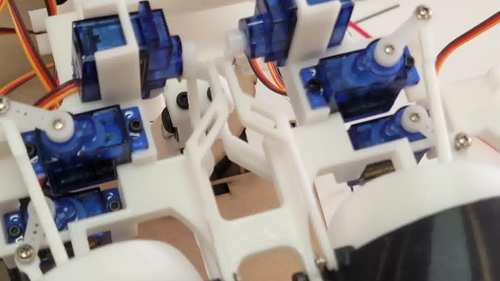
Arrangement of servomotors
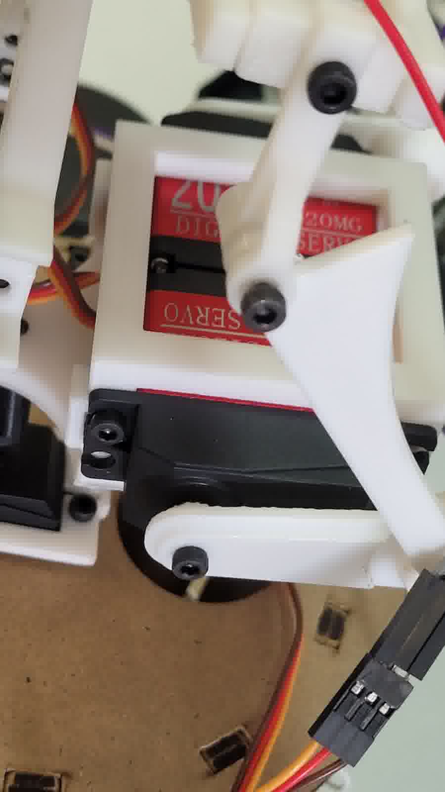
Arrangement of servomotors 2
Wiring is carefully covered by soldering or connecting with proper headers and connectors (Duo-point). Wiring is routed neatly inside the head case and base, with cable management enhanced using plastic zip ties to secure cables, improving both reliability and aesthetics. All wiring is organized to avoid conflicts with moving parts, ensuring smooth operation and ease of maintenance.
Cable management
Cable to cover cables
In addition, I am implementing computer vision system using MediaPipe AI running on an external PC, which processes camera input to track human movement. The AI model generates tracking data sent to the embedded microcontroller via a communication protocol based on acknowledgment (Ack) and negative acknowledgment (Nack) for reliable data transfer. The camera interface draws a real-time figure of the person being tracked, enabling the animatronic to follow the movement fluidly.
Camera integration
Likewise, the goal is to integrate a computer as the brain inside the animatronic. That is, a Raspberry Pi 5 with its corresponding camera to process the MediaPipe model. My own laptop already does this, but this will be incorporated for a more discreet integration of the electronics.
For its part, both the raspberry pi 5 and its respective camera already have spaces designed for its incorporation either inside the housing of the face, as well as for the raspberry pi 5 has a special space under the module that controls the servos.
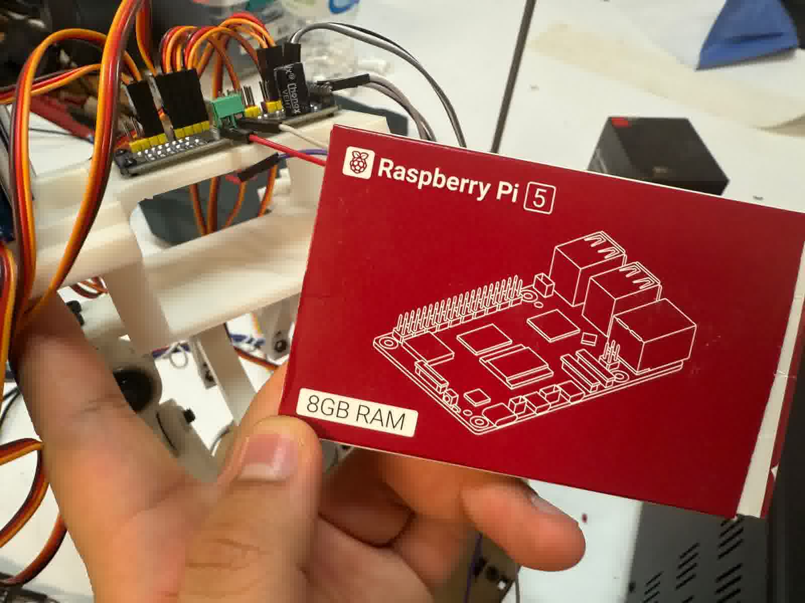
Space dedicated to the Raspberry pi 5
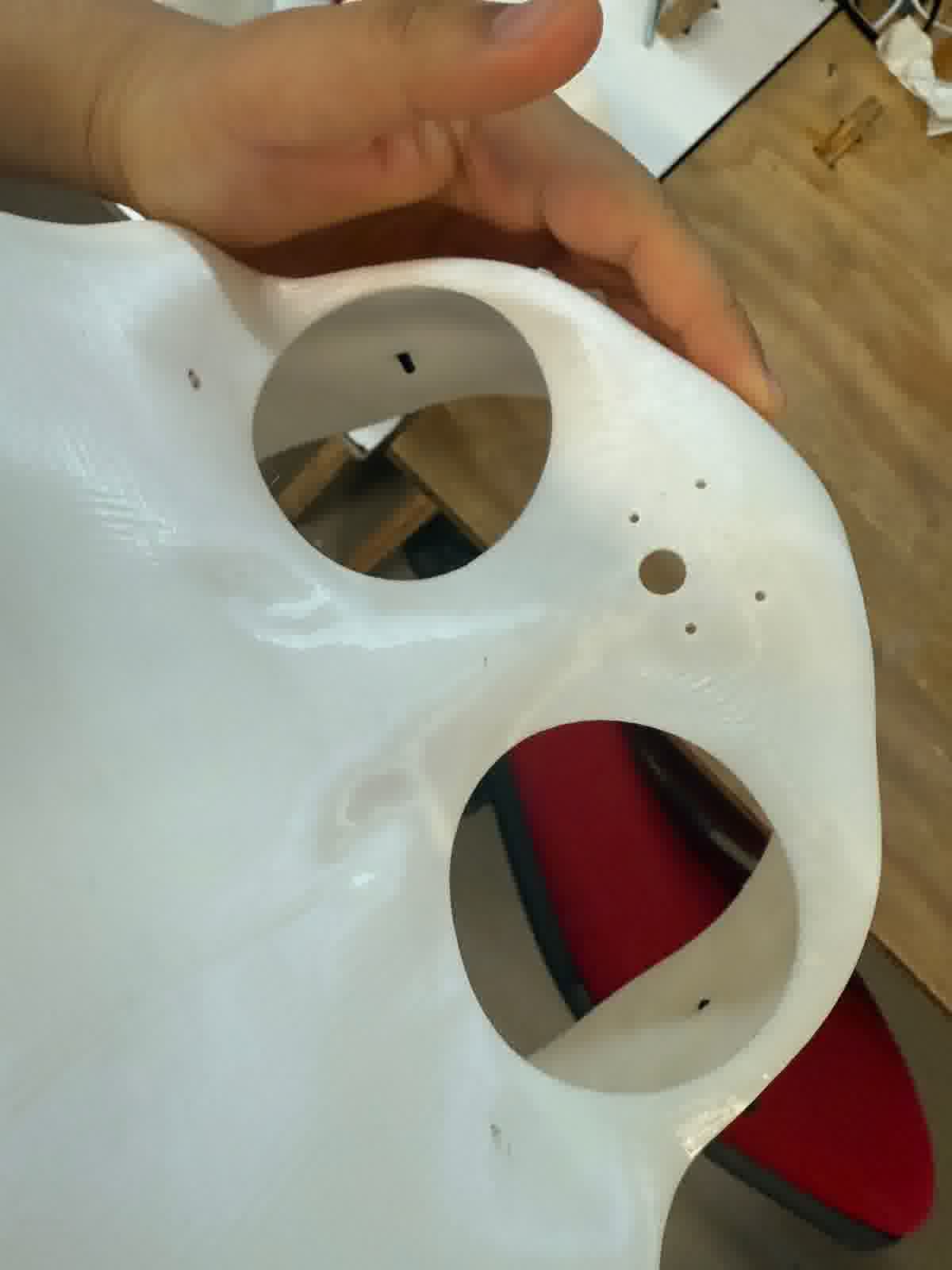
Cover case face
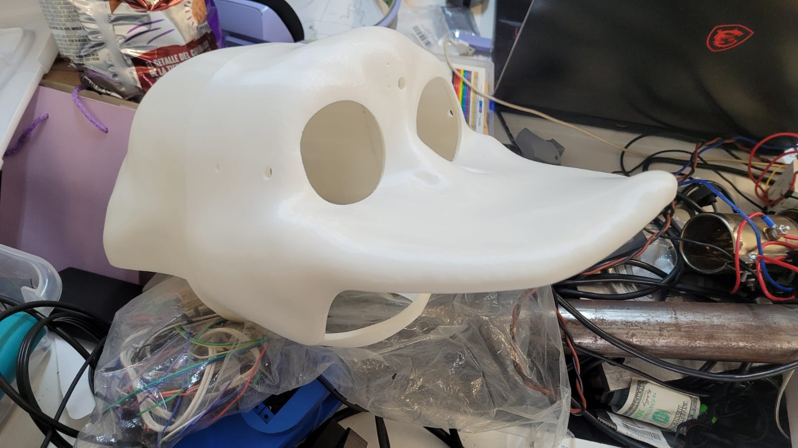
Now I am talking about it, all PCBs, actuators, and components are securely mounted in dedicated places inside the head case and on the MDF base. This organized packaging prevents damage and facilitates assembly and maintenance. The sculpted head case provides a polished, finished look that conceals cables and mechanisms, resulting in a product that appears professional and complete. Also since it is sculpted in Blender is visually pleasing. As well as, given that at the beginning of the sculpting in blender I based my own assembly made in fusion to have more realistic measurements with respect to the whole exoskeleton.
Finished product appereance
--------------------------------------------------------------------------------------------------------------------------------
Aplications and implications...
What will it do?
My project will create an animatronic head that naturally and smoothly tracks a person’s movements. Using MediaPipe for face recognition of the people, the animatronic will coordinate eye, eyelid, neck, and beak movements to engage viewers in a realistic and compelling way.
Who has done what beforehand?
I researched numerous animatronic projects, click to see my references: Eyes and Neck, focusing on head and eye mechanisms. While many references helped shape my understanding, every mechanical design, electronic integration, and system implementation is my own original work, inspired but not copied.
What will you design?
I will design all mechanical subsystems from scratch — eyes, eyelids, neck, and beak — along with the structural MDF base and the external head case sculpted in Blender. The electronics involve a custom ESP32 PCB with neatly routed internal wiring for a clean, integrated system.
What materials and components will be used?
The mechanical parts are mostly 3D printed in PLA, mounted on a 2.5 mm MDF base. SG90/MG90S, MG996R and TD-8120MG servos will handle actuation via a PCA9685 driver that ensures smooth, synchronized movement. Two round 1.28" GC9A01 TFT displays provide dynamic eye animation, fully integrated within the head. Also, it is thought to implement a raspberry with its respective camera to replace a laptop and integrate in a better way the whole project.
Where will they come from?
Mechanical materials come from the Fablab or are fabricated directly by me. I will buy the electronic components because I also want to have these for personal use.
How much will they cost?
Materials
| Category | Item | Price |
|---|---|---|
| Mechanical Materials | PLA Filament (1 kg spool) | $23.63 - Based on PrusaSlicer |
| Mechanical Materials | MDF Sheets, 2.5 mm thickness | - |
| Mechanical Materials | Screws M3 (various lengths: 25 mm, 12 mm, 10 mm, 8 mm, 4 mm) | AliExpress |
| Mechanical Materials | Screws M2 (lengths: 5 mm, 8 mm) | - |
| Mechanical Materials | Screws M5 (length: 25 mm) | - |
| Mechanical Materials | 625ZZ Bearings - 3 units | AliExpress - $4.7 |
| Electronic Components | 1.28” Round TFT Displays (GC9A01) - 2 units | AliExpress - $6.22 |
| Electronic Components | PCA9685 PWM Servo Driver Module - 1 unit | AliExpress - $3.52 |
| Electronic Components | Micro Servos (SG90/MG90S) - 6 units | AliExpress - $26.32 |
| Electronic Components | High-Torque Servos (MG996R) - 2 units | AliExpress - $24.51 |
| Electronic Components | High-Torque Servos (TD-8120MG) - 3 units | AliExpress - $21.06 |
| Additional Hardware | Raspberry Pi 5 - 1 unit | AliExpress - $165.24 |
| Additional Hardware | Raspberry Pi Camera Module v2 - 1 unit | AliExpress - $15.57 |
| Additional Hardware | LiPo Battery 11.1 V, 5500 mAh - 1 unit | Amazon Mexico - $61.40 |
| Additional Hardware | 5V, 5A Power Supply - 1 unit | AliExpress - $7.75 |
| Electronic Components | ESP32 WROOM 32E - 1 unit | Digikey - $5.38 |
| Electronic Components | 4.7k Resistor (1206) - 2 units | - |
| Electronic Components | 0 Resistor (1206) - 4 units | - |
| Electronic Components | 75 Resistor (1206) - 2 units | - |
| Electronic Components | 1k Resistor (1206) - 1 unit | - |
| Electronic Components | 160 Resistor - 1 unit | - |
| Electronic Components | 1206 Tactile Button - 3 units | - |
| Electronic Components | 1206 LED - 3 units | - |
| Electronic Components | 47uF Capacitor (1206) - 4 units | - |
| Electronic Components | 22uF Capacitor (1206) - 4 units | - |
| Electronic Components | AMS1117-3.3 Voltage Regulator - 1 unit | Digikey - $0.27 |
| Electronic Components | AMS1117-5 Voltage Regulator - 1 unit | Digikey - $0.12 |
| Electronic Components | Male Pins - 28 units | - |
What parts and systems will be made?
I fabricate every mechanical linkage and actuator mount for eyes, eyelids, neck, and beak, plus the external casing via 3D printing. The electronics, including the custom ESP32 PCB and PCA9685 servo controller, are assembled and programmed by me.
What processes will be used?
The project combines additive manufacturing (3D printing in PLA) with subtractive techniques (laser cutting MDF and milling PCBs). Electronics are soldered by hand with care, and embedded software is developed for real-time servo control and AI communication.
What questions need to be answered?
I need to confirm that mechanical movements are smooth and reliable already with the entire system integrated, and that the final assembly looks cohesive and professional. Actually, I emphasize that I need to UNIFY all the parts of my project. Separately or partially assembled it works perfectly.
Basically, I need to do more tests with the lipo battery or with my plug-in voltage source, not with the labs power supply. Also, I still need to test everything with the raspberry pi 5 instead of my computer for the AI model. And do many more tests with the entire casing.
How will it be evaluated?
Evaluation will consider tracking accuracy/responsiveness, motion smoothness and good looking appearance and communication reliability. Subjective impressions of lifelike quality and engagement will also be important, as well as how well the project meets initial goals and overcomes challenges.
What has been done so far? (Done/remain comparative)
I have designed and fabricated the main mechanical subsystems and completed simulations in Fusion360 and in real life. The MDF base is built and stable. The head shell is sculpted in Blender and already printed. The embedded code for AI communication and servo control is functional, with initial tests showing promising results.
Regarding the creation of parts, code or electronics, everything is done. About the final finish, it already has a decent appearence, but if I have time I can improve the look by painting the parts that are pure aesthetics.
Therefore, I literally only have to unify things for testing, possible error detection and correction. Throughout my tests I have only found the possible failure for the SG90 servo motors, therefore, to ensure the proper functioning of everything I will change them for better servos of the same size (MG90S), as well as sanding some areas to avoid frictional stress.
What works and what doesn’t?
Mechanisms for neck and beak work reliably with fluid motion. The AI system tracks poses well, sending commands without loss. However, SG90 servos (eye mechanism) occasionally struggle with torque on eye actuation, causing minor inconsistencies.
This is a minor detail, because the truth is that if I do not say that this is due to a mechanical failure, it seems that it is programmed to move like this. This is because it gives a funny aspect. So in the worst case it is a minor detail.
Also, the head’s weight (~3 kg) limits portability, so it is mounted on a base, not as a “wearable”. The MDF base needs reinforcement to avoid disassembly from uneven loads.
What’s next to do? (What questions need to be resolved?)
I will unify all components inside the sculpted head case. I plan to change some SG90 servos for MG90S servos. I will reinforce the base structurally. I also intend to integrate a Raspberry Pi 5 for on board AI processing. I also have to integrate everything with my voltage sources, that is, I have to do tests with my lipo battery and my compact power supply. Not with the labs test power supply.
With the answer to this question I want to make it clear that I already have in mind everything I have to do or, better said, I already know “what I have to solve and especially how I am going to do it”.
What will happpen when?
- 03/06/2025: Finish documenting everything that does not have to do with the project.
- 04/06/2025: Change the servos, sanding mechanism and base estability corrections.
- 05/06/2025: Testing with rapsberry pi and its camera. TFT wires management begins and testing.
- 06/06/2025: Just in case fixing possible errors/Painting.
- 07/06/2025: Documenting my progress.
- 08/06/2025: Documenting my progress.
- 09/06/2025: Final tests and hot fixes (the last push)
- 10/06/2025: Video and Slide finished
- 11/06/2025: Just in case day…
- 12/06/2025: From zero to hero results…
What did you learn?
This project strengthened my skills in mechanical design and fast prototyping. I learned the importance of planning for integration early and gained confidence managing complex hardware-software coordination as well as gaining self-confidence in my designs. Beyond technical skills, I improved project management and overcame hesitation toward fabrication, embracing hands-on creation as essential.
With respect to the project, I gained more knowledge about the criteria to take into account when implementing a mechanism with rotational motion in both X and Y axes. So, a big part of the FabAcademy was devoted to explore most of the tools of Fusion360 and, above all, Blender. I even plan to spend more time on Blender because of its complexity.
--------------------------------------------------------------------------------------------------------------------------------
Intellectual property: Xavimatronic!
For my final project, Xavimatronic, I want to make it freely accessible to anyone interested in studying, referencing, or replicating it. This project is not a groundbreaking invention; rather, it is an animatronic inspired by the university’s mascot, Xavi the goose. The mechanisms and design are based on my own ideas, complemented by some references I explored (these references are documented throughout this page). While this is not a completely original concept, the implementation of the system is my own and can be further explored on various online forums and sources. My intention is to openly share the files, as I aim to assist others who are working on similar projects or those who wish to deepen their understanding of animatronics and AI/movement tracking systems.
As for the commercialization of Xavimatronic, this specific version of the project does not have any commercial aspirations. I have made the conscious decision to protect my work through a Creative Commons license, encouraging others to use and improve upon the design without any commercial restrictions. Here is their official page to register the project
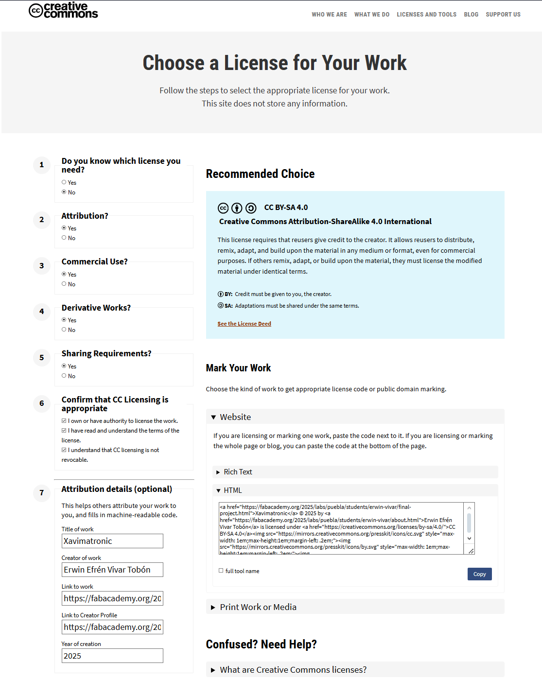
Creative Commons license.
This license requires users to give proper credit to the creator. It allows them to distribute, remix, adapt, and build upon the work in any medium or format, including for commercial purposes. Any modified material must be licensed under the same terms as the original.
Future Plans
As mentioned earlier, the current version of Xavimatronic is not aimed at generating profit or financial gain. However, with the support of my instructor and career coordinator, we are looking into developing a larger-scale version of the project. This will involve creating an upgraded version of the head, addressing any small design flaws or detail improvements. The plan is to build a more functional animatronic by integrating feedback from a larger team of engineers and designers.
Some specific areas we hope to improve include the "beak" mechanism, potentially replacing the current servomotor with a 4-bar linkage mechanism for better control. Additionally, a redesign of the head could provide more ergonomic and aesthetic improvements. Changing the materials used for some of the structural components might also help optimize the weight and durability of the system.
Looking ahead, the ultimate goal is to develop a fully bipedal animatronic that could assist in laboratory environments. The animatronic will incorporate a voice AI model and a database with information to help students with specific tasks and queries. The system will be fully movable, powered by its own battery source, allowing it to assist whenever needed.
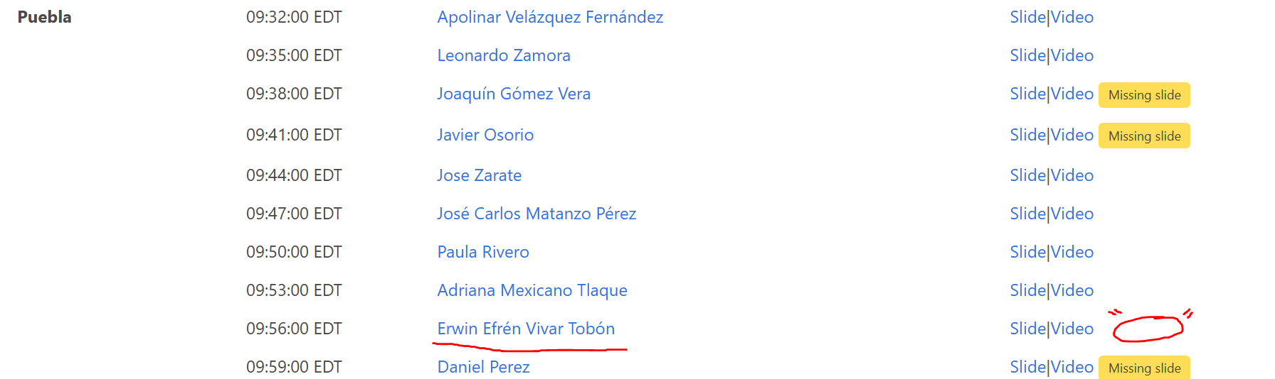
READY TO FIRE! I uploaded a draft of my final presentation slide and video.