Week 11
Networking and Communications
- Send a message between two projects
Networking and Communications
Networking and Communications
Communication protocols are rules that allow the exchange of information between devices connected to a network. Their goal is to enable devices to communicate with each other efficiently, securely, and reliably. Below are some of the most popular communication protocols in embedded systems.
INTRODUCTION
Communication protocols are rules that allow the exchange of information between devices connected to a network. Their goal is to enable devices to communicate with each other efficiently, securely, and reliably. Below are some of the most popular communication protocols in embedded systems.
I2C
I2C communication only uses two wires to transmit information between devices.
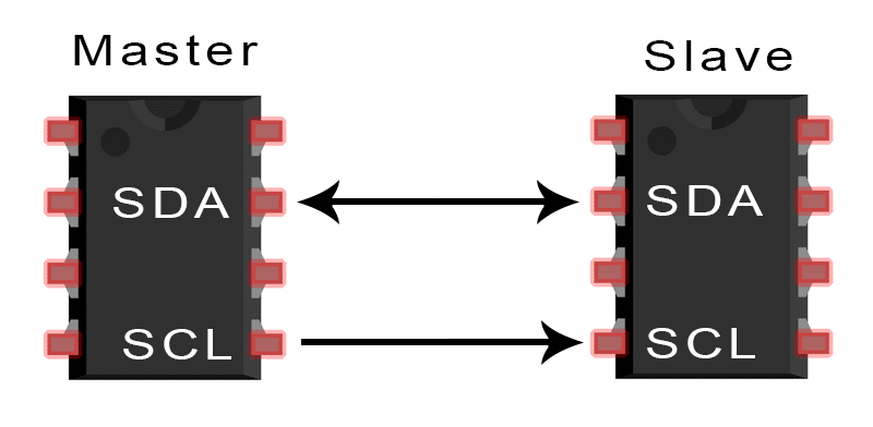
- SDA (Serial Data) - The line for the master and secondary to send and receive data.
- SCL (Serial Clock) - The line that carries the clock signal.
With I2C, data is transferred in messages. Messages are broken up into frames of data. Each message has an address frame that contains the binary address of the slave, and one or more data frames that contain the data being transmitted. The message also includes start and stop conditions, read/write bits, and ACK/NACK bits between each data frame:
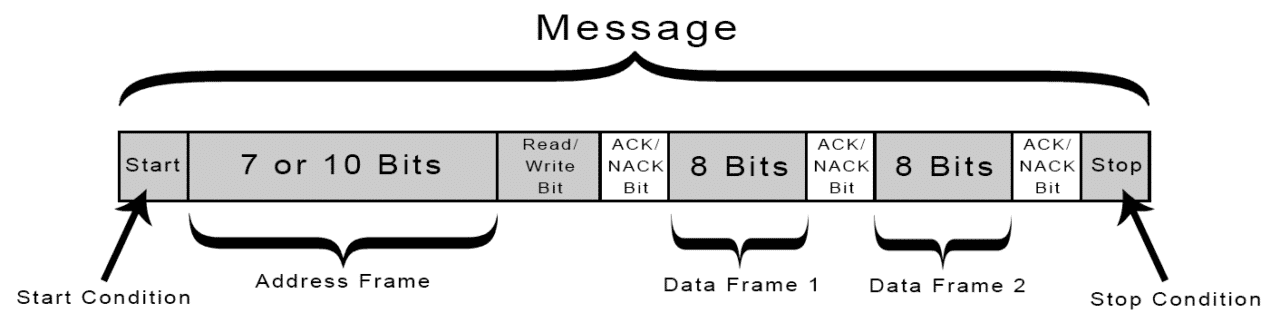
- Start Condition: The SDA line switches from a high voltage level to a low voltage level before the SCL line switches from high to low.
- Stop Condition: The SDA line switches from a low voltage level to a high voltage level after the SCL line switches from low to high.
- Address Frame: A 7 or 10 bit sequence unique to each slave that identifies the slave when the master wants to talk to it.
- Read/Write Bit: A single bit specifying whether the master is sending data to the slave (low voltage level) or requesting data from it (high voltage level).
- ACK/NACK Bit: Each frame in a message is followed by an acknowledge/no-acknowledge bit. If an address frame or data frame was successfully received, an ACK bit is returned to the sender from the receiving device.
SPI
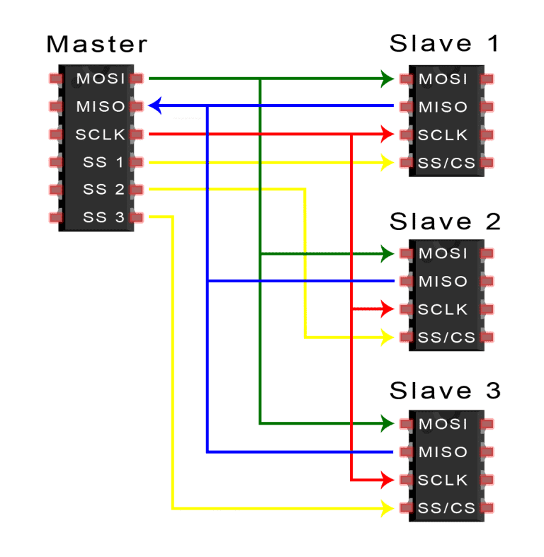
Devices communicating via SPI are in a master-secondary relationship. The master is the controlling device (usually a microcontroller), while the secondary (usually a sensor, display, or memory chip) takes instruction from the master. The simplest configuration of SPI is a single master, single secondary system, but one master can control more than one secondary.
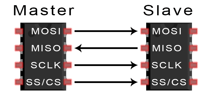
- MOSI (Master Output/Secondary Input): Line for the master to send data to the secondary.
- MISO (Master Input/Secondary Output): Line for the secondary to send data to the master.
- SCLK (Clock): Line for the clock signal.
- SS/CS (Secondary Select/Chip Select): Line for the master to select which secondary to send data to.
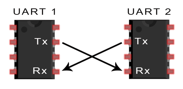
UART
Only two wires are needed to transmit data between two UARTs. Data flows from the Tx pin of the transmitting UART to the Rx pin of the receiving
UART.
UARTs transmit data asynchronously, which means there is no clock signal to synchronize the output of bits from the transmitting UART to the
sampling of bits by the receiving UART. Instead of a clock signal, the transmitting UART adds start and stop bits to the data packet being
transferred. These bits define the beginning and end of the data packet so the receiving UART knows when to start reading the bits.
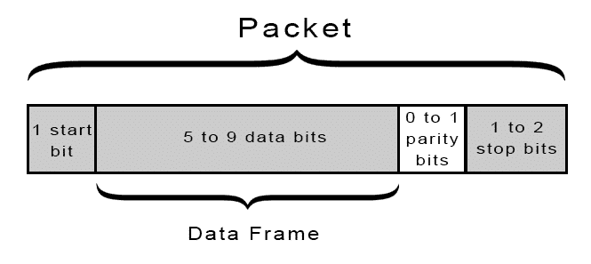
UART transmitted data is organized into packets. Each packet contains 1 start bit, 5 to 9 data bits (depending on the UART), an optional parity bit, and 1 or 2 stop bits:
Comparison table between I2C, SPI and UART
| Protocol | Characteristics | Advantages | Disadvantages |
|---|---|---|---|
| I2C |
|
|
|
| SPI |
|
|
|
| UART |
|
|
|
Communication Protocol
We used UART, a basic and reliable protocol that only requires a TX pin, RX pin, and a shared ground (GND). Both boards communicated at 9600 baud. Commands were sent as single ASCII characters:
- L → Move servos left (180°)
- R → Move servos right (0°)
- S → Move servos to center (90°)
Xiao RP2040 – Sender
What it does:
We used the Xiao RP2040 to read the state of three buttons. Depending on which button is pressed, it sends a single character via Serial.write() through its TX pin.
Wiring:
| Button | RP2040 Pin |
|---|---|
| Right | D10 |
| Left | D9 |
| Center | D8 |
Code
Xiao ESP32S3 – Receiver + Servo Control
What it does:
We used the Xiao ESP32S3 to receive UART commands using Serial1 on GPIO44 (RX). The board listens for characters and moves three servos connected to D2, D3, and D4. We also enabled USB Serial to print the received command for debugging.| Button | RP2040 Pin |
|---|---|
| Right | D10 |
| Left | D9 |
| Center | D8 |
Why we built it this way:
We decided to split the system into input (RP2040) and output (ESP32S3) boards to keep the logic modular and clean. Sending simple one-letter commands makes the communication efficient and easy to debug. We chose GPIO44 for RX because it's compatible with Serial1, and we kept USB serial free for monitoring. The ESP32Servo library lets us control servos with precise PWM using a range from 500 to 2500 µs, ensuring good accuracy and smooth motion.
Code
Result
We successfully achieved UART communication between the two boards. Button presses on the RP2040 were correctly interpreted by the ESP32S3, and all three servos responded instantly. The system was stable and easy to debug thanks to the USB serial output showing received commands in real time.