2025
Stanley Amaechi

This site is my personal portfolio developed during Fab Academy 2025.
© 2025 Stanley Amaechi | Template by Bootstrapious

This work is licensed under a Creative Commons Attribution-NonCommercial-ShareAlike 4.0 International License.
Week 3. Computer controlled cutting
This week, is composed of Group assignment and Individual assignments. The group assignment composes of safety training, characterization of the lasercutter's focus, power, speed, rate, kerf, joint clearance, types and group documentation. For the Individual assignment we continue with design, lasercut, document a parametric construction kit, accounting for the lasercutter and cutting on vinyl cutter
Tasks
-
Design, lasercut, and document a parametric construction kit:
- Create a parametric 2D design that accounts for the laser cutter's kerf
- Laser cut the design using the EPILOG LASER FUSION cutter
- Assemble the kit in multiple configurations and document the process
-
Cut something on the vinyl cutter:
- Design a simple graphic or text using vector-based software
- Use the vinyl cutter to create a sticker or decal
- Document the process and results
Process explanation
Group Assignment: Computer-Controlled Cutting
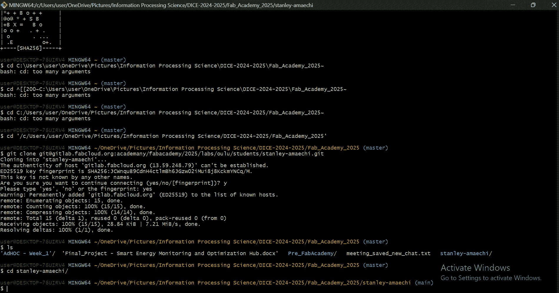
As part of the group assignment, I collaborated with Lauri Hallman and Shahmeer Adnan Rana to explore laser cutting techniques. Full details of our group work can be found below:
Key Learnings
-
Lab Safety: Covered fire hazards, PPE, ventilation, and machine maintenance.
-
Laser Cutter Setup: Powered on the EPILOG LASER FUSION, set focus, and prepared vector files in Inkscape.
-
Parameter Testing: Experimented with different settings to achieve optimal cut quality on MDF.
-
Kerf & Joints: Measured 0.14mm kerf, adjusted designs, and tested different materials for fit.
This assignment provided hands-on experience in optimizing laser cutting parameters for precise fabrication.
Individual Assignment: Computer-Controlled Cutting
The group assignment acted as a platform to introduce us to the fundamentals of lasercutting, kerf, joints and Fusion 360 parametric designs. We ended up with an icing ontop, which was the vinyl cutter. See below the steps:
Parametric Construction Kit
Step 1: Understanding Parametric Design
Before starting, I researched parametric design principles. Parametric design involves creating models where dimensions are defined by parameters (e.g., kerf, material thickness) that can be adjusted easily. This ensures the design adapts to different materials or laser cutter settings.
Step 2: Choosing Software
I decided to use Fusion 360 for parametric modeling because it allows me to define dimensions as variables and update them dynamically. These designs, which are parameterized (including calculated kerf), would then be transferred to Inkscape and printed on the laser cutter.
Step 3: Defining Parameters
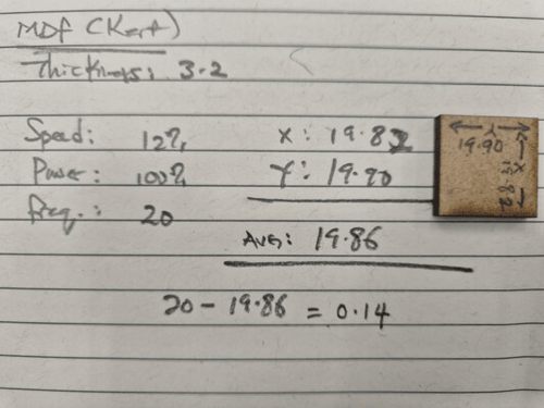
I carried out a personal evaluation of the kerf test on MDF, after the group exercise, to reinforce the knowledge. A bit of YouTube videos also gave me clarity. The kerf was calculated as follows:
- Kerf: 0.14mm (for MDF)
- Material Thickness: 3.2mm (MDF)
- Laser Speed: 12%
- Power: 100%
- Frequency: 20
The kerf of 0.14mm was used as a parameterized variable in Fusion 360 so I could adjust it later if needed. The kerf was calculated using the formula:
Step 4: Designing the Kit
I designed a simple press-fit construction kit with interlocking pieces. The kit included:
- Base Pieces: Rectangular tiles with slots.
- Connectors: Smaller pieces with tabs to fit into the slots.
- Variations: Some pieces had curved edges for creative assembly (tested my hand on chamfers).
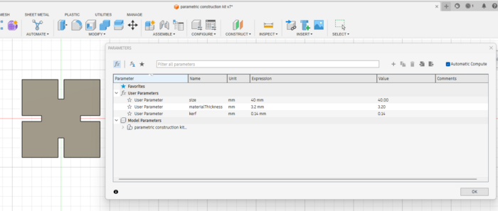
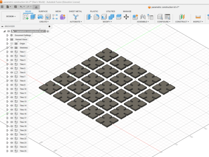
The base piece was designed in fusion 360, with the dimensions parametric
The rectangular pattern from the solid create drop down menu was used in replicating the base piece
Step 5: Accounting for Kerf
To compensate for the laser cutter’s kerf, I offset the cutting paths by half the kerf value (0.07mm) in the design software (kerf/2). This ensured the slots and tabs would fit snugly as calculated in Figure 2.
Step 6: Preparing the File for Laser Cutting
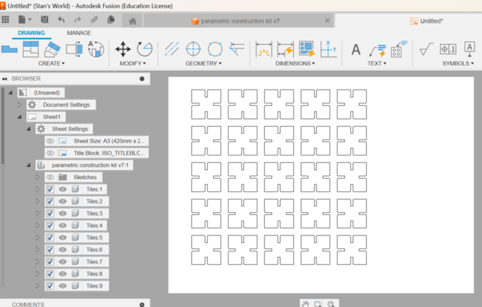
I exported the design as a .pdf file and imported it into Inkscape to further confirm the lines were correct before cutting.
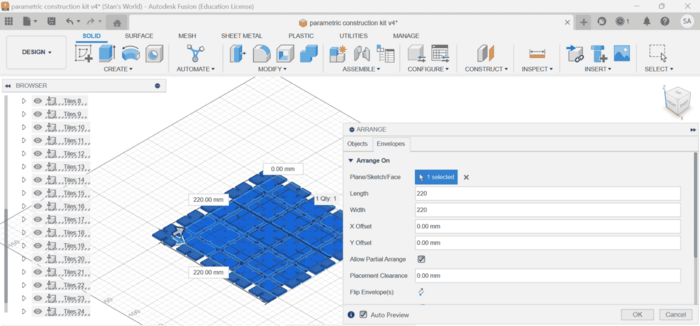
The below pictures visualizes, how the base image is been converted into a component first, converted to a 2 D layout and then it's set for export. I choose .pdf as a personal preference.
Step 7: Setting Up the Laser Cutter
Using the EPILOG LASER FUSION cutter, I followed these steps:
-
Power On:Turned on the machine and ensured the emergency stop button was disengaged
-
Focus Adjustment:Used the triangular gauge to set the focus correctly
-
Material Placement:Secured the MDF sheet on the cutting bed
-
Origin Setting:Used the Jog function to set the origin point
-
Settings:Applied optimal settings from group assignment:
- Speed: 12%
- Power: 100%
- Frequency: 20
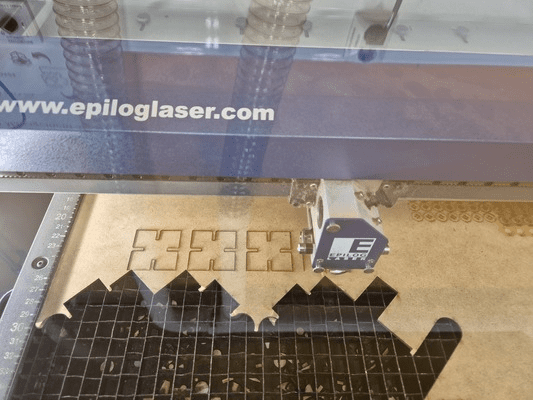
Step 8: Executing the Cut
I sent the file to the laser cutter and monitored the process to ensure clean cuts. The machine cut through the MDF smoothly, with little burn marks on the edges (I seem to have mastered the art of setting the focus and other parameters).
The below pictures visualizes, how the base image is been converted into a component first, converted to a 2 D layout and then it's set for export. I choose .pdf as a personal preference.
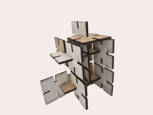
Step 9: Assembling the Kit
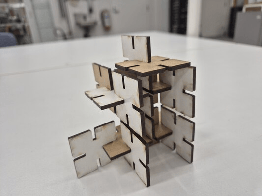
After cutting, I removed the pieces from the bed and assembled them in different configurations. The joints fit snugly, and the kit was versatile enough to create various structures, which gives us our lovely parametric assembled image below.
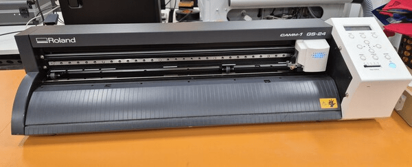
Vinyl Cutter Process
The vinyl cutter used in carrying out the vinyl section of this week assignment was the Roland GS-24 in the lab. It works like every typical vinyl cutter by cutting through the vinyl layer while leaving the backing intact, allowing for easy transfer. We have to first have a design before we cut.
1. Preparing Your Design in Inkscape
Step 1: Create The Design
The below pictures in combination with listed notes and descriptions, would tell a story of the design in inkscape to the actual printing using the Roland Vinyl cutter:
- Use vector graphics (avoid raster images) for smooth cutting (inkscape allows to trace and generate vectorised objects from raster images).
- Use only black stroke, no fill for cut lines.
Step 2: Set Stroke and Path Properties
- Stroke width:
0.01 mm(hairline) - Path should be continuous and closed.
- Use Boolean operations (
Path > Union,Path > Difference) to simplify overlapping shapes.
Step 3: Save as SVG or PDF
The Roland cutter software may not support all Inkscape formats.
- Preferred:
SVG(for compatibility with CutStudio) - Alternative:
PDF(The PDF format, always saves the day. Note save as PDF, not print to PDF, to save dimensions in the PDF file.)

2. Setting Up the Roland GS-24
Step 1: Loading the Vinyl
The steps taken in using the roland cutter would be listed below, so it can be easily replicated and hopefully the same result achieved:
- Turn on the Roland GS-24.
- Raise the lever on the back to open the pinch rollers.
- Insert the vinyl sheet or roll, aligning it with the marked guides.
- Adjust the pinch rollers to match the vinyl width.
- Lower the lever to secure the vinyl in place.
Step 2: Setting Material Size
- Select
ROLLorSHEETmode on the cutter. - The GS-24 will automatically detect the width.
- Use the arrow keys to fine-tune positioning.
- Press
ENTERto confirm.
3. Cutting Your Design
Step 1: Open Roland CutStudio
- Launch CutStudio on your computer.
- Import your
SVG/PDFfile. - Select the entire design and set the stroke width to hairline.
Step 2: Adjust Cutting Settings
- Blade Force:
90-120 gf(adjust depending on vinyl thickness) - Cutting Speed:
10-20 cm/s(fine details) or30-50 cm/s(larger designs) - Offset:
0.25 mm(for standard Roland blades)
Step 3: Send to Cutter
- Click
Cutin CutStudio. - Select the Roland GS-24 as the printer.
- Click
OKto begin cutting.
4. Weeding & Transferring
Step 1: Weeding
- Used a weeding tool or tweezers to remove unwanted vinyl.
Step 2: Applying Transfer Tape
- Cut a piece of transfer tape slightly larger than your design.
- Peeled the backing of the transfer tape and appllied it smoothly over the vinyl.
5. Applying the Vinyl to my Phone
I peeled off the vinyl backing, leaving the design on the transfer tape. I positioned the design carefully on the back of my phone, applied some pressure and slowly peeled off the tape.
Resources utilized
- Software:: Fusion 360, Inkscape.
- Hardware: EPILOG LASER FUSION cutter, vinyl cutter.
- Materials:: 3.2mm MDF, vinyl sheet, transfer tape.
- Tools:: Calipers, weeding tool (tweezers).
Reflection
Summary
This assignment taught me how to create parametric designs and use computer-controlled cutting tools effectively. I successfully designed and laser-cut a parametric construction kit and created a vinyl sticker. Conversion of word written documentation was converted to HTML, using ChatGPT, in order to make documentation faster, but the content is solely written by me.
Main Difficulties
-
Parametric Design:Ensuring the design was truly parametric and adaptable to different kerf values
-
Vinyl Cutting:Transferring the design without tearing or misalignment (since my design was 2mm text thickness)
Main Learnings
-
Parametric Design:Using variables in Fusion 360 for flexible designs
-
Laser Cutting:Understanding power/speed/focus effects on cut quality
-
Vinyl Cutting:Mastering weeding and transfer techniques
Model Files
-
Vinyl Cutter Design: FabLab 2025 Design
-
Fusion 360 Design: Parametric press fit kit