


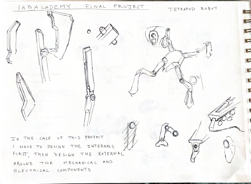
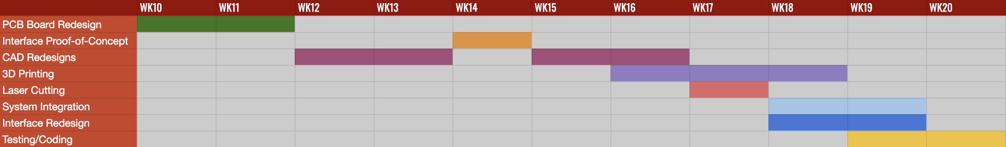
My immediate thoughts when told that I could create whatever I wanted for the final project was a tetrapod "spider" robot with a disco head for fun. I am not too sure I want to move forward with a disco-ball head but I do know I would like to build a four-legged robot reminiscent of insects and spiders. My love of sci-fi pushed me in this direction. At first I wanted to focus on aesthetics, but as I thought about it further and further I realized I would have to focus on parts, pieces, and mechanical components first before I attempted to design the exterior. Keeping this in mind, I shifted my focus towards planning different stages of the project using my understanding of spiral development. The intended audience for this project is myself. I've always wanted to build and design a robot so we'll see how that turns out over the next few months.
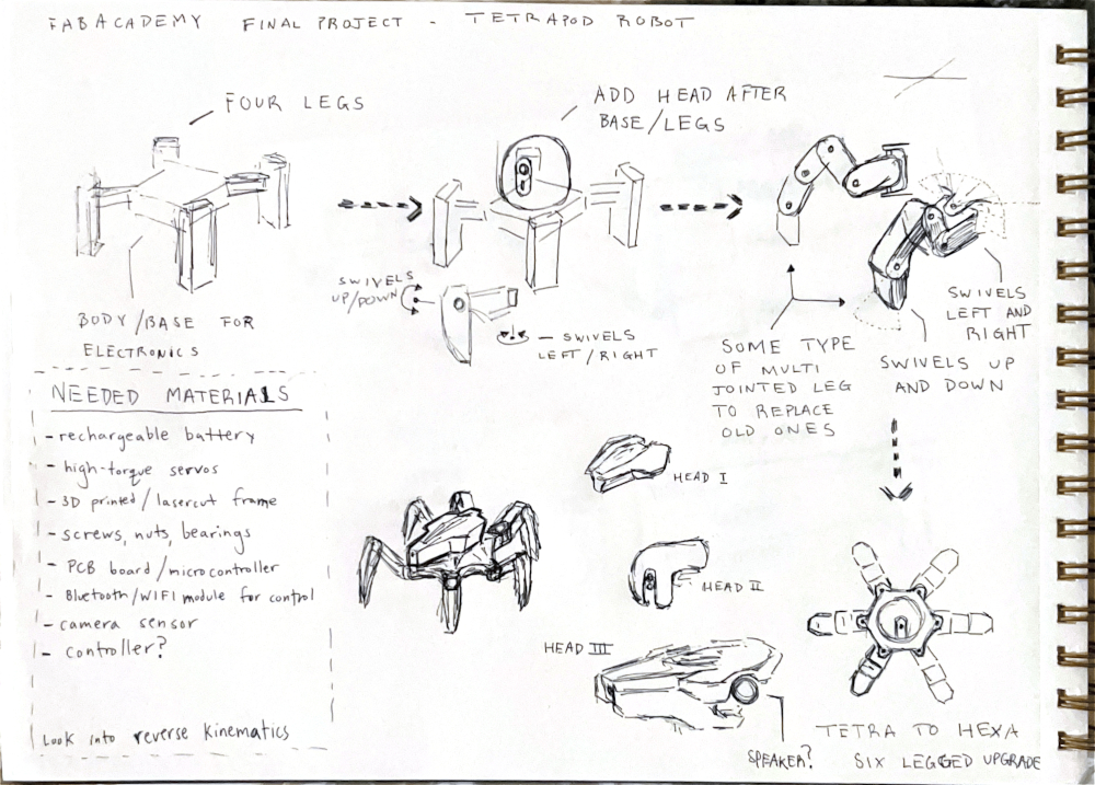
The first stage starts off simple, a central base or core with 4 legs, each housing two servos. The second stage, involves incorporating a head with a camera sensor. The third proposes upgrading the legs from double-jointed legs to triple-jointed legs allowing for more nuanced and controlled movements. The fourth and final stage proposes turning the tetrapod into a hexapod. If extra time is leftover maybe I could create a disco-ball head variant to turn it into a true party bot.
While sci-fi is what pulls me in the direction of making a a tetrapod, my real world inspiration are a few makers on YouTube that make putting together a robot look easy. There will be a list of videos below -
To further understand what I was going to be modeling, I printed some of the publicly available files of iOlly 2DOF belonging to Erik Lely.
I put the iOlly 2DOF's leg together. Once I had it built it was becoming easier to understand how the leg would function mechanically and how it was put together. Using this 2DOF(two degrees of freedom) robot as basis, I planned on using the same structural and mechanical principles for my robot.
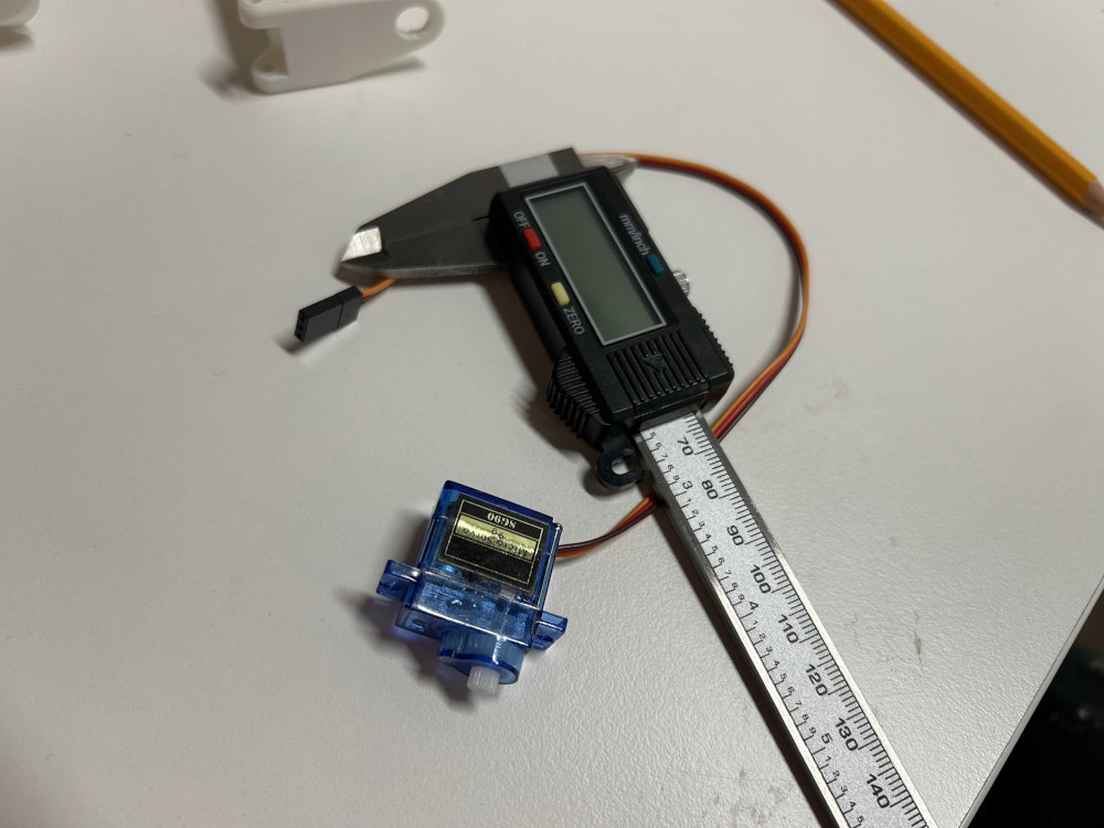
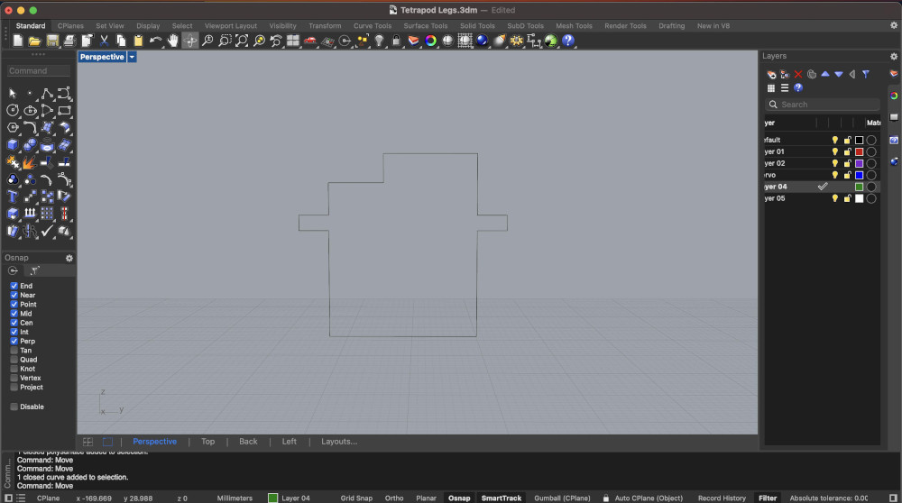
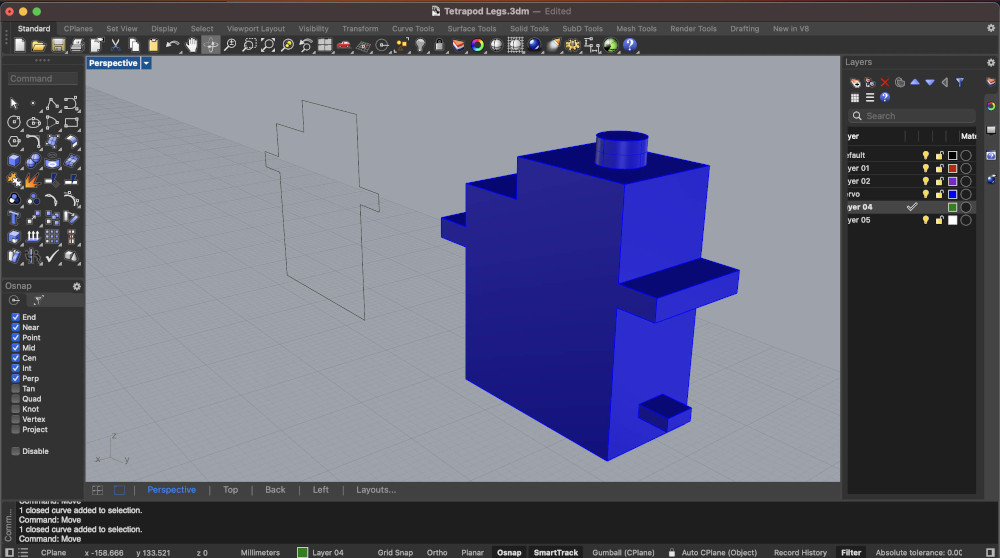
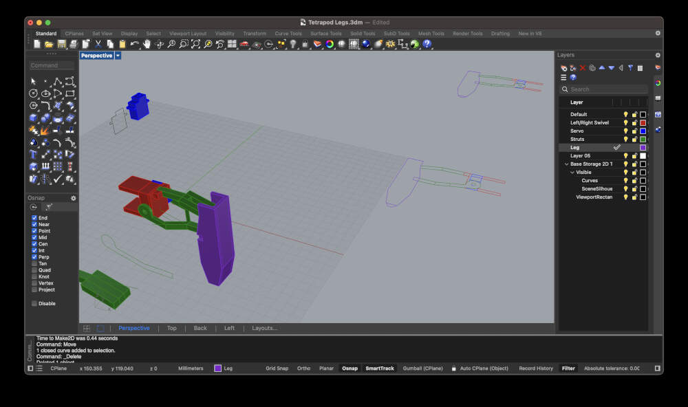
After studying how the leg functions, I got to work on modeling a similar structure for my robots legs with the future intent of changing the overall design and incorporating my own aesthetic preferences and tweaks. I started by using calipers to measure a microservo I had around. Using Rhino as my preferred 3D modeling software I used the Polyline command in Rhino to create the servos outline. I then used the ExtrudeCrv command to make and closed polysurface or shape and then extruded some additional forms to represent the gear and cables that protrude from the servo. I modeled a rough enclosure for the servo and started modeling how the connections would come together between the leg and the swivel using the struts.
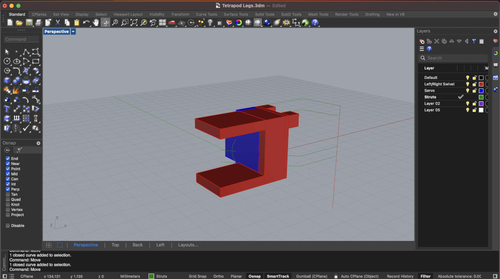
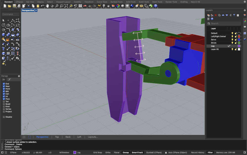
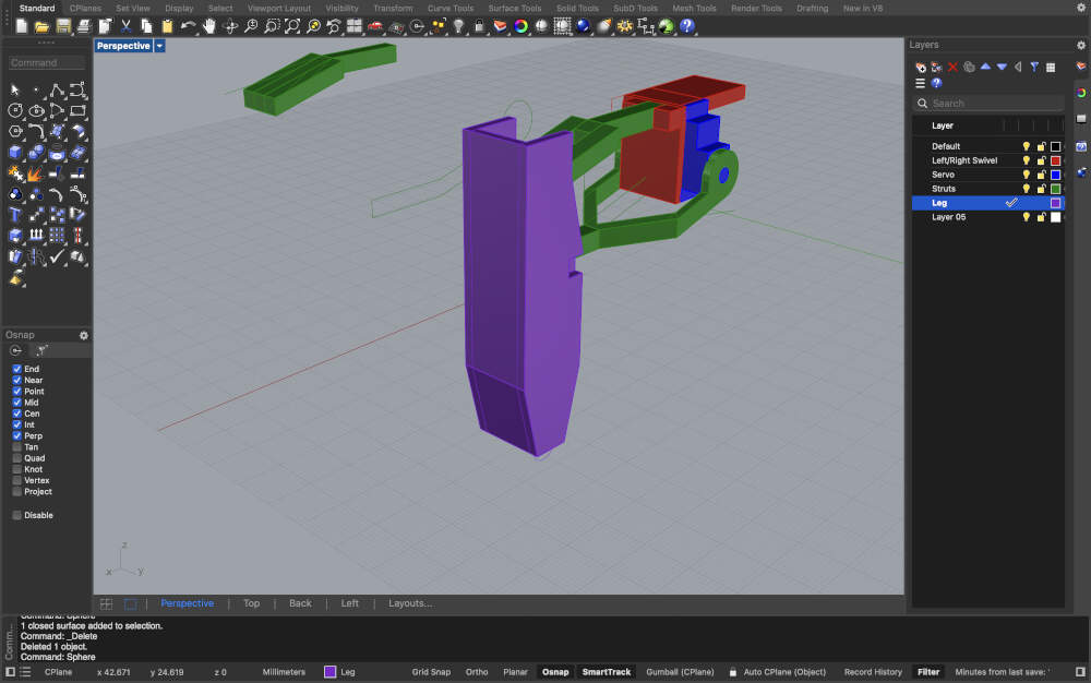
Extruding the struts was the next step for me. Both struts were forked so I extruded and duplicated the extrusions placing them on opposite ends where needed and later joined them together using basic polyline and surface extrusion commands supplemented by the trimming command. My computer failed to save the video for the last portion of the leg, but I drew up a rough outline that I extruded, mirrored, and connected via an extrusion and boolean union. Lastly, I added a sphere at the base of the leg as a way of representing where I want to add a rubber end cap to prevent any slips while walking.

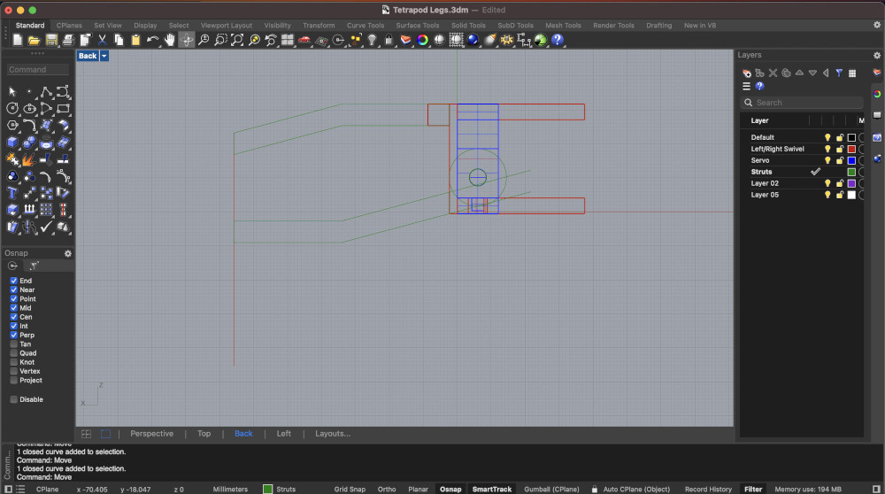
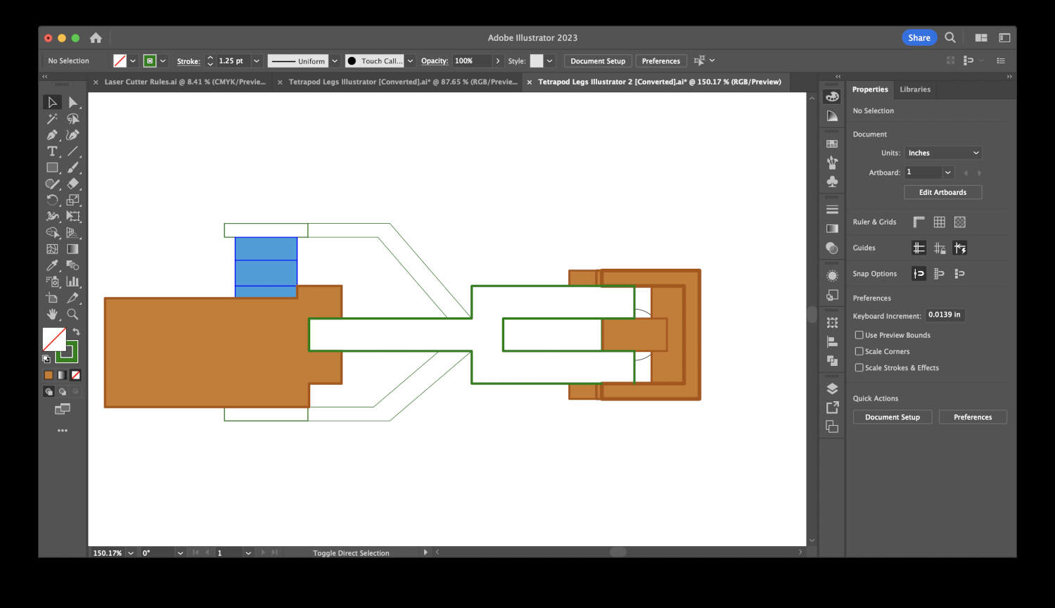
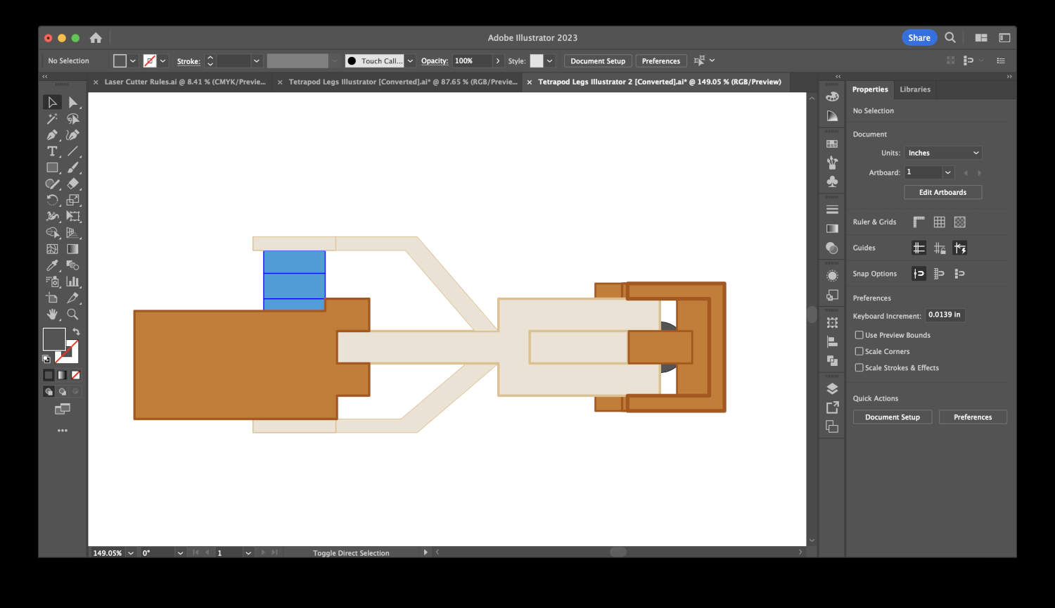
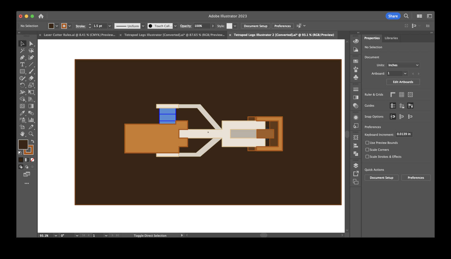
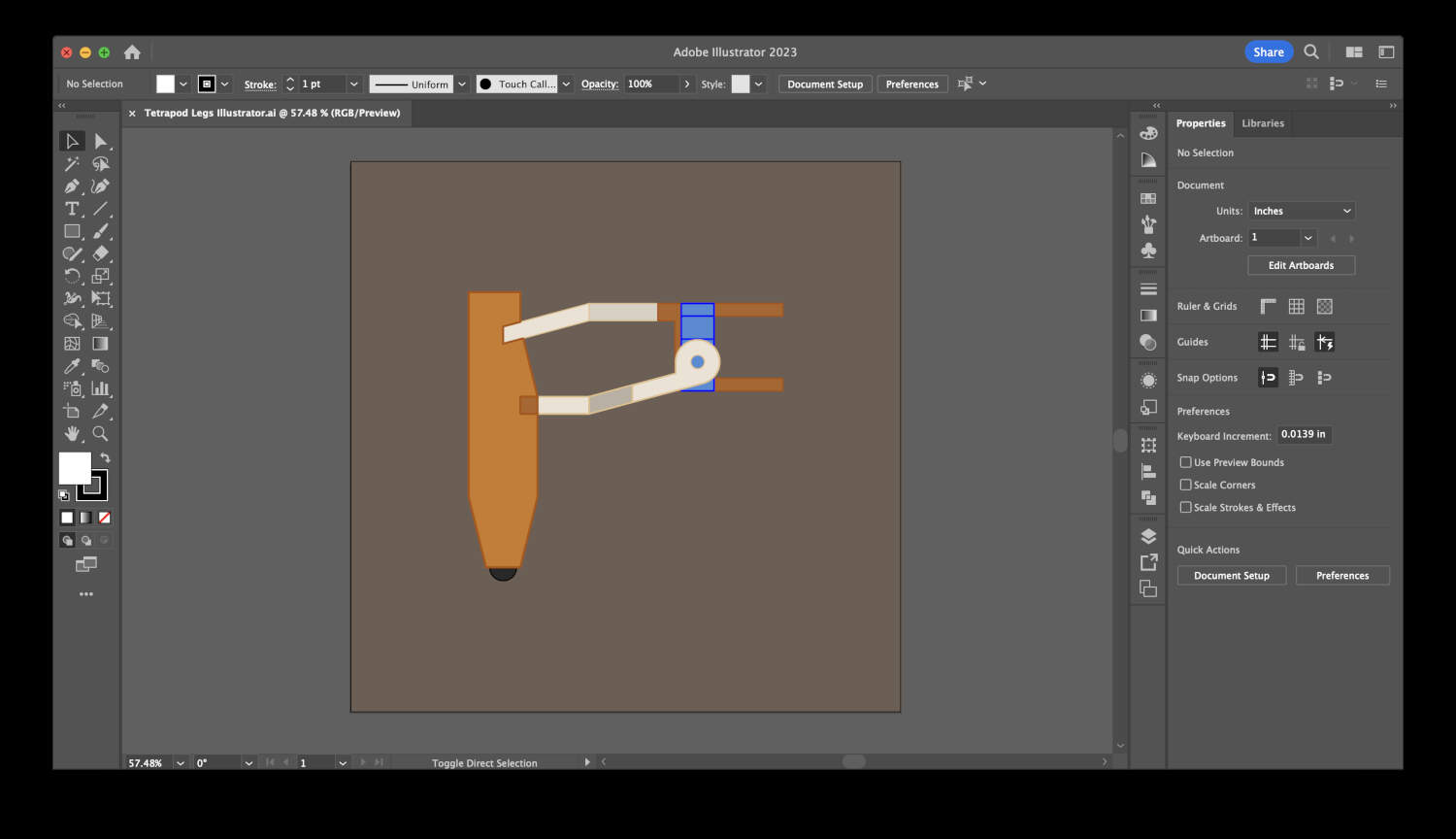
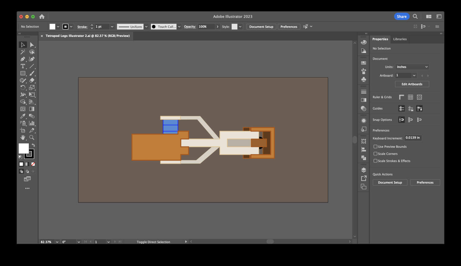
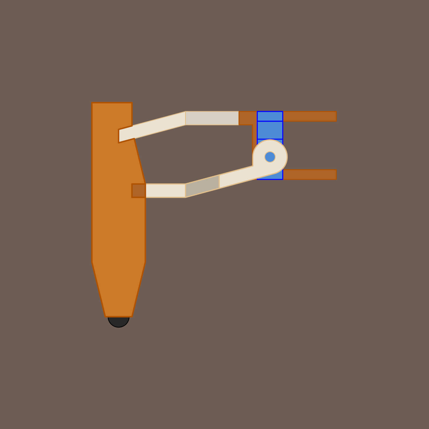
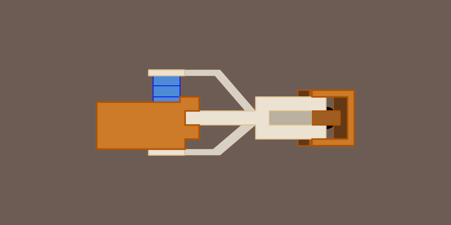
After finishing the rough model, I used the Make2D command in Rhino. This command allows me to turn my 3D model into a 2D drawing. I was then able to select my drawing and use the Export Selected option to export my drawing as an .AI file to import into Illustrator. I chose to export the right and top orthographics views of the tetrapod leg.
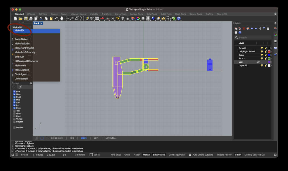
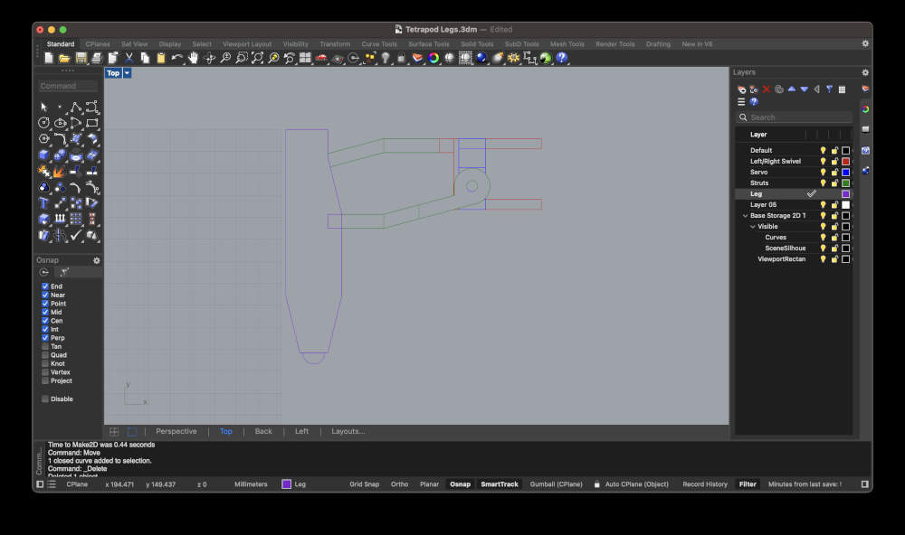

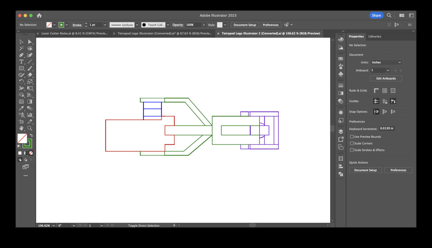
After finishing the rough model, I used the Make2D command in Rhino. This command allows me to turn my 3D model into a 2D drawing. I was then able to select my drawing and use the Export Selected option to export my drawing as an .AI file to import into Illustrator. I chose to export the right and top orthographics views of the tetrapod leg. Importing into illustrator was really simple. It imports exactly as it looked in Rhino with all the layer lines and colors you chose to use. I started editing the line color and line weights to create a simple illustration of the legs from the right and top views. Colors were chosen to differentiate between certain parts and pieces and line weights were used to highlight what was closest and furthest away. I've included the final drawings in the last two slides.
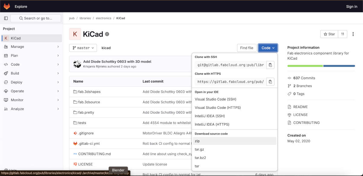
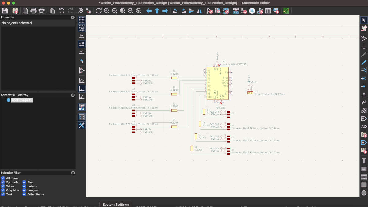
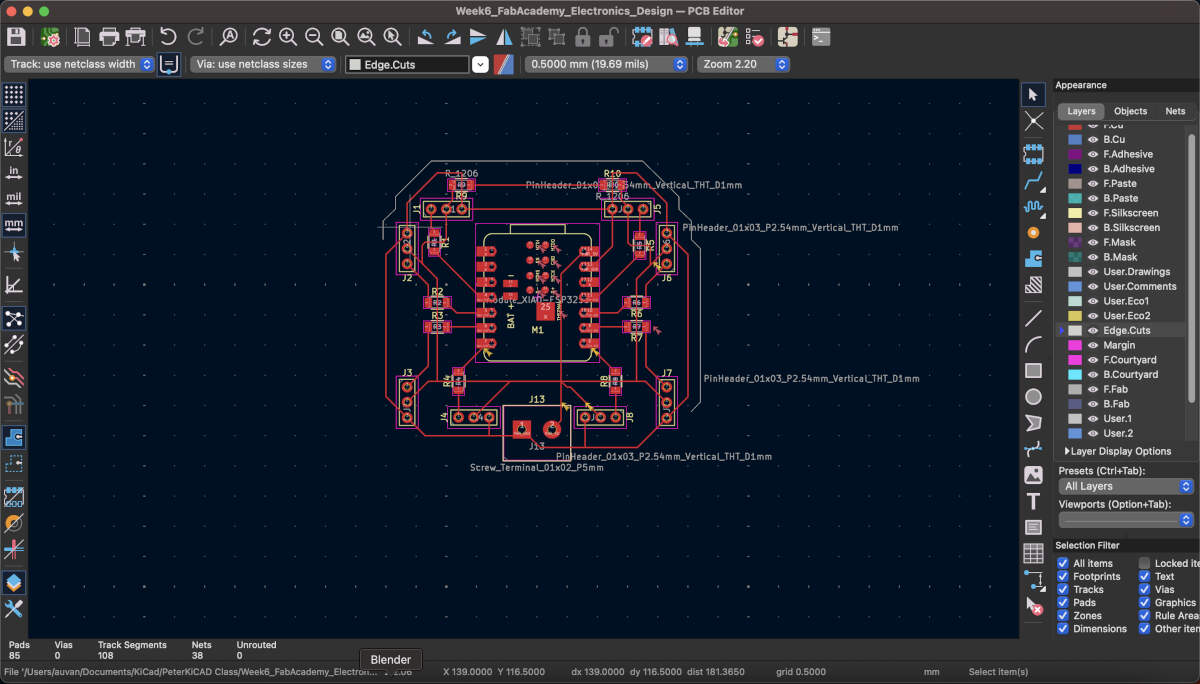
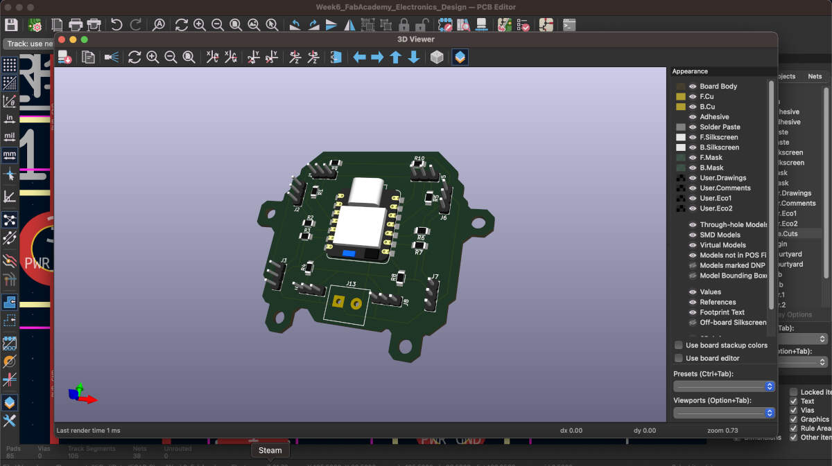
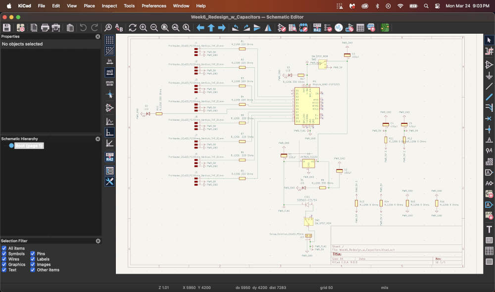
I chose KiCAD as the EDA tool to design my PCB. It is an open-source software that allows me to create circuit schematics and PCB's for milling, in addition to having a 3D visualizer built-in that lets me see the end result. I also used a FabAcademy library to supplement my design. This board is the first draft intended for use in my final project. It will incorporate eight 3-pin headers to go with the 8 servos needed for this project.
Slide 1: I installed the KiCAD FabAcademy footprint and symbol libraries to make use of in my design.
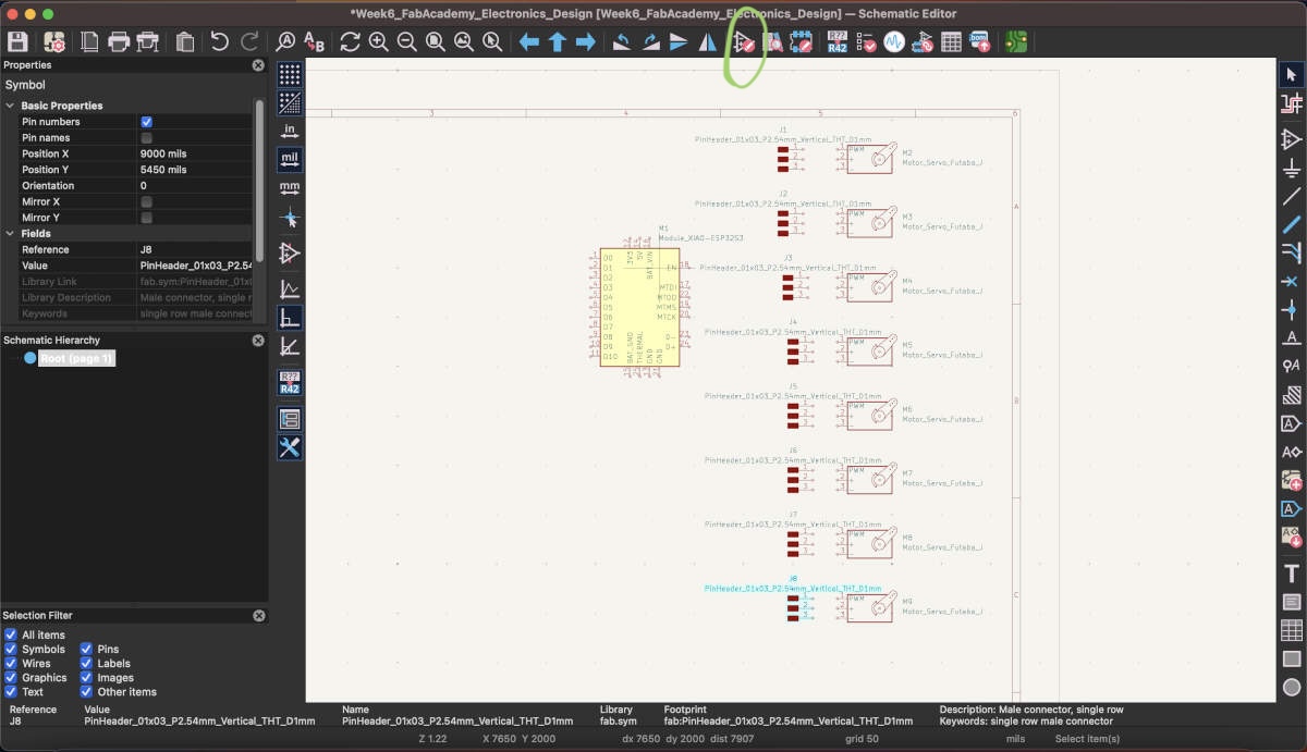
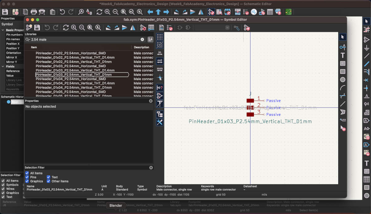
Slides 2-3: I had started adding in the components I believed were relevant to the project I had in mind using the Symbol Library. This allowed me to look up specific components that I would use within the circuit board.
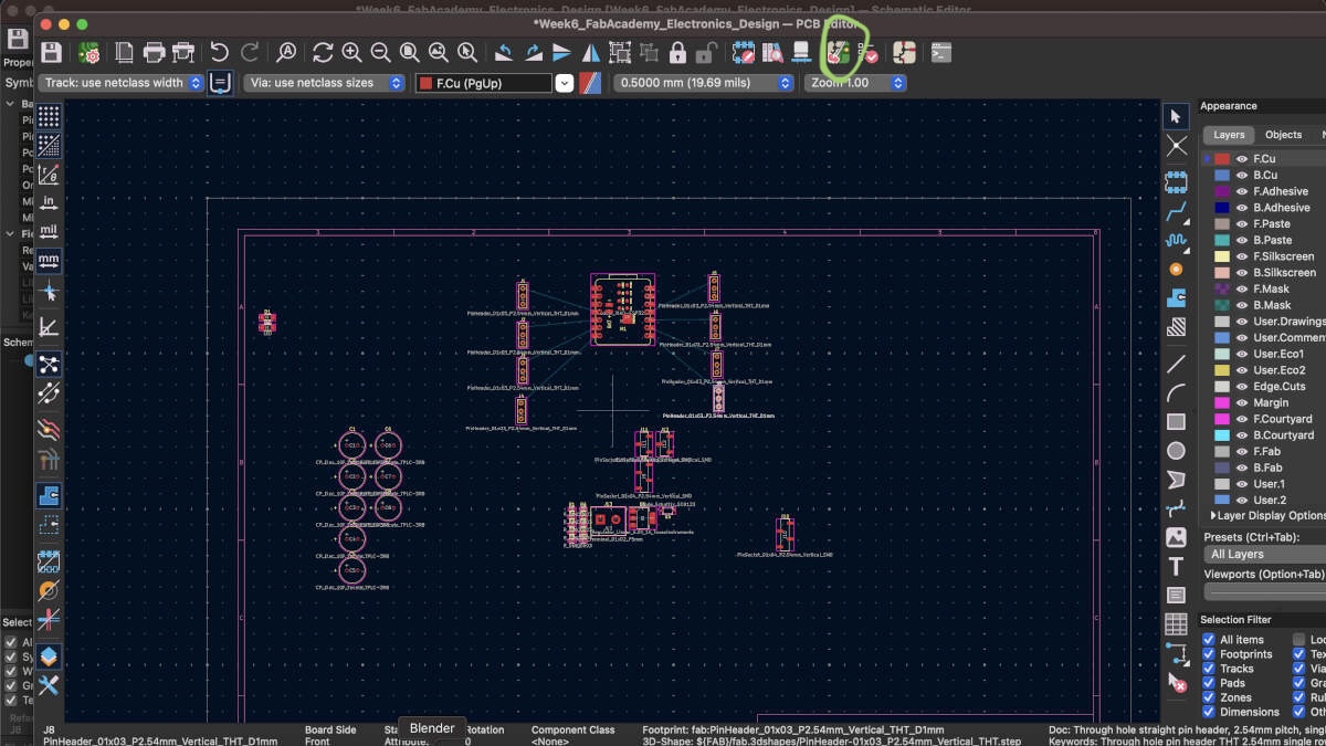
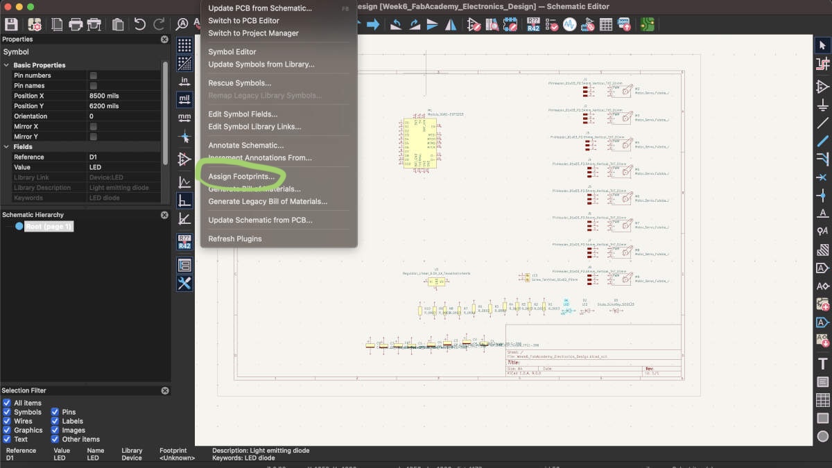
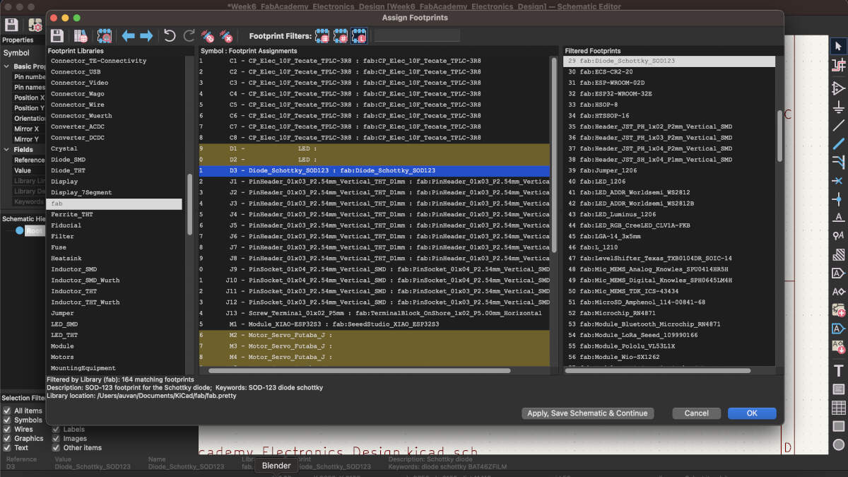
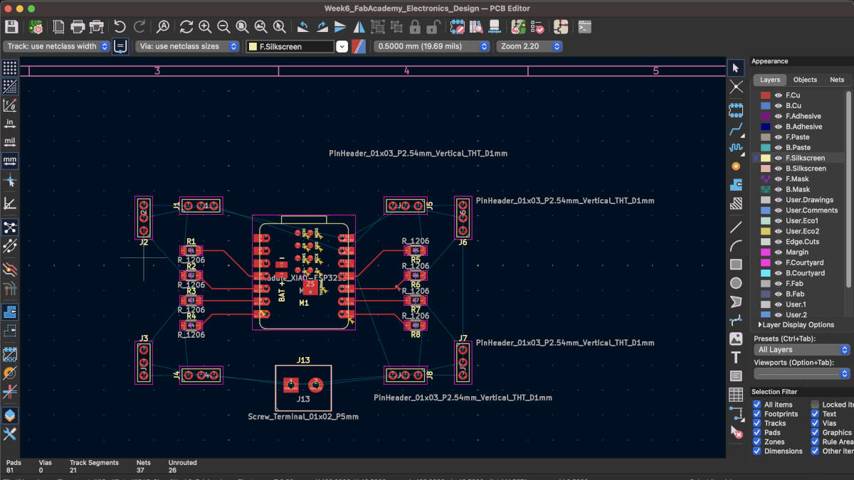
Slides 4-6: Once I was content with the components I was adding from the Symbol Library, I switched from the Schematic editor to the PCB editor. Here I was able to bring in the components I was linking together by pressing the button circled in green. This button allows me to update the PCB editor by bringing in all the components I had chosen in the Schematic editor. I slowly realized that not all components were there though. One of the errors I had consistently gotten when updating my PCB editor was something regarding footprints. Over time I realized that not all my components had an assigned footprint. Slide 5 demonstrates where I went to do this, and so I started assigning footprints to components I knew would be on the board. Servos remained unassigned due to them being external components.
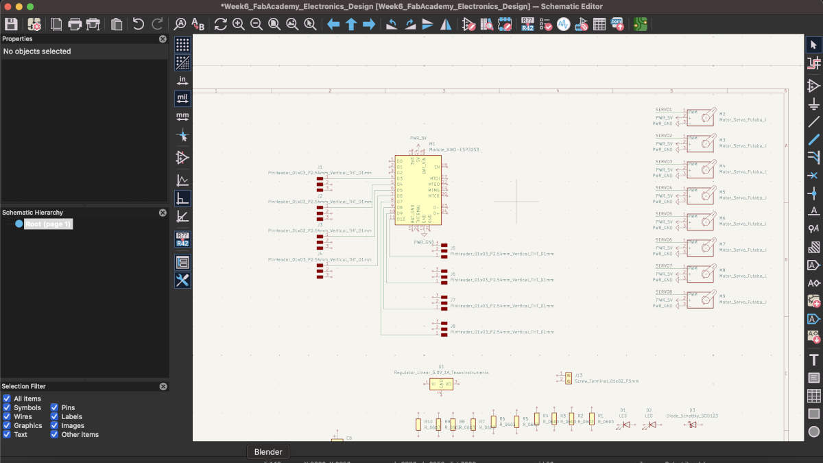
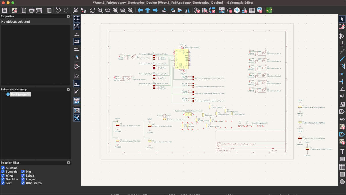
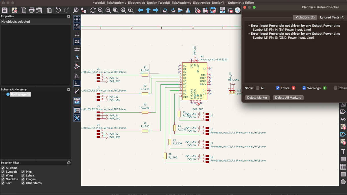
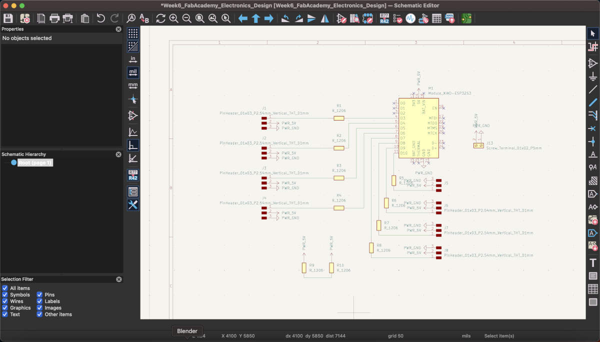
Slides 7-10: These next slides demonstrate the addition of new components and the beginning of making those components connect to one another. This is why the schematic editor is important as it allows to you organize your components and connections in a manner that is readable to the viewer rather than having the viewer analyze all the confusing snaking and winding paths on the PCB board itself. Slide 9 demonstrates errors I was receving when conducting an electrical check. Soon after I realized that this was occuring because I the 5V symbol doesn't function as an actual power pin, and to fix this I would have had to add an external power source like a battery. I excluded the battery source like I did the servos due to it being external even if relevant to the board. Slides 9-10 also demonstrate the vast simplification of my board. When speaking to an instructor I was told that many of the components I was trying to implement were not strictly necessary. They had specific uses that would be beneficial to the operation of the PCB but that I could do without them. I was really grateful to have been told this. Given my lack of familiarity with electronics I would not have been able to comfortably make a board while having so many components to take into consideration. This simplified everything for me as you can see in slide 10.
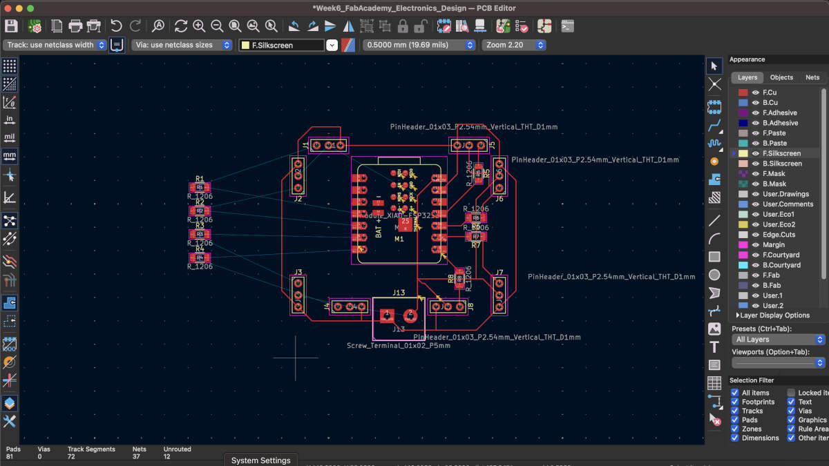
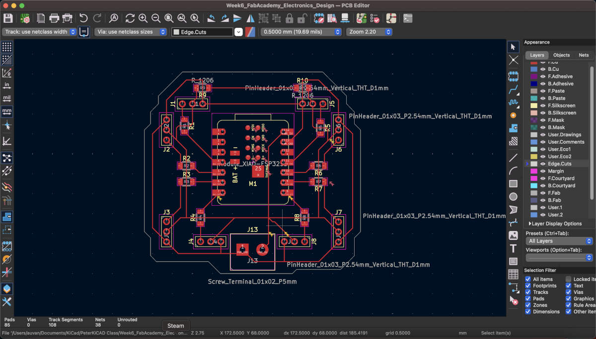
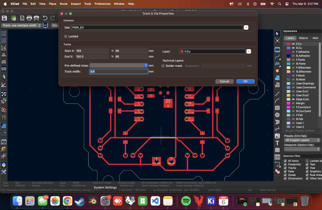
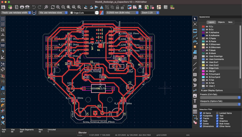
Slides 11-14: I went back to the PCB editor after streamlining the schematics. I started making connections based on the ones made in the Schematic editor. This is represented by the blue lines, which are not established connections yet. To properly establish them you have to make use of the red lines seen in the images so that the pins and other components on the board properly communicate with each other. These red lines will later but cut into the board to physically do the same. The connections began getting more convoluted so I added in two more 0 ohm resistors in Slide 13. The purpose of these were to close the PWR_5V loop going around the board by bridging over some of the PWR_GND lines. I was able to successfully do this and started drawing out the perimeter outline of my board. These white lines represented the PCB that was going to be cut out mimicking whatever shape is made with them.
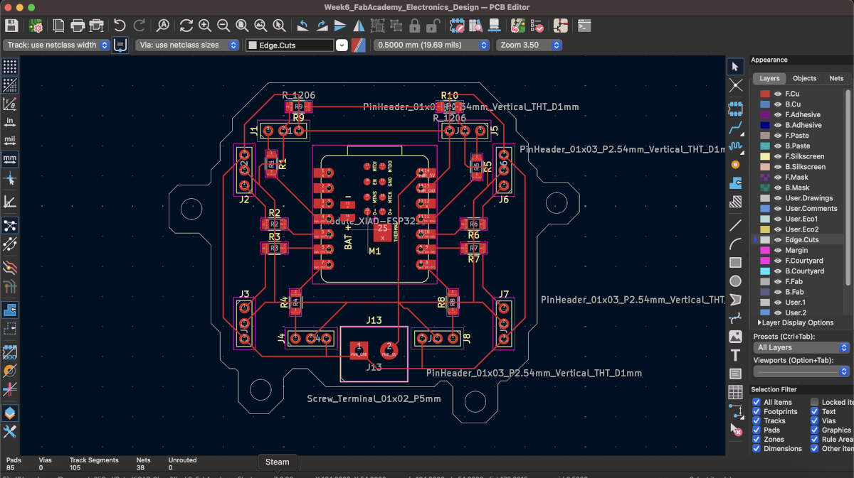
Slides 15-17: I finalized all connections and the outline but realized that in the future I would need to safely secure the board onto my final project so I created protusions with holes in them that would allow the board to sit on threaded heat set inserts and have screws secure it in place.
WK6 Electronics Design Documentation
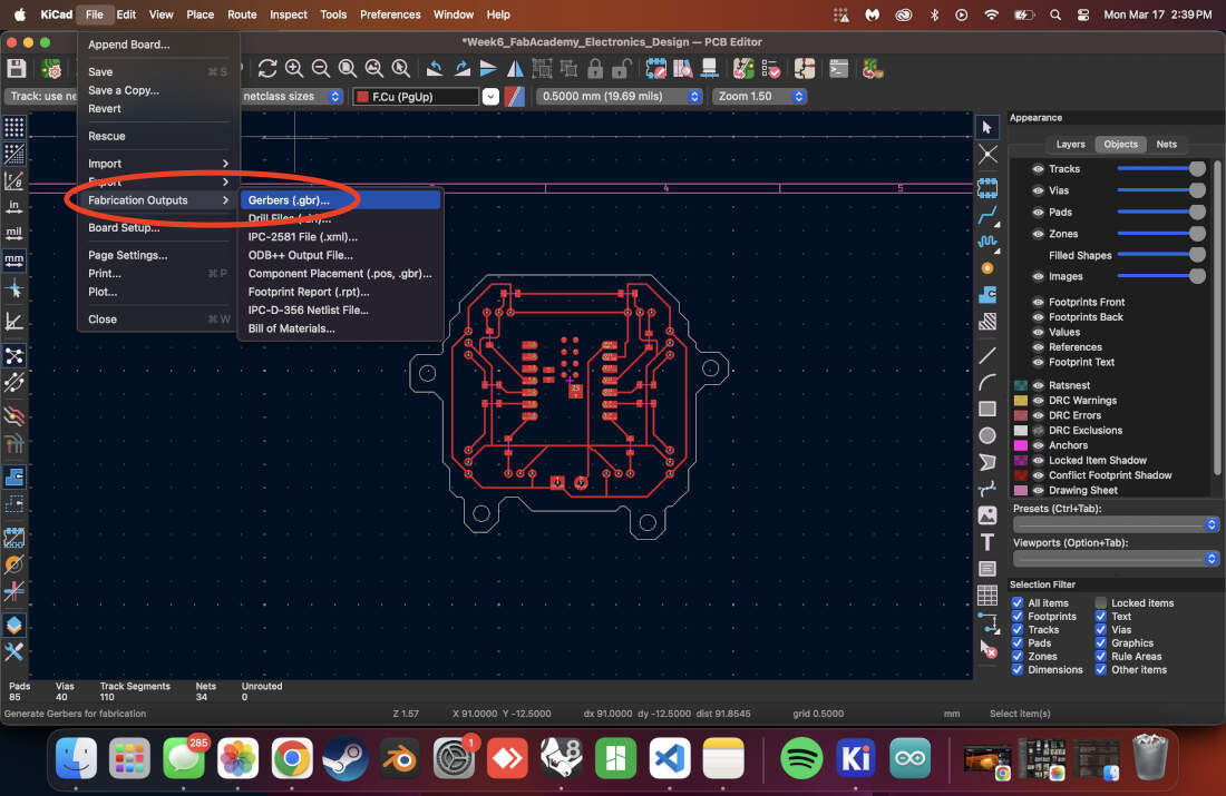
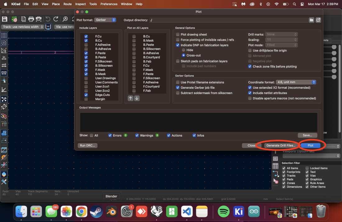
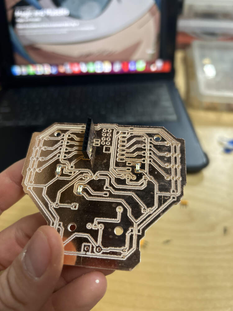
To begin producing my own PCB board I have to begin by exporting my Gerber and Drill files from KiCAD. To do so I have to go into KiCAD's fabrication outputs under the File tab, select the appropriate output directory for the gerber files, doing the same for the drill files and generating them, and then plotting the gerber files to complete the exports.
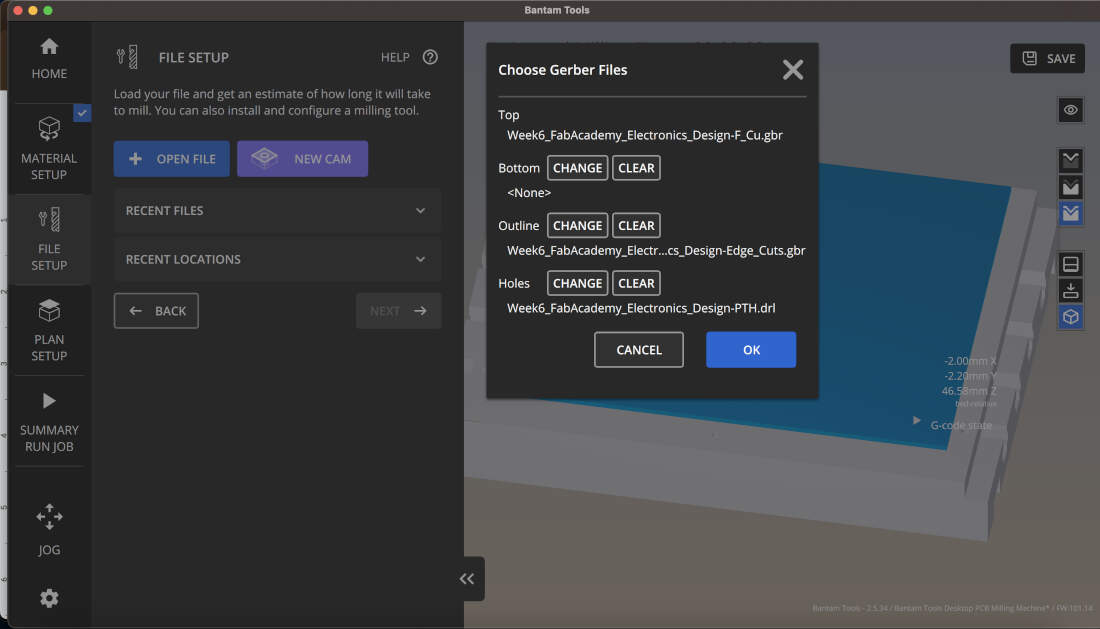
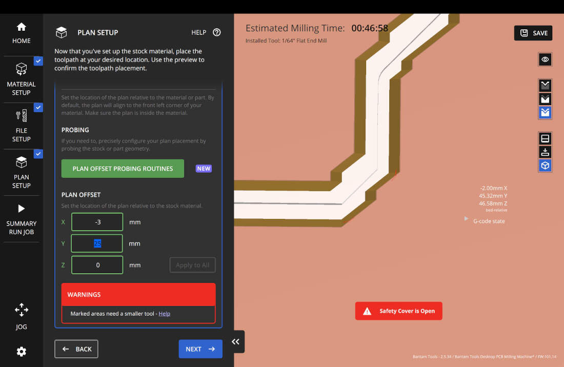
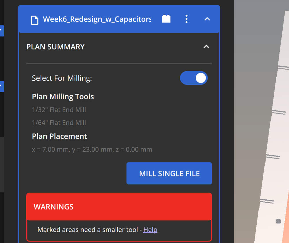
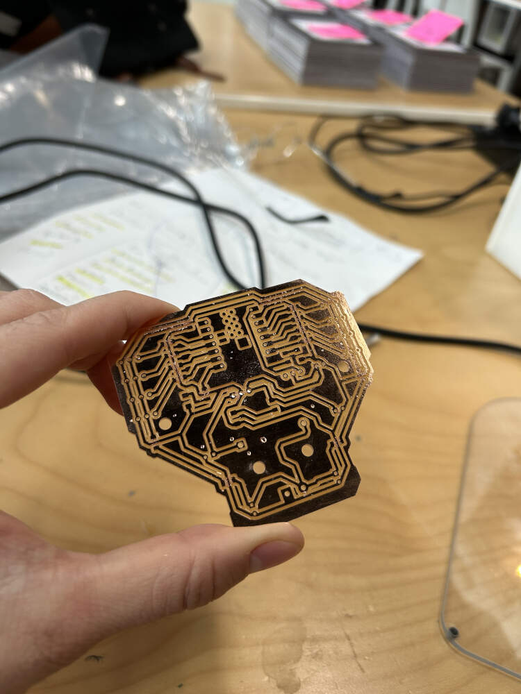
To mill my board, I downloaded the Bantam Tools Milling Machine Software because we have a discountinued version of the Bantam Tools PCB Milling Machine. In the software, we are prompted to install the tool of our choice. In my case I chose a 1/64 flat end mill. Additionally I measured the FR-1 copper clad boards with a caliper. I inputted the measurements into the program so that the materials dimensions would be simulated.
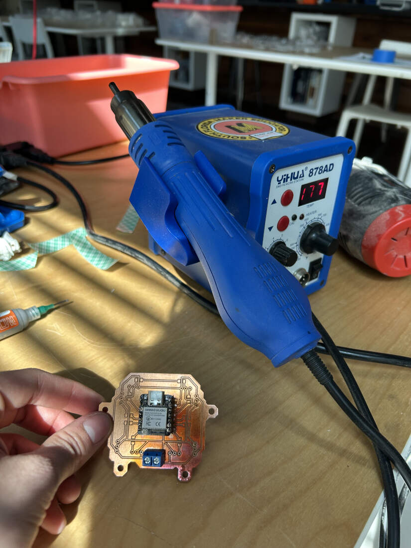
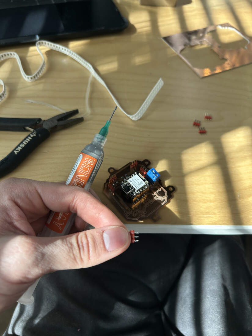
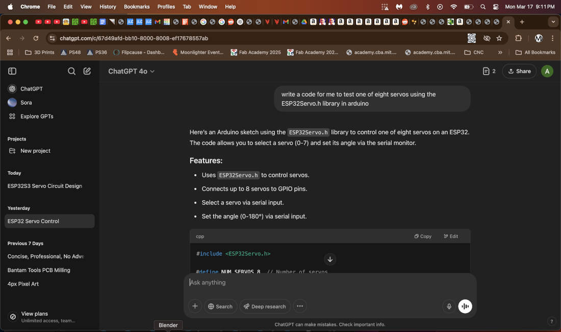
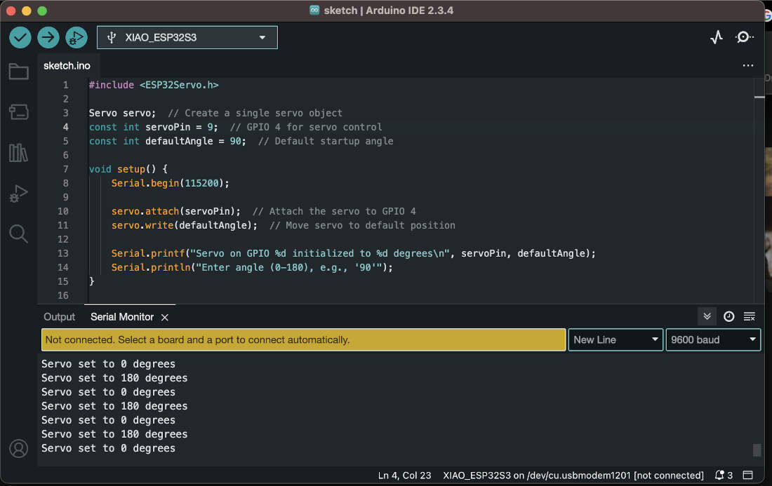
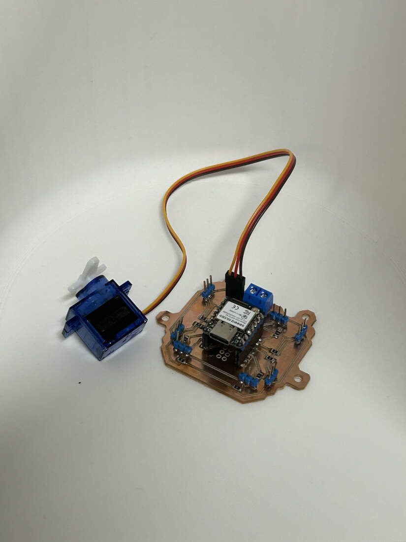
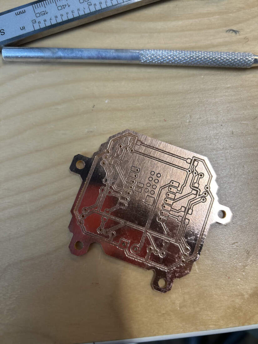
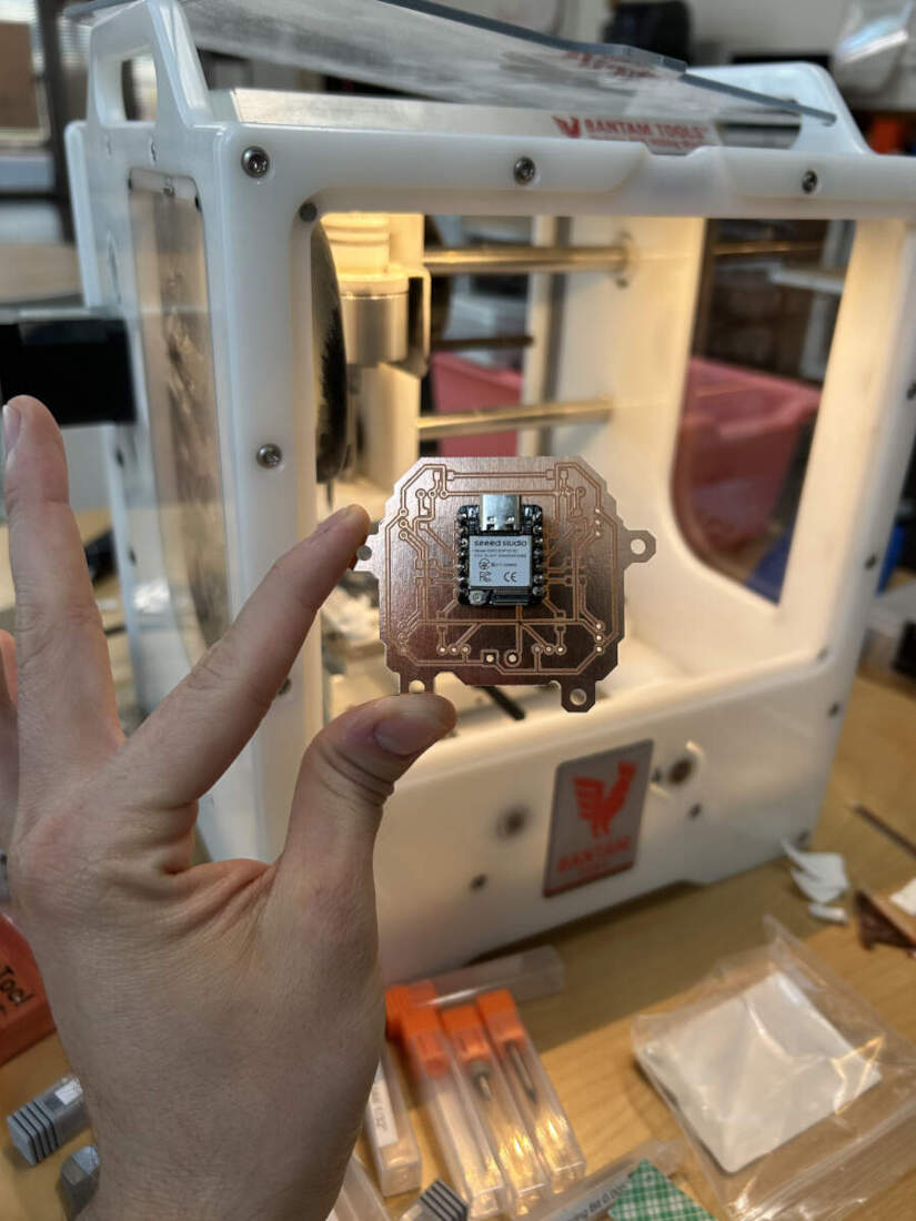
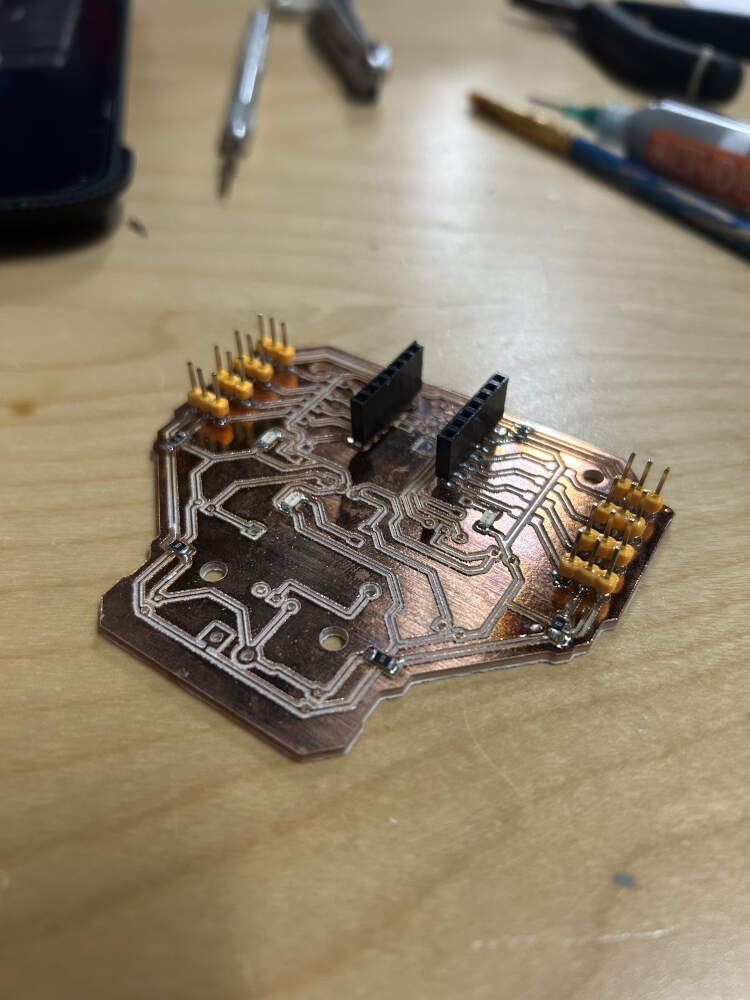
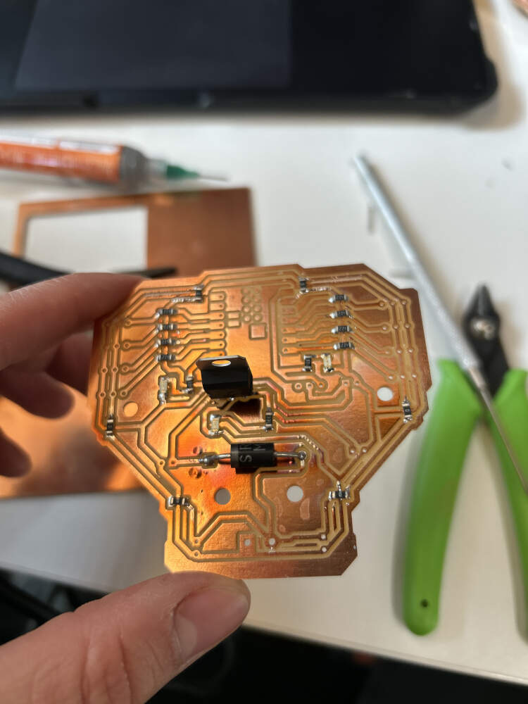
I started soldering my components onto the board by using a hot air gun and soldering paste. I would lay the paste either into the board or onto the pins on the components and then I would blast the soldering paste with 450 degrees of hot air. I was able to complete my first board this way. I inevitably fried the ESP32S3 on this board though. I think I crossed the multimeter rods I was using some wrong way and my board ended flashing red all the time. I went with my weird hunch and decided to proceed with milling and soldering another board and ESP32S3. This one worked perfectly. I asked ChatGPT to create some basic servo testing code for me and I pasted it into the Arduino IDE. This code served its purpose as it allowed me to test every single one of the relevant GPIO's attached to a servo by using the router terminal in the IDE to command the servos to change their angle. Eight of eight servos worked perfectly which made me really happy as this was my first time every making a functional PCB. All I had to do was change the GPIO pin I was interacting with to test each slot.
WK8 Electronics Production Documentation
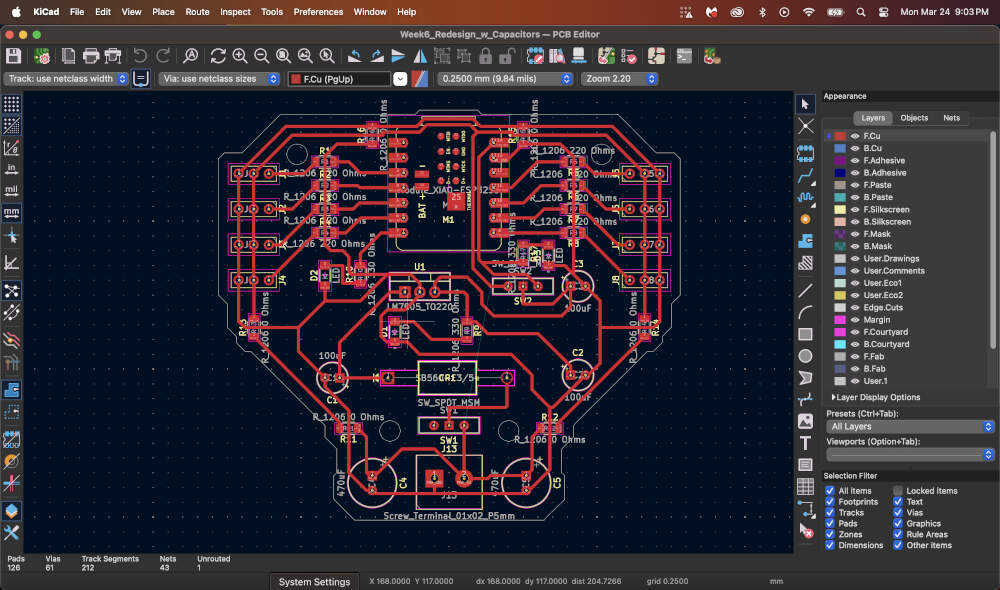
My original board did not have any protection so over the past week I had been redesigning my original board so that I could comfortably use up to 8 servos without having to worry about noise interference, component damage from excessive current, or voltage spikes. I have slowly been building up an understanding of electronic components but I still did not have the confidence to say that something I put together would be sufficient for a project I had in mind so I did some research and looked at other peoples projects and I came across this link -
4-Legged Spider Robot With 3D Printed Parts (8 Servo Motors and an ESP32) by MertArduino
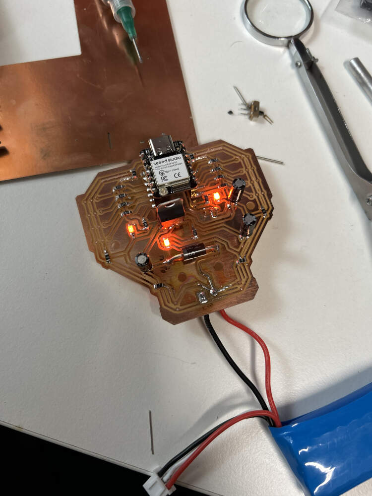
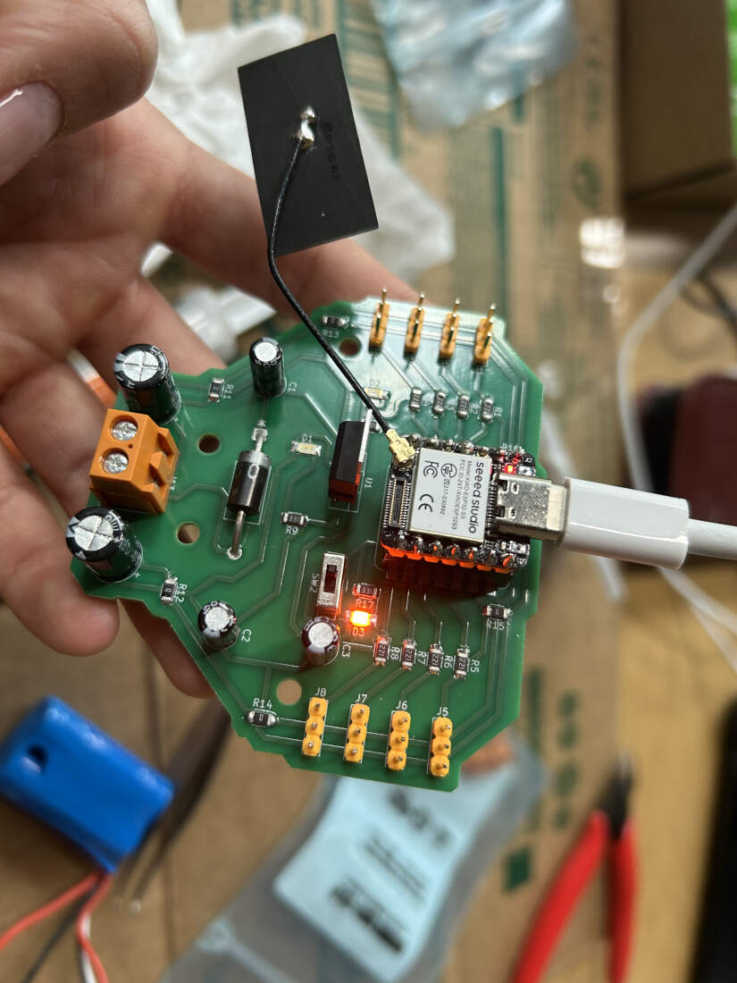
The Instructables tutorial features a four legged spider robot like the one I want to build for myself, but more importantly, they designed their own board. Using their board as a basis I then took many of the components they used and added them to mine such as the resistors (to prevent the LEDs from getting burnt out with excess current and the servos from receiving noise interference), 100uf and 470uf capacitors (to act as a buffer in the case of current peaks and voltage drops and as a filter to prevent electrical noise from reaching the servos), a 5V regulator(this converts the 7.4V external battery source into 5V as it reaches the microcontroller to prevent it from getting overloaded and burnt out), the SB560 diode (has electricity flow one way to the microcontroller), and the LED's (show electricity passing in certain areas, I added a third to experiment with potential statuses of my board).
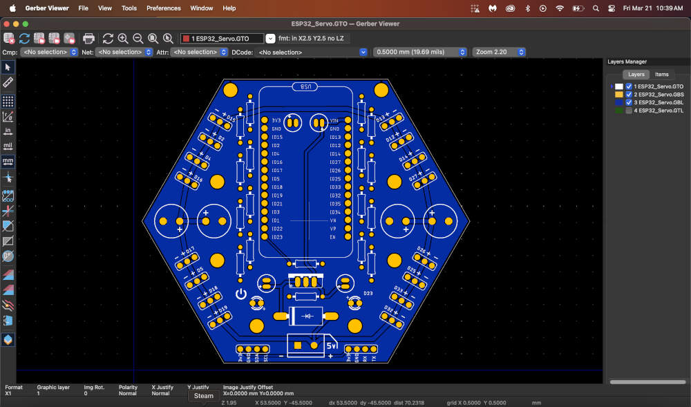
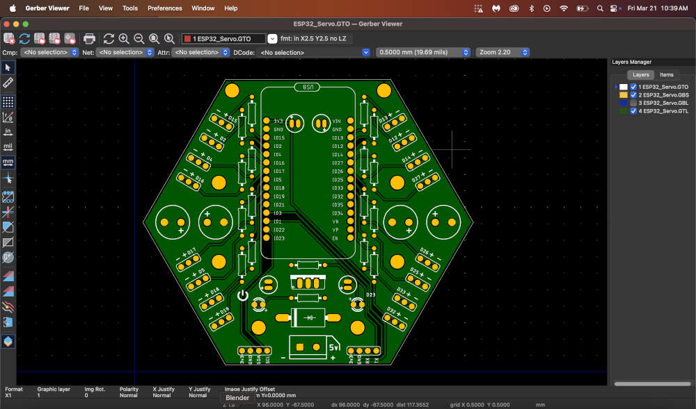
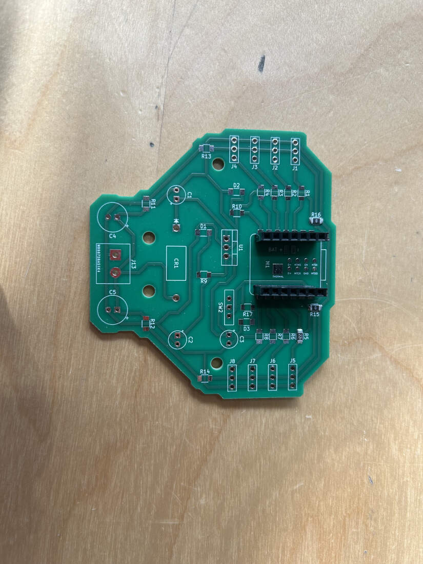
The Gerber files for this tutorial were available for download and I then used my Mac's Gerbview to inspect the layers of the board to gain a proper understanding of circuit paths. The images are located above.
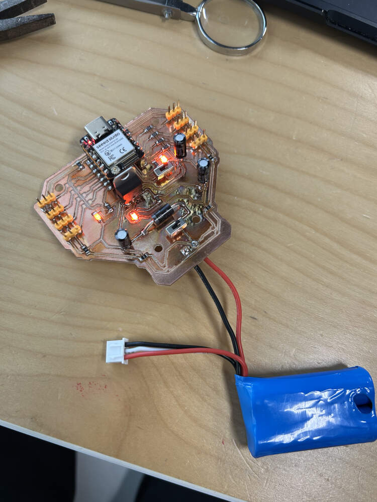
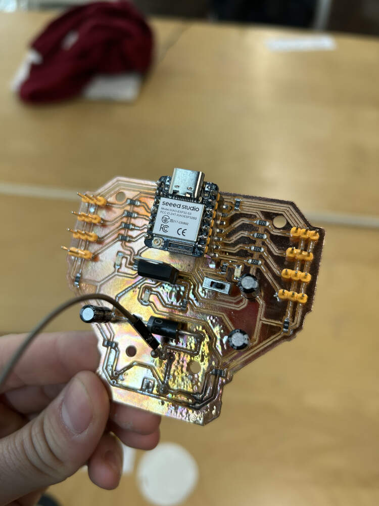
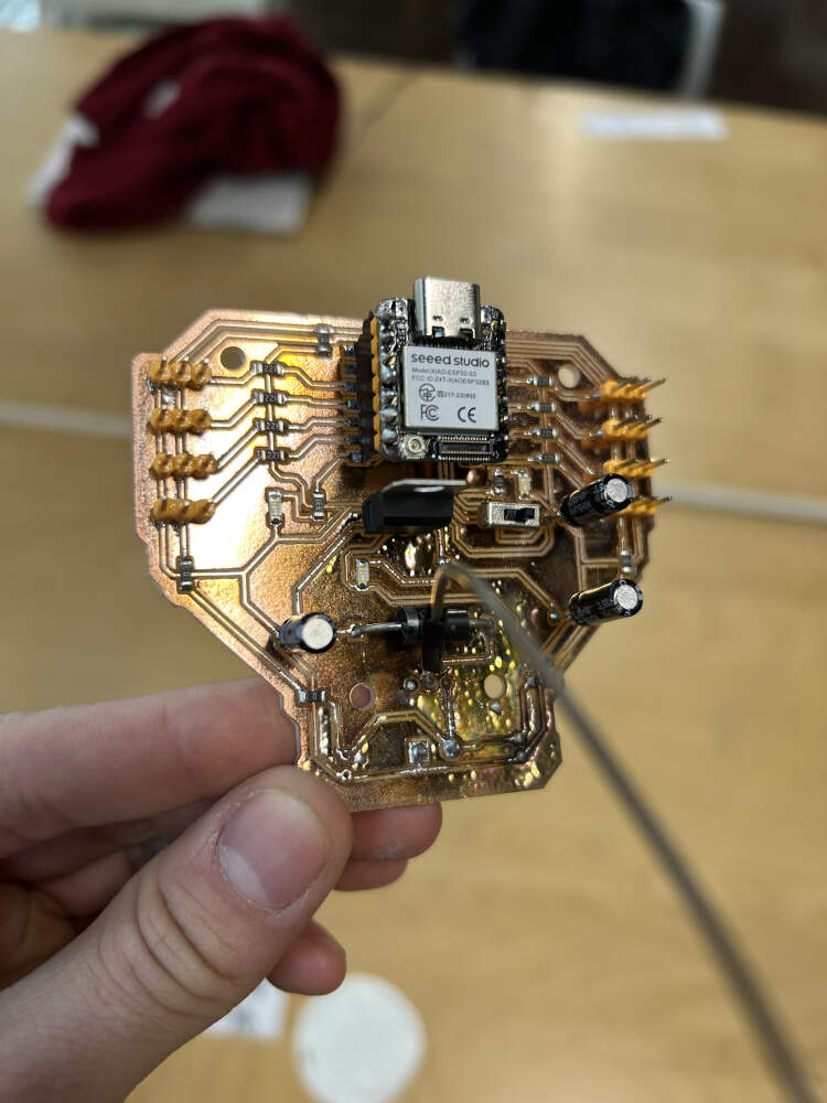
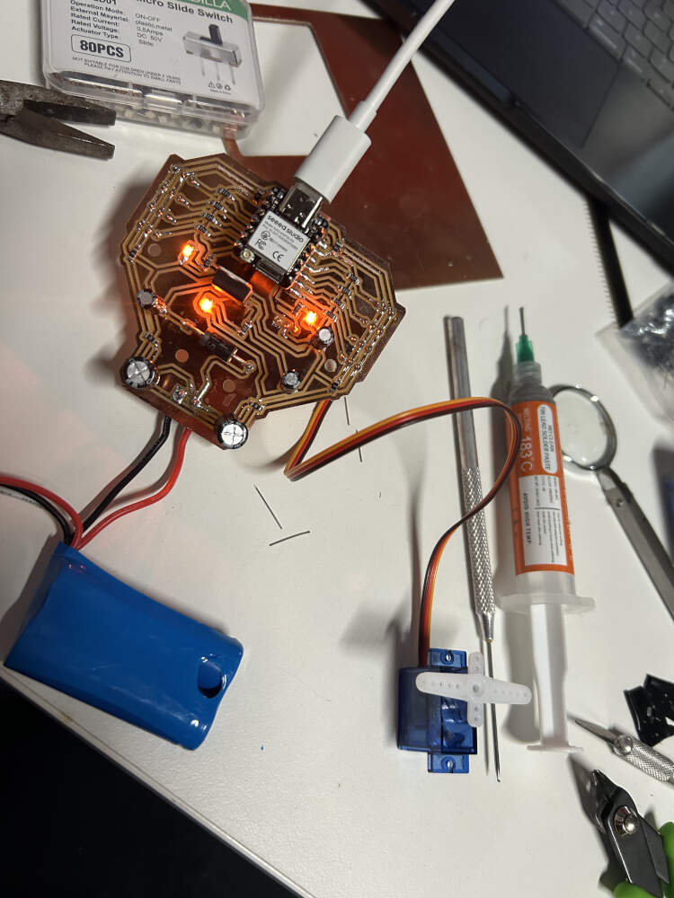
The new board featured many of the components I had already discussed above, or had used in my previous boards, but a new component that I added to the design was the slide switch. At this point in time I added two onto the board. One was located right after the screw terminal allowing me to shut off power from the start of that circuit, and the second was located right before the microcontroller. The second one allowed me to prevent power from going to the controller in case it was connected to my computer, and the board connected to the battery to prevent any potential burnouts. This second switch was wired in a way that allowed power to flow from the battery to the microcontroller, but in the event that I did not have the battery wired into the board, I could flip the second switch and reroute power from the microcontroller (if powered) to the rest of the board for small scale testing with one or two servos.
I milled out my board and began soldering components. On slide 5 you'll see that the board is working just fine in terms of electrical flow. Slide 6 is where issues began. You'll see that the switch right after the screw terminal is missing. This is because of a combination of two things, close proximity of components, and hot air. The 470uf capacitors located close to the screw terminal required soldering, but in trying to fix them to the board, I accidentally blasted the switch with too much hot air causing its plastic parts to melt. I had LED's on the board telling me where electricity was actively flowing so when I reconnected the battery some of the LED's were off, so I panicked and started trying to figure out why my microcontroller was not on. I later discovered that an internally melted switch can no longer use the "ON/OFF" functions so I tried jury-rigging a wire from the ON portion of the switch to the power pin. Unfortunately this did not work either because I had replaced so many switches trying to figure out why power not flowing that I did not realize I had damaged the paths leading up to that particular switch. Blasting the board with hot air also meant I had burnt the copper on the my board. Admittedly, it looks pretty cool, but this also didn't help some of the paths on my board, either because solder go into areas I did not want it to, or because the copper lines broke under too much heat.
To avoid further issues with my board and soldering, I removed one of the switches. This helped prevent overheating and eliminated a redundant component. The remaining switch was reconfigured from an ON/ON to an ON/OFF setup by removing one of the circuit paths leading back to the power supply.
This change removed the option to power the board through the microcontroller when the battery was unavailable, but that functionality wasn’t necessary. The switch now controls power only to the microcontroller.
Since the first switch was removed, I wanted to retain the ability to cut power entirely. With an ON/ON switch, an external battery could send power directly to the microcontroller through the diode, or the long way around potentially shorting it unintentionally. The new configuration prevents that risk.
For this design, I widened the circuit paths from 0.5mm to 0.8mm and used a 1/32 bit for most of the cuts. The 1/64 bit was minimally used in this board. There was a stark difference between the two due to the wear on the 1/64 but the use of the 1/32 is a notable improvement in terms of time spent milling, spacing, and room for mistakes while soldering. I soldered the new board and tested it once it was complete. It worked perfectly.
WK10 Output Devices Documentation featuring Redesign
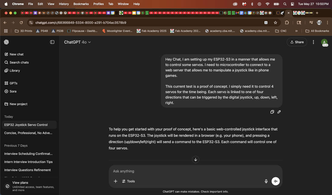
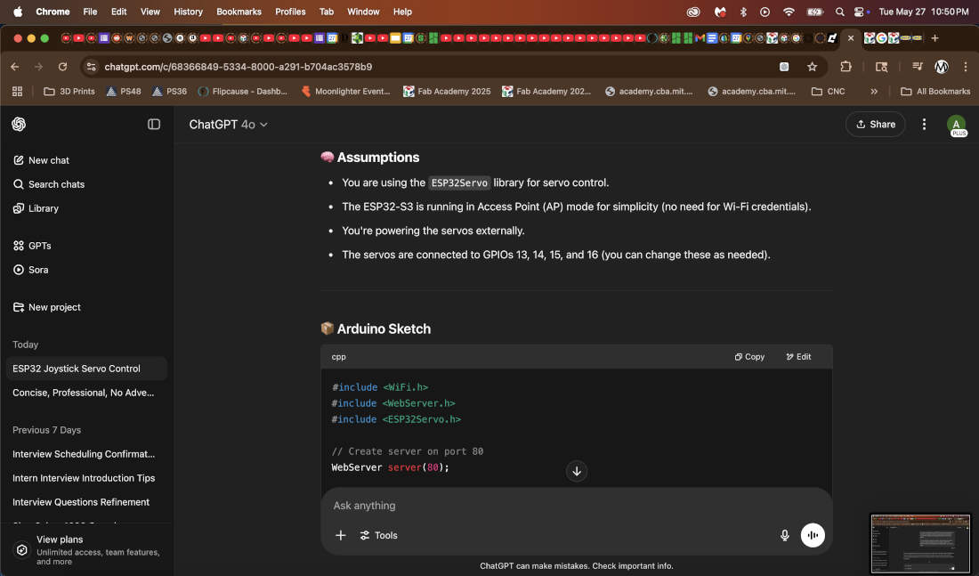
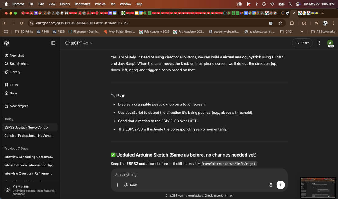
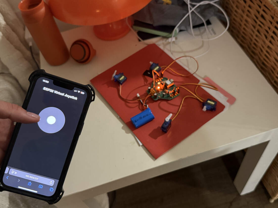
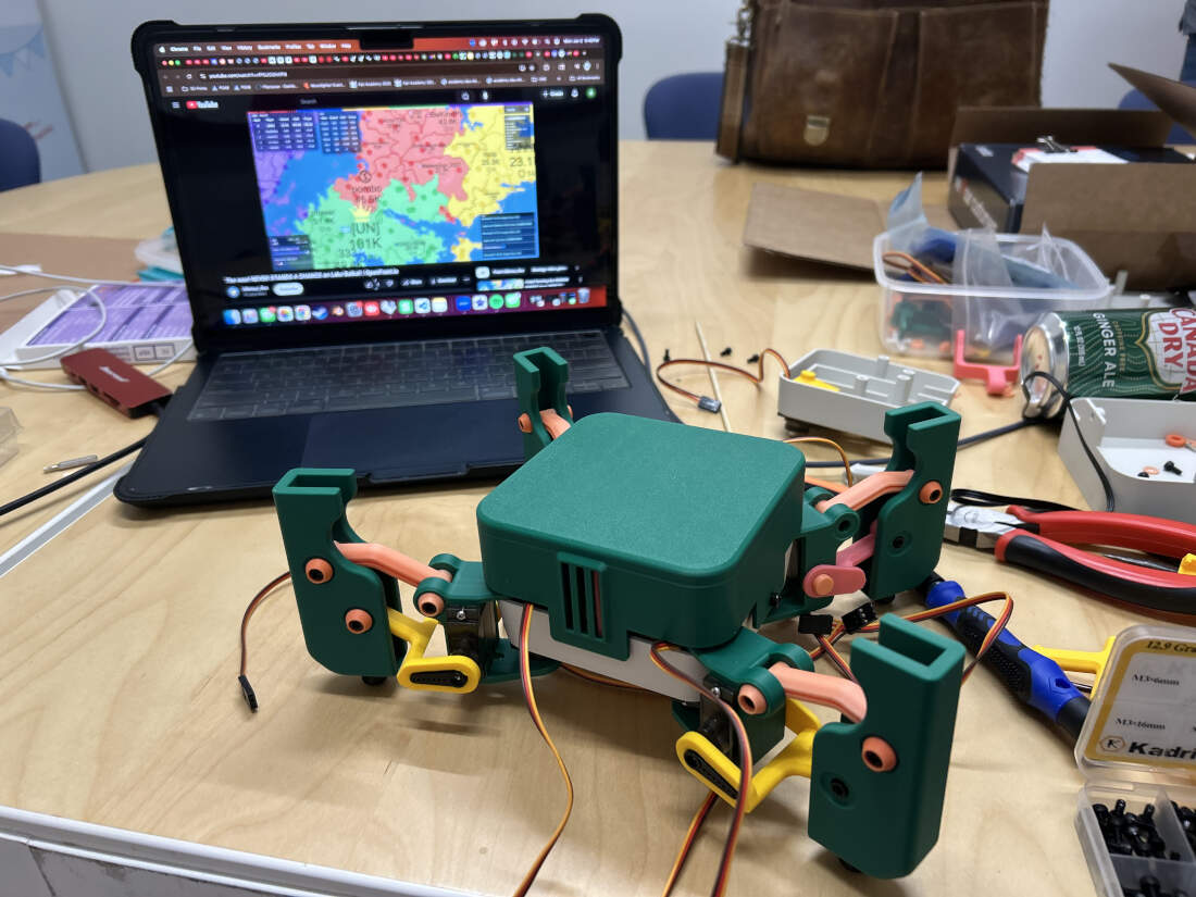
ChatGPT as always is a blessing. Even though my final project is not ready to be built I have used this as an oppurtunity to create a proof-of-concept[thanks Peter B^)]. My robot will be utilizing 8 servos, 2 on each leg to move around. Since the mechanical aspects of the robot are missing I decided to simply utilize 4 servos and assign each to a specfic direction. I directed ChatGPT to create a virtual joystick that could be used to control each of those 4 servos. Once the final project is built the joystick would control all 8 servos in intervals or simultaneously to move the entire robot.
I wanted to clarify that not only was Chat coding for Arduino but also coding in HTML for the webpage. I did not focus on connecting to wifi or worrying about IP's at this point but instead solely focused on testing out the HTML portion.
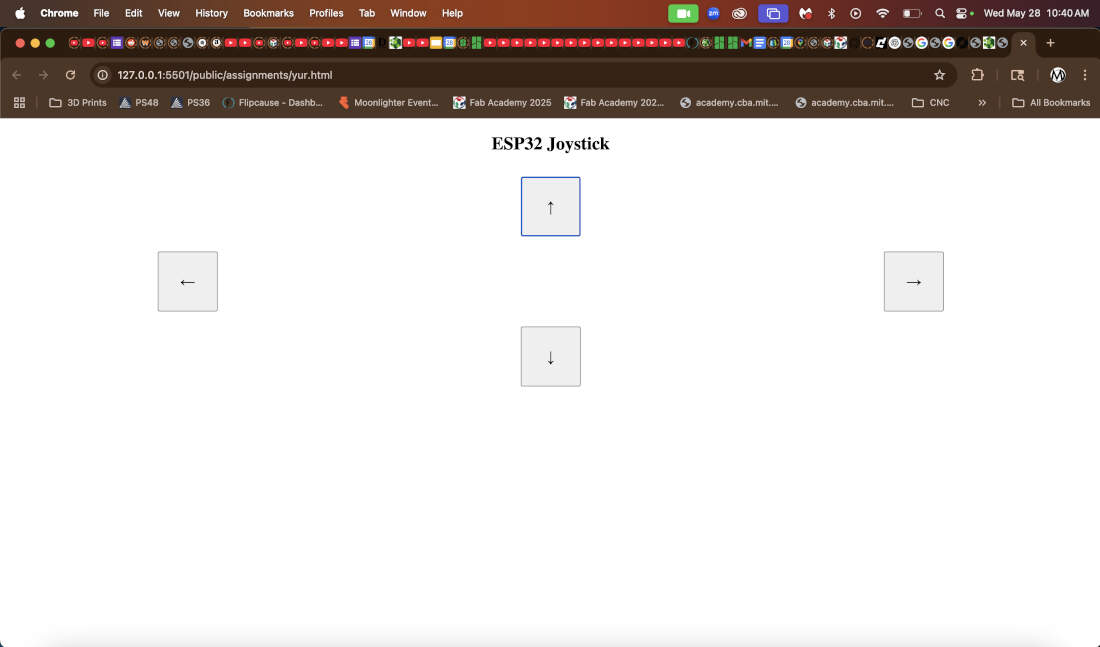
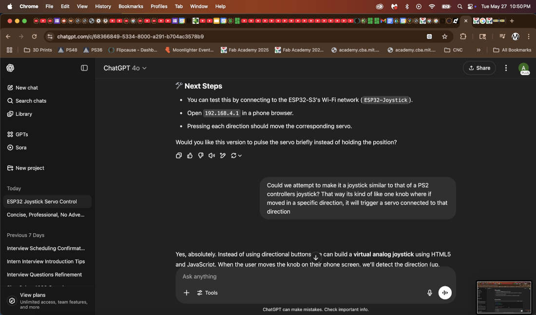
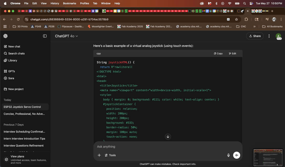
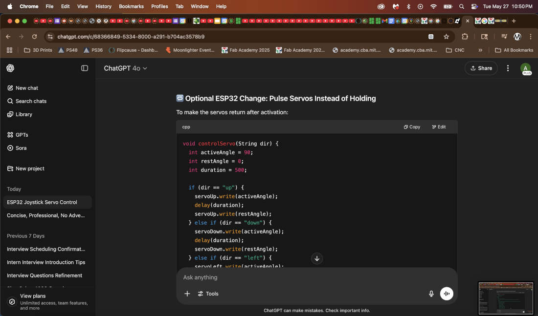
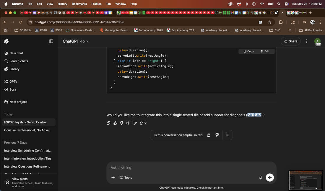
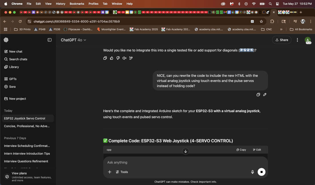
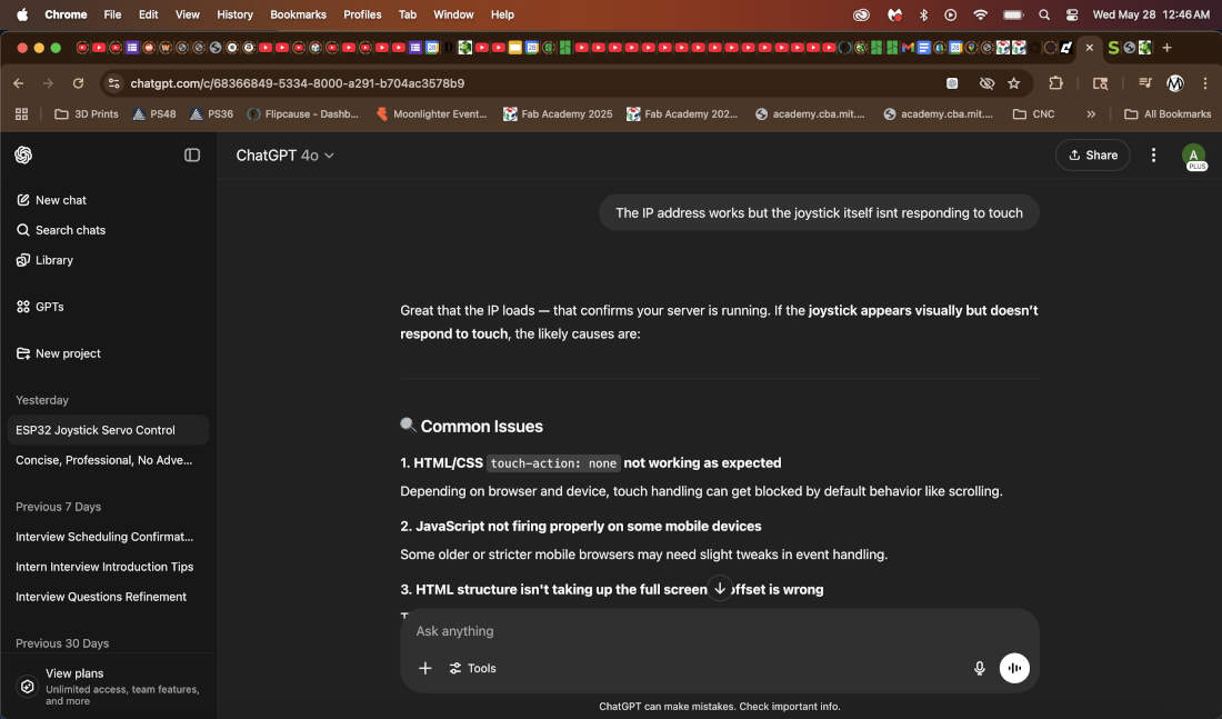
My first attempt in directing ChatGPT to get the results I wanted were not successful. It sort of understood what I wanted but instead of a joystick it gave me arrow keys. The second try it visually gave me what I needed but touch was not registering on my phone. So my third attempt was asking Chat to include the new HTML code in addition to editing the code to properly enable touch events and incorporating pulsing of the servos whenenever the joystick is active or inactive allowing the servos to move back in place when inactive.
The video above displays the UI results.
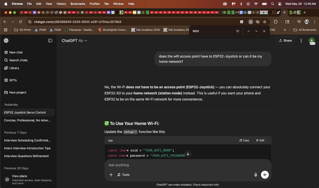
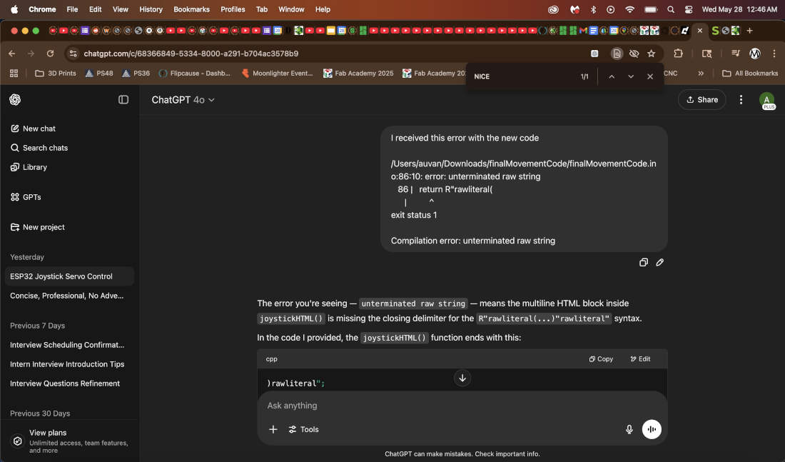
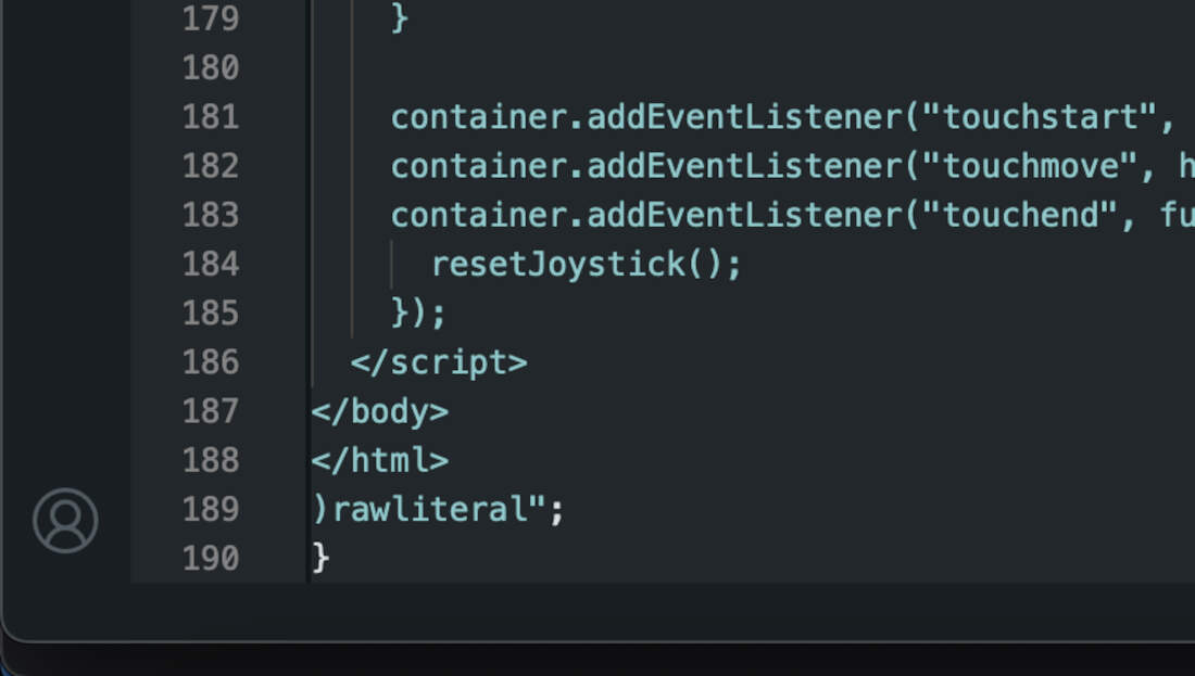
The second set of edits simply asked Chat to clarify the requirements of the WiFi network and password. I requested that Chat alter the code to allow me to utilize my own Wifi Network instead of an access point. Afterwards I received an error before fully being able to upload the code via the Arduino IDE. I asked ChatGPT what the error was about and it informed that the closing delimiter "rawliteral" was missing at the end. So I pasted it into the code and it fixed the uploading error. Fixing the error broke the touch functions so I asked ChatGPT to go over it again and it was successful in fixing it. I uploaded the updated code with the right WiFi network and password and went on to test my board.
For all of this to work the ESP32-S3 hosts a web server tied to an IP address while controlling 4 servos. I connect to this IP address via the web browser on my phone and via touch I control a virtual joystick which sends directional commands to each of the four servos.
Attached below you'll find the final code. Download available at the bottom of the page.
#include <WiFi.h>
#include <WebServer.h>
#include <ESP32Servo.h>

const char* ssid = "Fleet of Worlds";
const char* password = "Ringworld1970$";

Servo servoUp, servoDown, servoLeft, servoRight;
const int pinUp = 3;
const int pinDown = 7;
const int pinLeft = 5;
const int pinRight = 9;

WebServer server(80);

void setup() {
Serial.begin(115200);

servoUp.attach(pinUp);
servoDown.attach(pinDown);
servoLeft.attach(pinLeft);
servoRight.attach(pinRight);

WiFi.begin(ssid, password);
Serial.print("Connecting to Wi-Fi");

while (WiFi.status() != WL_CONNECTED) {
  delay(500);
  Serial.print(".");
}

Serial.println("\nWi-Fi connected!");
Serial.print("IP Address: ");
Serial.println(WiFi.localIP());

server.on("/", []() {
  server.send(200, "text/html", joystickHTML());
});

server.on("/move", []() {
  String dir = server.arg("dir");
  controlServo(dir);
  server.send(200, "text/plain", "OK");
});

server.begin();
Serial.println("Server started");
}

void loop() {
server.handleClient();
}

void controlServo(String dir) {
int activeAngle = 90;
int restAngle = 0;
int duration = 500;

if (dir == "up") {
  servoUp.write(activeAngle);
  delay(duration);
  servoUp.write(restAngle);
} else if (dir == "down") {
  servoDown.write(activeAngle);
  delay(duration);
  servoDown.write(restAngle);
} else if (dir == "left") {
  servoLeft.write(activeAngle);
  delay(duration);
  servoLeft.write(restAngle);
} else if (dir == "right") {
  servoRight.write(activeAngle);
  delay(duration);
  servoRight.write(restAngle);
}
}

String joystickHTML() {
return R"rawliteral(
<!DOCTYPE html>
<html>
<head>
<title>Joystick</title>
<meta name="viewport" content="width=device-width, initial-scale=1.0">
<style>
  html, body {
    margin: 0;
    padding: 0;
    background: #111;
    height: 100%;
    touch-action: none;
    overflow: hidden;
    color: white;
    font-family: sans-serif;
    text-align: center;
  }
  #joystickContainer {
    position: relative;
    width: 200px;
    height: 200px;
    background: #333;
    border-radius: 50%;
    margin: 100px auto 0;
    touch-action: none;
  }
  #joystick {
    position: absolute;
    width: 60px;
    height: 60px;
    background: #fff;
    border-radius: 50%;
    top: 70px;
    left: 70px;
    touch-action: none;
  }
</style>
</head>
<body>
<h2>ESP32 Virtual Joystick</h2>
<div id="joystickContainer">
  <div id="joystick"></div>
</div>

<script>
  const container = document.getElementById("joystickContainer");
  const joystick = document.getElementById("joystick");
  const center = 70;
  const maxDist = 60;
  let currentDir = "";

  function getDirection(x, y) {
    const dx = x - center;
    const dy = y - center;
    if (Math.abs(dx) < 20 && Math.abs(dy) < 20) return "";
    if (Math.abs(dx) > Math.abs(dy)) return dx > 0 ? "right" : "left";
    return dy > 0 ? "down" : "up";
  }

  function sendDirection(dir) {
    if (dir !== currentDir && dir !== "") {
      fetch("/move?dir=" + dir);
      currentDir = dir;
    }
  }

  function resetJoystick() {
    joystick.style.left = center + "px";
    joystick.style.top = center + "px";
    currentDir = "";
  }

  function handleTouch(event) {
    event.preventDefault();
    const rect = container.getBoundingClientRect();
    const touch = event.touches[0];
    let x = touch.clientX - rect.left;
    let y = touch.clientY - rect.top;

    const dx = x - center;
    const dy = y - center;
    const dist = Math.min(Math.sqrt(dx * dx + dy * dy), maxDist);
    const angle = Math.atan2(dy, dx);

    x = center + dist * Math.cos(angle);
    y = center + dist * Math.sin(angle);

    joystick.style.left = x + "px";
    joystick.style.top = y + "px";

    const dir = getDirection(x, y);
    sendDirection(dir);
  }

  container.addEventListener("touchstart", handleTouch);
  container.addEventListener("touchmove", handleTouch);
  container.addEventListener("touchend", function () {
    resetJoystick();
  });
</script>
</body>
</html>
)rawliteral";
}
Everything went perfectly. Each direction on the joystick responded to its assigned servo. I am looking forward on working on this further to finalize my robot.
WK14 Interface and Application Programming Documentation
Hardware/Battery -
Some of the purchased bits needed to finalize my project. You'll see them being used throughout. The items are -
- Rubber End Caps for the Legs
- M3 Hex Bolts
- M3 x 20mm Standoffs for Leg Actuation/Movement
- 7.4v 800mAh Lithium Battery for Power
- M3 Heat Set Inserts
- M2 Heat Set Inserts
- M2 Screws
PCB Board -
My board design had been finalized and tested in previous weeks. I had put in an order through PCBWay to obtain "final" versions of my design. I soldered all necessary electronics components to have it functioning like the milled version.
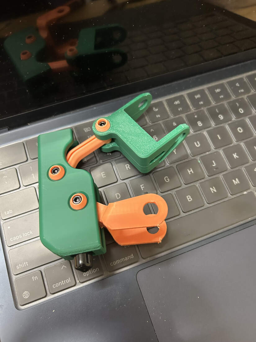
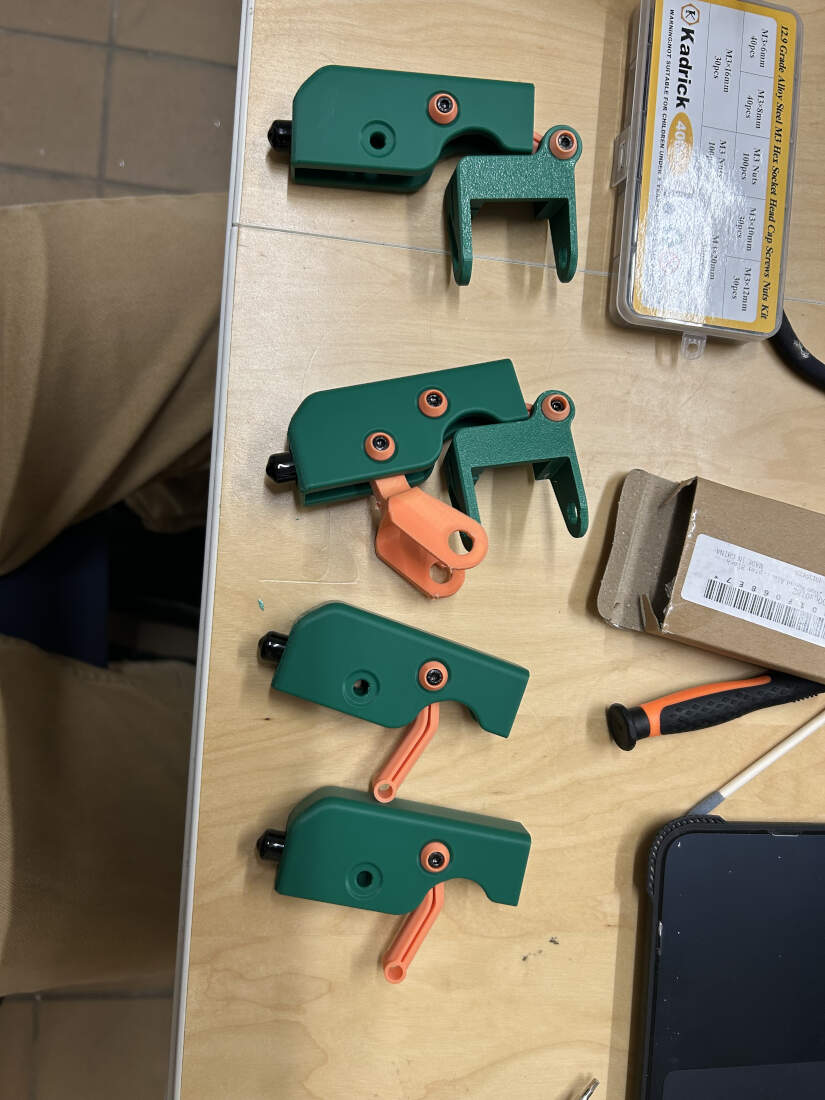
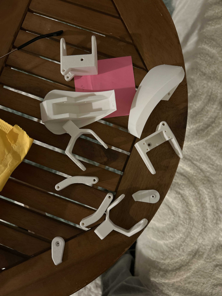
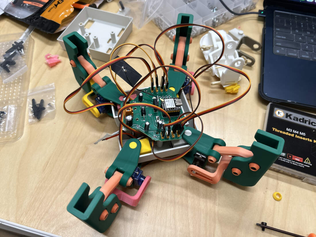
Legs -
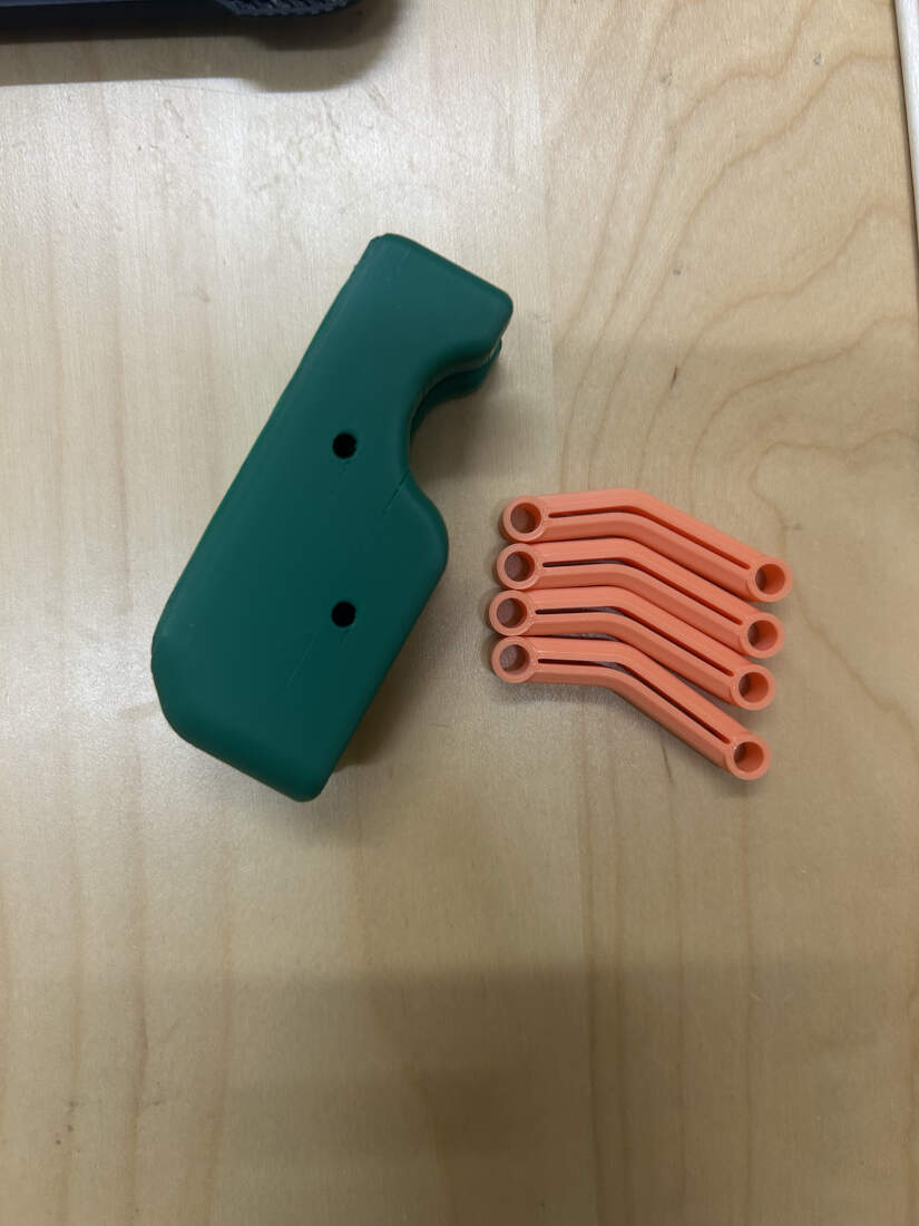
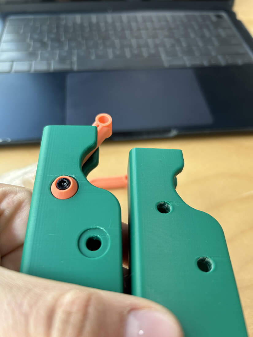
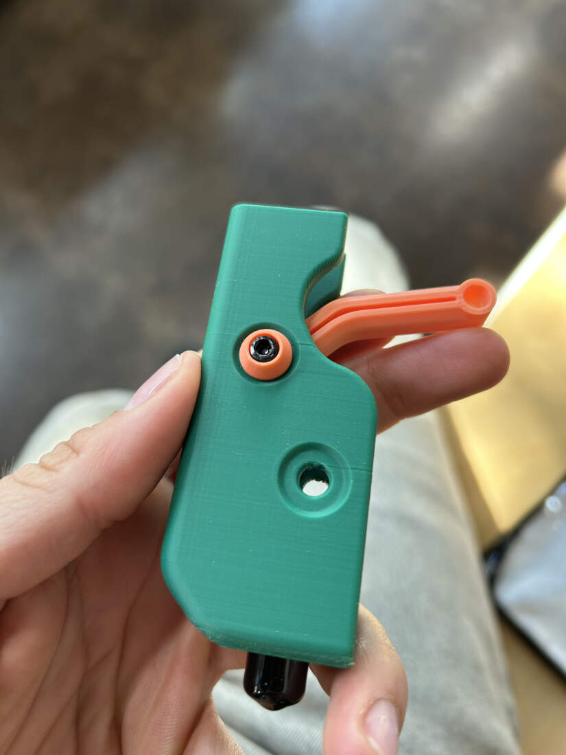
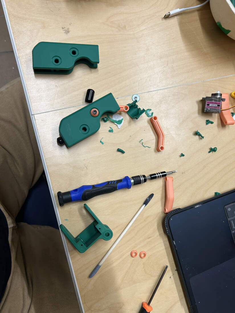
Legs started off really simple but were graudally developed to account for the hardware that was being implemented. Recesses were boolean differenced into the model to create a nice detail/semi-flush area to allow for a tapering bolt cover. This accomplishes a few things by covering the majority of the bolt, any possible standoff exposure, and further hiding any print artifacts created when printing overhanging curves. Rubber end caps are press-fit below. Standoffs and bolts further implemented to hold other parts of the leg. Some of these parts, seen in slide 5, require further development (orange bit at bottom, and rightmost green bit). They require resizing to fit the plastic arm bits that attach to the servos as seen in slide 7. Last slide shows various different versions that I went through to get the swiveling portion of the leg correct as needed by the rest of the robot.
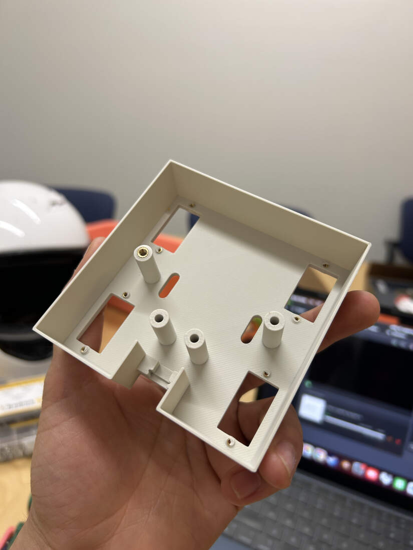
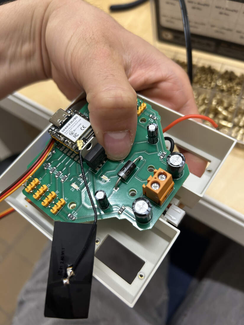
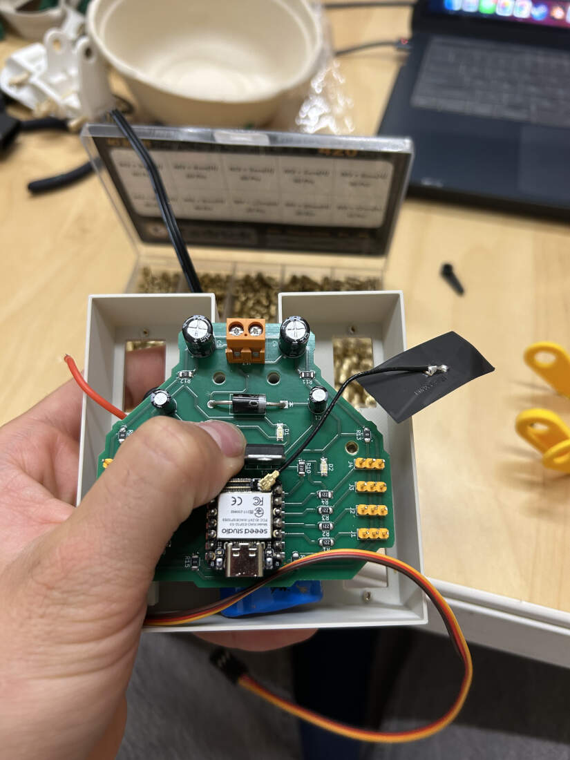
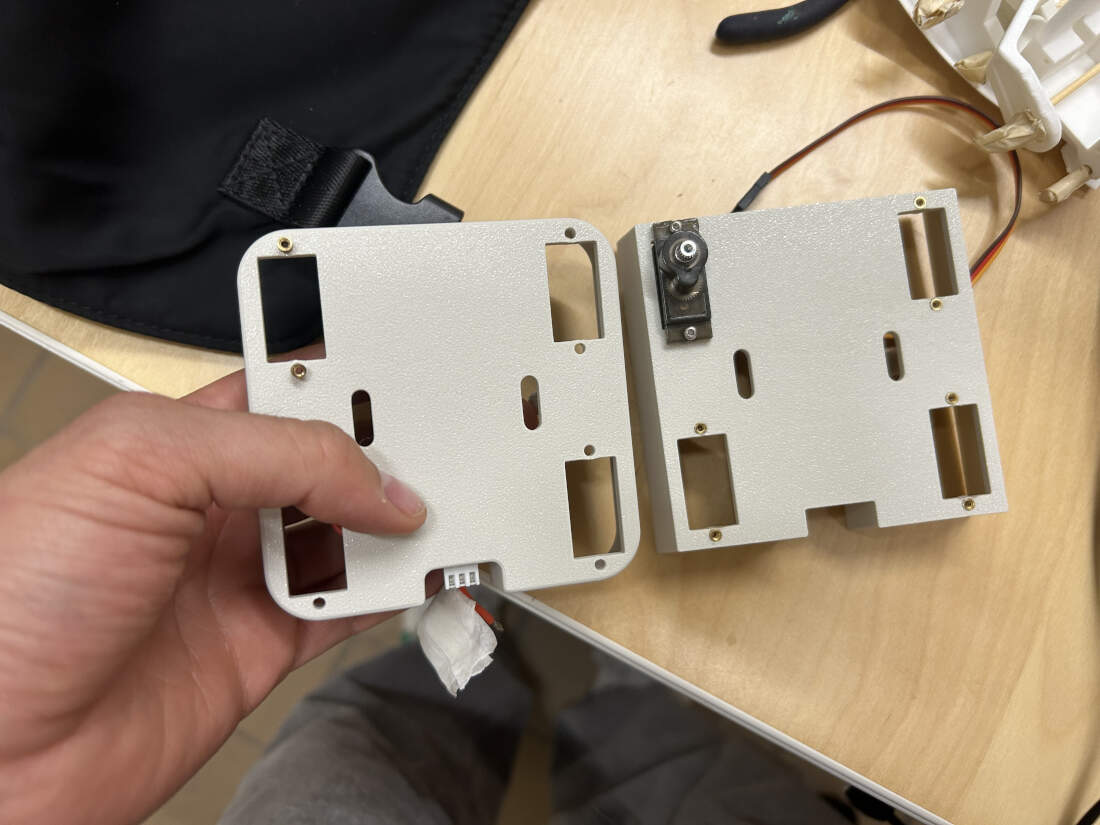
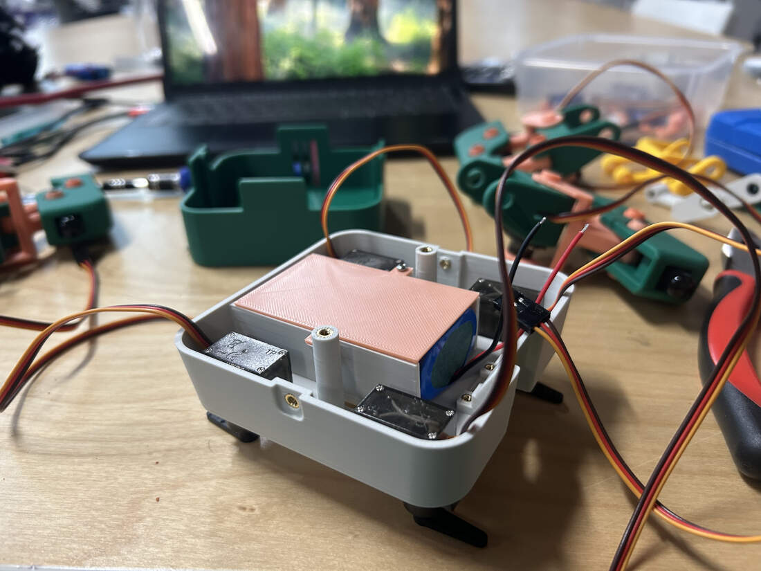
Chassis -
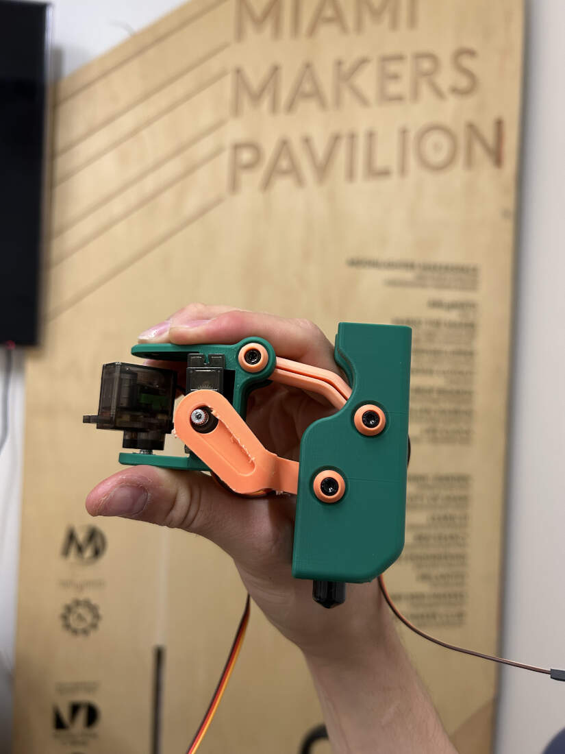
First version of the chassis modeled. Heat set inserts tested. Support standoffs for PCB require wider holes. Inserts for servos are fine as they are. I tested the placement of the PCB. While it aligned perfecetly fine with the printed standoffs, you can see that the way the first chassis was modeled would cut off access to the screw terminal on the PCB. This is something to fix. Thankfully the area I modeled to hold the battery's charging cable was good enough to hold the male cable head in place. This needed additional work though as I did not want a gaping hole over the "charging cable holder" in the final version. The chassis was a good WIP though. I was able to attach the leg onto the chassis. The rectilinear chassis created issues with the movement of the leg because its sharp corner would scratch a portion of the leg when it swiveled creating friction. This would be fixed. If looking closely at the last slide, you can see the green of the leg surrounding a bone white circle. This bone white circle is a part of a "ball and socket joint" I made as a cap to place over the servos. The ball is the cap, and the socket is the circular hole in that portion of the leg. I suppose that portion of the leg can be seen as one of four pelvises. Progress made on the joints will be seen below.
Ball and Socket Joints -
The first version did not fully encompass the servo. One of the sides was open. This would cause it to slip off the servos. To solve this issue the walls were extruded to be longer and they encompassed all 4 sides now. The tolerance was so good it could be press fit so the part would stay firmly in place over the servos.
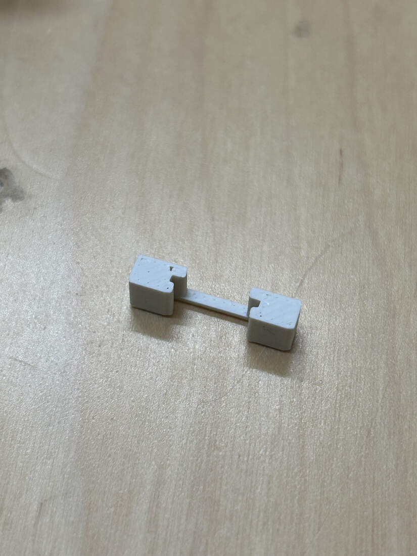
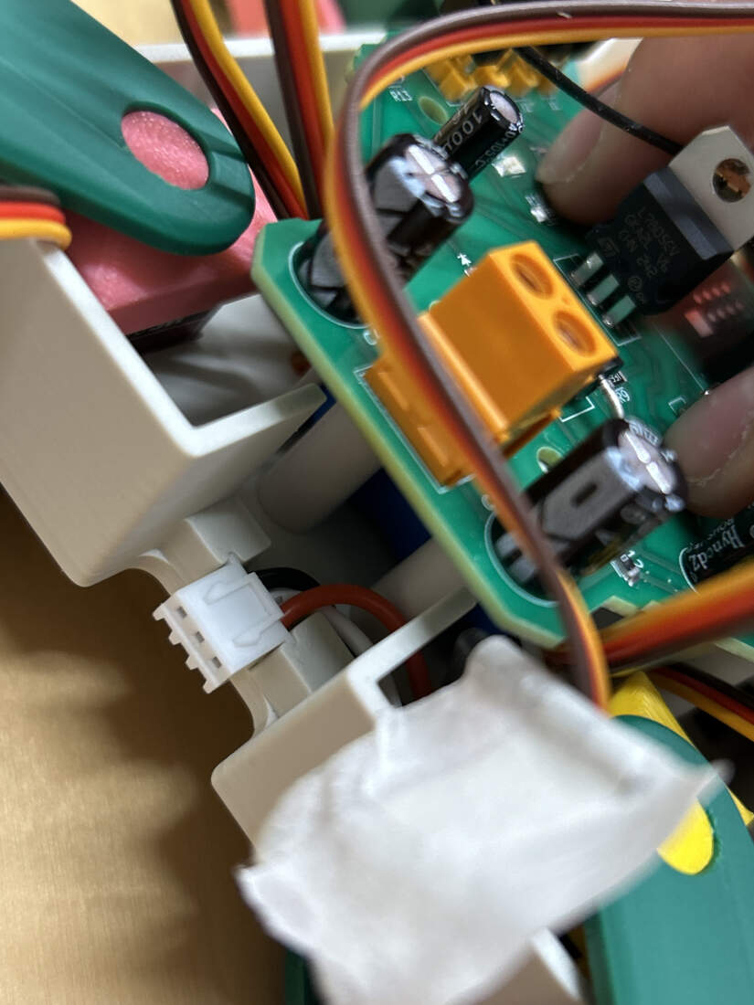
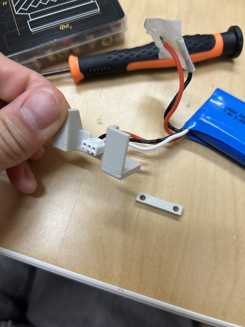
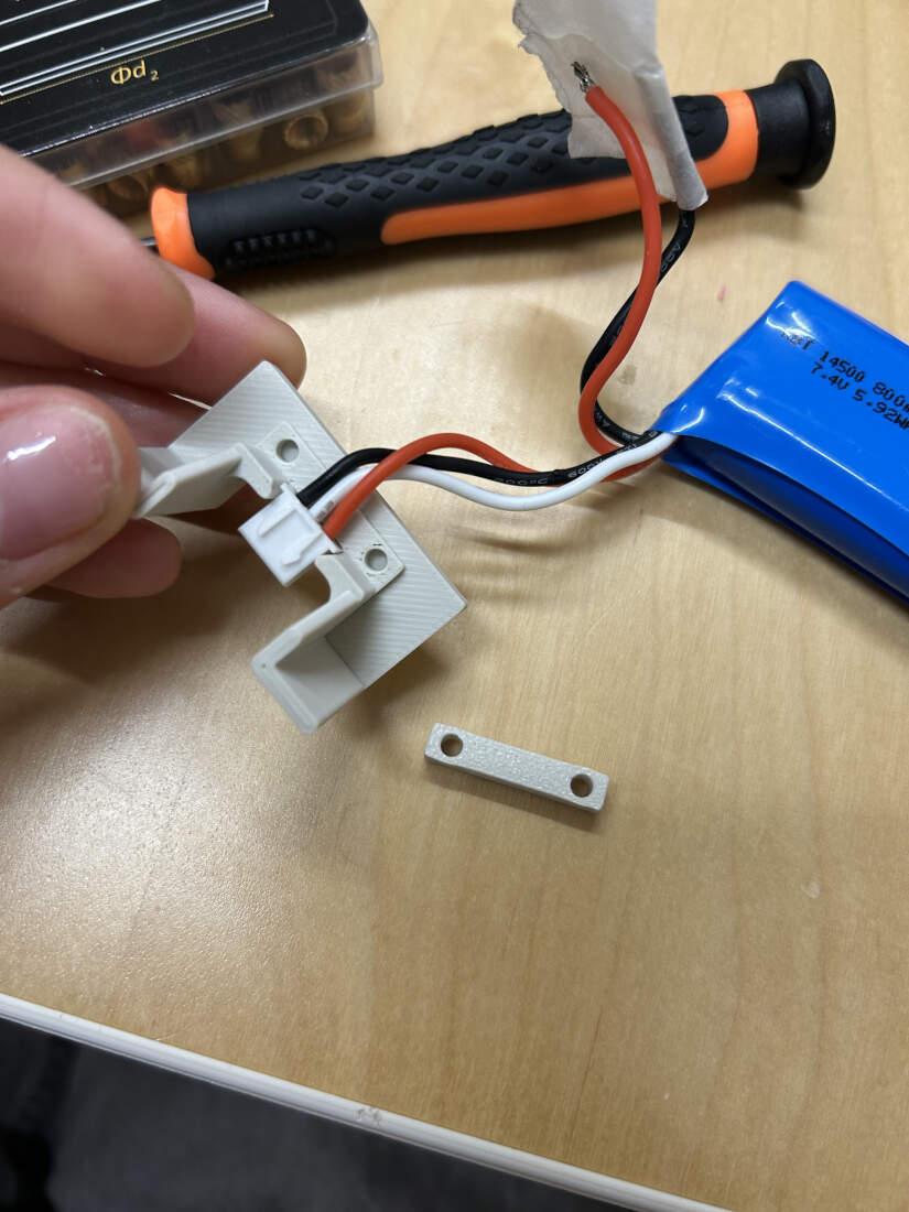
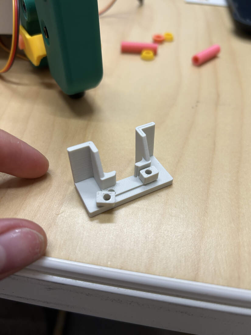
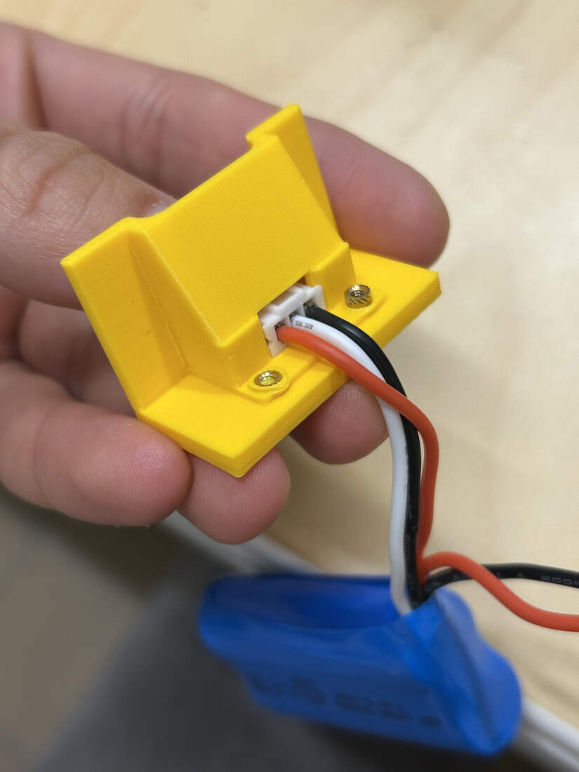
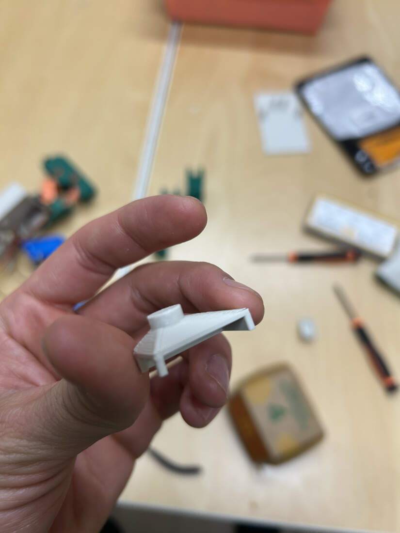
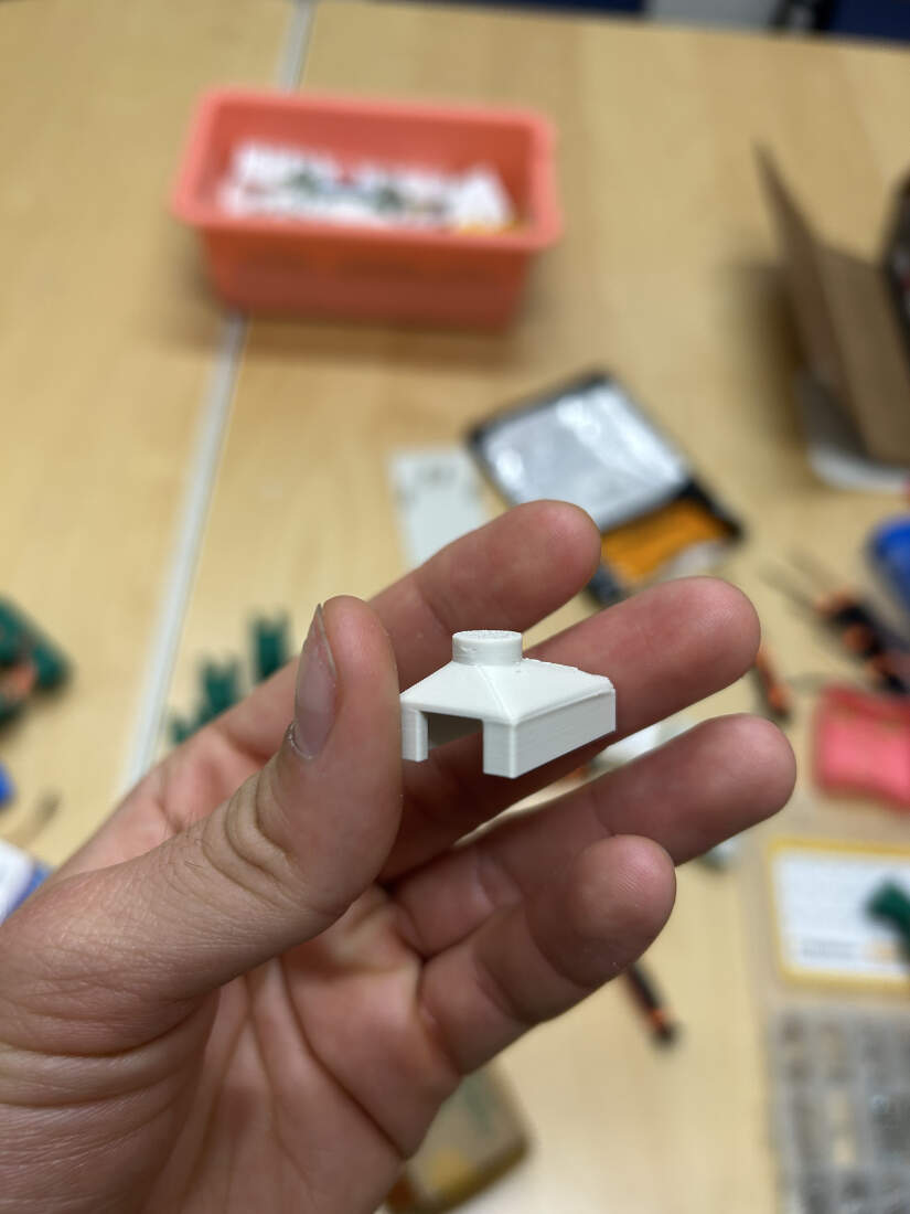
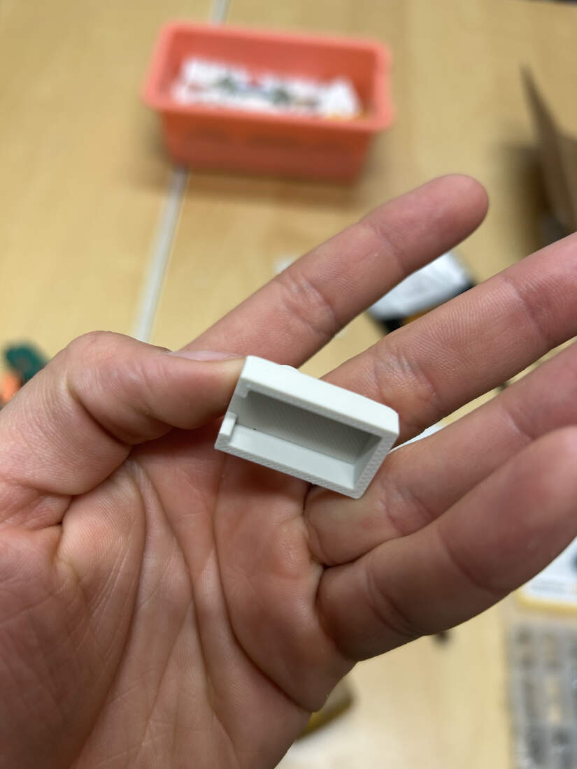
Charging Cable Holder -
The first version of the holder started of as a small separate piece to test tolerances. It thankfully worked on the first try as I used calipers for measurement. The second version was put in the first chassis. To solve the PCB cable clearance issues, this area was further developed while also trying to match the rest of the design. This portion of the model was also cut or trimmed out to save on time and increase my focus on just that area. I decided to create two other areas to include heat set inserts in and printed a long rectangular piece to screw in place allowing me to hold the cables male head in place. I forgot the cable was in the way of setting the entire rectangle down so I cut it down into two separate blocks. After seeing that that worked I then included the overhanging wall over the cables head to give off an enclosed appearance. Those inserts did not fully fit but thats because I did not extrude the surface high enough so I did that for the final chassis model.
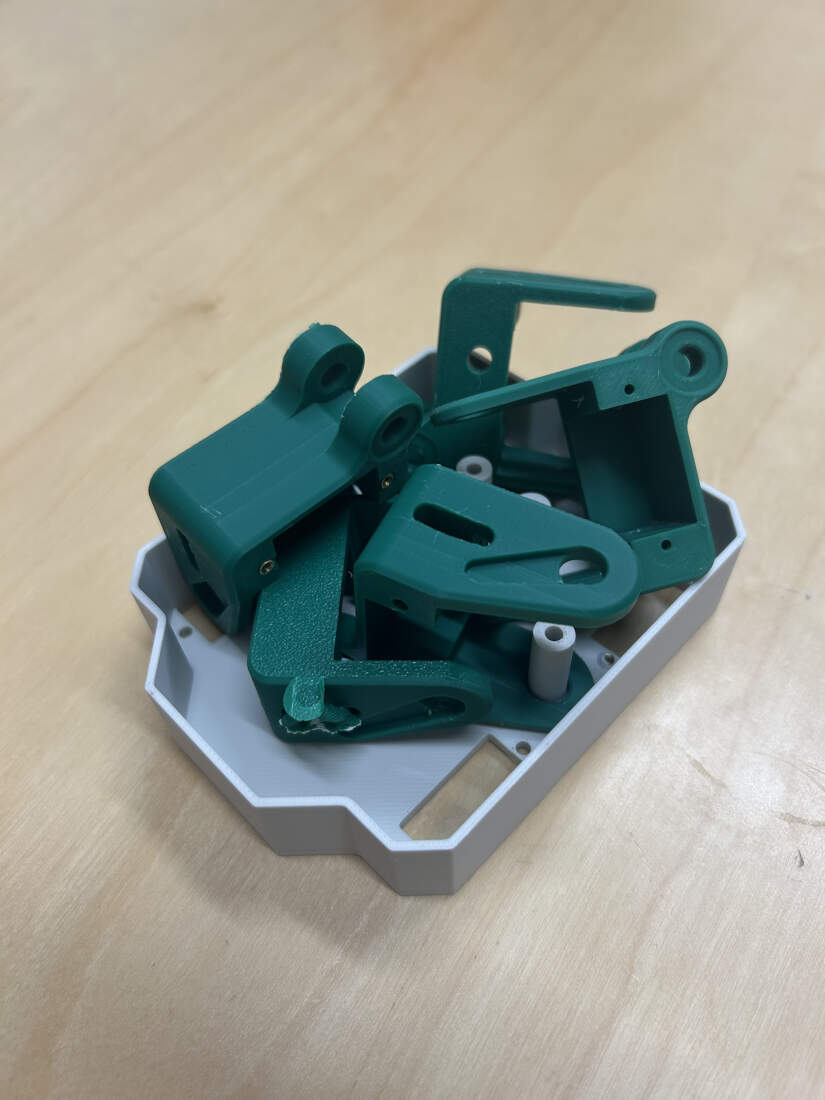
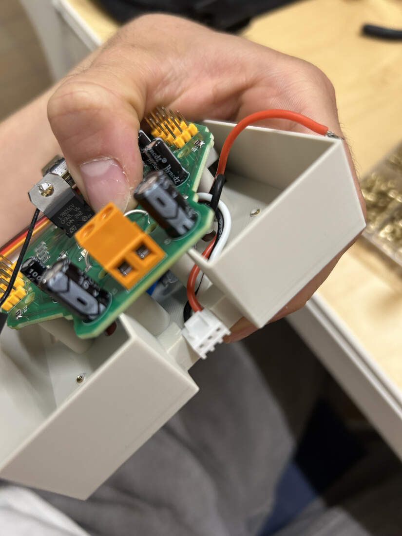
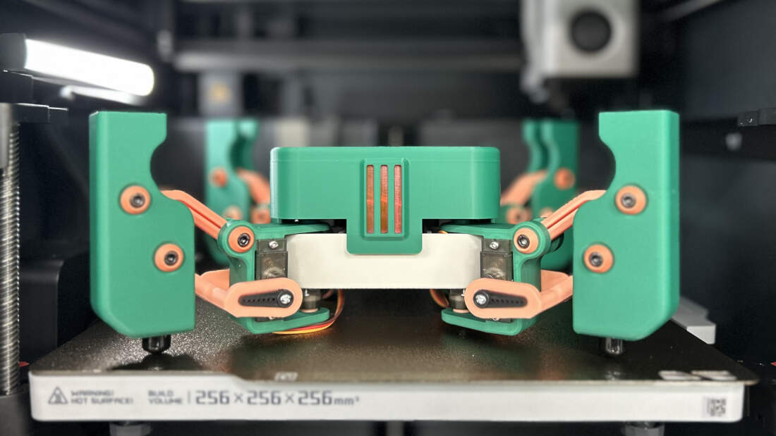
Chassis V2 -
New chassis with rounded corners being tested. Swivel movement of the legs is now uninterrupted. Various ball and socket joints printed and being used for the legs. All four legs fit on the robot just fine. PCB can mount just fine, still has the clearance issue but that is being fixed soon. Cap to hide electronics being developed soon.
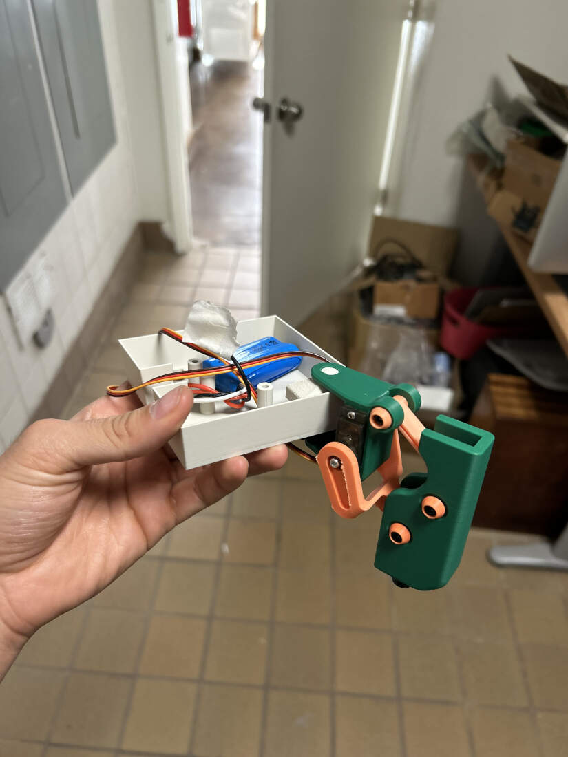
WK15 System Integration Documentation
Printed a cap for my robot to protect its internal parts. Features 3 slits at the front that will have laser cut acrylic.
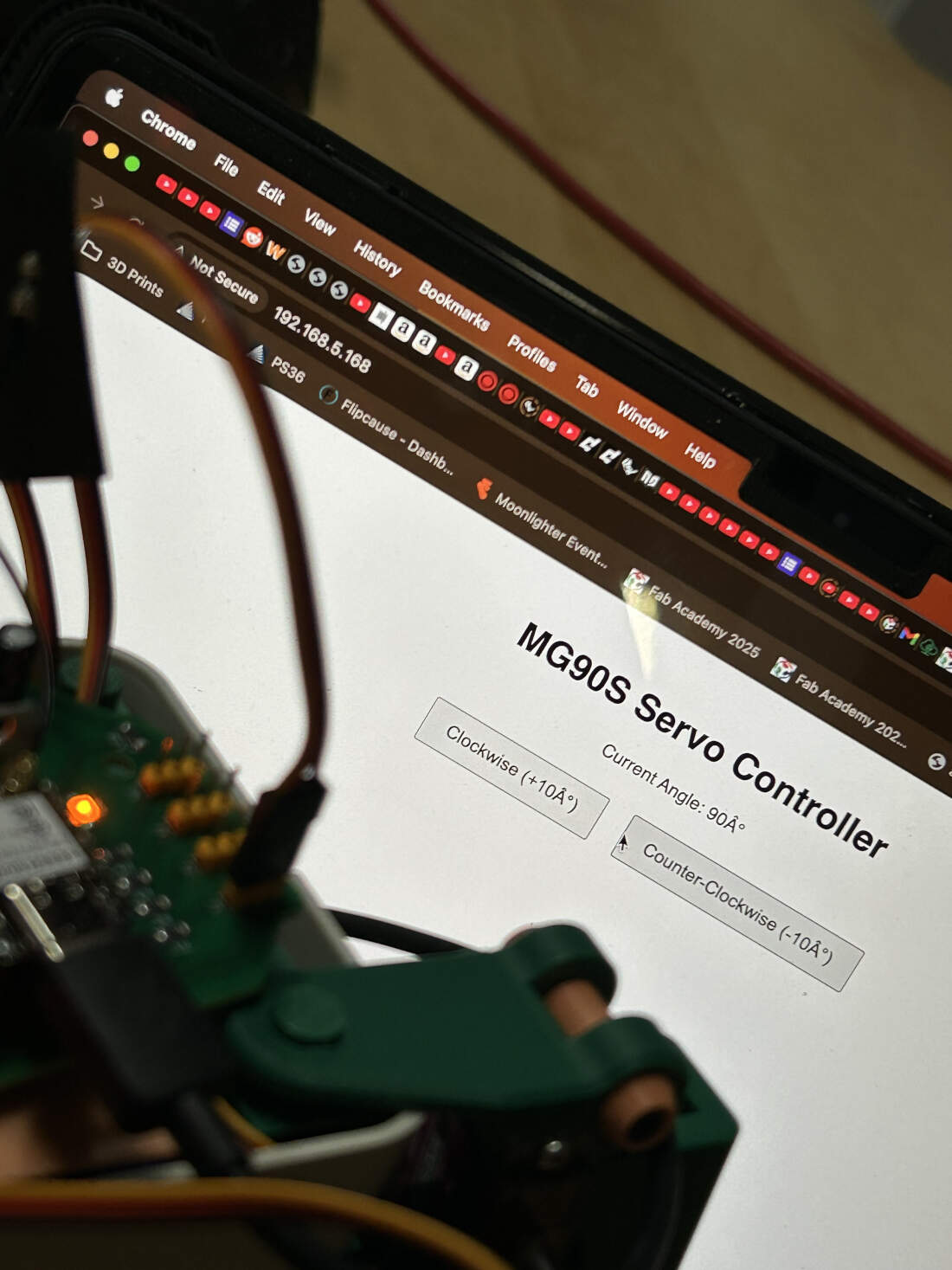
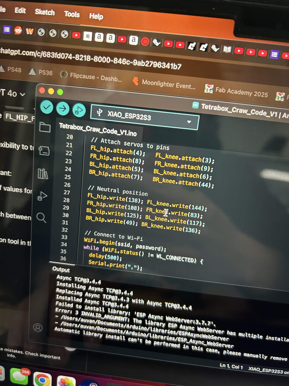
ChatGPT was used to develop a code/interface framework to test the various angles servos could be positioned in. Using this code, servos were positioned at ideal angles. Those angles were then used as a basis to test movement. A new code was developed with ChatGPT to make the robot walk. This could assigned each servo to its own leg, broken down into two parts, the knee, and the hip. Each servo would have its resting position and from there they would have their forwards positions. As seen in the video, the interface of the new code allows me to edit the angle of the servos/legs using the sliders. Then at the bottom of the screen I am fed back information about the servo/leg angles because the exact angle of the leg is updated to the closest degree possible.
As I received feedback on my angle limitations and their positions I was further able to tweak the neutral positions in the code to improve the walk cycles.
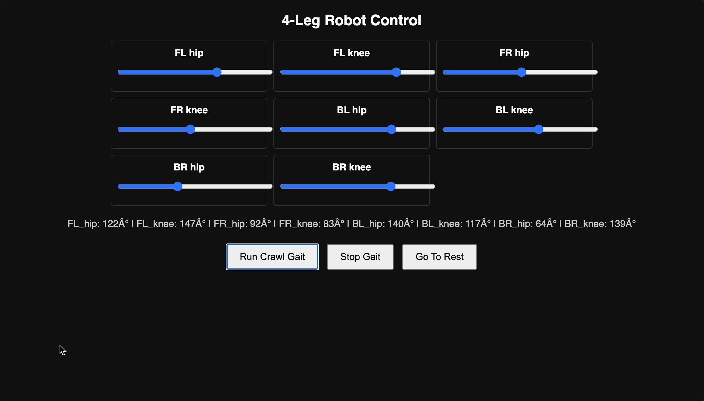
As I finished tweaking the walk cycle I soon after started tweaking the interface for a cleaner and more informative experience. I used ChatGPT to reorganize what I started off with by renaming my interface and organizing each leg into its own column. I took the angle readouts at the bottom and I reorganized them into their appropriate row on each column, associating them with the part of the leg they belonged too. Additionally I added status lights at the bottom. Green being "active", yellow for "establishing" or "reestablishing" connections, and red for "inactive". The last two iterations of the interface involved changing the color of the buttons to differentiate them from each other and also shortening their names for similar reasons. I also added two more buttons for interacting with the robot. Unfortunately only the "leg raises" button works. "Jump" was not able to be programmed given the time constraints associated to the deadlines for this course.
I got on ChatGPT again and decided to switch up its legwork. Seeing how slow its gait was when going through its walking cycle using one leg at a time I decided to ask ChatGPT to alter the code so that it operated on two legs at a time instead. This meant that one pair of legs diagonal from each other would move first and then the second set would take its turn and repeat until told otherwise. You can see the improvements in the first two videos. The second set of videos displays a far more fluid walk cycle. This was again, further improved upon by using AI. You can see the difference in both sets of videos. The first set looks rather stiff while the second set shows the robot "organically" bobbing and weaving across the table.
As mentioned earlier, I was able to use ChatGPT to incorporate a Leg Raises button into the interface and was able to use it to program these motions into the robot. The sped up video above demonstrates this.
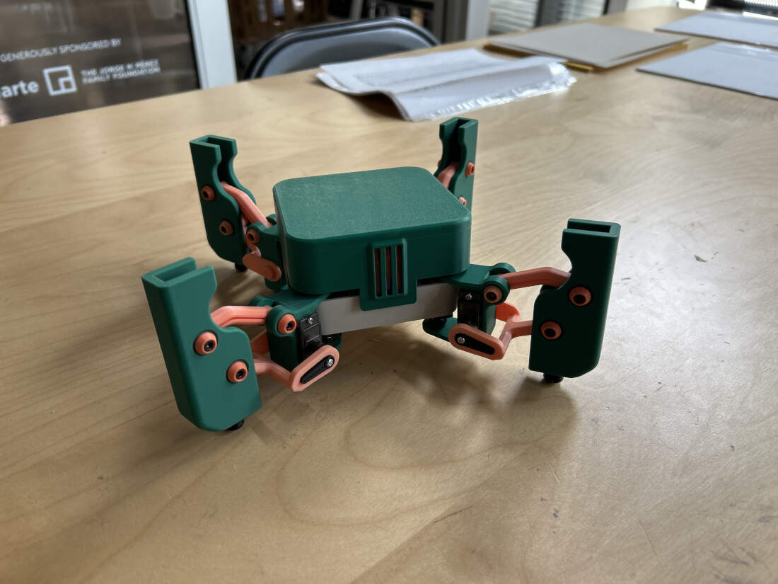
Final look of my final project. I've never built my own robot but I'm quite happy with this as my first attempt.
The project began for personal reasons but after some thought it would be a benefit to our educational programs to show kids what they can do with basic to intermediate materials and components. Additionally it serves as a nice way to show off what our FabLab is capable of producing. It is entry-level enough that beginners could use it as an introduction into robotics but advanced enough that people can build upon such ideas. Exposure of the project through the space and over time would allow it to potentially impact many of the kids and adults that come to our space. To fund the project, we'd simply have to streamline the design further to minimize the various different types of parts and hardware that is needed. From that point forward we can build multiple robot kits. There is no business plan. I have no interest in selling this project. The type of licenses that would apply to this would be an MIT License.
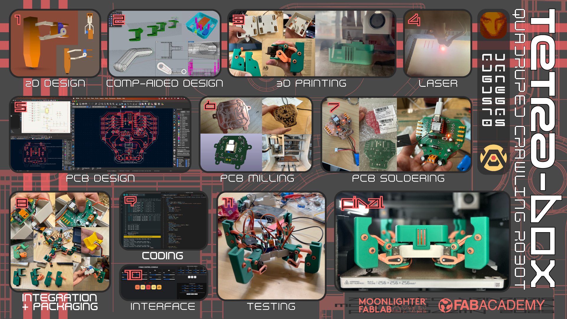
Attached above are my presentation board and my video.
Below you'll find a list of materials I have used for this project.
Microelectronics Components -
$6.99 - SB560 Diode
$8.45 - 01x02 Screw Terminal
$15.49 - 100uF Capacitor/470uF Capacitor
$6.09 - 0 Ohms Resistor (SMD)
$7.79 - 220 Ohms Resistor (SMD)
$8.49 - 330 Ohms Resistor (SMD)
$5.73 - 01x03 Vertical Pin Headers
$5.99 - Micro Slide Switches
$8.70 - 7805CV Voltage Regulator
$7.99 - R-1206 LED's (SMD)
$7.99 - Seeed Studio XIAO ESP32-S3
$10.99 - 7.4v 800mAh Lithium Battery
$27.99 - MG90S 9G Servo Motors
3D Printing -
$19.99 - Any Bambu Labs PLA Filament
$19.99 - Any Bambu Labs PETG Filament for Support Purposes
Hardware
$8.99 - M2 Screw and Nut Assortment
$7.99 - M3 Screw and Nut Assortment
$9.98 - M2 Heat Set Inserts
$17.99 - M3, M4, M5 Heat Set Inserts
$9.59 - M3 x 20mm Standoffs
Acrylic -
FREE - 1/8 Acrylic Sheet (scraps)
Below you'll a lin k to WK17's application and implications for comparison to the following questions below. You can see it as a before and after. An idea versus the reality.
WK17 Applications and Implications
What does it do?
It is a small tetrapod (four-limbed) "spider" robot. It connects wirelesslyto an IP address that controls movement. It's a fun project that could supplement Moonlighter's educational programs to show off what you can do with a bit of design thinking and simple robotics.
Who’s done what beforehand?
Answered in WK17 Documentation and on this page.
What did you design?
Designed my own PCB, designed interface, programmed code and HTML myself. The robot has a strong mechanical basis to one of my inspiration sources(iolly 2DOF by Erik Lely) with various alterations to those existing STL's allowing me to either alter the models aesthetically or alter them mechanically for my circumstances or both. Some of these mechanical alterations relate to integration and pacakging, form factor altering mechanical movement and accomations being made to make it happen, lacking the same servos or same hardware and having to compromise with what I had/have.
What sources did you use?
My sources were my two sources of inspiration. They helped inform the PCB design by understanding what components are needed or provided a mechanical foundation.
What materials and components were used and how much did they cost?
Answered above and on WK17 Documentation.
Where did they come from?
We have many of these materials within our FabLab. The battery, some of the electronics. and most of the hardware required online ordering.
What parts and systems were made?
The robots packaging, legs, the PCB, code, superficial design elements.
What processes were used?
3D Printing, Laser Cutting, CNC Milling for the PCB, 2D and 3D Design.
What questions were answered?
It walks. Its holds itself together. It looks cool but of course its subjective. I did not modify pre-existing code out there to benefit me and the functions of my project which is fine because I was able to figure something out for myself through ChatGPT. I modified pre-existing mechanisms/3D models in a manner that suits my circumstances but also looks good on paper and when printed. Last answer is the most important, but essentially the robot does look cool. The color scheme adds to it.
What worked? What didn’t?
The walk worked. Integration worked. Cool factor worked, its like a miniature crab insect furnace on legs. Outsourced hardware helped a lot. What didn't work were certains aspects of interfacing and code. Orignally I wanted to use a digital joystick to control the movement of the robot but the reality is that simply programming a simple walk cycle for your robot to move forward is complicated enough as it is. Having to do it in as least four directions ensuring that it moves smoothly is quite the challenge. This is why I resorted to a command based interface instead. It allowed me to complete my project in addition to allowing me to learn about the complexities of robotic movement in relation to coding and programming.
How was it evaluated?
On whether it walked forward given my inexperience in robotics.
What are the implications?
I don't really know how to properly answer this. I suppose the conclusions that can be drawn from this projects implications is that small scale robotics projects are possible on smaller budgets. The BOM for this project could be further improved upon to reduce costs too which would probably aid the previously brought up implication further.
Copyright 2025 Augusto Vanegas - Creative Commons Attribution Non Commercial Source code hosted at gitlab.fabcloud.org