


Individual Assignment:
- Use an EDA tool to design a development board that uses parts from the inventory to interact and communicate with an embedded microcontroller.
Group Assignment:
- Use the test equipment in your lab to observe the operation of a microcontroller circuit board.
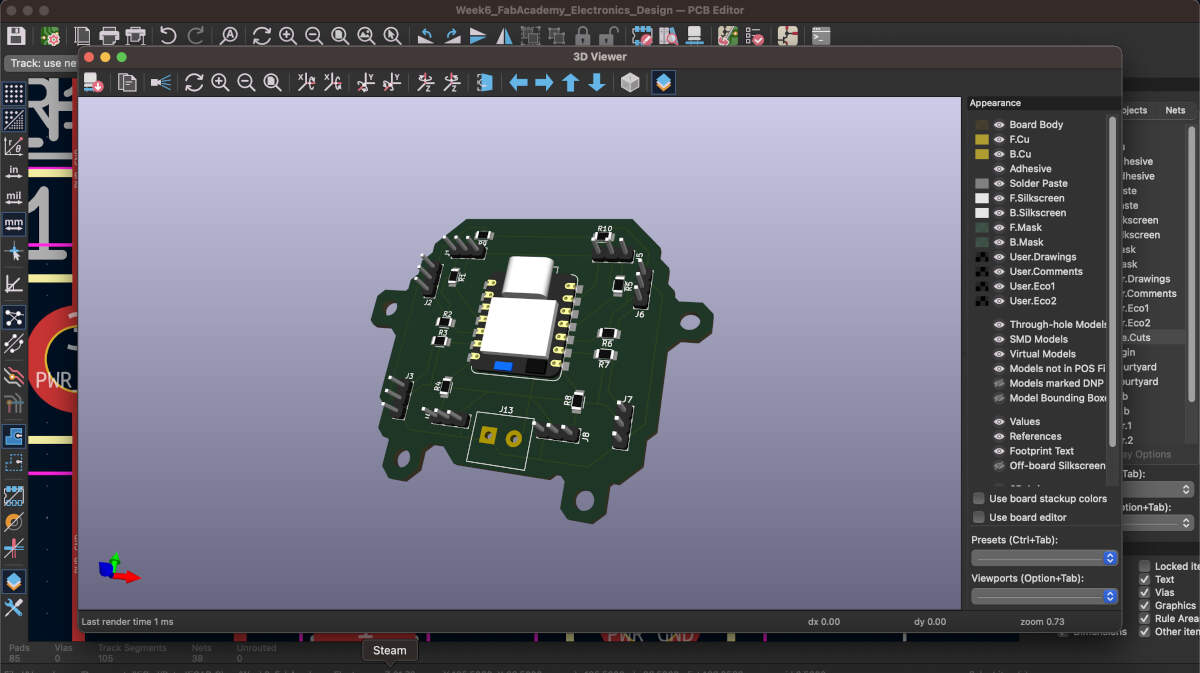
As per our individual assignment I have chosen an EDA tool to design my own development board. The EDA tool I chose was KiCAD. It is an open-source software that allows me to create circuit schematics and PCB's for milling, in addition to having a 3D visualizer built-in that lets me see the end result. I also used a FabAcademy library to supplement my design. This board is the first draft intended for use in my final project. It will incorporate eight 3-pin headers to go with the 8 servos needed for this project.
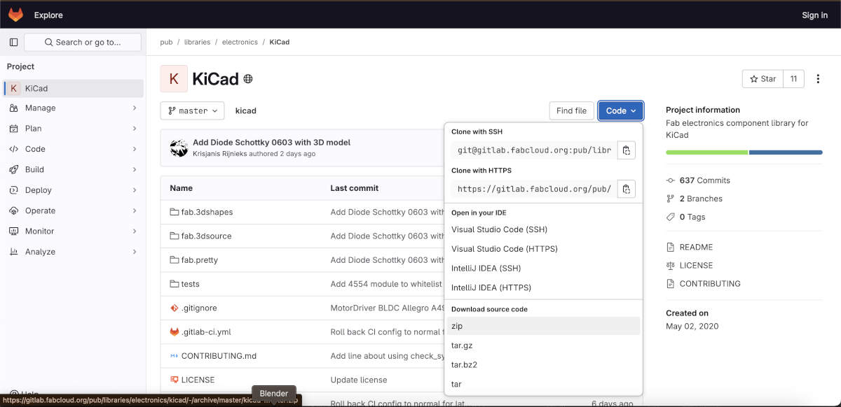
Slide 1: I installed the KiCAD FabAcademy footprint and symbol libraries to make use of in my design.
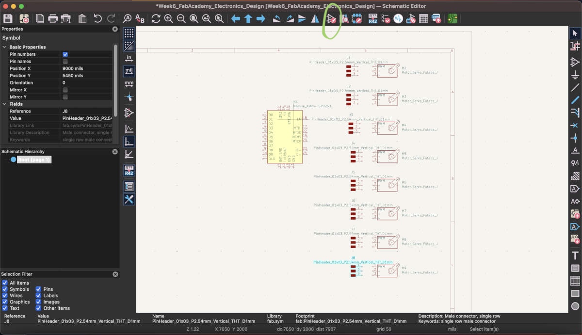
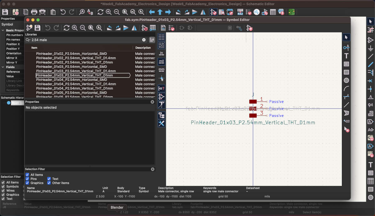
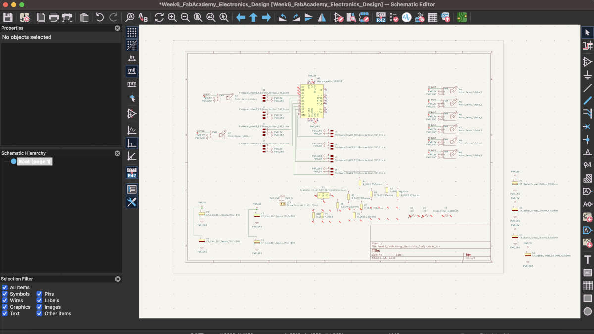
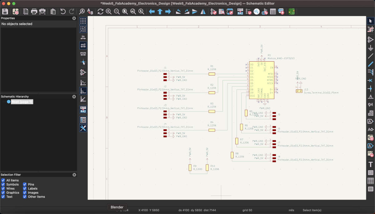
Slides 2-3: I had started adding in the components I believed were relevant to the project I had in mind using the Symbol Library. This allowed me to look up specific components that I would use within the circuit board.
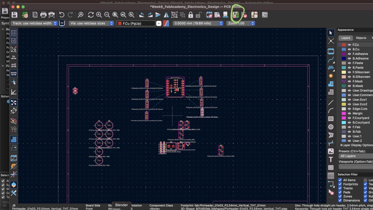
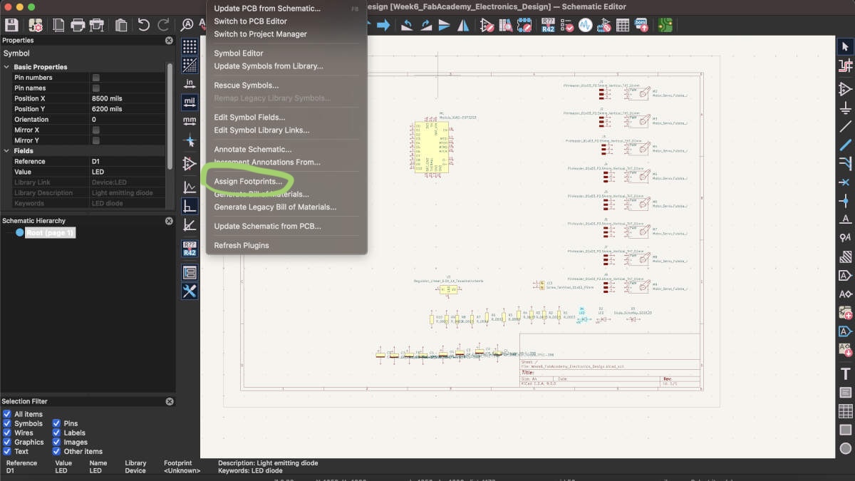
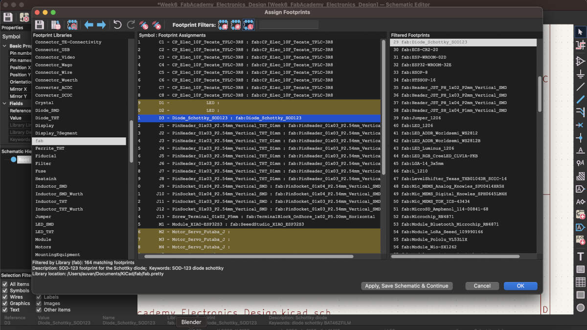
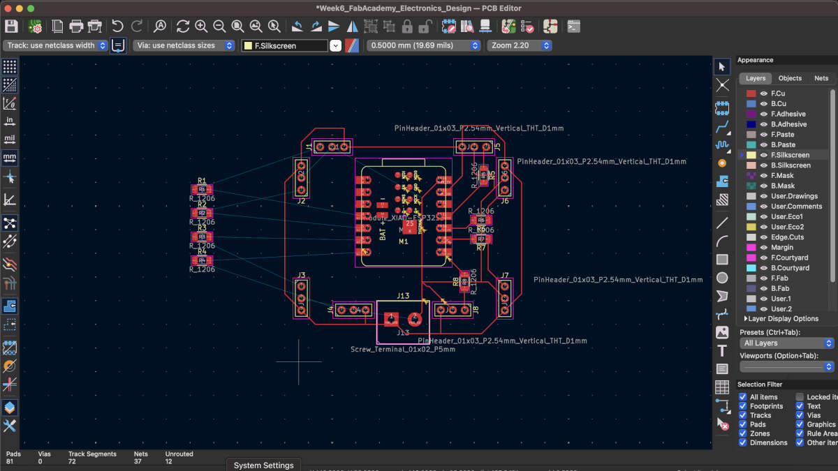
Slides 4-6: Once I was content with the components I was adding from the Symbol Library, I switched from the Schematic editor to the PCB editor. Here I was able to bring in the components I was linking together by pressing the button circled in green. This button allows me to update the PCB editor by bringing in all the components I had chosen in the Schematic editor. I slowly realized that not all components were there though. One of the errors I had consistently gotten when updating my PCB editor was something regarding footprints. Over time I realized that not all my components had an assigned footprint. Slide 5 demonstrates where I went to do this, and so I started assigning footprints to components I knew would be on the board. Servos remained unassigned due to them being external components.
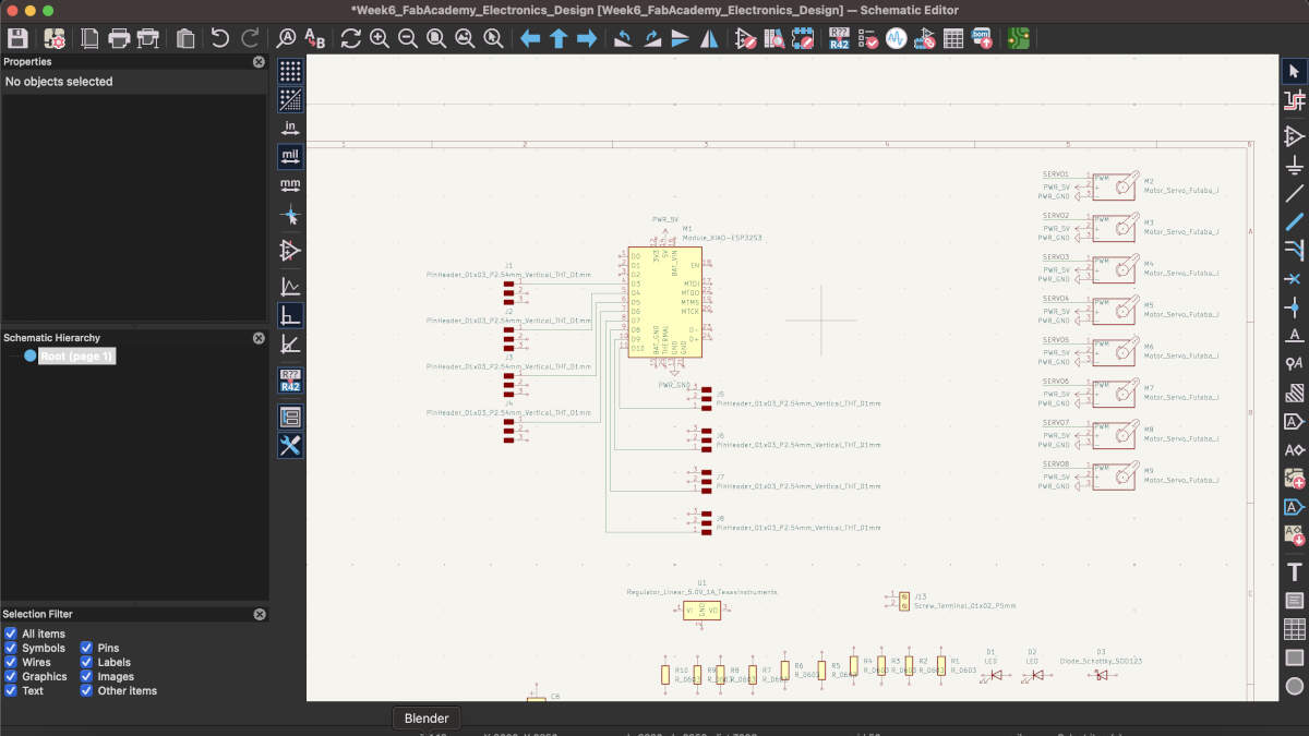
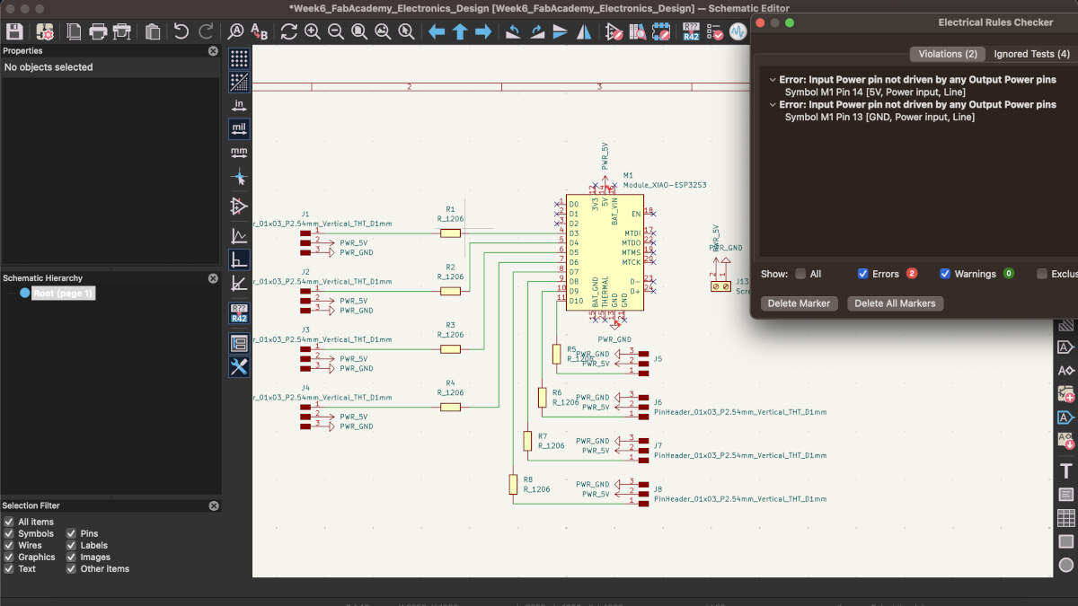
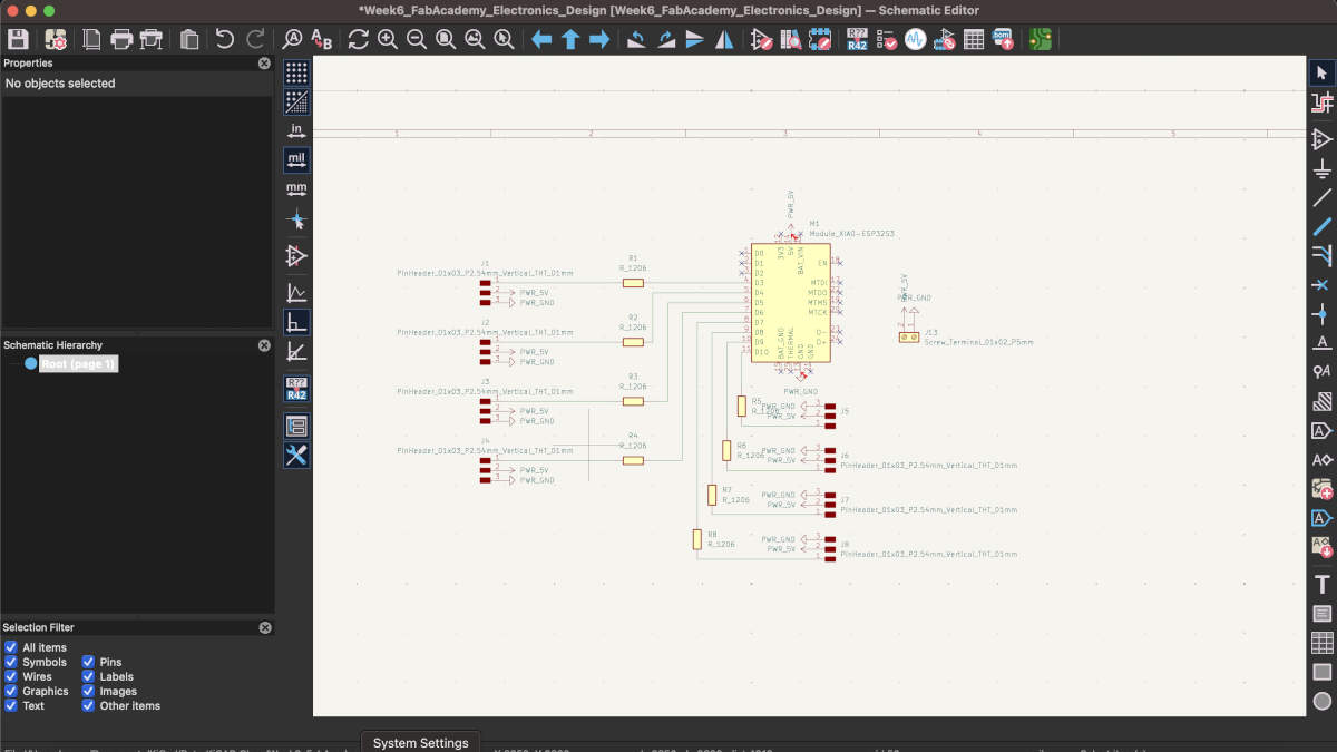
Slides 7-10: These next slides demonstrate the addition of new components and the beginning of making those components connect to one another. This is why the schematic editor is important as it allows to you organize your components and connections in a manner that is readable to the viewer rather than having the viewer analyze all the confusing snaking and winding paths on the PCB board itself. Slide 9 demonstrates errors I was receving when conducting an electrical check. Soon after I realized that this was occuring because I the 5V symbol doesn't function as an actual power pin, and to fix this I would have had to add an external power source like a battery. I excluded the battery source like I did the servos due to it being external even if relevant to the board. Slides 9-10 also demonstrate the vast simplification of my board. When speaking to an instructor I was told that many of the components I was trying to implement were not strictly necessary. They had specific uses that would be beneficial to the operation of the PCB but that I could do without them. I was really grateful to have been told this. Given my lack of familiarity with electronics I would not have been able to comfortably make a board while having so many components to take into consideration. This simplified everything for me as you can see in slide 10.
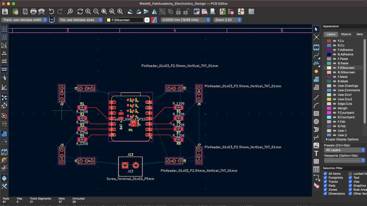
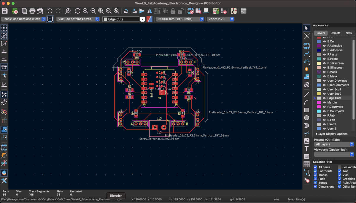
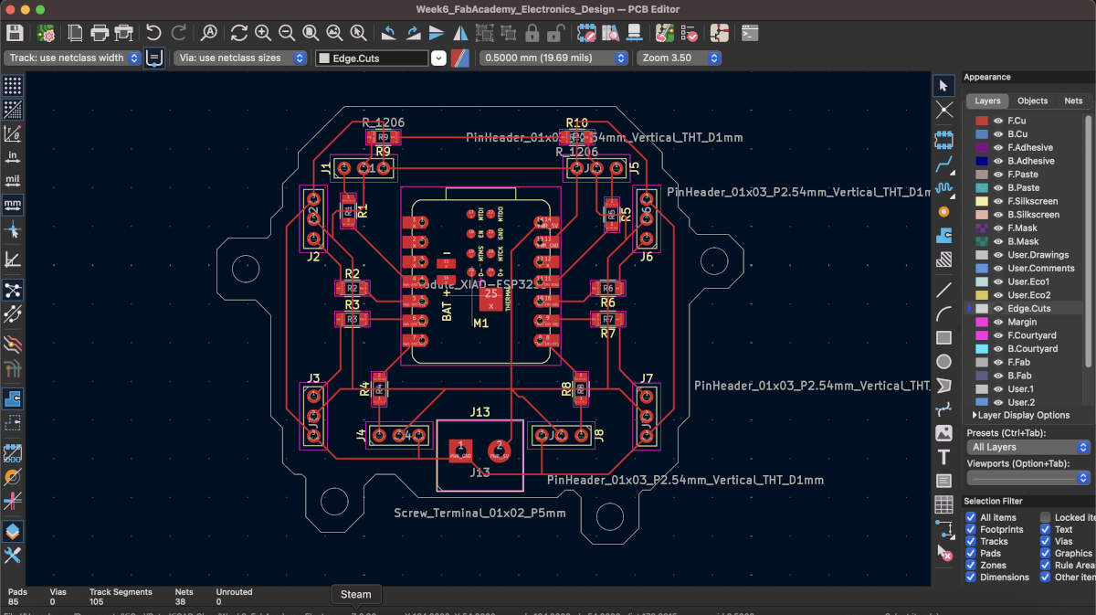
Slides 11-14: I went back to the PCB editor after streamlining the schematics. I started making connections based on the ones made in the Schematic editor. This is represented by the blue lines, which are not established connections yet. To properly establish them you have to make use of the red lines seen in the images so that the pins and other components on the board properly communicate with each other. These red lines will later but cut into the board to physically do the same. The connections began getting more convoluted so I added in two more 0 ohm resistors in Slide 13. The purpose of these were to close the PWR_5V loop going around the board by bridging over some of the PWR_GND lines. I was able to successfully do this and started drawing out the perimeter outline of my board. These white lines represented the PCB that was going to be cut out mimicking whatever shape is made with them.
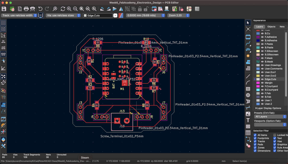
Slides 15-17: I finalized all connections and the outline but realized that in the future I would need to safely secure the board onto my final project so I created protusions with holes in them that would allow the board to sit on threaded heat set inserts and have screws secure it in place.
To start off with the group assignment we decided to stick with the Quentorres board we had used during Week 4 for Embedded Programming. We retained the hello.button-blink code provided to us by FabAcademy in the microcontroller and used its code as a part of our tests.
Slide 1: We began by using the multimeter. Incidentally, we discovered that we could short-circuit our board by inadvertently connecting two points or two pins in this case that should not be connected. In short-circuiting the board we caused the board to shut down. Breaking this temporary connection causes the board to turn on again.
Slide 2: Moving forward with the multimeter, we found out that we get two voltage readings. One for when the circuit board has the LED on with a reading of 4.5, and when the button is pressed, which shuts off the LED, the voltage goes down to 1.729 indicating less power usage.
Slide 3: The oscilloscope was used in the second test. The two green arrows on the screen indicate its base level, the line is at the same level. When the oscilloscope is used to make contact with a part of the board, you can see the line sink downwards. This is representive of the voltage being used to in the board. The LED in the board is always powered on unless you press down on the button. When the button is pressed it shuts off the LED, less voltage is being used and this is seen in the video when the line slightly moves upwards. Ending contact springs the line back up to its original position. These results mirror the test with the multimeter.
Copyright 2025 Augusto Vanegas - Creative Commons Attribution Non Commercial Source code hosted at gitlab.fabcloud.org