


Individual Assignment:
- Design and document the system integration for your final project.
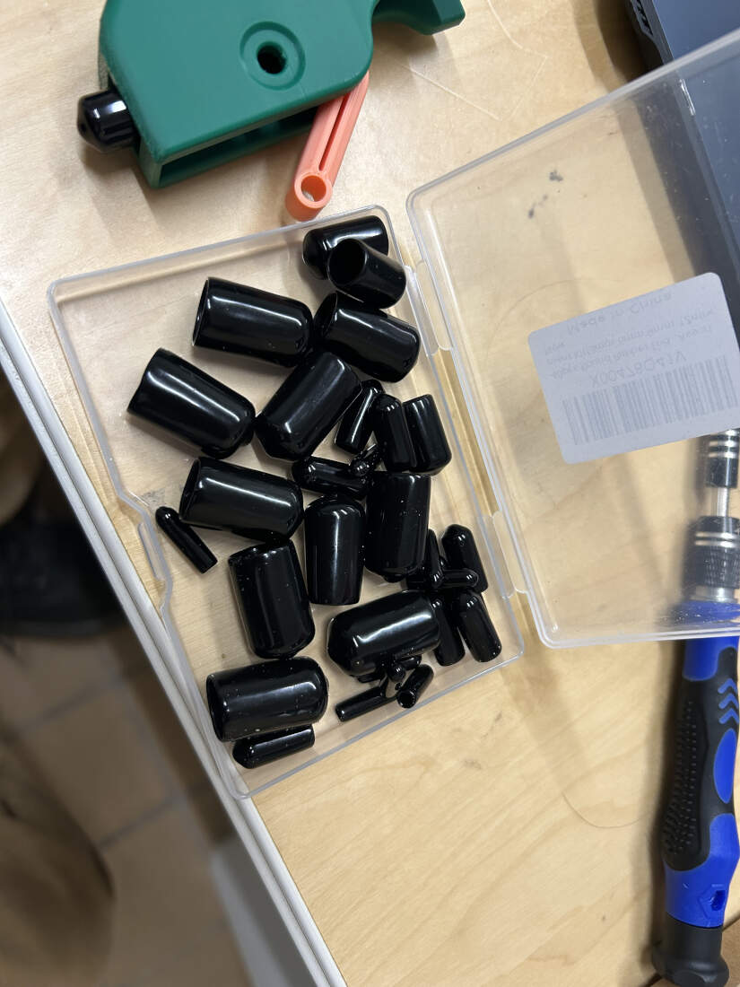
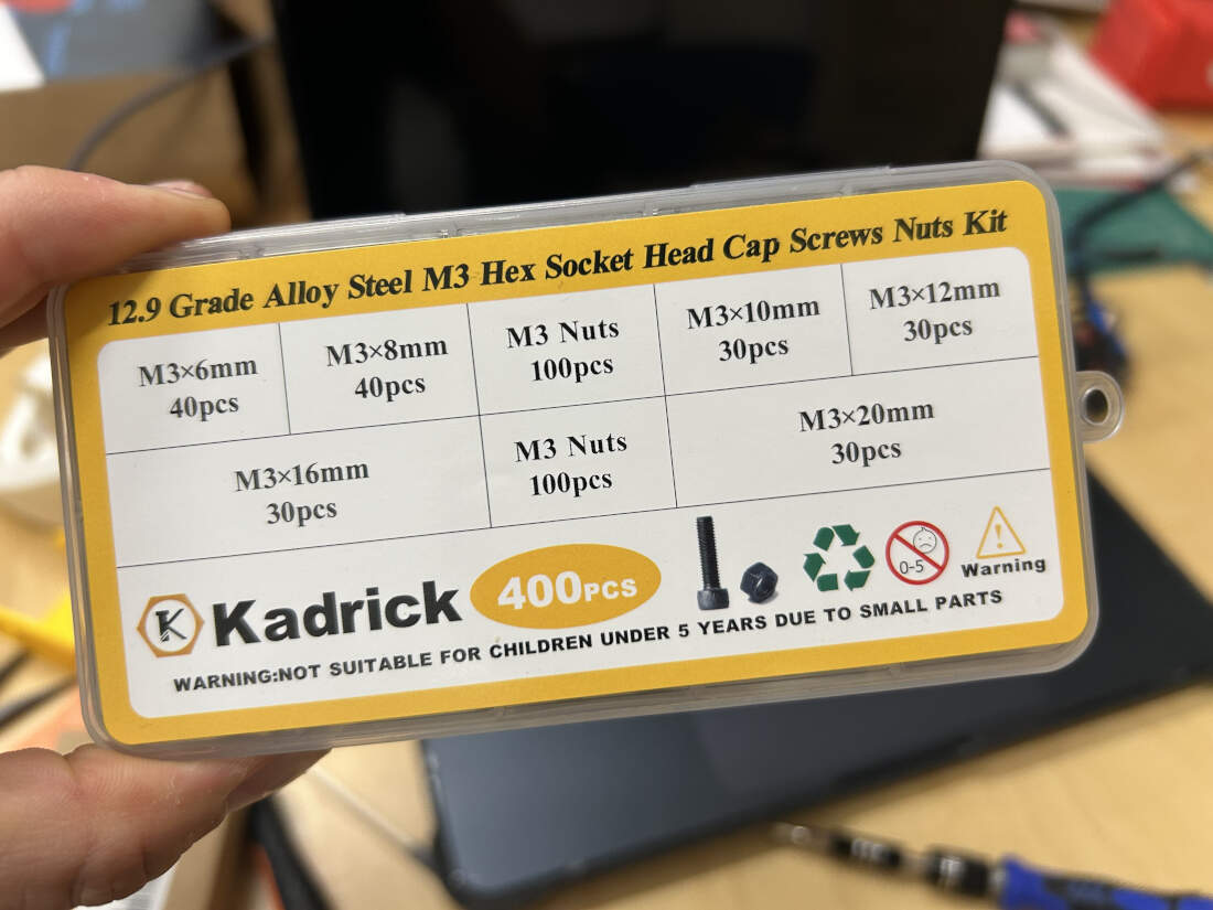
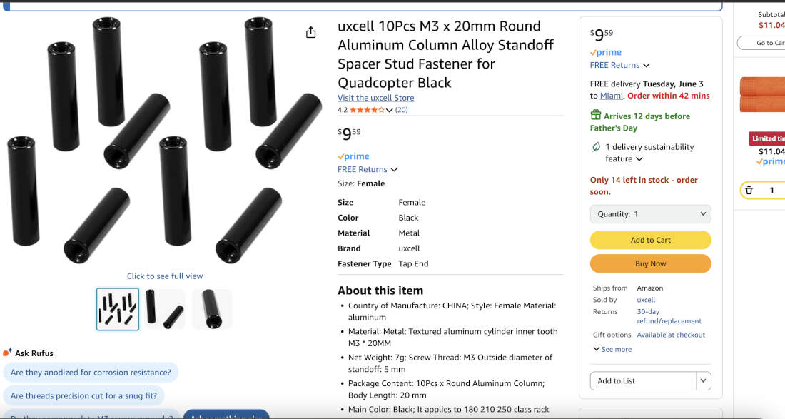
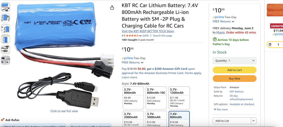
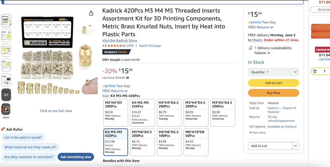
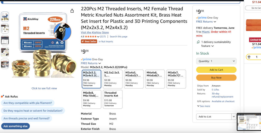
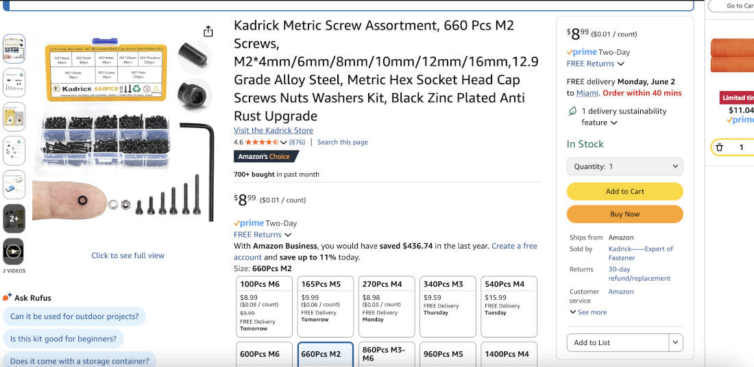
Some of the purchased bits needed to finalize my project. You'll see them being used throughout. The items are -
- Rubber End Caps for the Legs
- M3 Hex Bolts
- M3 x 20mm Standoffs for Leg Actuation/Movement
- 7.4v 800mAh Lithium Battery for Power
- M3 Heat Set Inserts
- M2 Heat Set Inserts
- M2 Screws
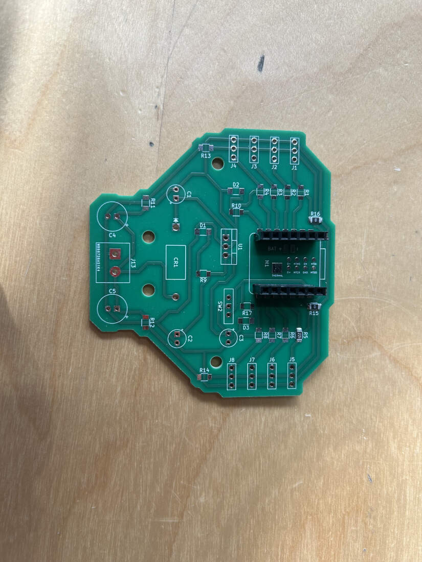
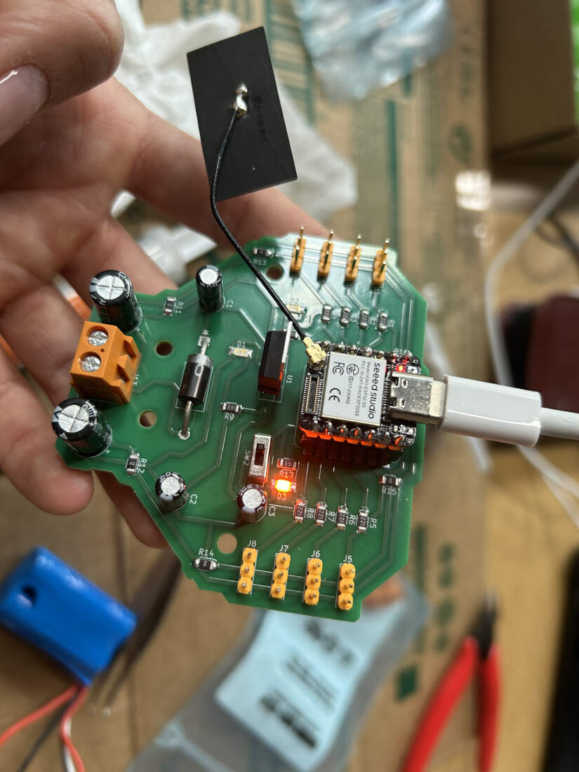
My board design had been finalized and tested in previous weeks. I had put in an order through PCBWay to obtain "final" versions of my design. I soldered all necessary electronics components to have it functioning like the milled version.
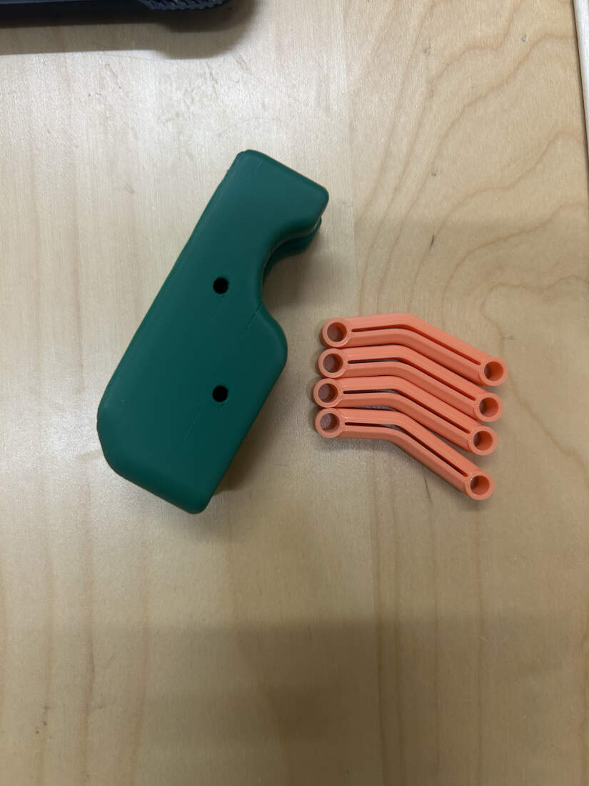
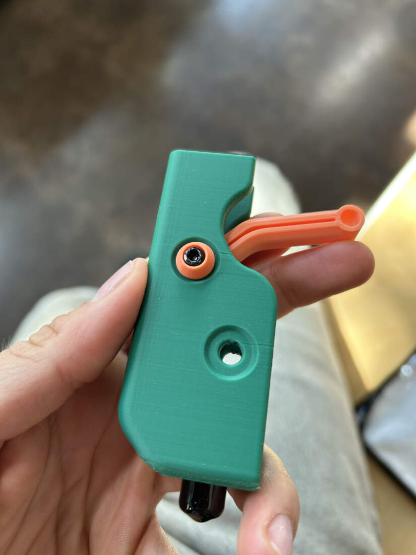
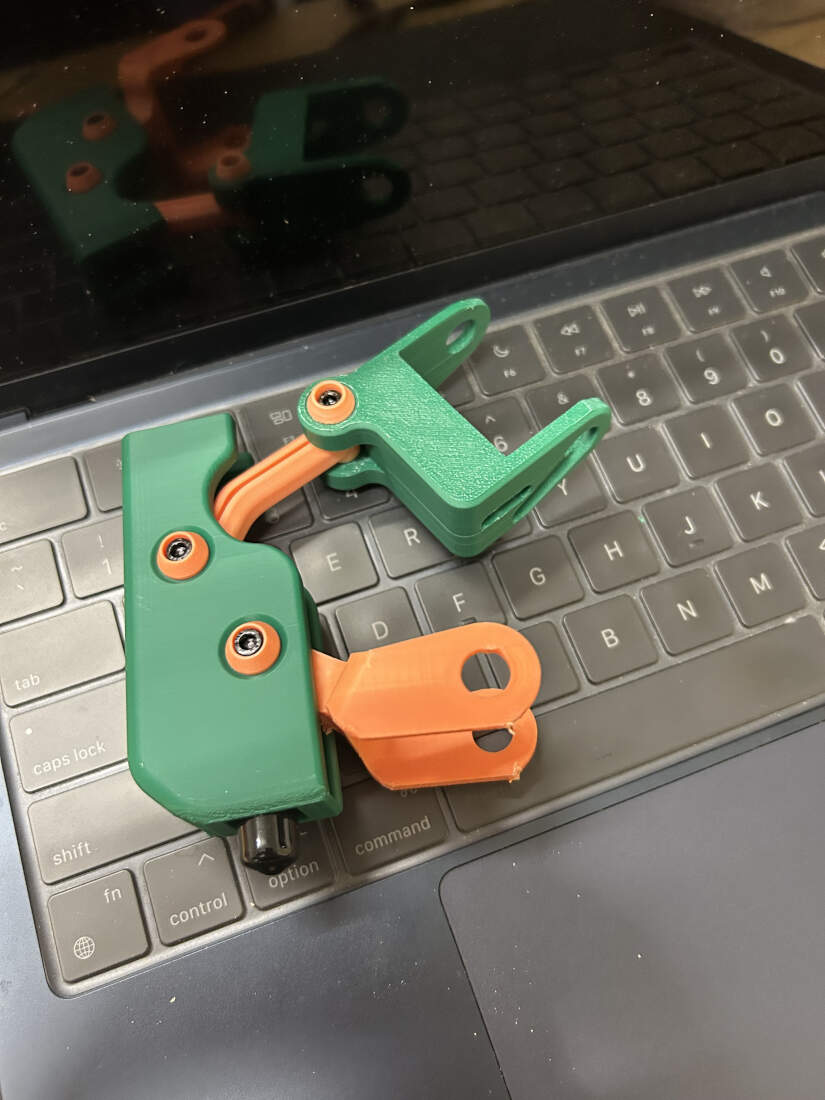
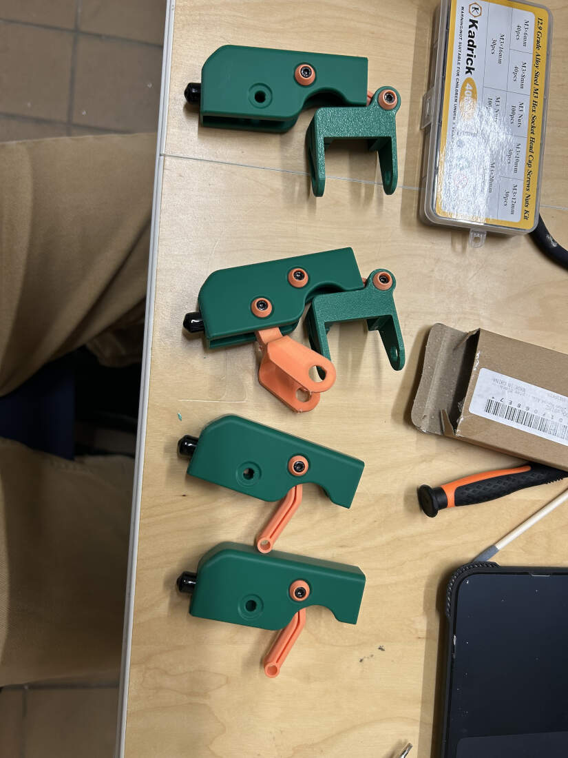
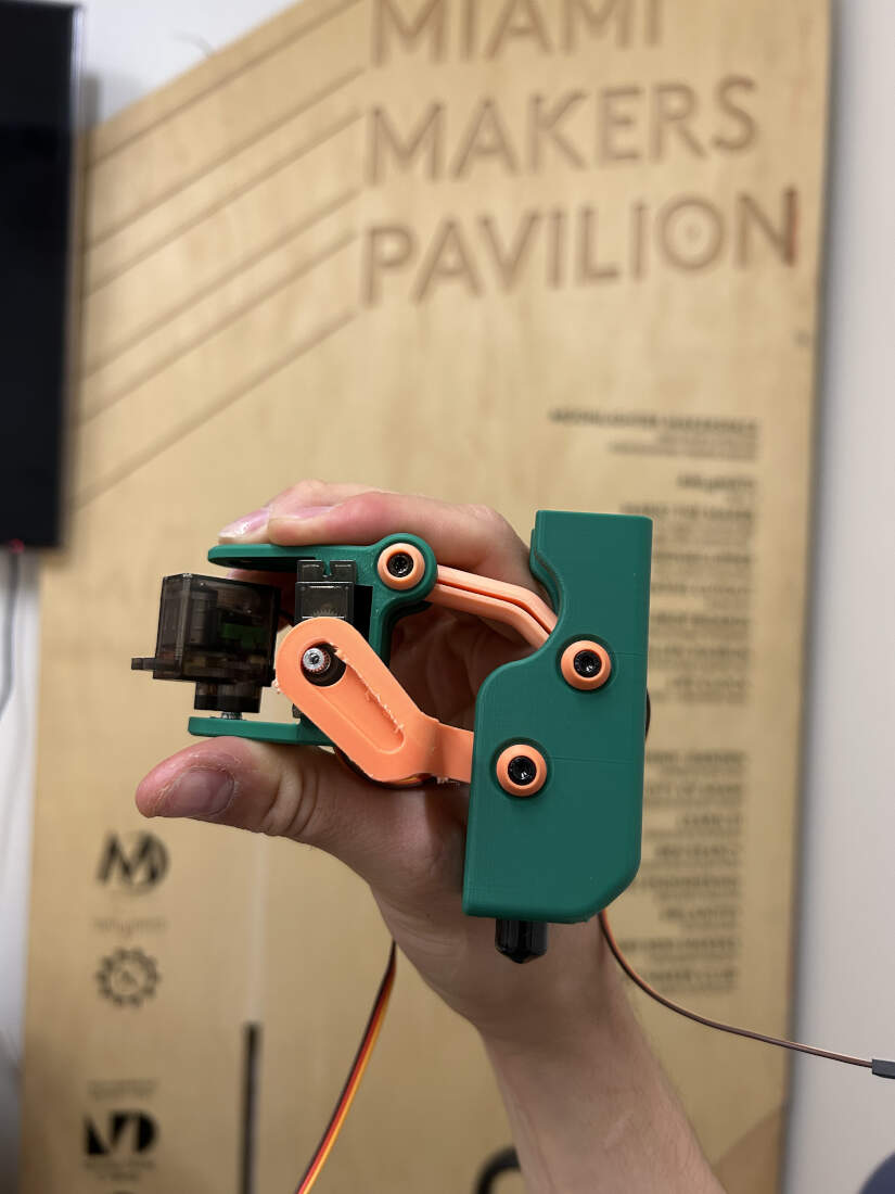
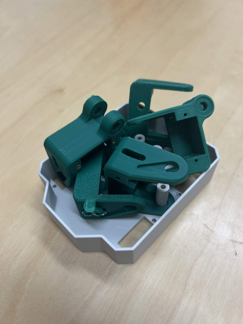
Legs started off really simple but were graudally developed to account for the hardware that was being implemented. Recesses were boolean differenced into the model to create a nice detail/semi-flush area to allow for a tapering bolt cover. This accomplishes a few things by covering the majority of the bolt, any possible standoff exposure, and further hiding any print artifacts created when printing overhanging curves. Rubber end caps are press-fit below. Standoffs and bolts further implemented to hold other parts of the leg. Some of these parts, seen in slide 5, require further development (orange bit at bottom, and rightmost green bit). They require resizing to fit the plastic arm bits that attach to the servos as seen in slide 7. Last slide shows various different versions that I went through to get the swiveling portion of the leg correct as needed by the rest of the robot.
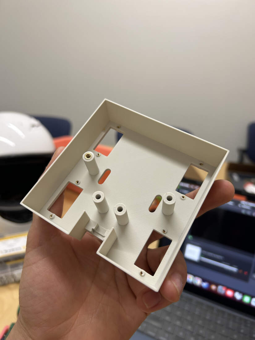
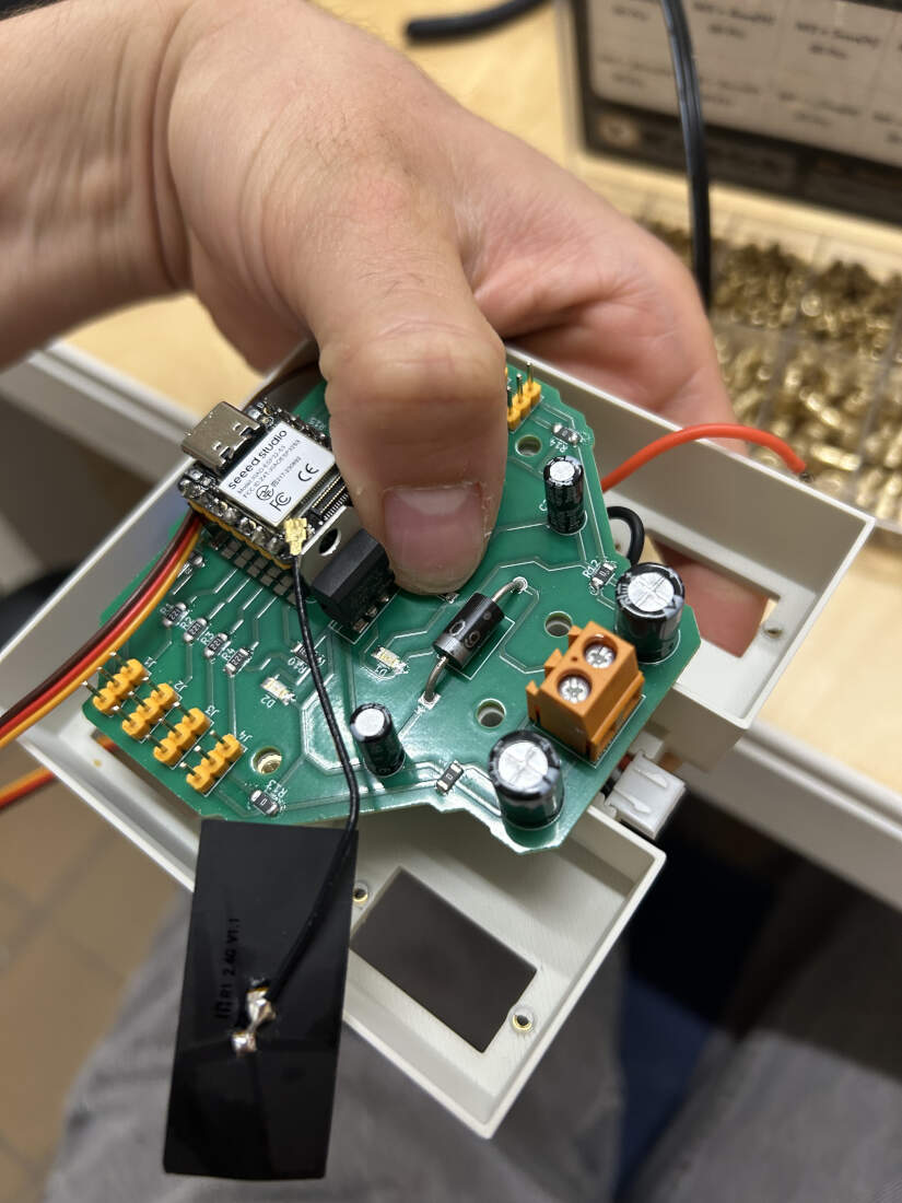
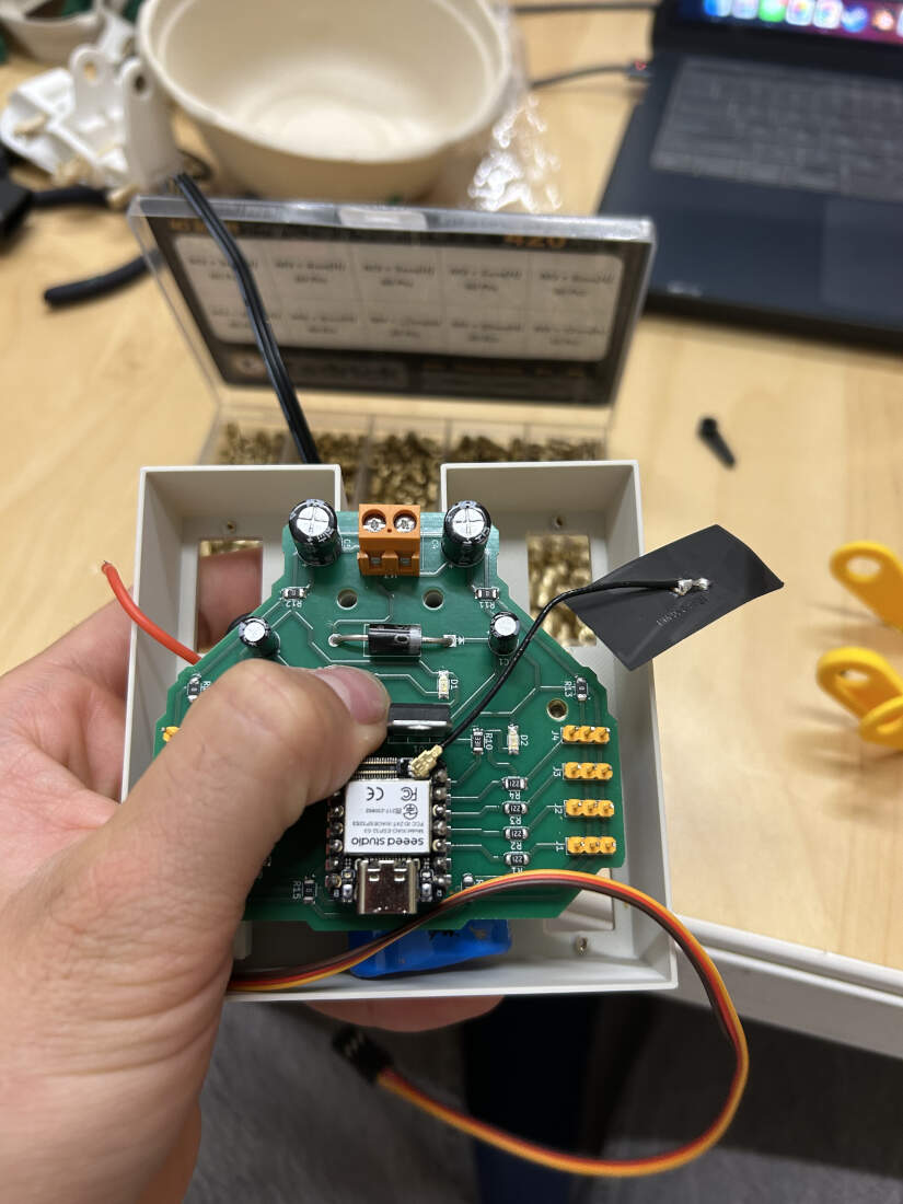
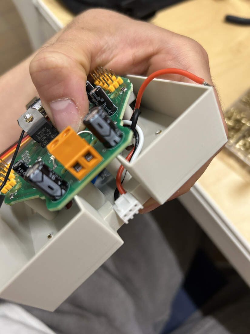
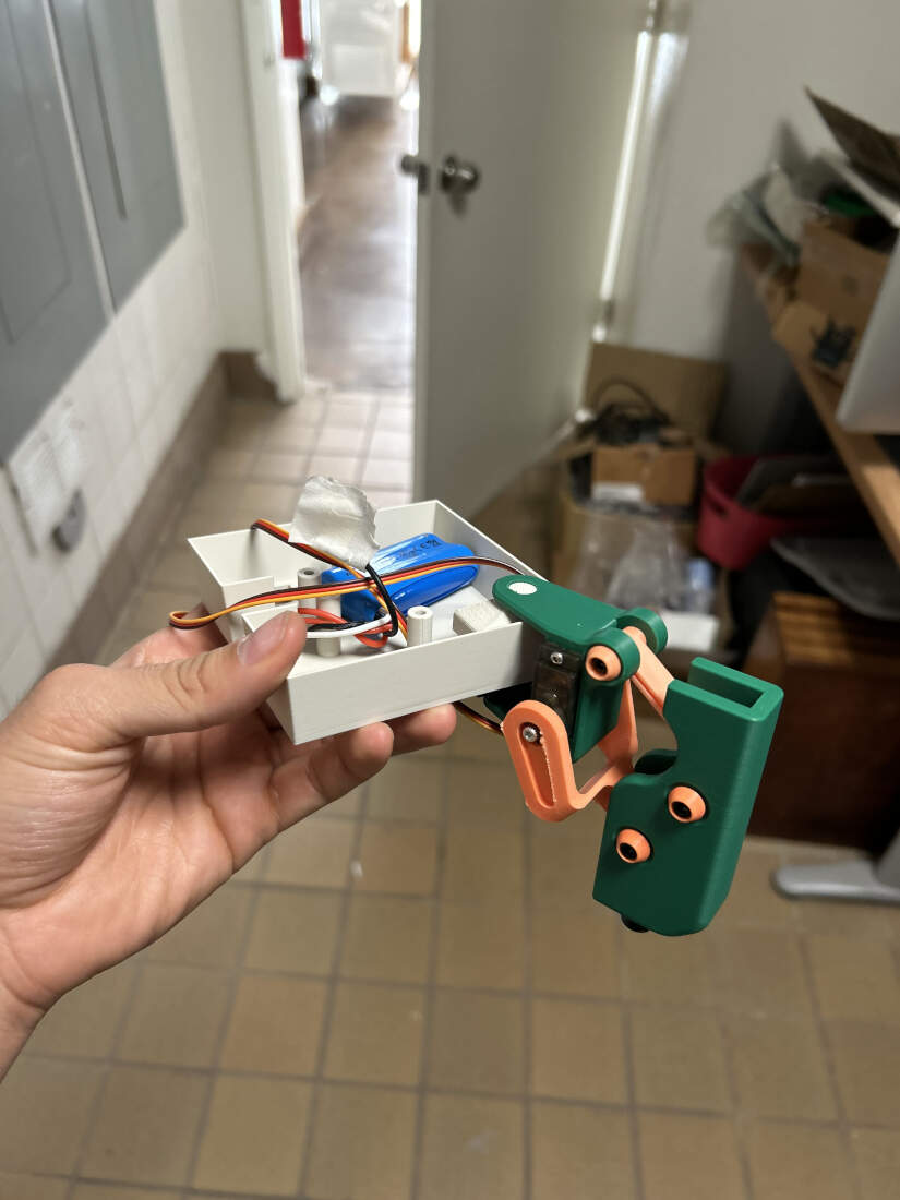
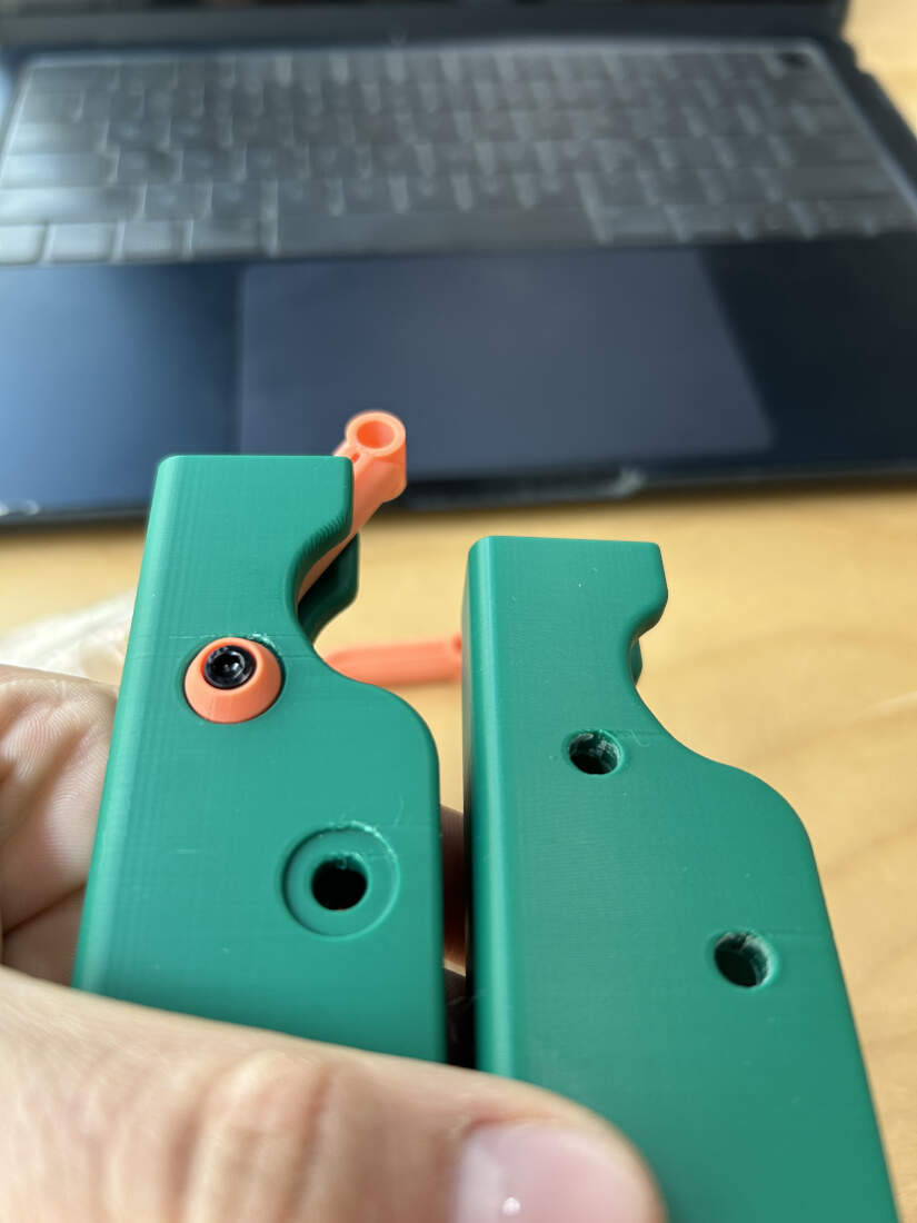
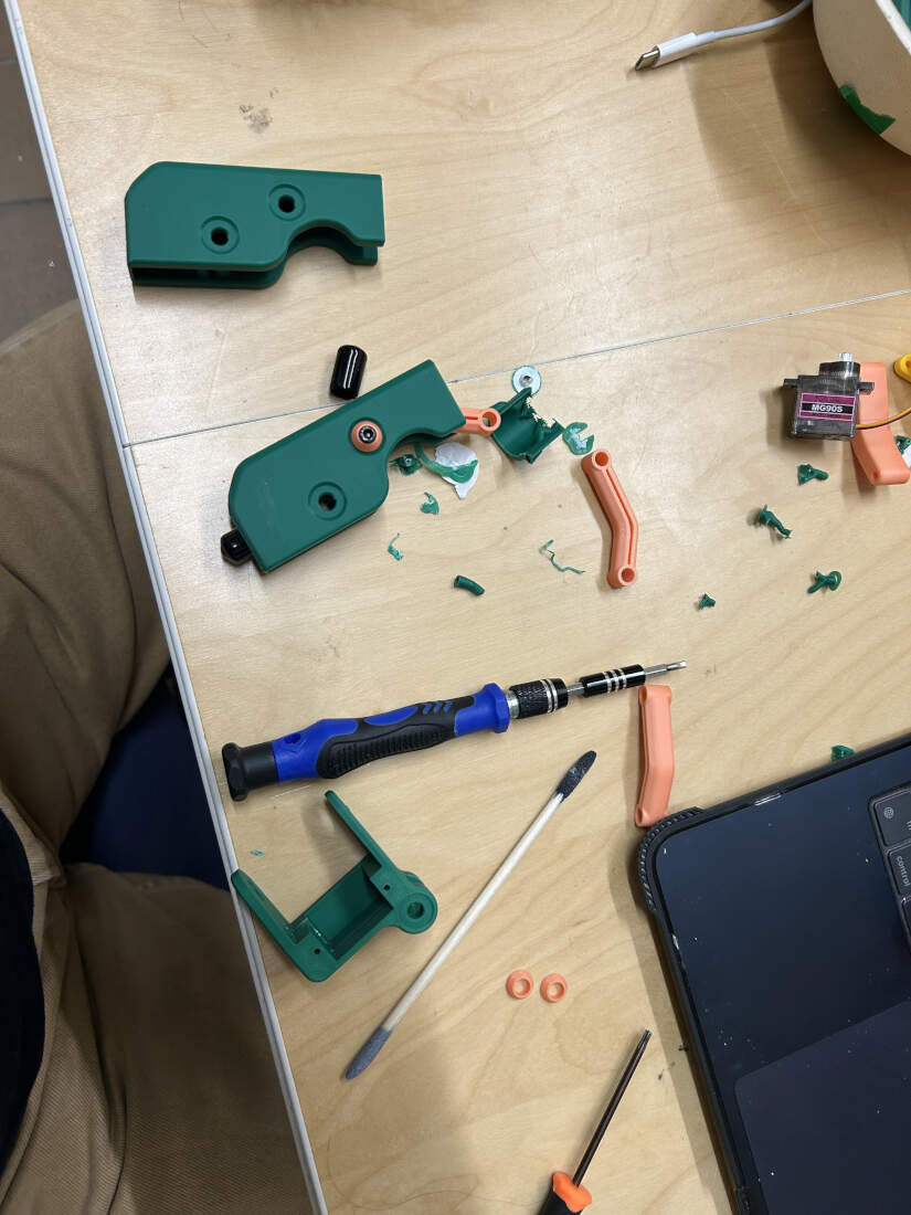
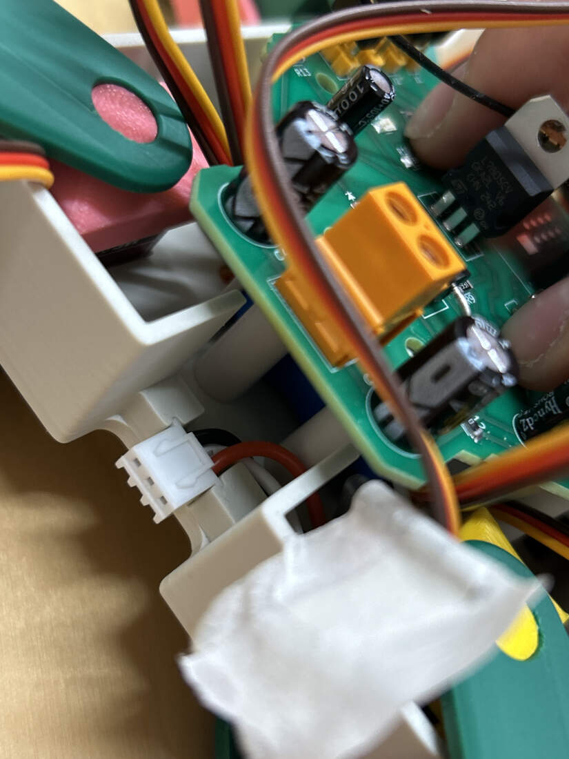
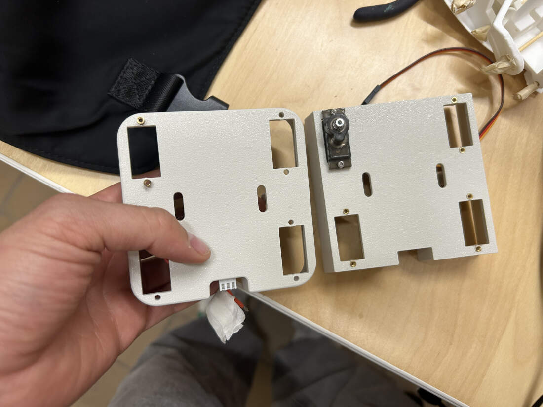
First version of the chassis modeled. Heat set inserts tested. Support standoffs for PCB require wider holes. Inserts for servos are fine as they are. I tested the placement of the PCB. While it aligned perfecetly fine with the printed standoffs, you can see that the way the first chassis was modeled would cut off access to the screw terminal on the PCB. This is something to fix. Thankfully the area I modeled to hold the battery's charging cable was good enough to hold the male cable head in place. This needed additional work though as I did not want a gaping hole over the "charging cable holder" in the final version. The chassis was a good WIP though. I was able to attach the leg onto the chassis. The rectilinear chassis created issues with the movement of the leg because its sharp corner would scratch a portion of the leg when it swiveled creating friction. This would be fixed. If looking closely at the last slide, you can see the green of the leg surrounding a bone white circle. This bone white circle is a part of a "ball and socket joint" I made as a cap to place over the servos. The ball is the cap, and the socket is the circular hole in that portion of the leg. I suppose that portion of the leg can be seen as one of four pelvises. Progress made on the joints will be seen below.
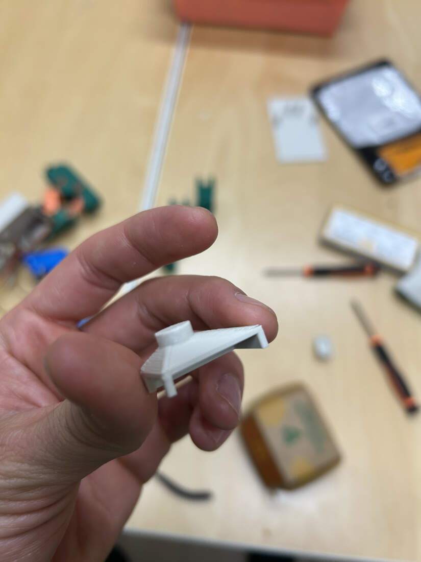
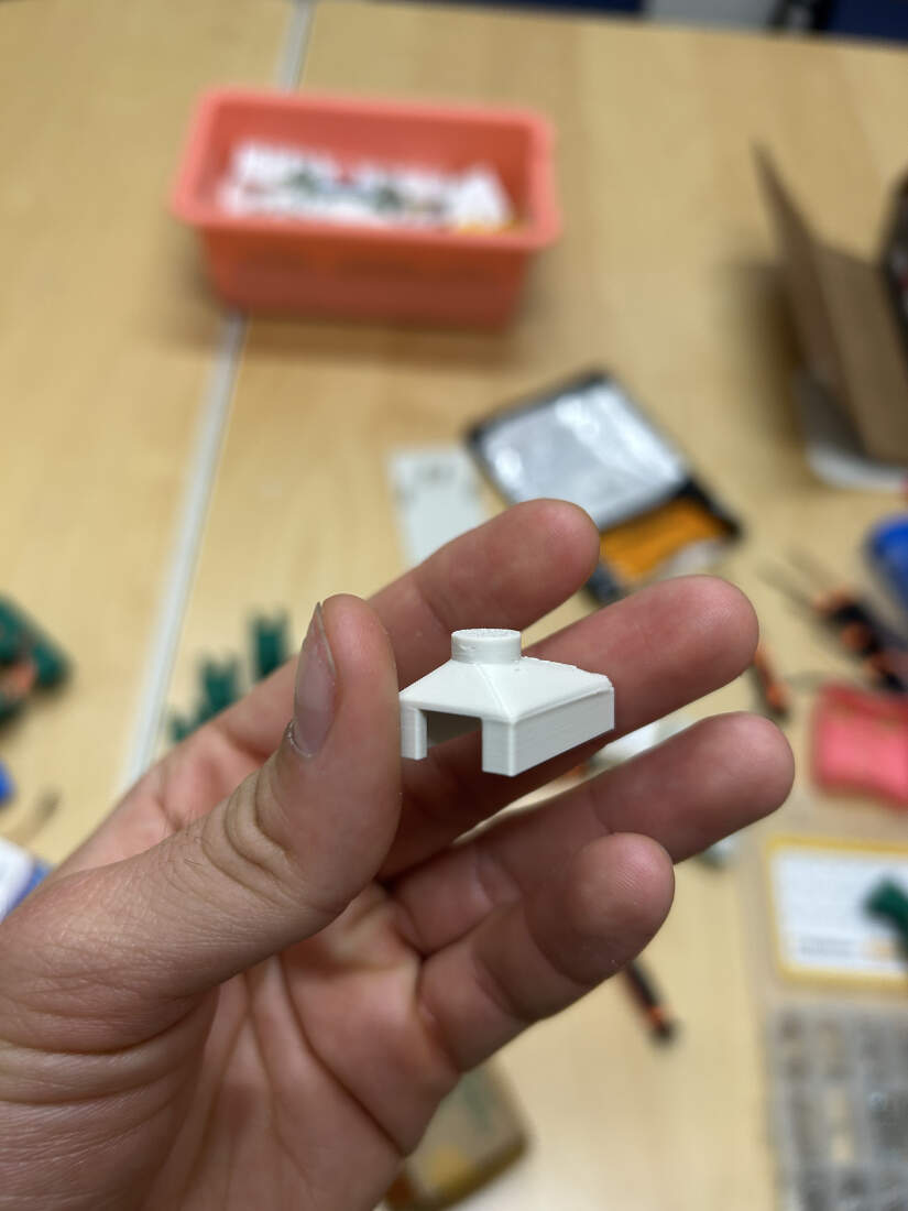
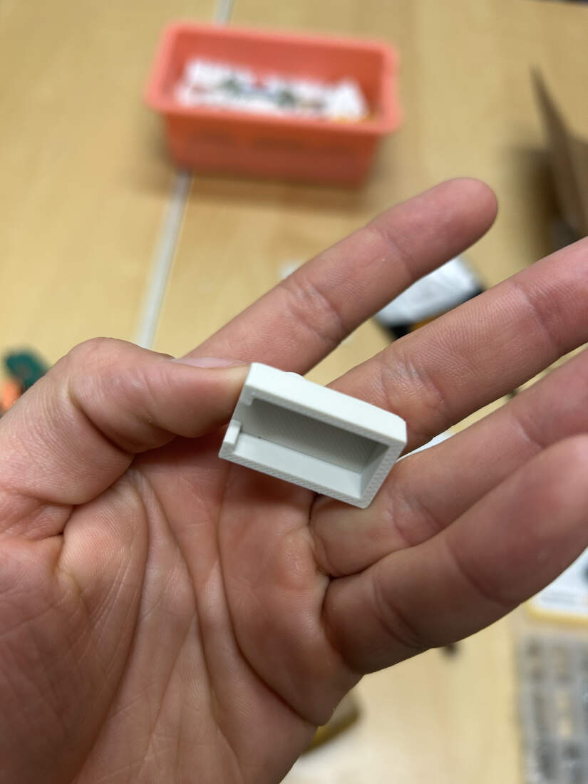
The first version did not fully encompass the servo. One of the sides was open. This would cause it to slip off the servos. To solve this issue the walls were extruded to be longer and they encompassed all 4 sides now. The tolerance was so good it could be press fit so the part would stay firmly in place over the servos.
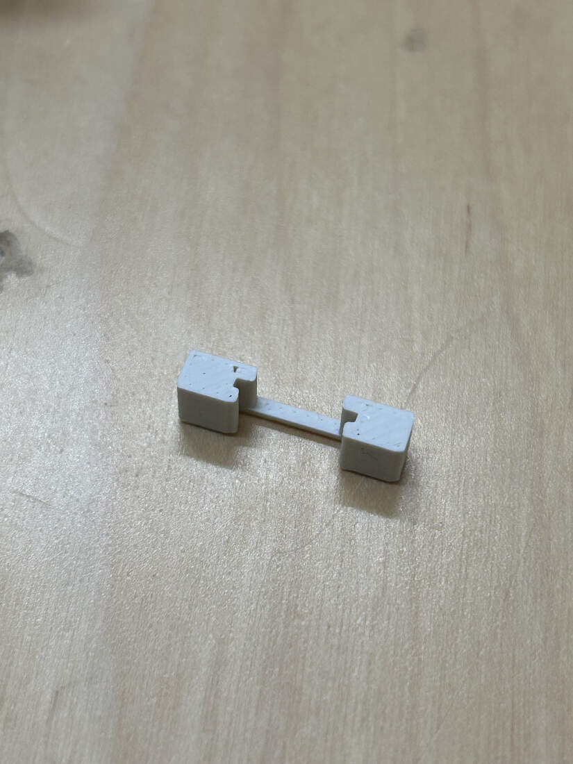
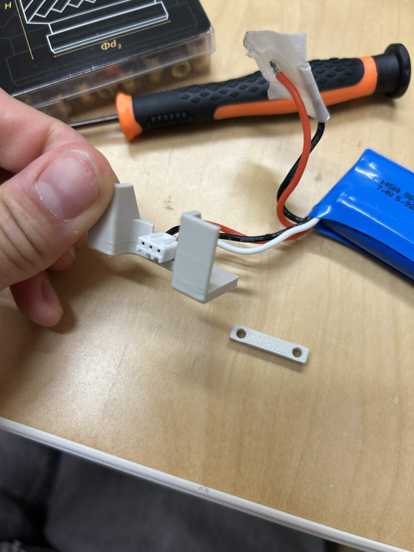
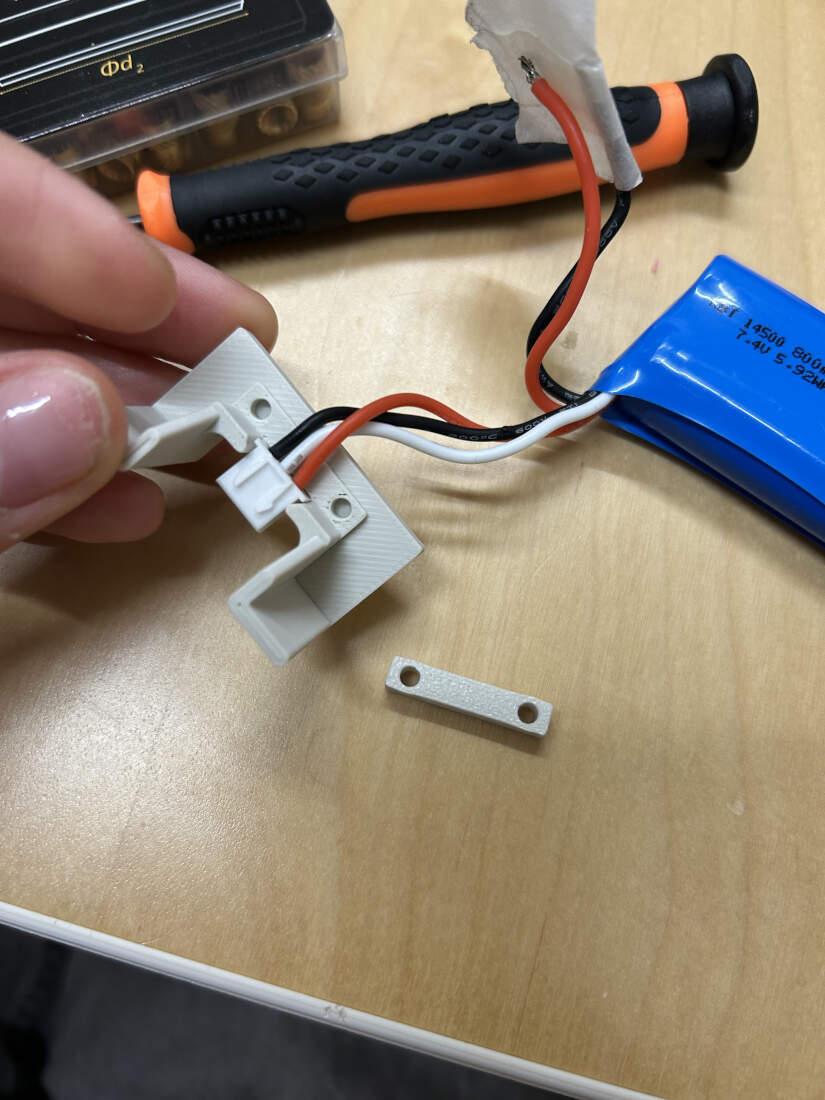
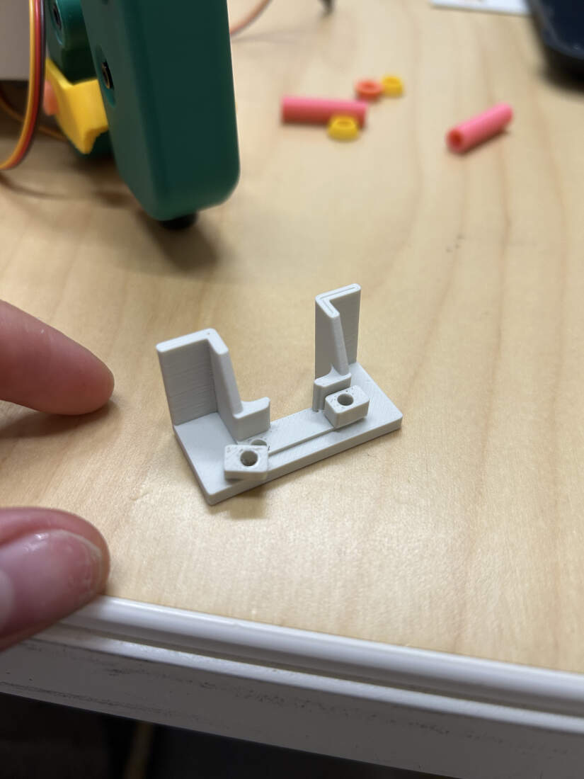
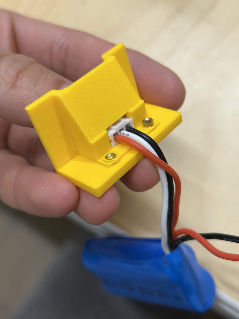
The first version of the holder started of as a small separate piece to test tolerances. It thankfully worked on the first try as I used calipers for measurement. The second version was put in the first chassis. To solve the PCB cable clearance issues, this area was further developed while also trying to match the rest of the design. This portion of the model was also cut or trimmed out to save on time and increase my focus on just that area. I decided to create two other areas to include heat set inserts in and printed a long rectangular piece to screw in place allowing me to hold the cables male head in place. I forgot the cable was in the way of setting the entire rectangle down so I cut it down into two separate blocks. After seeing that that worked I then included the overhanging wall over the cables head to give off an enclosed appearance. Those inserts did not fully fit but thats because I did not extrude the surface high enough so I did that for the final chassis model.
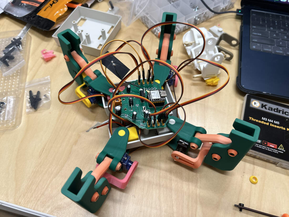
New chassis with rounded corners being tested. Swivel movement of the legs is now uninterrupted. Various ball and socket joints printed and being used for the legs. All four legs fit on the robot just fine. PCB can mount just fine, still has the clearance issue but that is being fixed soon. Cap to hide electronics being developed soon.
Copyright 2025 Augusto Vanegas - Creative Commons Attribution Non Commercial Source code hosted at gitlab.fabcloud.org