


Individual Assignment:
- Add an output device to a microcontroller board you've designed, and program it to do something
Group Assignment:
- Measure the power consumption of an output device.
When messing around with inputs last week I had also incorporated an output, a servo motor in one of my tests. I wanted to further explore the use of servos this week given that I planned to build a tetrapod spider bot with two degrees of freedom(2DOF) as my final project. My original board did not have any protection so over the past week I had been redesigning my original board so that I could comfortably use up to 8 servos without having to worry about noise interference, component damage from excessive current, or voltage spikes. I have slowly been building up an understanding of electronic components but I still did not have the confidence to say that something I put together would be sufficient for a project I had in mind so I did some research and looked at other peoples projects and I came across this link -
https://www.instructables.com/4-Legged-Spider-Robot-With-3D-Printed-Parts-8-Serv/
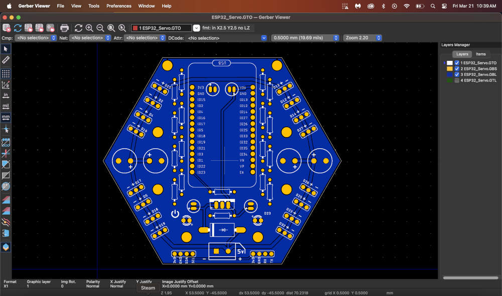
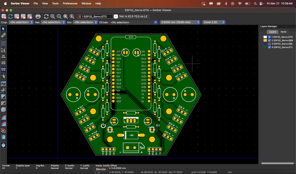
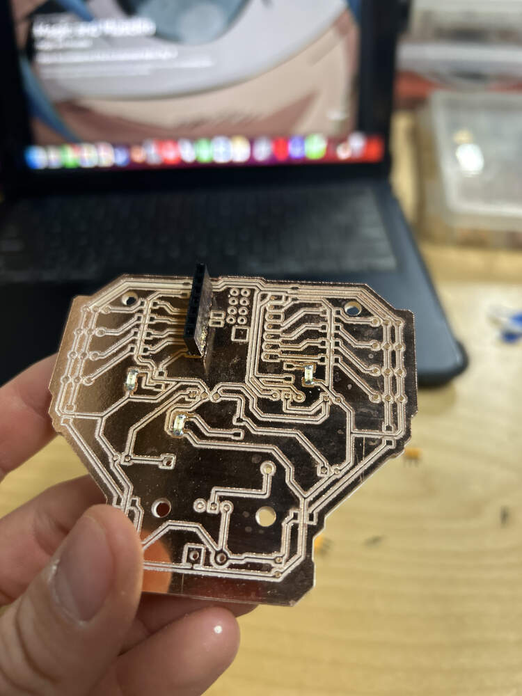
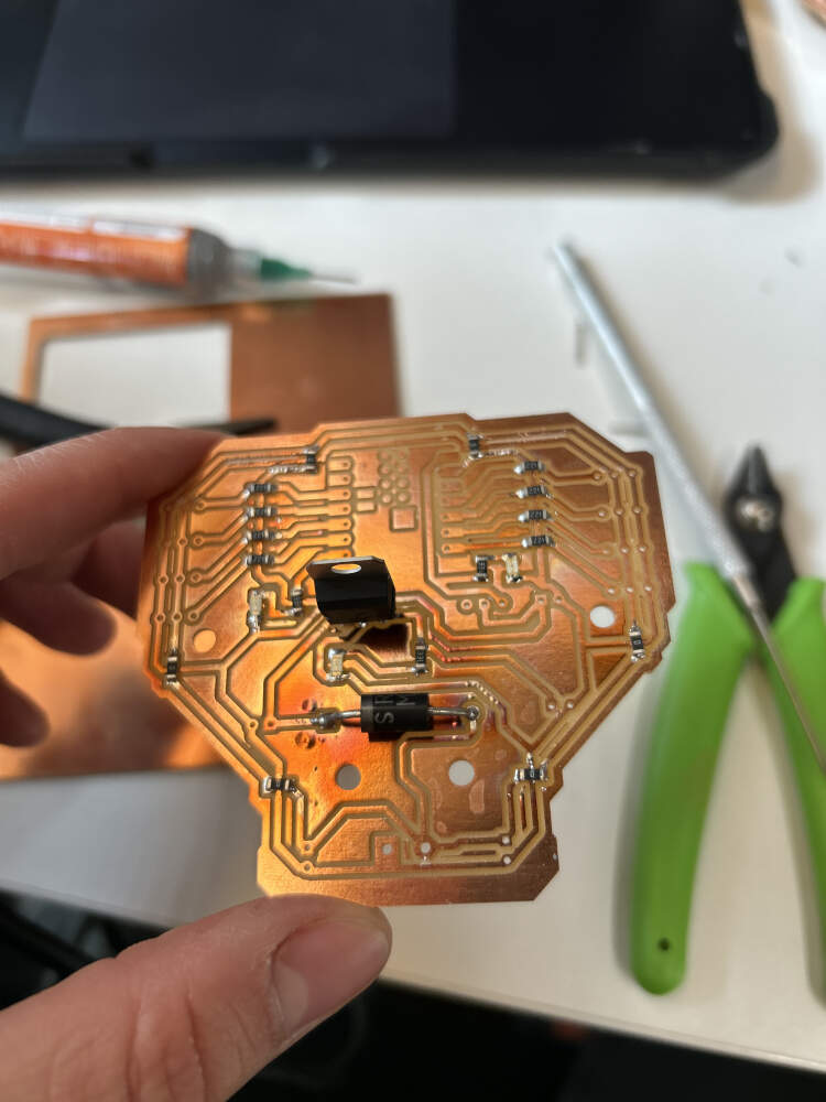
The Instructables tutorial features a four legged spider robot like the one I want to build for myself, but more importantly, they designed their own board. Using their board as a basis I then took many of the components they used and added them to mine such as the resistors (to prevent the LEDs from getting burnt out with excess current and the servos from receiving noise interference), 100uf and 470uf capacitors (to act as a buffer in the case of current peaks and voltage drops and as a filter to prevent electrical noise from reaching the servos), a 5V regulator(this converts the 7.4V external battery source into 5V as it reaches the microcontroller to prevent it from getting overloaded and burnt out), the SB560 diode (has electricity flow one way to the microcontroller), and the LED's (show electricity passing in certain areas, I added a third to experiment with potential statuses of my board).
The Gerber files for this tutorial were available for download and I then used my Mac's Gerbview to inspect the layers of the board to gain a proper understanding of circuit paths. The images are located above.
You can see the original board I was referring to by following this link here - https://fabacademy.org/2025/labs/moonlighter/students/augusto-vanegas/assignments/wk6.html
Even though I originally did not want to design another board, I am glad I did because it has only further reinforced many of the things I have been learning and giving me a greater understanding of the components I am working with.
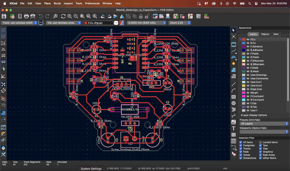
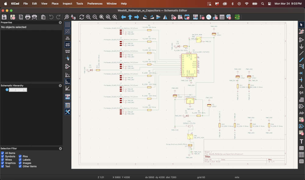
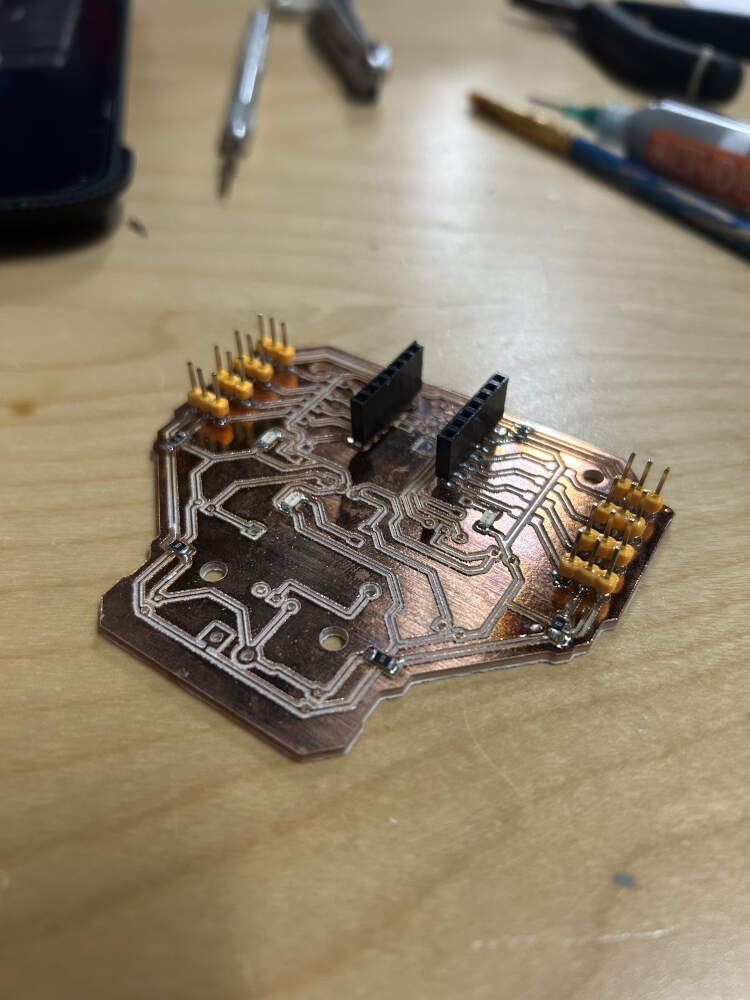
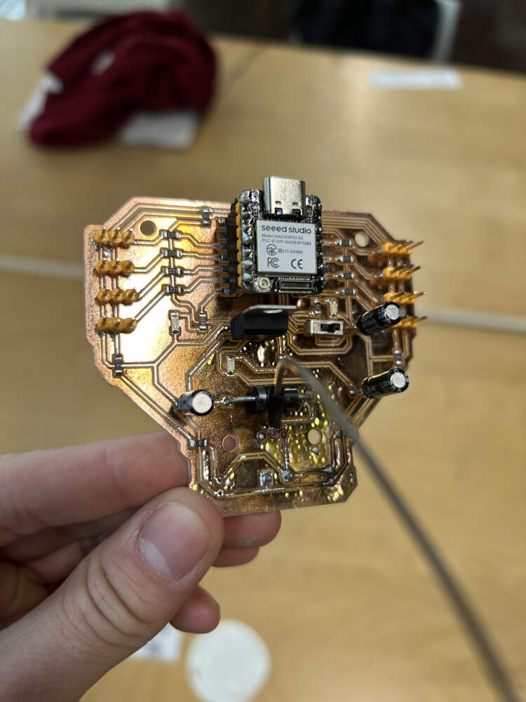
The new board featured many of the components I had already discussed above, or had used in my previous boards, but a new component that I added to the design was the slide switch. At this point in time I added two onto the board. One was located right after the screw terminal allowing me to shut off power from the start of that circuit, and the second was located right before the microcontroller. The second one allowed me to prevent power from going to the controller in case it was connected to my computer, and the board connected to the battery to prevent any potential burnouts. This second switch was wired in a way that allowed power to flow from the battery to the microcontroller, but in the event that I did not have the battery wired into the board, I could flip the second switch and reroute power from the microcontroller (if powered) to the rest of the board for small scale testing with one or two servos.
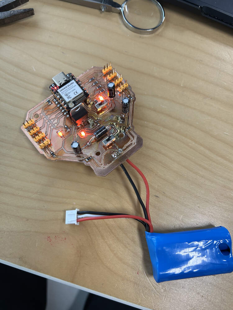
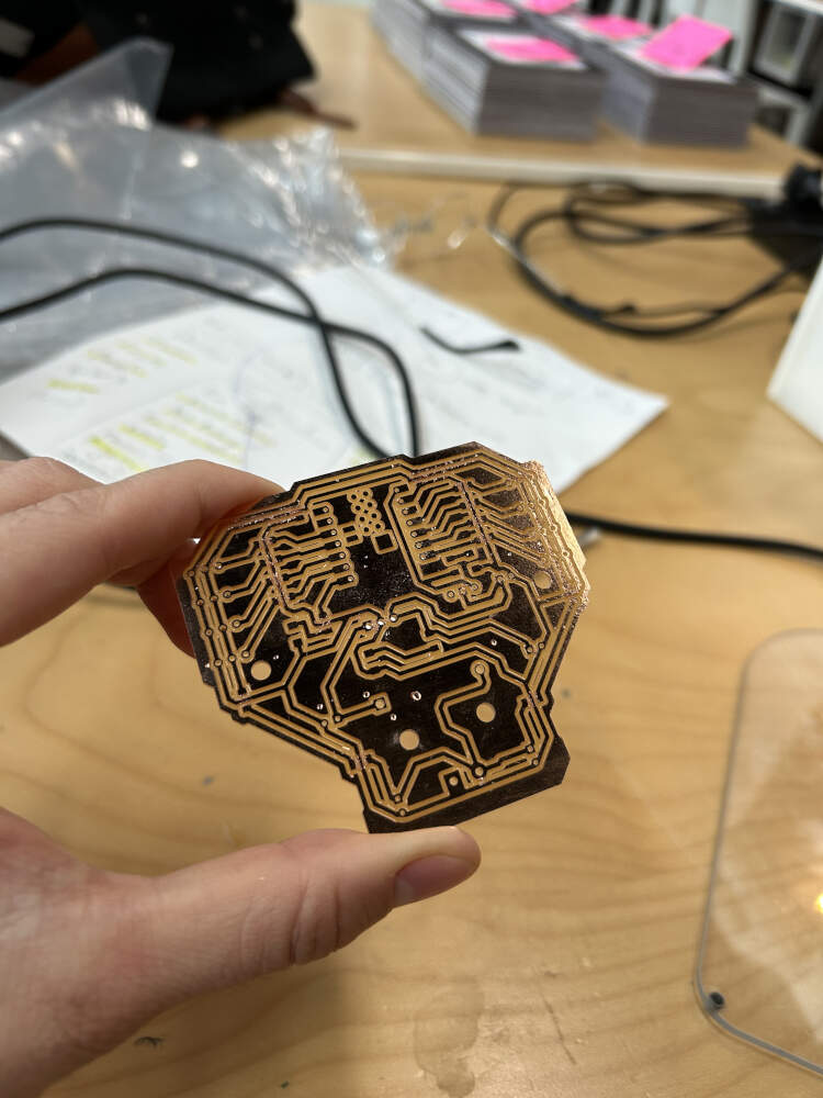
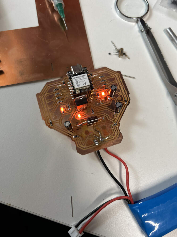
I milled out my board and began soldering components. On slide 5 you'll see that the board is working just fine in terms of electrical flow. Slide 6 is where issues began. You'll see that the switch right after the screw terminal is missing. This is because of a combination of two things, close proximity of components, and hot air. The 470uf capacitors located close to the screw terminal required soldering, but in trying to fix them to the board, I accidentally blasted the switch with too much hot air causing its plastic parts to melt. I had LED's on the board telling me where electricity was actively flowing so when I reconnected the battery some of the LED's were off, so I panicked and started trying to figure out why my microcontroller was not on. I later discovered that an internally melted switch can no longer use the "ON/OFF" functions so I tried jury-rigging a wire from the ON portion of the switch to the power pin. Unfortunately this did not work either because I had replaced so many switches trying to figure out why power not flowing that I did not realize I had damaged the paths leading up to that particular switch. Blasting the board with hot air also meant I had burnt the copper on the my board. Admittedly, it looks pretty cool, but this also didn't help some of the paths on my board, either because solder go into areas I did not want it to, or because the copper lines broke under too much heat.
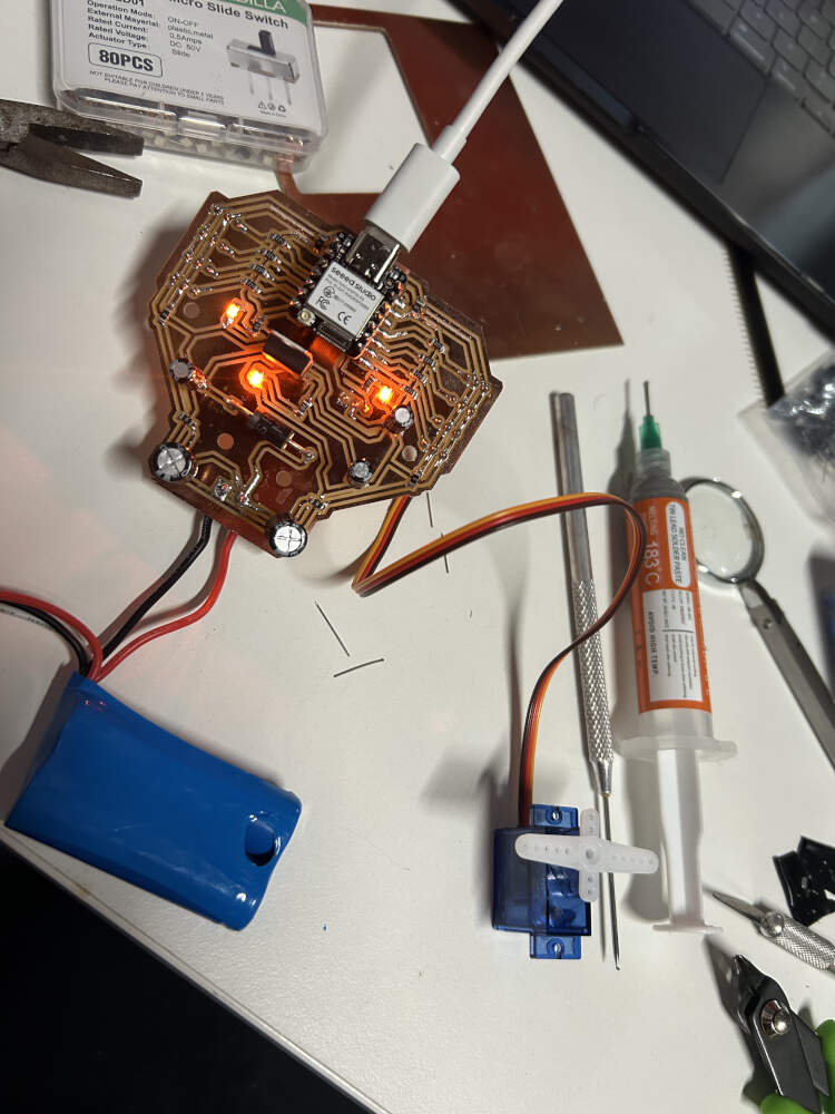
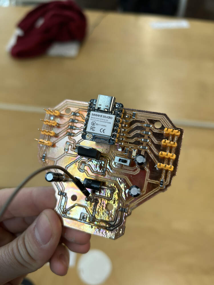
To avoid further issues with my board and soldering, I removed one of the switches. This helped prevent overheating and eliminated a redundant component. The remaining switch was reconfigured from an ON/ON to an ON/OFF setup by removing one of the circuit paths leading back to the power supply.
This change removed the option to power the board through the microcontroller when the battery was unavailable, but that functionality wasn’t necessary. The switch now controls power only to the microcontroller.
Since the first switch was removed, I wanted to retain the ability to cut power entirely. With an ON/ON switch, an external battery could send power directly to the microcontroller through the diode, or the long way around potentially shorting it unintentionally. The new configuration prevents that risk.
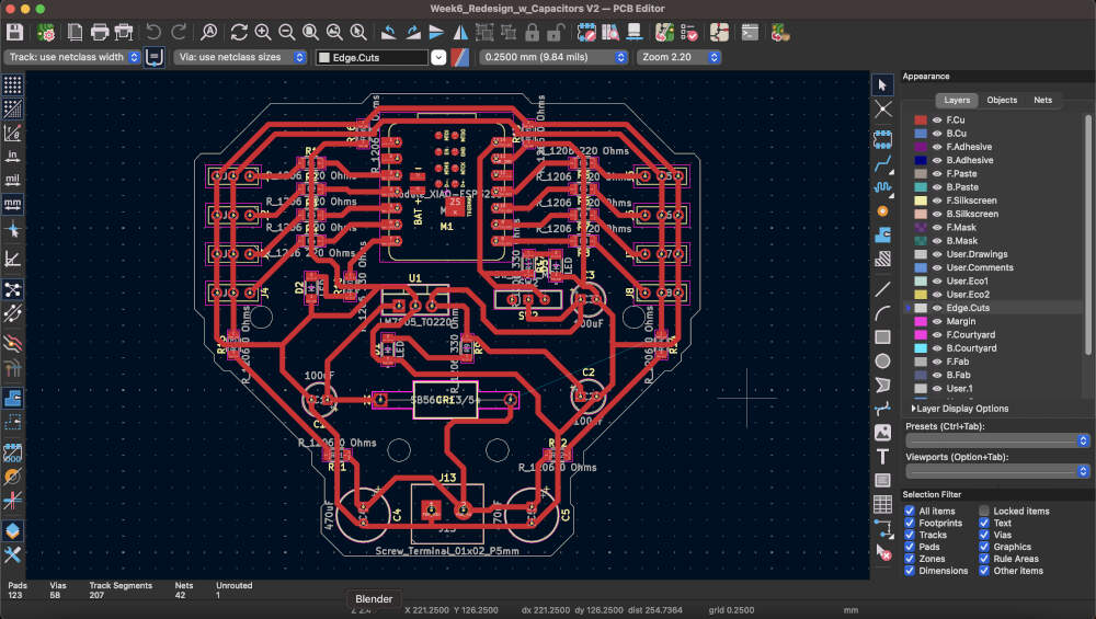
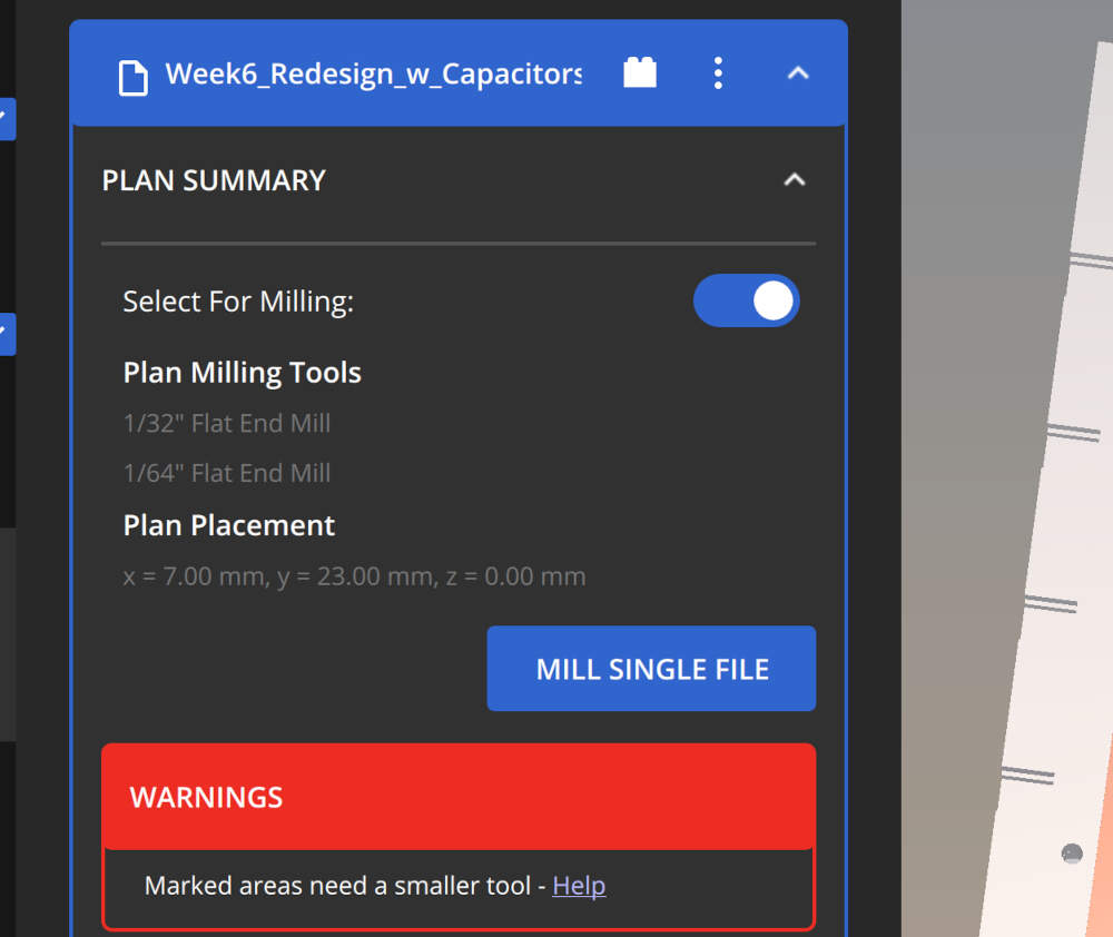
For this design, I widened the circuit paths from 0.5mm to 0.8mm and used a 1/32 bit for most of the cuts. The 1/64 bit was minimally used in this board. There was a stark difference between the two due to the wear on the 1/64 but the use of the 1/32 is a notable improvement in terms of time spent milling, spacing, and room for mistakes while soldering. I soldered the new board and tested it once it was complete. It worked perfectly.
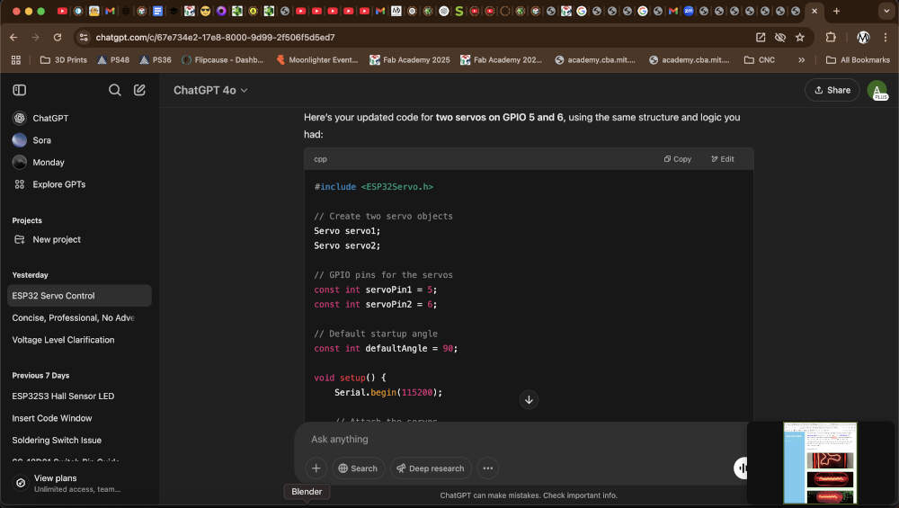
Source code for testing located below. Courtesy of ChatGPT. I uploaded the code to the board. The code was written in a manner that allowed the user to utilize commands in Arduino's serial monitor to change the angle of the servos. When in the serial monitor I would type in "180,180" or "90,45" and the servos would set themselves at either the same angles or two different angles depending on the intent of the user. This can be seen in the video above.
        #include <ESP32Servo.h>

        // Create two servo objects
        Servo servo1;
        Servo servo2;

        // GPIO pins for the servos
        const int servoPin1 = 5;
        const int servoPin2 = 6;

        // Default startup angle
        const int defaultAngle = 90;

        void setup() {
            Serial.begin(115200);

            // Attach the servos
            servo1.attach(servoPin1);
            servo2.attach(servoPin2);

            servo1.write(defaultAngle);
            servo2.write(defaultAngle);

            Serial.printf("Servo1 on GPIO %d and Servo2 on GPIO %d initialized to %d degrees\n", servoPin1, servoPin2, defaultAngle);
            Serial.println("Enter angles as 'angle1,angle2' (0-180), e.g., '90,45'");
        }

        void loop() {
            if (Serial.available()) {
                String input = Serial.readStringUntil('\n');
                input.trim();

                int angle1, angle2;
                if (sscanf(input.c_str(), "%d,%d", &angle1, &angle2) == 2) {
                    if (angle1 >= 0 && angle1 <= 180 && angle2 >= 0 && angle2 <= 180) {
                        servo1.write(angle1);
                        servo2.write(angle2);
                        Serial.printf("Servo1 set to %d degrees, Servo2 set to %d degrees\n", angle1, angle2);
                    } else {
                        Serial.println("Invalid input. Each angle must be between 0 and 180.");
                    }
                } else {
                    Serial.println("Invalid format. Example: '90,45' to set the servos.");
                }
            }
        }
This week's group assignment consisted of measuring the power consumption of an output device. Power consumption is calculated using the formula Power (P) = Voltage (V) x Current (I). Power is measured in watts, V in volts, and current in amps. Both Vicky and Augusto have been using servos so they decided to measure the power consumption of a servo motor.
To measure power consumption we first used a multimeter. From the video you can see that starting and stopping the servo motors creates a drop in the voltage readings. When off the voltage readings are set around 7.5-7.52 volts. But when operating, the three servos drop the voltage between 7.38-7.42 volts. While interesting seeing the effects of on/off output devices, we realized that we still needed to obtain an amps reading to calculate power consumption. For this reason we decided to switch over to the DC Power Supply we had in the space, which can provide voltage and amperage readings while also calculating wattage consumed for you. Additionally we started off by removing two of the three servos so we could establish the averages for just one first.
To use the DC Power Supply, we made sure to hook up the red clamp to the power line and the black clamp to the ground line. Using the power supply we could choose how many volts and amps the power supply was providing to the board. We maxed out the amps at 3.23 and we chose three different voltage levels to focus on with our one servo.
- The first level was 2.7 volts. This level was chosen because it was the minimum voltage required to power the servo motor. At this level the amps would often reach 0.34, and if consistent, the wattage would be 0.92.
- The second level was 5 volts, matching the voltage provided by a pin on both the RP2040 and ESP32S3 microcontrollers, which Vicky and Augusto had been using, respectively. The amps would often reach 0.63, and if consistent, the wattage would be 3.15.
- The third level was 7.4 volts, the voltage provided by Augusto’s external battery currently in hopes of being used for his final project. The amps would often reach 0.84, and if consistent the wattage would be 6.22.
Throughout these tests we realized that increasing voltage would increase amperage. Upon further research we learnt that this was an effect of Ohm’s Law. Since our resistance had remained constant throughout testing of the board and its outputs, the volts had remained directly proportional to the amps.
Copyright 2025 Augusto Vanegas - Creative Commons Attribution Non Commercial Source code hosted at gitlab.fabcloud.org