
Group Assignment:
- Measure the power consumption of an output device
- Document your work on the group work page and reflect on your individual page what you learned.
Individual Assignment:
- Add an output device to a microcontroller board you've designed, and program it to do something
Have you answered these questions?
- Linked to the group assignment page ✅
- Documented what you learned from interfacing an output device(s) to your microcontroller and optionally, how the physical property relates to the measured results. ✅
- Documented what you learned from interfacing output device(s) to microcontroller and controlling the device(s).✅
- Linked to the board you made in a previous assignment or documented your design and fabrication process if you made a new board. ✅
- Explained the programming process/es you used.✅
- Explained any problems you encountered and how you fixed them.✅
- Included original source code and any new design files.✅
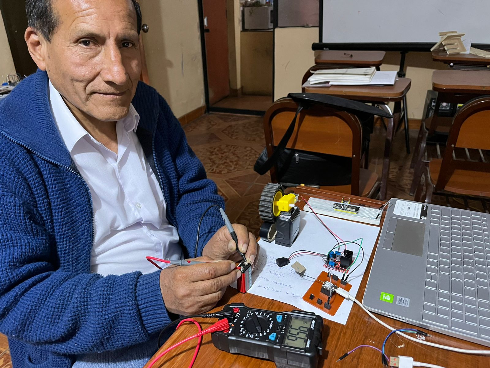
- Included a ‘hero shot’ of your board. ✅
Group Assignment
- Measure the power consumption of an output device.
- Document your work on the group work page and reflect on your individual page what you learned.

Teamwork
During the group project meeting, I had the opportunity to collaborate with my classmate Evelyn, with whom we discussed various measurement concepts. I was also able to explain in more detail how these measuring instruments work, such as the multimeter, which measures various electrical properties, such as voltage, current, and resistance, while a power meter measures the energy consumption of a device or system. The multimeter is a general tool for electrical testing, while the power meter focuses on analyzing energy usage.
With the knowledge acquired, I was able to better understand the use of the instruments and their applications.
Reflections
- What I learned during the group assignment is that it's essential to measure the energy consumption of an output device. In my case, I measured the consumption of a motor, and this allowed me to understand that it's not just about knowing how much energy it uses, but also about analyzing how the system behaves under different operating conditions. By observing consumption at different times, I learned to identify when the motor is working harder, when it's most efficient, and how this can affect the system's overall performance. This experience helped me realize the importance of designing systems that are not only functional, but also efficient and sustainable.
- This experience also made me reflect on the importance of measuring to improve. By understanding the motor's energy consumption, I not only understood its behavior but also considered how to optimize its use in real-world projects. I chose this test because it's part of my final project, which involves designing a security robot. Furthermore, knowing how much energy is required under different conditions allows for better decisions when designing more efficient, durable, and sustainable systems. This is a key step if we want to develop responsible technology adapted to the needs of the environment.
Individual Assignment
- Add an output device to a microcontroller board you've designed, and program it to do something
In week 6, I designed a printed circuit board (PCB) and in week 8, I fabricated my PCB. You can view the full details at the link: Electronics Design, Electronics Production
1.-Output Device: 200RPM 6V Gearmotor
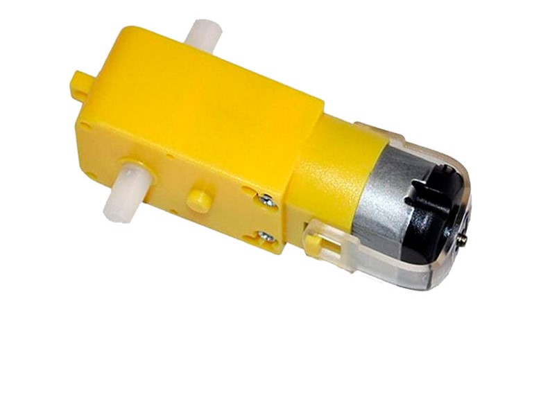
The 6V 200RPM DC geared motor (gearmotor) is a compact actuator designed for applications requiring precise movements and good torque at low speeds. Thanks to its reduction gearbox, it converts high motor speeds into a slower but more powerful output.
This type of motor is widely used in robotics, automation, small mobile vehicles, automatic gates, and control mechanisms.

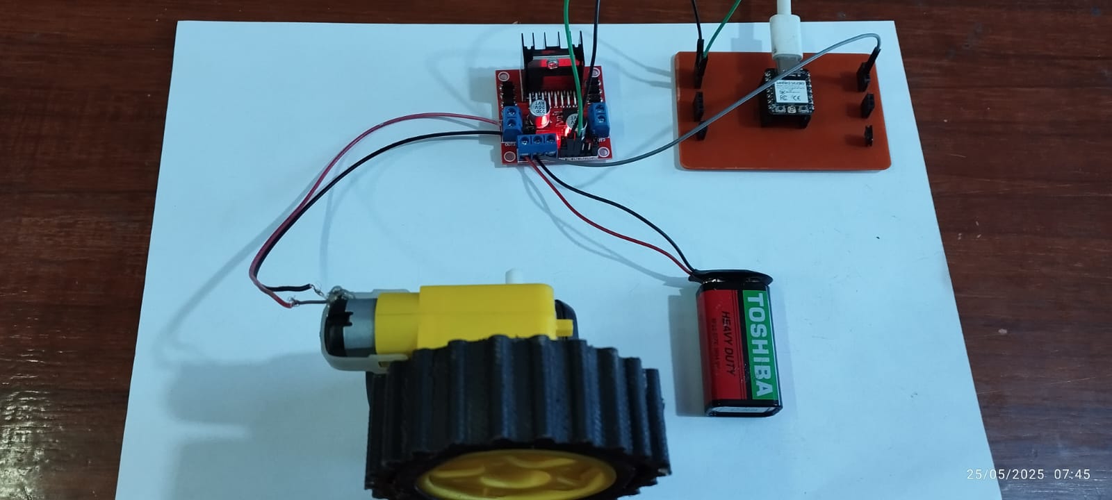
In this exercise, I'm going to implement a wheel coupled to a 6V, 200 RPM DC motor as part of the testing and development process for a traction system. The wheel will be mounted directly on the motor shaft and controlled through a motor driver (such as the L298N) connected to the XIAO ESP32-C3 board.
The wheel represents a fundamental element in the construction of robots or mobile vehicles, so its proper integration with the motor is key to the smooth operation of the project in later stages.
Used Components:
- 6V 200RPM DC Gearmotor
- Wheel attached to motor shaft (approx. 65 mm diameter)
- Motor driver module L298N
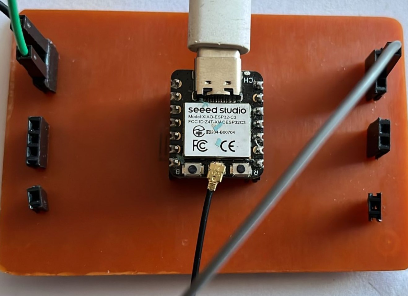
- XIAO ESP32-C3 development board
- 9V external power supply
Electrical Connections:
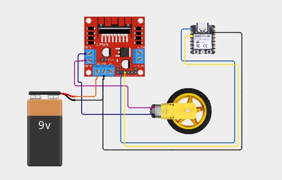
The circuit shows the connections from the XIAO ESP32-C3 microcontroller to the L298N motor driver, which powers and directs the movement of the DC motor with a gearbox and wheel. Communication between the ESP32-C3 and the L298N is via digital pins (IN1, IN2) and a PWM signal (ENA) for speed control.
what difficulties did you have?
I had some difficulties with insufficient current, as the XIAOESP32-C3 microcontroller cannot power the motor directly. The L298N requires a suitable external power supply for the motor.
If the motor doesn't have enough current, it will run weakly or not at all, which is why I used an external power supply, in this case a 9V battery.
Explanation of the Programming Process
1. Inclusion of the library
#include <Arduino.h>
This line includes the core Arduino library. It's especially useful for environments that don't use the classic Arduino IDE (such as PlatformIO), although it's not required for the Arduino IDE.
2. Definition of pins
const int IN1 = 2; // GPIO2 del ESP32-C3
const int IN2 = 4; // GPIO4 del ESP32-C3
- The digital pins GPIO2 and GPIO4 are defined, which will be connected to the IN1 and IN2 pins of the L298N module.
- These pins control the motor's rotation direction.
3. Initial configuration (setup)
void setup() {
    Serial.begin(115200);
    pinMode(IN1, OUTPUT);
    pinMode(IN2, OUTPUT);
}
- Serial.begin(115200);: Begins serial communication to monitor messages from the serial monitor.
- pinMode(IN1, OUTPUT); and pinMode(IN2, OUTPUT);: Configure control pins as outputs.
4. Main loop
a) Move forward
Serial.println("Motor moving forward");
digitalWrite(IN1, HIGH);
digitalWrite(IN2, LOW);
delay(2000);
- IN1 = HIGH, IN2 = LOW → The motor rotates in one direction (forward).
- The motor rotates for 2 seconds (2000 ms).
a) Stop Engine
Serial.println("Motor stopped");
digitalWrite(IN1, LOW);
digitalWrite(IN2, LOW);
delay(1000);
- Both signals LOW → The motor stops.
- Pause for 1 second.
c) Move Back
Serial.println("Motor moving backward");
digitalWrite(IN1, LOW);
digitalWrite(IN2, HIGH);
delay(2000);
- IN1 = LOW, IN2 = HIGH → The motor rotates in the opposite direction (reverse).
- The motor rotates for 2 seconds.
d) Stop engine again
Serial.println("Motor stopped");
digitalWrite(IN1, LOW);
digitalWrite(IN2, LOW);
delay(1000);
- The engine stops again for 1 second.
complete code
#include <Arduino.h>

const int IN1 = 2; // GPIO2 of the ESP32-C3 XIAO
const int IN2 = 4; // GPIO4 of the ESP32-C3 XIAO

void setup() {
    Serial.begin(115200);
    pinMode(IN1, OUTPUT);
    pinMode(IN2, OUTPUT);
}

void loop() {
    Serial.println("Motor moving forward");
    digitalWrite(IN1, HIGH);
    digitalWrite(IN2, LOW);
    delay(2000);

    Serial.println("Motor stopped");
    digitalWrite(IN1, LOW);
    digitalWrite(IN2, LOW);
    delay(1000);

    Serial.println("Motor moving backward");
    digitalWrite(IN1, LOW);
    digitalWrite(IN2, HIGH);
    delay(2000);

    Serial.println("Motor stopped");
    digitalWrite(IN1, LOW);
    digitalWrite(IN2, LOW);
    delay(1000);
}
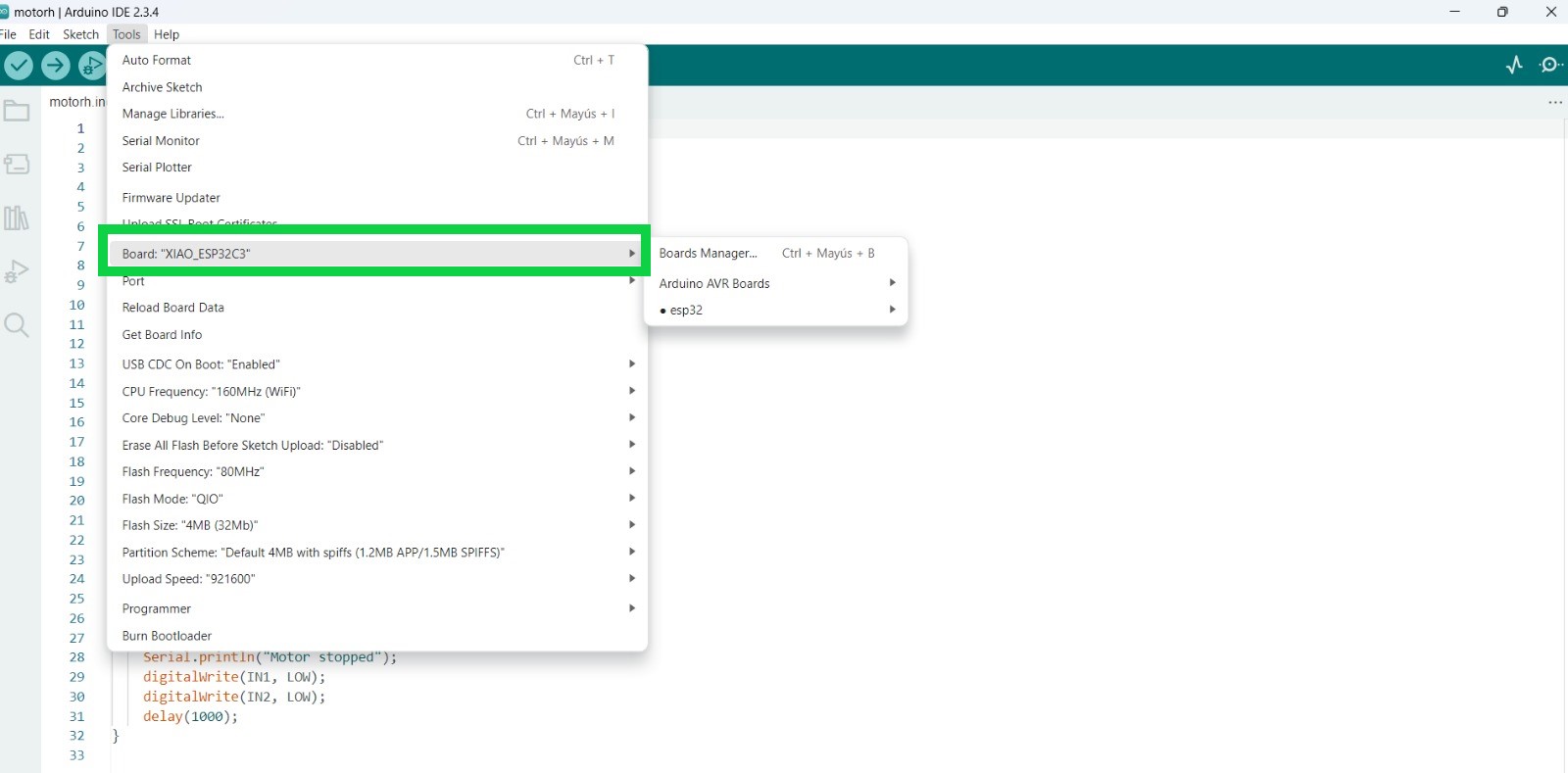
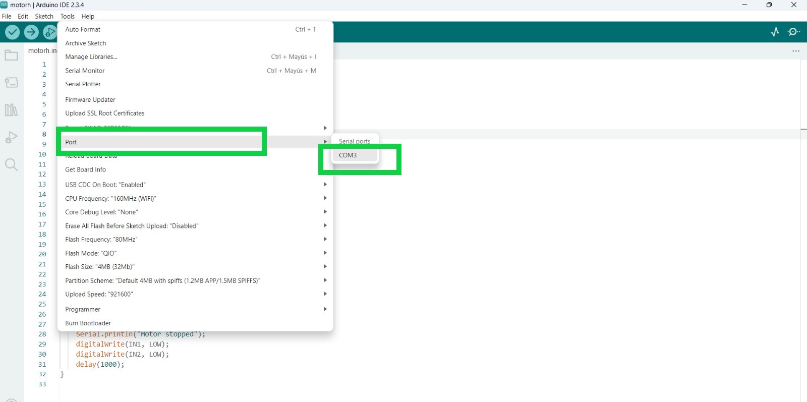
Code upload process in Arduino IDE
In order to load the code into the Arduino IDE environment, we go to the Tools menu and select the board, in this case the XIAOESP32-C3, in the same way we select the COM port, which will be connected to our board.
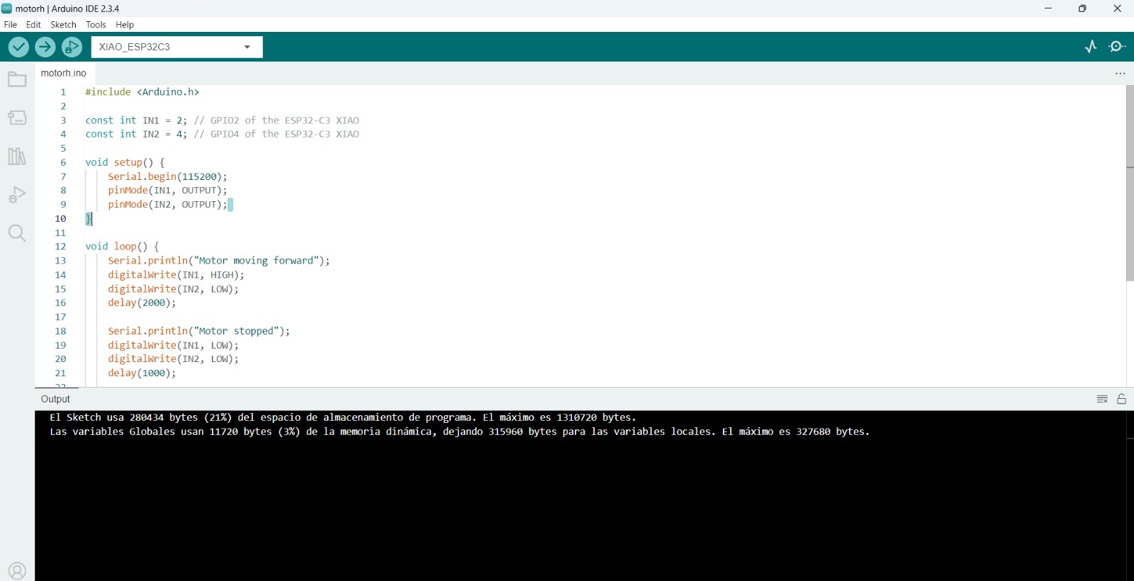
Once we have verified that there are no errors in the code in Arduino IDE, we proceed to load the code into the XIAOESP32-C3 and we can verify that what is programmed in the code is actually being executed.
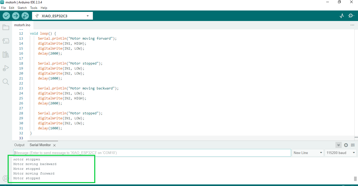
Result
- The exercise successfully demonstrated the control of a DC motor using a XIAO ESP32-C3 microcontroller and a basic H-bridge driver. A simple Arduino program was loaded onto the board, defining two GPIO pins (GPIO2 and GPIO4) as digital outputs to control the motor's direction.
- During execution, the motor moved forward for 2 seconds, stopped for 1 second, reversed direction for another 2 seconds, and stopped again, repeating this cycle continuously. These actions were clearly confirmed by real-time messages displayed on the Serial Monitor.
- The motor responded accurately to the logic levels sent from the ESP32-C3, demonstrating that the pin configuration, code structure, and wiring to the motor driver were correct. This test validated the system's ability to programmatically control motor direction and braking behavior, which is a critical step in developing more advanced robotic systems, such as an autonomous surveillance robot.
2.-Output Device: Servomotor
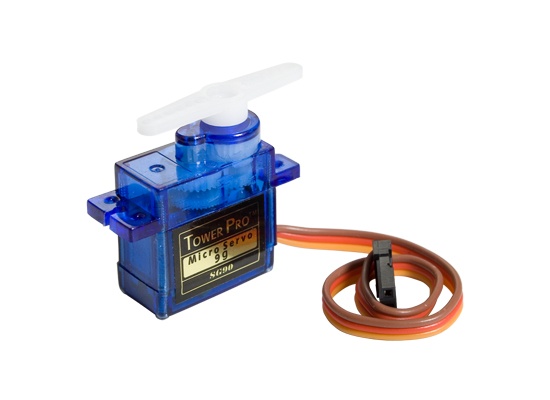
A servomotor is an actuator, or control motor, that allows precise control of an axis' angular position, speed, and acceleration. Essentially, it's an electric motor combined with a feedback system and a controller that allows the axis' position to be adjusted with high precision.
To control a servo motor with the XIAO ESP32-C3 microcontroller, we have followed the following steps:
Necessary Components:
- XIAO ESP32-C3
- Servomotor (SG90 or similar)
- Suitable power supply (if the servo motor requires more current than the ESP32 can provide)
- Connect the servo motor signal pin (PWM) to the GPIO pin of the XIAO ESP32-C3 (GPIO2)
- Connect the power pin (+5V) of the servo motor to the 5V pin of the XIAO ESP32-C3.
- Connect the ground pin (GND) of the servo motor to the GND pin of the XIAO ESP32-C3.
Electrical Connections:
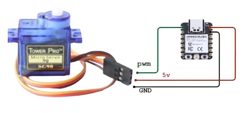
The circuit shows the connections of the servo motor with the XIAOESP32-C3 microcontroller
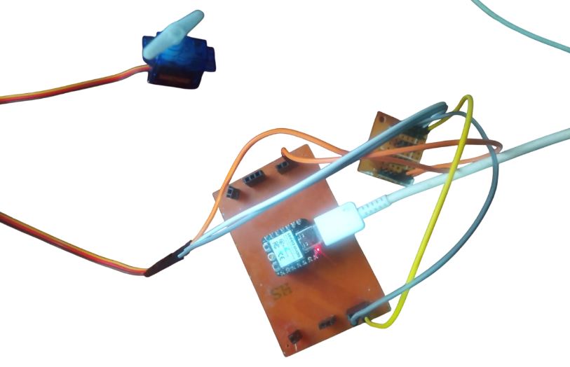
Now we make the connections with the card we designed.
Explanation of the Programming Process
1. Inclusion of the library
#include <ESP32Servo.h> // Official library for ESP32 servos
- Includes the ESP32Servo library, necessary to control servos on ESP32 boards (such as the XIAO ESP32-C3).
- This library allows you to generate PWM signals compatible with servomotors.
2.-Variables and initial configuration
const int servoPin = 2;  // GPIO2 for servo control
Servo miServo;           // Servo object
int pos = 0;             // Current position of the servo
bool girando = true;     // Rotation direction (true = increasing, false = decreasing)
- servoPin: GPIO2 is the output where the servo signal wire is connected.
- miServo: Object that represents the servo motor.
- pos: Stores the current angle of the servo (from 0° to 180°).
- girando: Used to alternate between increasing and decreasing the angle.
3.-loop(): the main loop
if (increasing) {
  pos++;                          // Increase angle
  if (pos >= 180) increasing = false;  // If max angle reached, start decreasing
} else {
  pos--;                          // Decrease angle
  if (pos <= 0) increasing = true;     // If min angle reached, start increasing
}
- If
increasingis true, the servo angle (pos) increases. - When it reaches 180°,
increasingbecomes false, and the angle starts decreasing. - If
increasingis false, the angle decreases until it reaches 0°. - At 0°,
increasingswitches back to true, starting the cycle again.
4.-Move the Servo
miServo.write(pos); // Moves the servo to the 'pos' position
Send the current angle to the servo motor, which will move to that position.
Complete Code
#include <ESP32Servo.h>  // Official library for ESP32 servos

const int servoPin = 2;  // GPIO2 for servo control
Servo myServo;           // Servo object
int pos = 0;             // Variable for position
bool increasing = true;  // Direction control

void setup() {
  Serial.begin(115200);
  myServo.attach(servoPin);  // Initialize servo on GPIO2

  // Configuration to display PWM signal
  Serial.println("Servo_Position,PWM_Value");  // Header for Serial Plotter
}

void loop() {
  // Forward sweep (0° to 180°)
  if (increasing) {
    pos++;
    if (pos >= 180) increasing = false;
  }
  // Backward sweep (180° to 0°)
  else {
    pos--;
    if (pos <= 0) increasing = true;
  }

  myServo.write(pos);  // Move the servo to position 'pos'

  // Send data to Serial Plotter (position and actual PWM value)
  int pwmValue = map(pos, 0, 180, 500, 2400);  // Convert angle to PWM pulse width in microseconds
  Serial.print(pos);       // Angular position (0-180)
  Serial.print(",");       // Separator
  Serial.println(pwmValue);  // Pulse width in microseconds

  delay(15);  // Adjust movement speed
}
Result
3.-Output Device: Stepper Motor
For this test, we'll be using a 28BYJ-48 stepper motor, controlled by a ULN2003 driver and a XIAO ESP32C3 board. The code makes the motor rotate two revolutions clockwise and then two revolutions counterclockwise continuously. A half-phase sequence is used to achieve smoother and more precise movement. In addition, information is sent to the Arduino Serial Plotter to display the status of the control pins (IN1 to IN4) in real time.
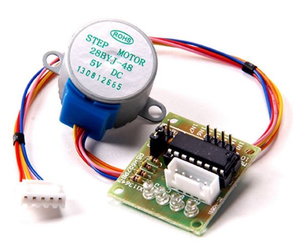
A stepper motor is an electromechanical device that converts electrical pulses into discrete mechanical movements. The shaft of a stepper motor rotates in discrete increments when electrical control pulses are applied to it in the correct sequence.
Electrical Connections:
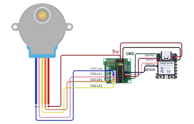
For this exercise, the first thing we have done is to make the connection diagram using the CirkitDesigne, online simulator which will allow us to load the programming code into the Arduino IDE, as well as simulate it.
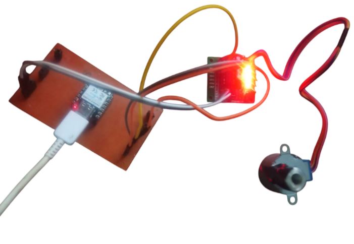
Now we make the connections with the card we designed.
Explanation of the Programming Process
1. Pin Definitions
const int pinMotor1 = 2;  // GPIO2 -> IN1
const int pinMotor2 = 3;  // GPIO3 -> IN2
const int pinMotor3 = 4;  // GPIO4 -> IN3
const int pinMotor4 = 5;  // GPIO5 -> IN4
These define the GPIO pins on the ESP32C3 that are connected to IN1 through IN4 on the ULN2003 driver, which controls the coils of the stepper motor.
2. Motor Parameters
int motorSpeed = 1000;        // Microseconds between steps
int stepsPerRevolution = 4076; // Total steps for a full 360° rotation (28BYJ-48)
These variables control how fast the motor spins and how many steps are required for a full rotation, based on the gear ratio of the 28BYJ-48 stepper motor.
3. Step Sequence (Half-Stepping)
const int stepTable[8] = {
  B1000, B1100, B0100, B0110,
  B0010, B0011, B0001, B1001
};
This array defines the coil activation sequence using half-stepping, which provides smoother and more precise motor movement.
4. Initial Setup
void setup() {
  pinMode(pinMotor1, OUTPUT);
  pinMode(pinMotor2, OUTPUT);
  pinMode(pinMotor3, OUTPUT);
  pinMode(pinMotor4, OUTPUT);
  Serial.begin(115200);
  Serial.println("IN1,IN2,IN3,IN4");
}
Sets the motor control pins as outputs and starts serial communication. The print statement is used for header labels in the Arduino Serial Plotter.
5. Main Loop
void loop() {
  for (int i = 0; i < stepsPerRevolution * 2; i++) {
    executeStep(i % 8, true); // Clockwise
    delayMicroseconds(motorSpeed);
  }
  delay(1000);

  for (int i = 0; i < stepsPerRevolution * 2; i++) {
    executeStep(i % 8, false); // Counter-clockwise
    delayMicroseconds(motorSpeed);
  }
  delay(1000);
}
This continuously rotates the motor two full turns clockwise, then two turns counter-clockwise, with a short delay in between.
6. Step Execution Function
void executeStep(int step, bool clockwise) {
  int currentStep = clockwise ? step : 7 - step;

  digitalWrite(pinMotor1, bitRead(stepTable[currentStep], 0));
  digitalWrite(pinMotor2, bitRead(stepTable[currentStep], 1));
  digitalWrite(pinMotor3, bitRead(stepTable[currentStep], 2));
  digitalWrite(pinMotor4, bitRead(stepTable[currentStep], 3));

  Serial.print(bitRead(stepTable[currentStep], 0)); Serial.print(",");
  Serial.print(bitRead(stepTable[currentStep], 1)); Serial.print(",");
  Serial.print(bitRead(stepTable[currentStep], 2)); Serial.print(",");
  Serial.println(bitRead(stepTable[currentStep], 3));
}
This function activates the appropriate pins for each step, depending on the direction. It also sends the pin states to the Serial Plotter for real-time signal visualization.
Complete Code
	// Pines XIAO ESP32C3 -> Driver ULN2003 (IN1 a IN4)
	const int pinMotor1 = 2;  // GPIO2 -> IN1
	const int pinMotor2 = 3;  // GPIO3 -> IN2
	const int pinMotor3 = 4;  // GPIO4 -> IN3
	const int pinMotor4 = 5;  // GPIO5 -> IN4

	// Configuración motor
	int velocidadMotor = 1000;  // Microsegundos entre pasos (1000 = suave)
	int pasosPorVuelta = 4076;  // Pasos para 360° (28BYJ-48)

	// Secuencia media fase (8 pasos) - Mayor precisión
	const int tablaPasos[8] = {
	  B1000, // Paso 1: IN1 activo
	  B1100, // Paso 2: IN1+IN2
	  B0100, // Paso 3: IN2 activo
	  B0110, // Paso 4: IN2+IN3
	  B0010, // Paso 5: IN3 activo
	  B0011, // Paso 6: IN3+IN4
	  B0001, // Paso 7: IN4 activo
	  B1001  // Paso 8: IN4+IN1
	};

	void setup() {
	  // Configurar pines como salidas
	  pinMode(pinMotor1, OUTPUT);
	  pinMode(pinMotor2, OUTPUT);
	  pinMode(pinMotor3, OUTPUT);
	  pinMode(pinMotor4, OUTPUT);

	  Serial.begin(115200);
	  Serial.println("IN1,IN2,IN3,IN4"); // Encabezados para Serial Plotter
	}

	void loop() {
	  // Giro horario (2 vueltas)
	  for (int i = 0; i < pasosPorVuelta * 2; i++) {
		ejecutarPaso(i % 8, true); // true = horario
		delayMicroseconds(velocidadMotor);
	  }
	  delay(1000);

	  // Giro antihorario (2 vueltas)
	  for (int i = 0; i < pasosPorVuelta * 2; i++) {
		ejecutarPaso(i % 8, false); // false = antihorario
		delayMicroseconds(velocidadMotor);
	  }
	  delay(1000);
	}

	void ejecutarPaso(int paso, bool horario) {
	  int pasoActual = horario ? paso : 7 - paso; // Invierte dirección

	  // Escribe señales en los pines
	  digitalWrite(pinMotor1, bitRead(tablaPasos[pasoActual], 0));
	  digitalWrite(pinMotor2, bitRead(tablaPasos[pasoActual], 1));
	  digitalWrite(pinMotor3, bitRead(tablaPasos[pasoActual], 2));
	  digitalWrite(pinMotor4, bitRead(tablaPasos[pasoActual], 3));

	  // Envía datos al Serial Plotter (1 = HIGH, 0 = LOW)
	  Serial.print(bitRead(tablaPasos[pasoActual], 0));
	  Serial.print(",");
	  Serial.print(bitRead(tablaPasos[pasoActual], 1));
	  Serial.print(",");
	  Serial.print(bitRead(tablaPasos[pasoActual], 2));
	  Serial.print(",");
	  Serial.println(bitRead(tablaPasos[pasoActual], 3));
	}
Result
Conclusions
During my testing, I successfully controlled various output devices—including stepper motors, servo motors, and geared DC motors—using the Seeed Studio XIAO ESP32C3 board. This board proved to be a compact, efficient, and versatile solution for actuator control applications, particularly in automation and robotics projects.
The ESP32C3 provided reliable performance for generating PWM signals and executing digital control sequences, enabling effective operation of motors with or without feedback. However, several considerations and limitations were identified:
- Ensure proper voltage compatibility (3.3V GPIO from the ESP32C3 vs. 5V logic expected by some drivers).
- Use an appropriate external power supply for motors to avoid underpowering.
- For precise applications, stepper motors or motors with encoders are recommended.
- Some drivers like the L298N may not be the most efficient for DC motor control; more modern alternatives should be considered.