CHIP-E
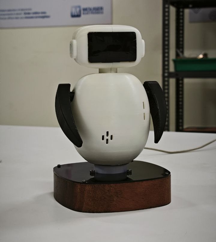
My final project, Chip-E, is an interactive toy designed for children with the goal of reducing their screen time by offering an engaging and playful alternative. The name "Chip-E" was inspired by the tiny chip that powers the toy, giving it life and personality. It was created to feel like a fun companion—one that responds, reacts, and plays along with children.
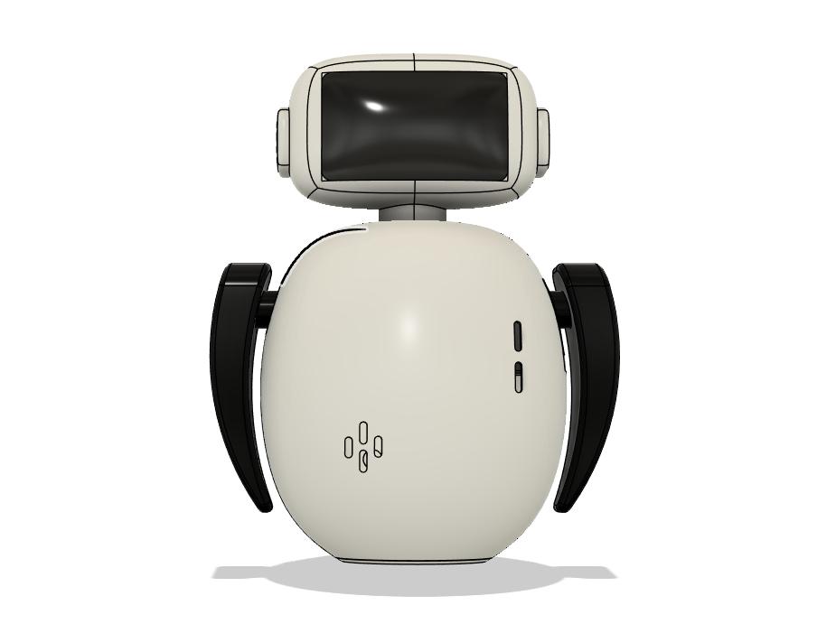
Chip-E can play music and move its arms in sync with the sound, creating the illusion of dancing. Its head features two animated eyes that blink and change expressions, adding charm and a sense of character. Tapping on the top of its head triggers funny sounds and cute eye animations, making it feel responsive and alive.
The toy can also rotate in the direction of sound, giving the impression that it’s listening and turning toward whoever is speaking. One of its most entertaining features is its ability to record a child's voice and play it back, making it feel like a talkative little friend. It is completly voice controlled.
Chip-E runs on a rechargeable battery, making it convenient and easy to use without the need for frequent battery changes. Designed to be more than just a toy, Chip-E encourages children to play, imagine, and interact—without needing a screen.
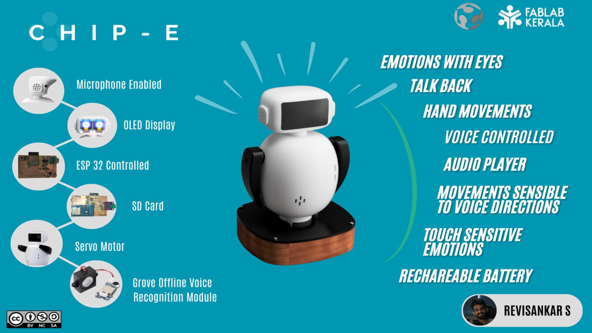
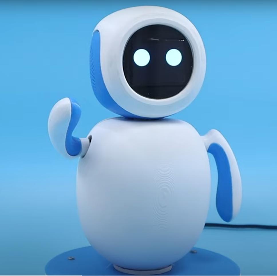
While exploring similar projects for inspiration, I came across one called Emo, developed by Coders Cafe using a Raspberry Pi 4. In contrast, my version is built around an ESP32-WROOM module and features a Talking Tom character. I designed it as a voice-controlled system by integrating the Grove Offline Voice Recognition module. Click here to learn more about Emo.
Design
Parts and systems to be developed include the main body of the toy, moving arms, a rotating base, and a facial display to emulate eye expressions. The body will be 3D printed using PLA for a lightweight and durable structure, while the base combines wood and acrylic for stability and aesthetic appeal. The electronics system is centered around the ESP32 microcontroller, integrated into the base, and includes additional circuitry for motor control and display output. The toy is voice-controlled, utilizing the Grove Offline Voice Recognition module for offline command processing. It also functions as a talking toy, enhancing interactivity. Thorough software-hardware integration and system testing are essential components to ensure seamless performance and user interaction.
Main Parts
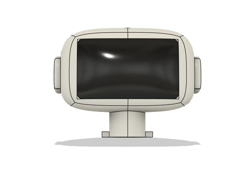
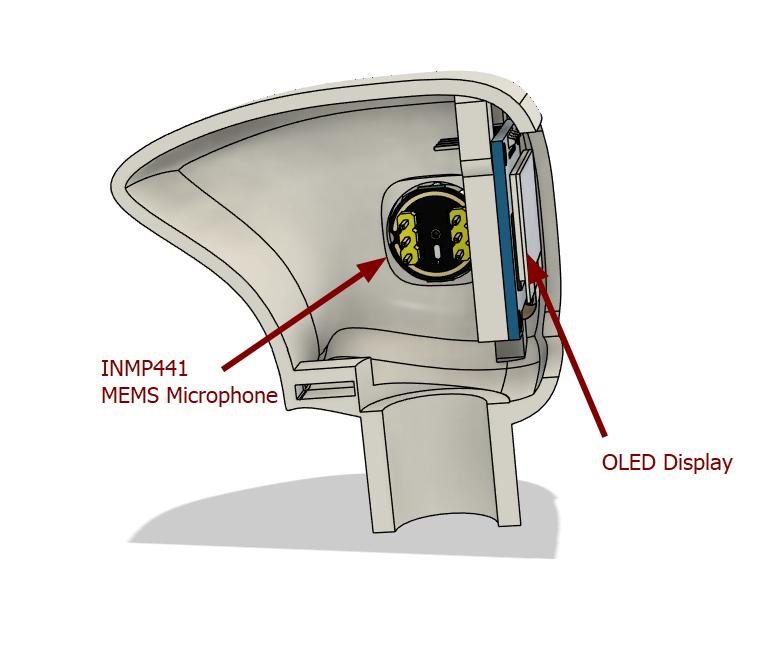
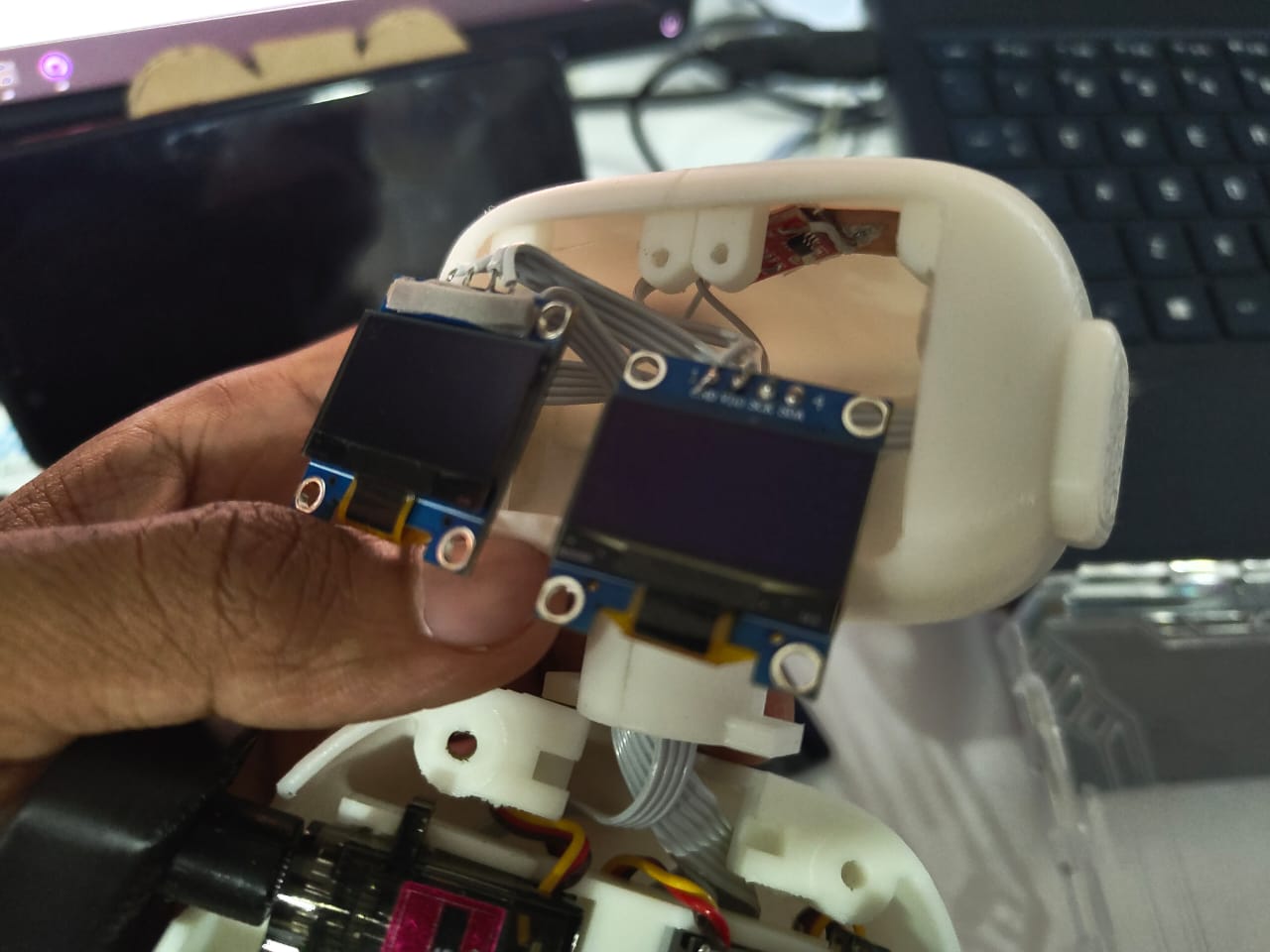
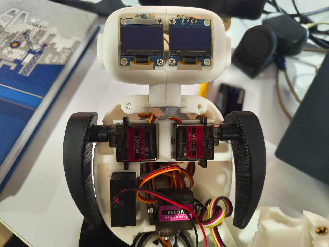
- 3D Printed Head- The toy includes a 3D-printed head equipped with two OLED displays to simulate eye expressions. It features two microphones that work together to enable voice interaction and detect the direction of sound for body rotation. A capacitive touch sensor is also integrated on the top of the head to enhance user interactivity.
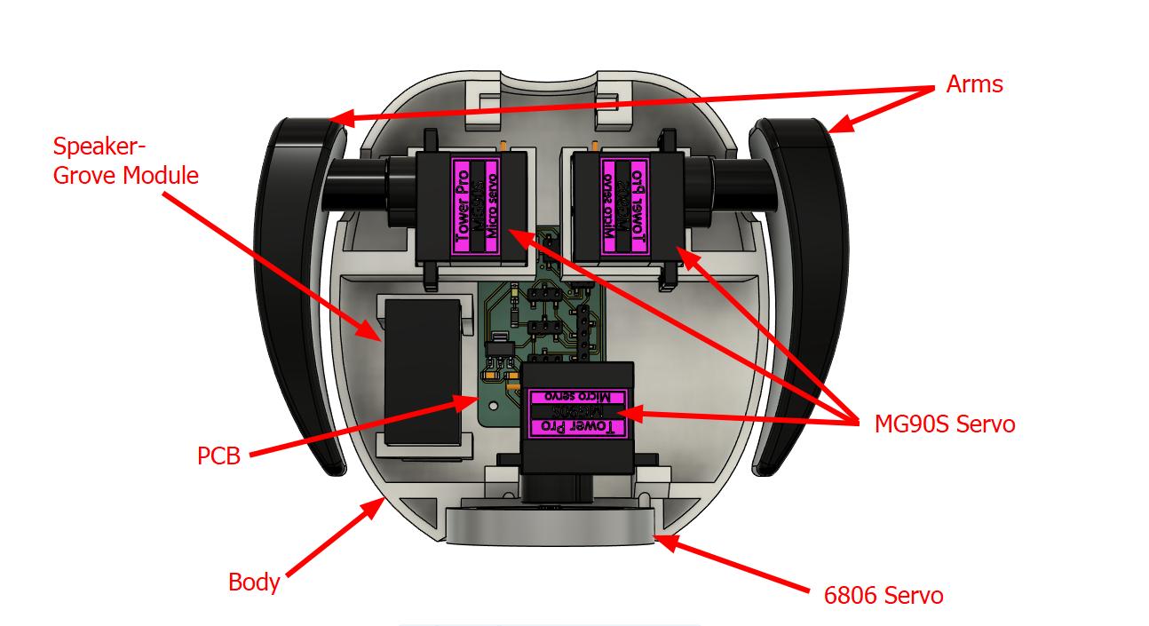
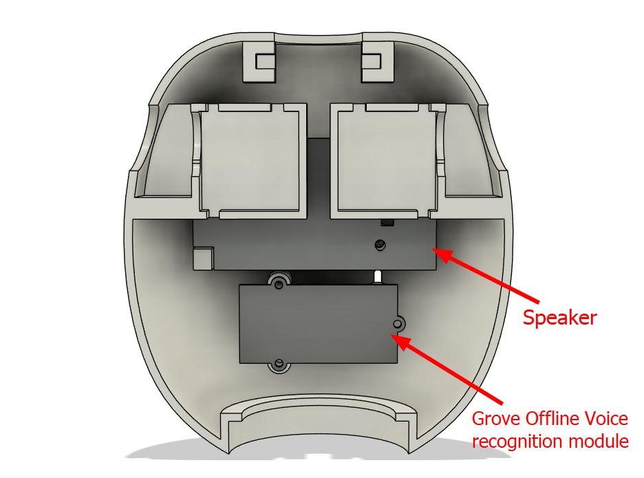
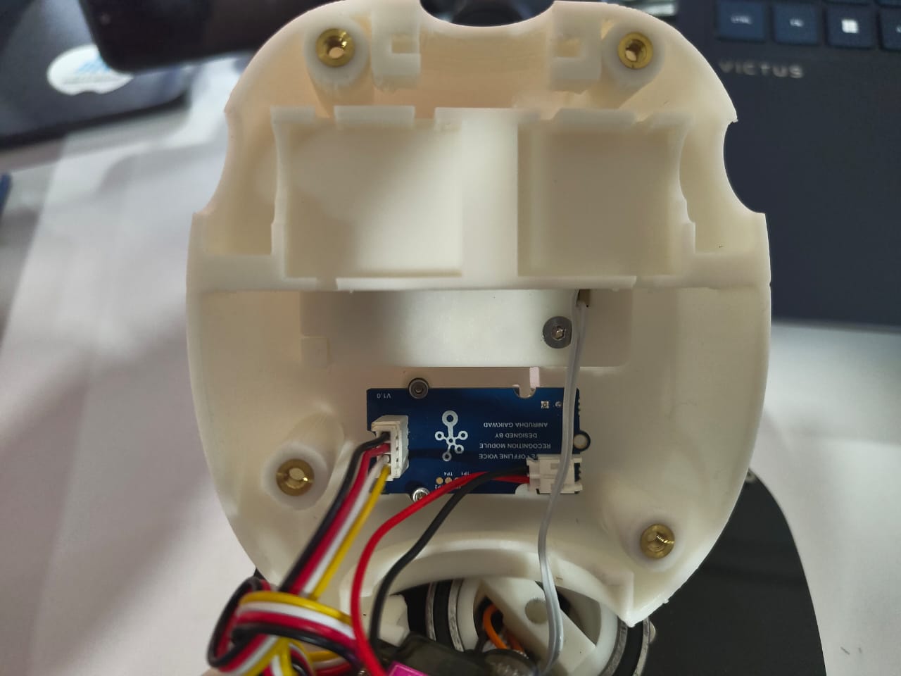
- 3D printed body- The toy features a 3D-printed body that houses key components including a Grove Offline Voice Recognition module, a speaker, and three servo motors—two for arm movement and one for body rotation. A custom-designed PCB is used to manage all connections efficiently, minimizing the number of wires running to the base and ensuring a cleaner, more organized internal layout.
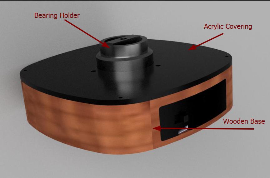
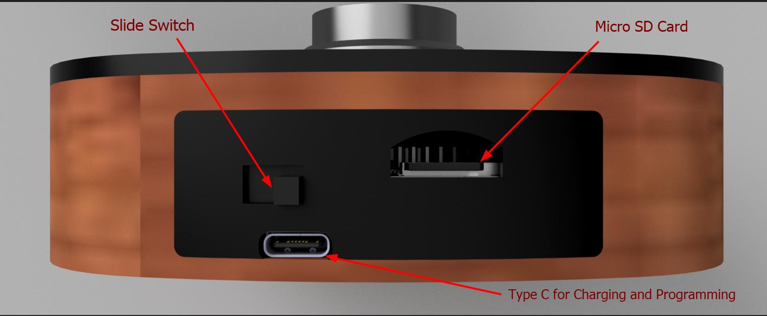
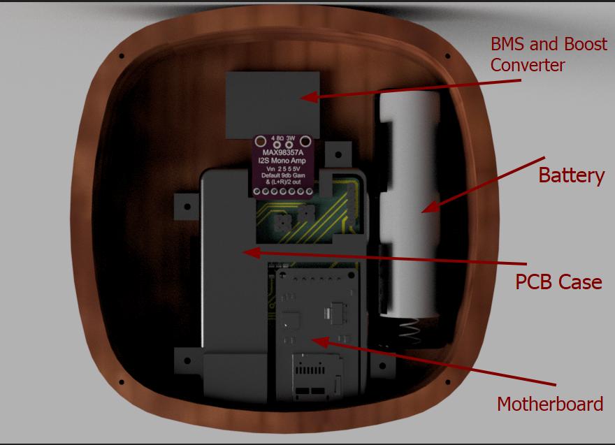
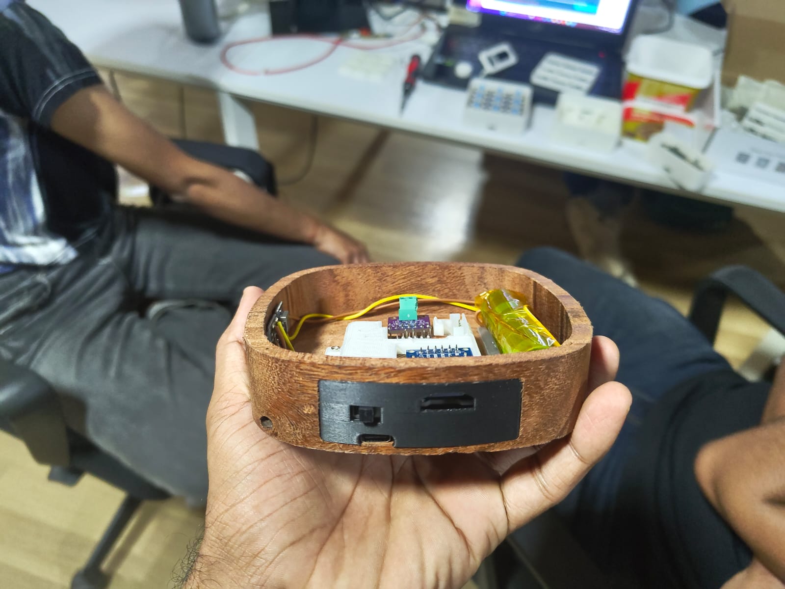
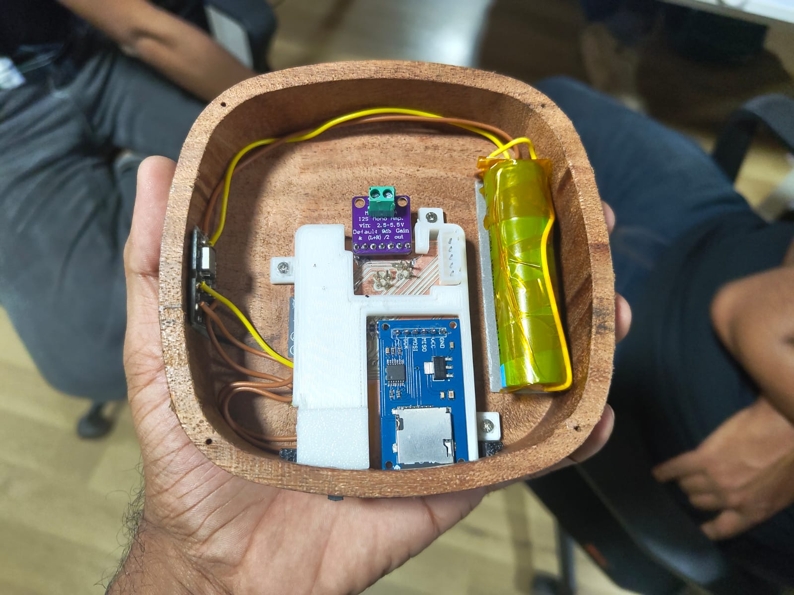
- Wooden base with Acrylic covering- The base is constructed from wood, providing both stability and aesthetic appeal, and is enclosed with an acrylic cover for a polished finish. The battery and the microcontroller PCB are neatly integrated into the base, forming the core of the toy’s power and control system.
 |
 |
 |
 |
 |
 |
Electronics
The electronics played a crucial role in the project and also turned out to be one of the most challenging aspects due to the numerous features involved. I wanted to avoid relying on an external programmer each time I needed to upload code, so I integrated the programming circuitry directly onto the main board. The motherboard was planned to be housed in the base of the toy, which meant several connections had to run from the upper body to the base. To manage this efficiently, I designed an additional board that consolidated all the necessary connections and included a 3.3V voltage regulator. This setup allowed only one 5V line and a ground wire to run from the top to the base, along with the signal wires, significantly reducing the number of cables and simplifying the internal wiring. The second board was neatly embedded within the body of the toy.
Mother Board
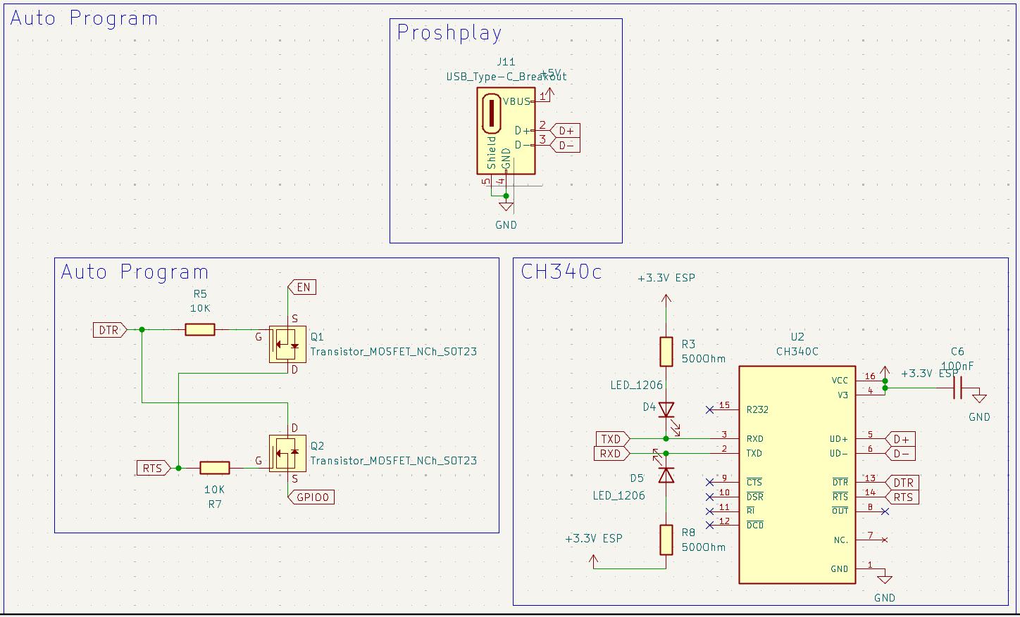
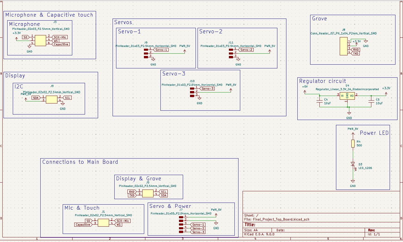
Schematics
The PCB was designed on KiCAD. The project have 2 PCBs with I contains the microcontroller and all the other modules and the other only have connectors to reduce the wires coming to the main boars which is placed below the toy.
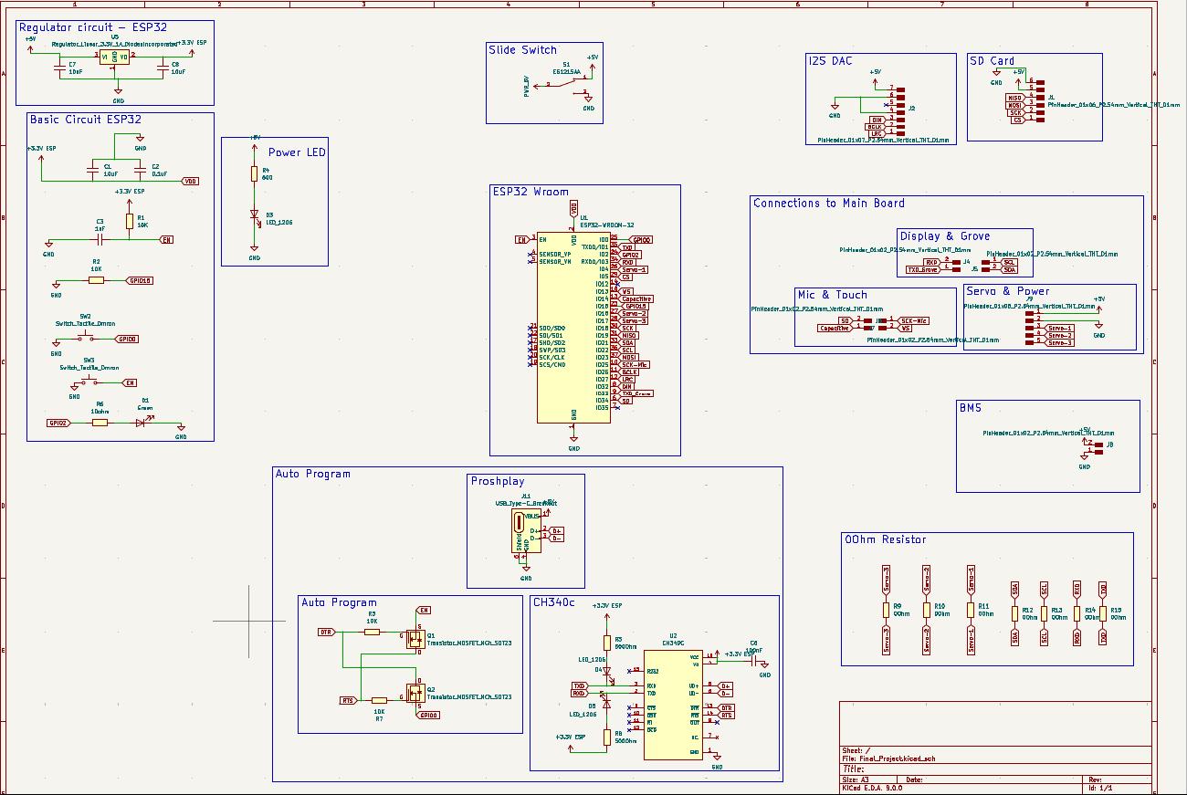
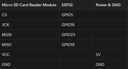
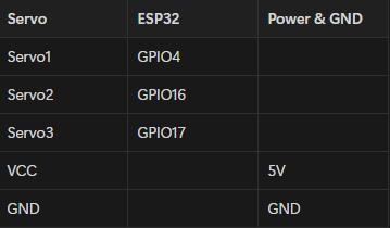
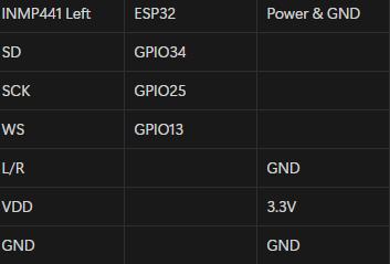
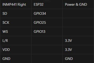
The connections were listed below,
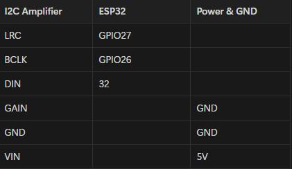
- MAX98357 I2S 3W Class D Amplifier Interface Audio Decoder Module Filterless Board
- Micro SD Card reader module
- Servo
- INMP441 MEMS Microphone
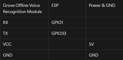
- Grove Offline Voice Recognition Module
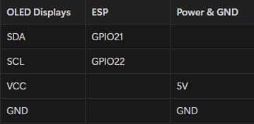
- OLED Display
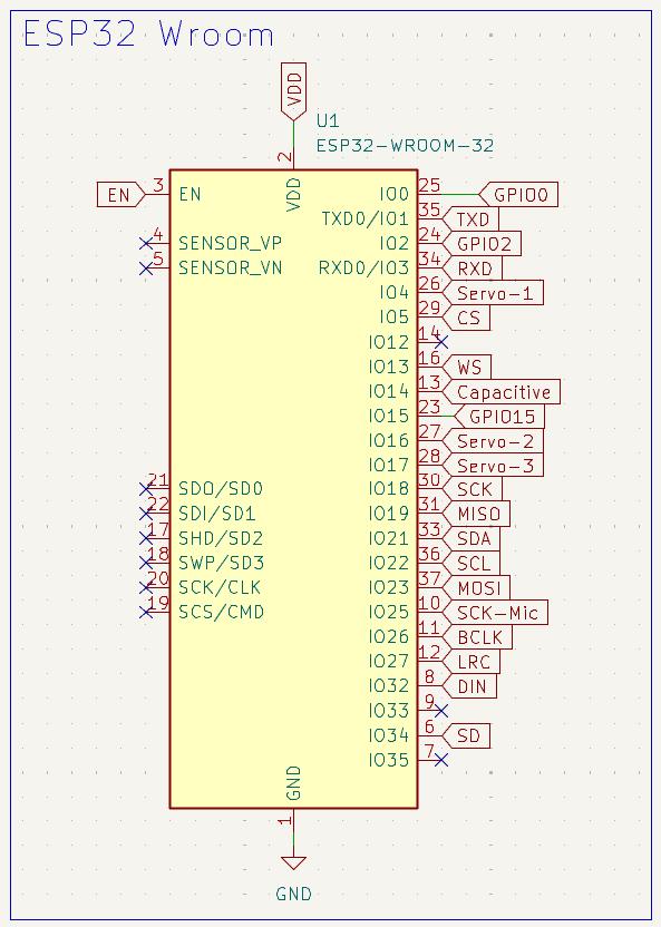
- The Capacitive touch was connected to GPIO14
 |
 |
I integrated the CH340C on to the board so that no external programmer was needed. Also autoprogrammer also included.
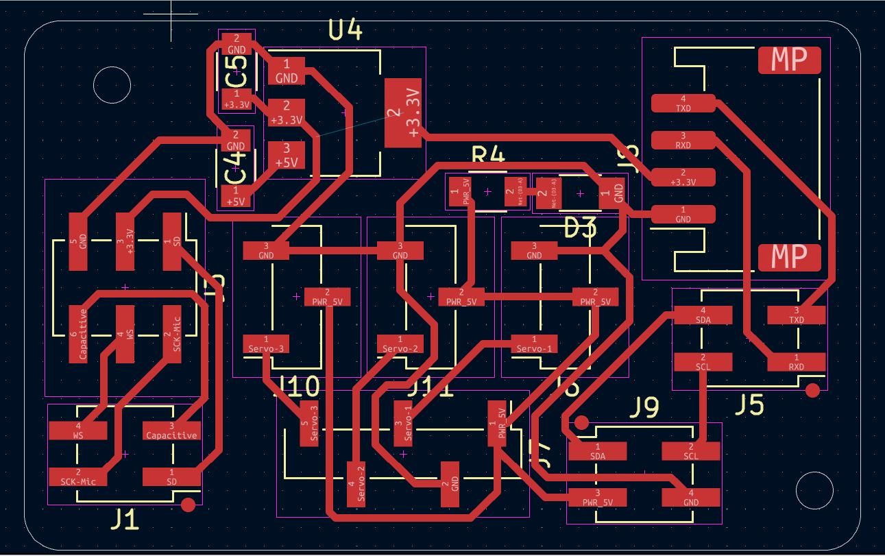
 PCB Design
Due to the size constrain I designed double sided board.
I used the common ground for easiness. The steps for common ground,
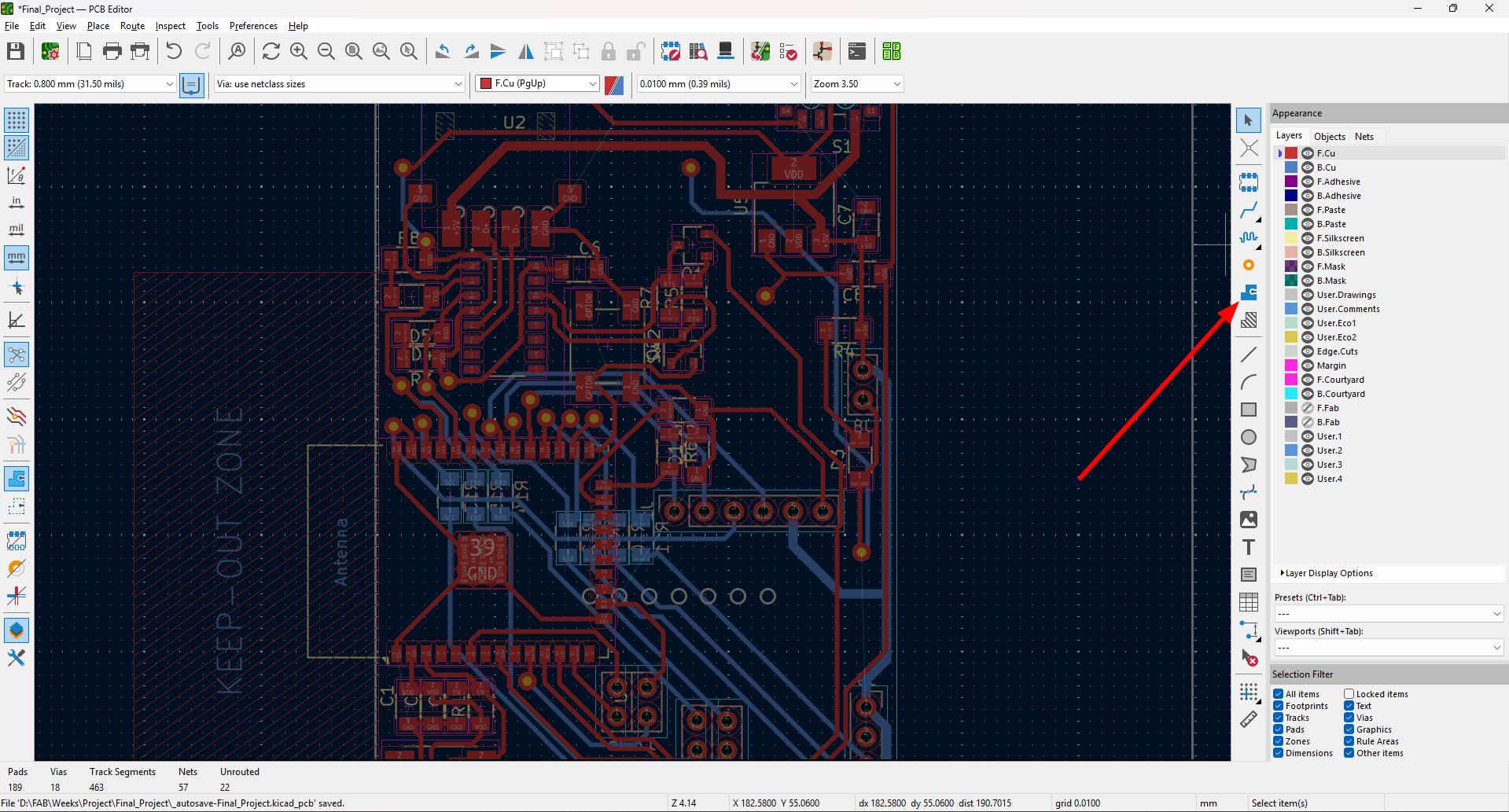
- Select the Draw filled zones options marked in the image
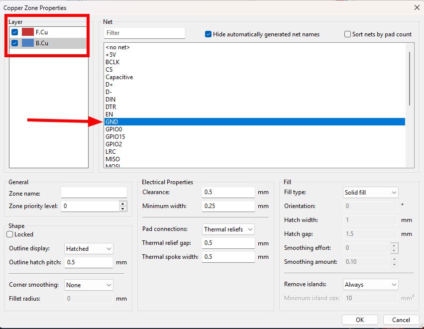
- Select the F.Cu and B.Cu and select GND.
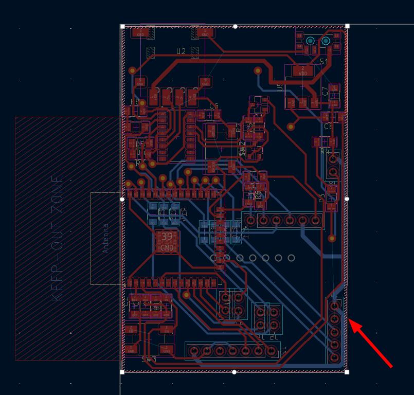
- Draw the areas to fill the GND.
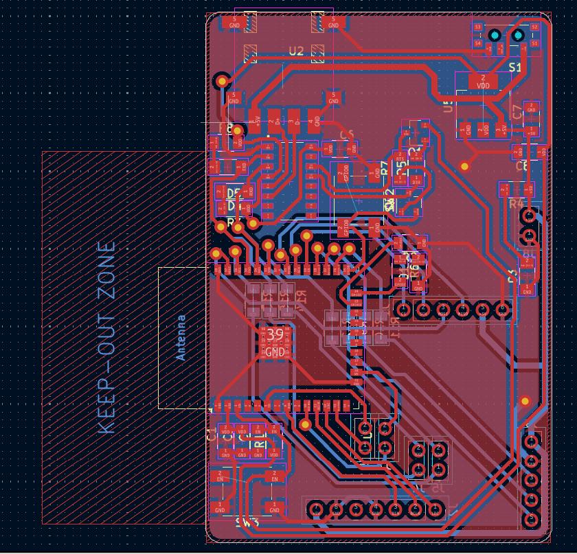
The final PCB looks like this,
Exported the gerber file and made the board. To know more Click here.
Note: The CH340C and Proshplay Type C breakout board Symbol and Footprint was not available in the fab library and can be found at the bottom of this documentation.
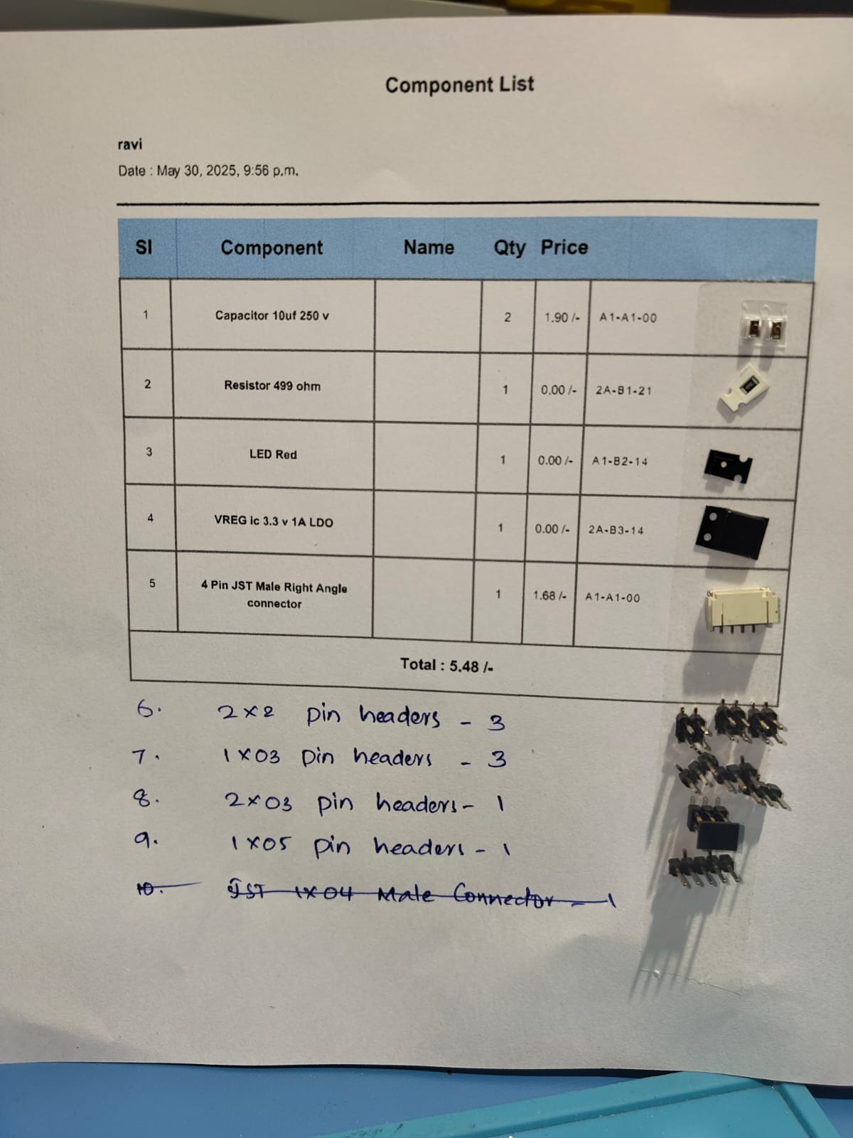
Secondary Board
The board 2 is designed for all the connections so that the power lines going to the base can be reduced. Only one 5V and GND is coming up and is splits in board 2 and also converted into3.3V also.
The Sources I referd for this Project.
- Coders Cafe (Youtube)
- Electronic Wings
- DroneBot Workshop
- Random Nerd Tutorials
- Arduino Forum
- Seed Studio.
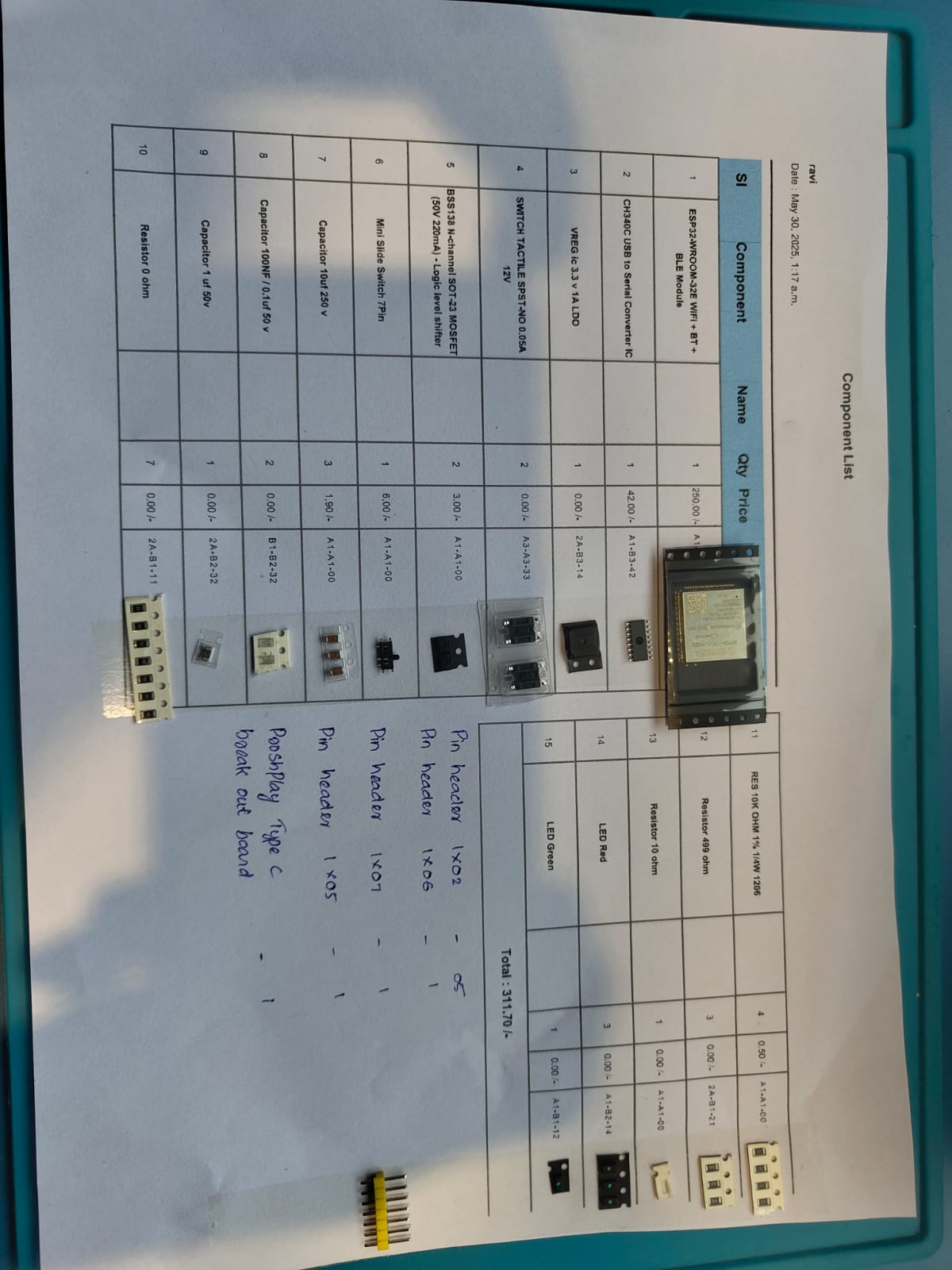
| Sl No | Part | Quantity | Unit Cost | Total Cost | Supplier |
|---|---|---|---|---|---|
| Mechanical Components | |||||
| 1 | SG90 Servomotor | 3 | 149 | 447 | Robu |
| 2 | 6806 Bearing | 1 | 750 | 750 | Amazon |
| 3 | M3 Bolts | 5 | 2.5 | 12.5 | Fab Inventory |
| 4 | M3 Threaded Inserts | 5 | 6.5 | 32.5 | Fab Inventory |
| 5 | M2 Bolts | 17 | 5 | 85 | Fab Inventory |
| 6 | Wood 130 x 130 x 28 mm | 1 | 100 | 100 | Fab Inventory |
| 7 | Acrylic Sheet 150 x 150 x 6 mm | 0.5 sqft | 125 | 125 | Fab Inventory |
| Electronics Components | |||||
| 8 | 0.96 inch SSD1306 OLED Display (128x64) | 2 | 175 | 350 | Robu |
| 9 | INMP MEMS Microphone | 2 | 198 | 396 | Robocraze |
| 10 | Iphone 7 plus speaker | 1 | 299 | 299 | Flipkart |
| 11 | Grove Offline Voice Recognition Module | 1 | 1889 | 1889 | Robu |
| 12 | Micro SD Card Reader Module | 1 | 40 | 40 | Fab Inventory |
| 13 | Micro SD Card | 1 | 398 | 398 | Fab Inventory |
| 14 | Type-C USB 5V 2A Step-Up Boost Converter | 1 | 57.99 | 57.99 | RoboticsDNA |
| 15 | ProshPlay Type C Breakout Board | 1 | 20 | 20 | Fab Inventory |
| 16 | ESP32 WROOM 32E | 1 | 250 | 250 | Fab Inventory |
| 17 | 3.6V Lithium Ion battery | 1 | 131 | 131 | Fab Inventory |
| 18 | Slider Switch | 1 | 7 | 7 | Fab Inventory |
| 19 | MAX98357 I2S Amplifier Module | 1 | 149 | 149 | Rytronics |
| 20 | Touch Switch | 1 | 30 | 30 | Local Shop |
| 21 | Capacitor 10uF | 5 | 1.9 | 9.5 | Fab Inventory |
| 22 | Capacitor 0.1 uF | 2 | 1 | 2 | Fab Inventory |
| 23 | Capacitor 1 uF | 1 | 1 | 1 | Fab Inventory |
| 24 | Resistor 10K | 4 | 0.5 | 2 | Fab Inventory |
| 25 | Resistor 500 ohm | 4 | 1 | 4 | Fab Inventory |
| 26 | Resistor 10 ohm | 1 | 1 | 1 | Fab Inventory |
| 27 | Resistor 0 ohm | 1 | 1 | 1 | Fab Inventory |
| 28 | LED_1206 | 5 | 1 | 5 | Fab Inventory |
| 29 | CH340C | 1 | 42 | 42 | Fab Inventory |
| 30 | VREG IC 3.3V 1A LDO | 2 | 28 | 56 | Fab Inventory |
| 31 | Push Button 6x6mm | 2 | 18 | 36 | Fab Inventory |
| 32 | MOSFET N-Ch SOT23 | 2 | 3 | 6 | Fab Inventory |
| 33 | Slide Switch EG1215AA | 1 | 6 | 6 | Fab Inventory |
| 34 | Conn Header Pin 02x02 | 3 | 5 | 15 | Fab Inventory |
| 35 | Conn Header Pin 01x03 | 3 | 5 | 15 | Fab Inventory |
| 36 | Conn Header Pin 02x03 | 1 | 7 | 7 | Fab Inventory |
| 37 | Conn Header Pin 01x02 | 5 | 4 | 20 | Fab Inventory |
| 38 | Conn Header Pin 01x04 | 1 | 5 | 5 | Fab Inventory |
| 39 | Conn Header Pin 01x05 | 2 | 6 | 12 | Fab Inventory |
| 40 | Conn Header Pin 01x06 | 1 | 7 | 7 | Fab Inventory |
| 41 | Conn Header Pin 01x07 | 1 | 8 | 8 | Fab Inventory |
| 42 | IDC 2x02 Connector Female | 6 | 80 | 480 | Fab Inventory |
| 43 | IDC 2x03 Connector Female | 2 | 110 | 220 | Fab Inventory |
| 44 | JST Connector 1x05 Female | 2 | 11 | 22 | Fab Inventory |
| 45 | JST Connector 1x05 Male | 1 | 5 | 5 | Fab Inventory |
| 46 | PCB Single Side | 1 | 100 | 100 | Fab Inventory |
| 47 | PCB Double Side | 1 | 150 | 150 | Fab Inventory |
| Total | ₹6806.49 | ||||
Fabrication
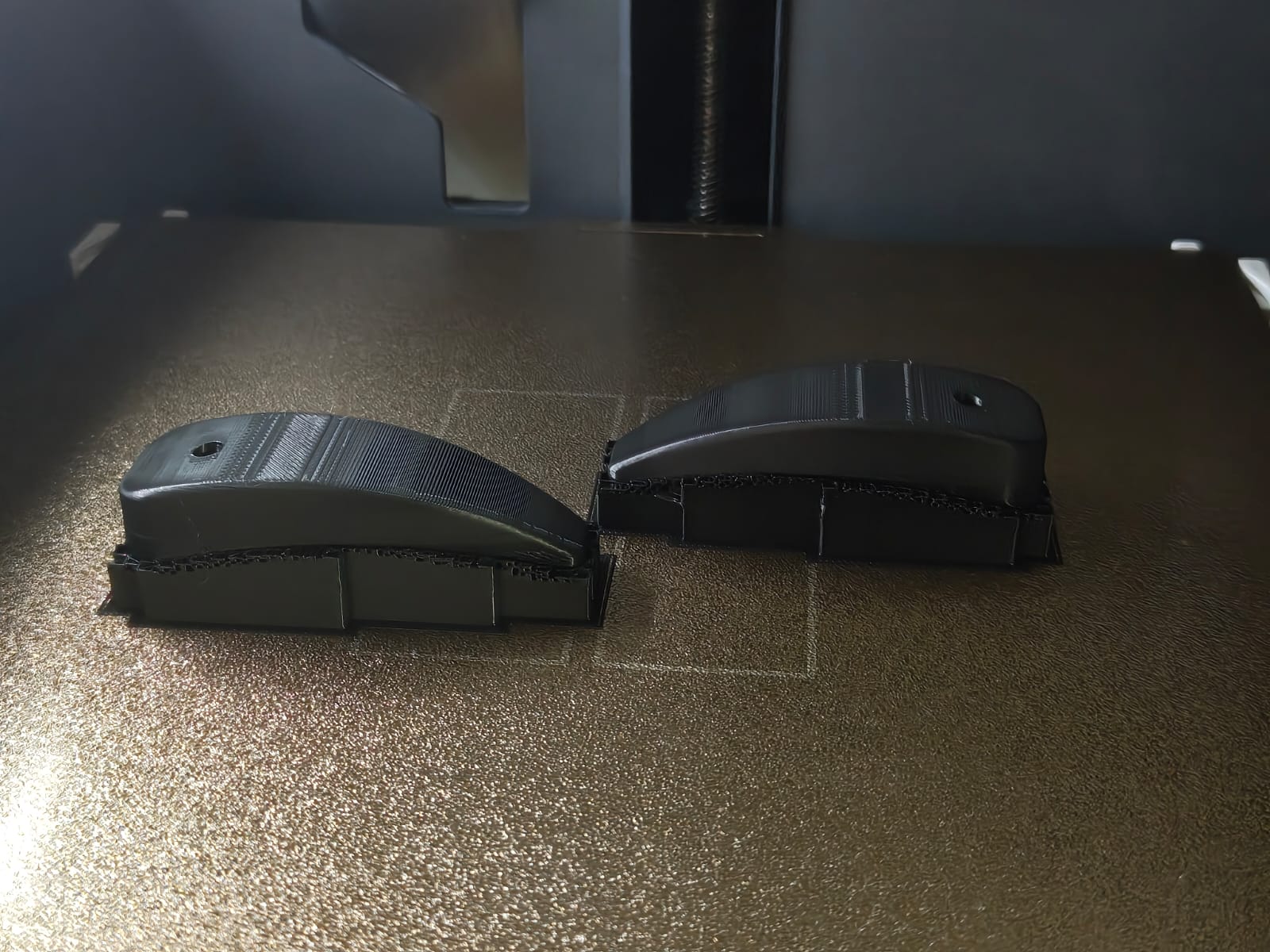
The majority of my components were fabricated using 3D printing. The base section was milled using the TRAK DPM RX2 milling machine available in our lab, while the top cover of the base and the speaker enclosure were created using laser cutting and the PCB was milled in the Roland Modela MDX-20.
3D Printing
I used Bambu P1S and Bambu X1 Carbon 3D printers for my project. The head, Body, Arms and the enclosure for the speaker were needed to be 3D printed.
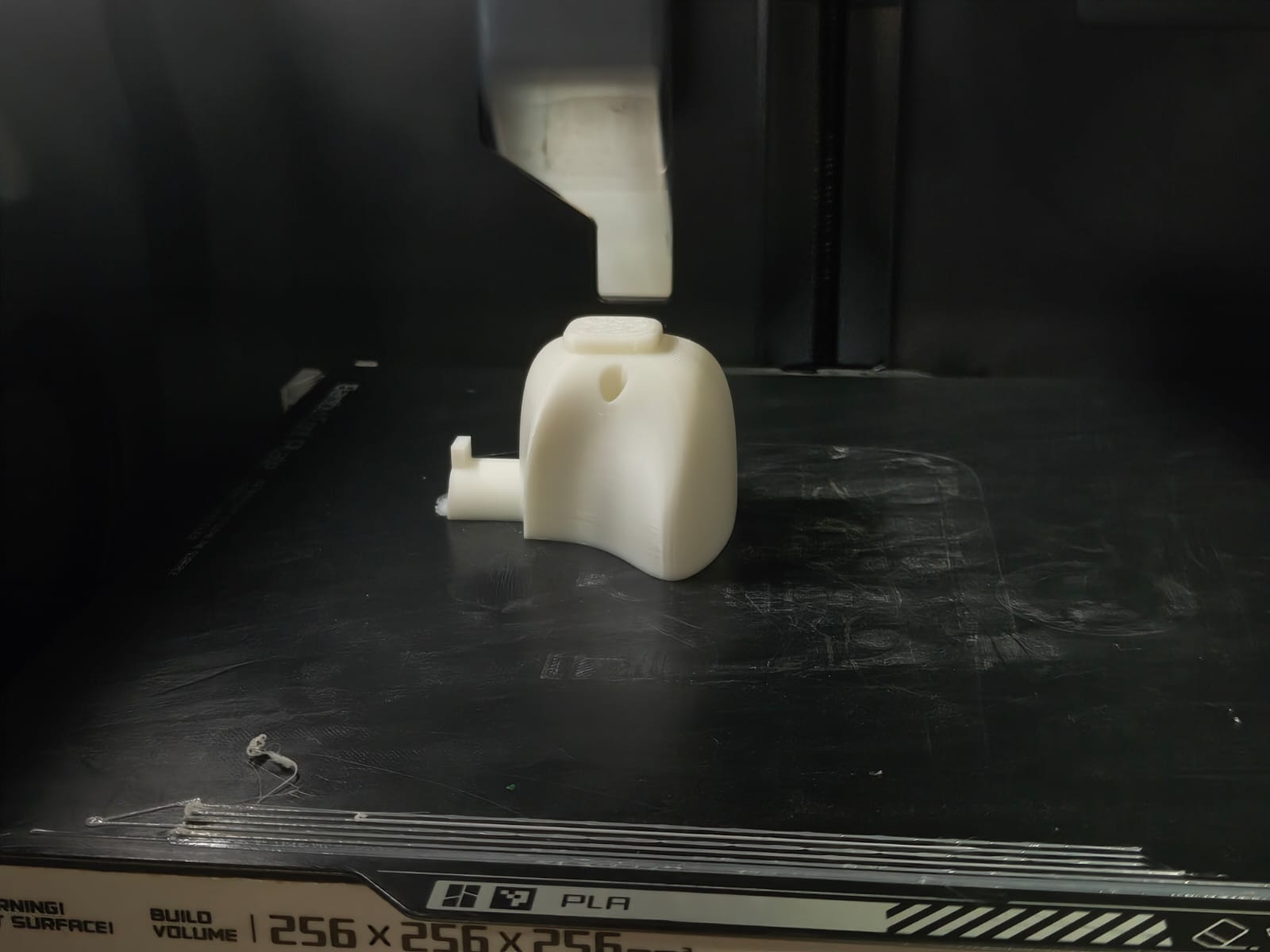 |
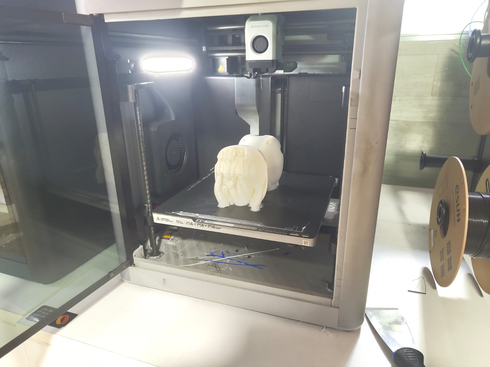 |
Exporting the 3d file as .stl file and slicing all included in the 3D Printing and Scanning Week.
Base
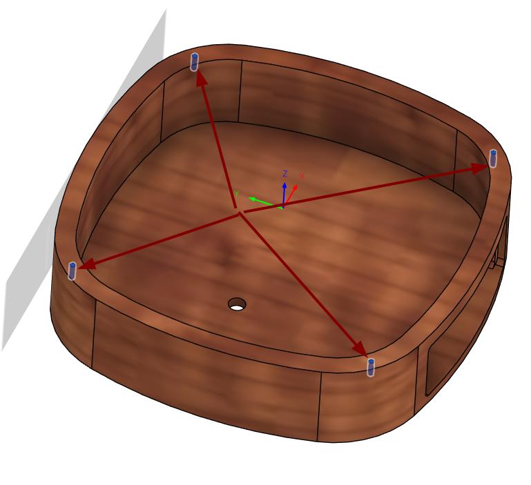
The base I planned to made out of wood. I used the ProtoTRAK DPM RX2 milling machine in our lab for milling the wood. I CAM it in the Fusion 360 manufacturing workspace and postprocessed it for the machine.
Initially I open the manufacturing workspace of fusion 360 and in setup option I specified the stock size and the stock point of the workpiece.
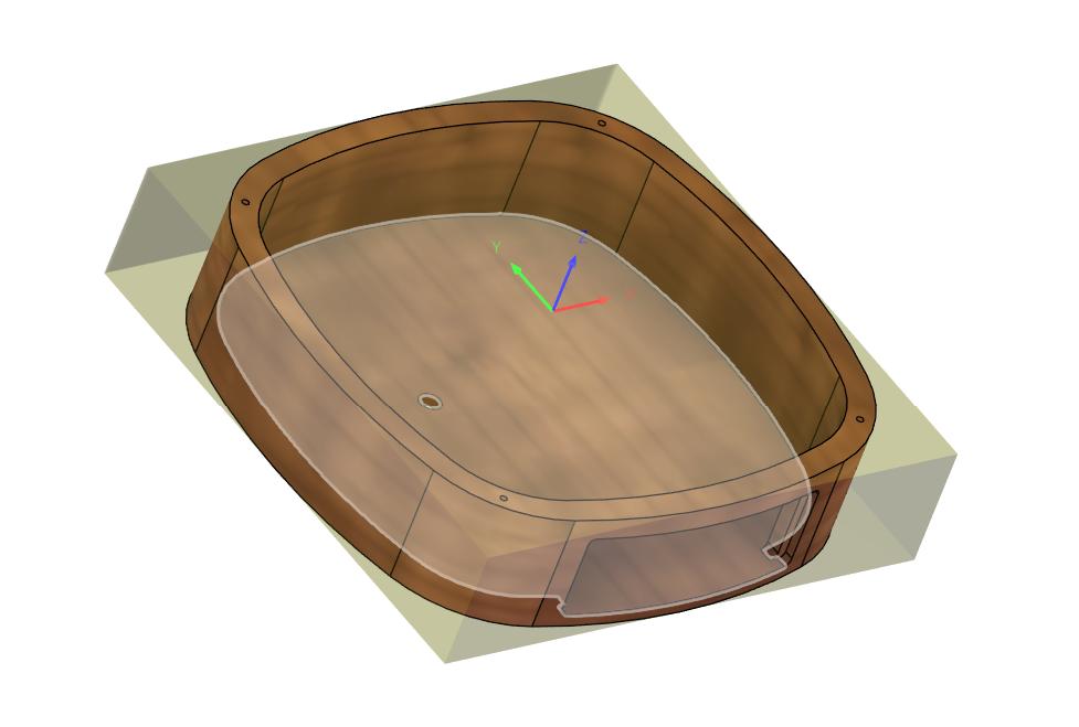
3D Pocket
I needed to remove the material from the inside part of the wood to get the inside of the base. So I chose 3D pocket toolpath. Selected the inside containment used the following parameters
Tool- 16mm insert cutter
Spindle speed- 3000rpm
Feed Rate- 2000rpm
Surface Speed- 150.796m/min
Maximum roughing stepdown- 0.6mm
Drill
As I need to access the reset button of the mother board, I made a hole on the base where the reset button comes. I used the drill toolpath for this.
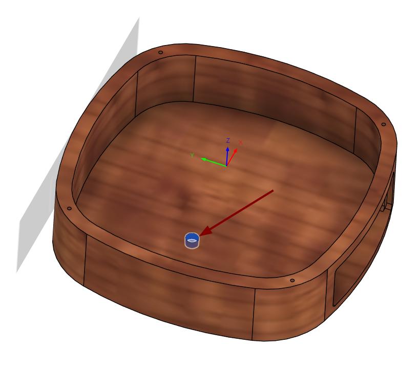
Tool- 5mm Drill
Spindle Speed- 2000rpm
Plunge Feedrate- 50mm/min
Surface Speed- 31.4159m/min
Cycle Type- Deep drilling- full retract
Pecking depth- 1mm
Drill
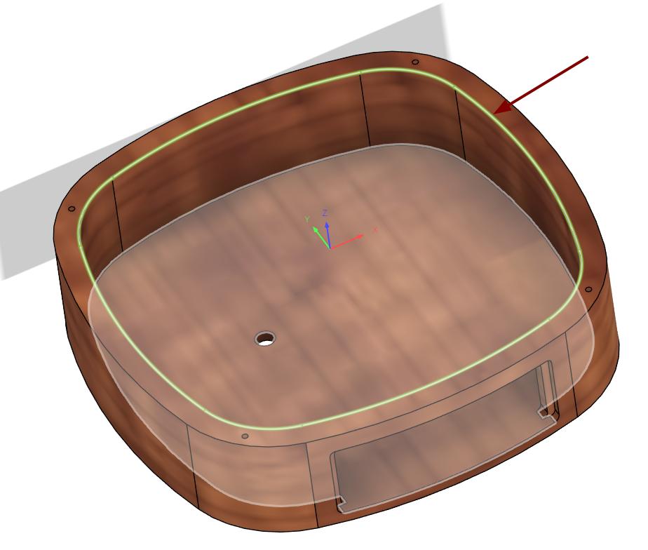
The base is going to be covered with acrylic and it is holded in place by M2 Screws. So I drilled 1.7mm holes on the base for the screws.
Tool- 1.7mm Drill
Spindle Speed- 2000
Plunge Feedrate- 50mm/min
Surface Speed- 10.6814m/min
Cycle Type- Deep drilling- full retract
Pecking Depth- 0.3mm
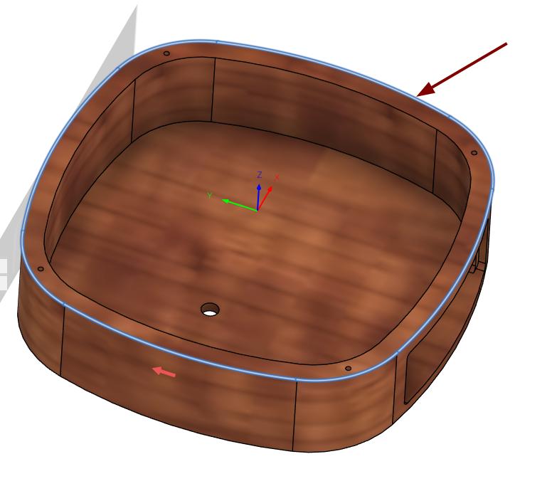
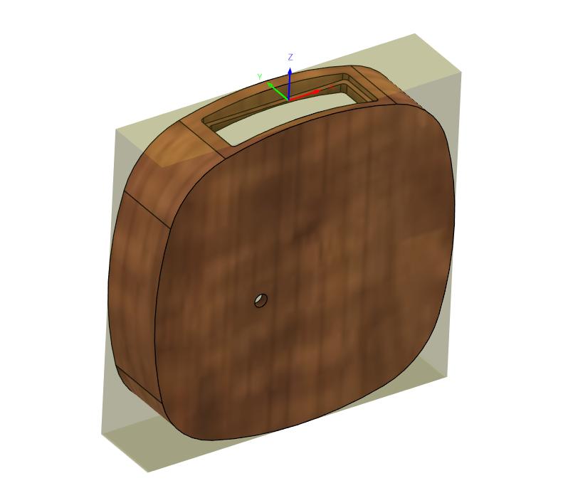
3D Contour
After all these operations, I removed the materials from the wood to get the outer part of the base. Iused the 3D Contour toolpath for that.
Tool- 16mm insert cutter
Spindle Speed- 3500rpm
Cutting Feedrate- 2000mm/min
Surface Speed- 175.929m/min
Maximum roughing stepdown- 0.8mm
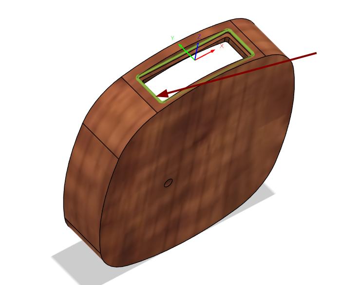
Simulation
Using the Ramp tool path from the 3D tool paths for milling the side. used the following parameters for milling.
Tool- 3mm 4Flute Endmill
Spindle Speed- 3000rpm
Cutting Feedrate- 500mm/min
Surface Speed- 28.2473m/min
Maximum stepdown- 0.3mm
Ramp type- Helix
Ramping Angle- 2 degree
PCB
After completing the PCB design, I exported the files as Gerber format. Since the Mods software requires a PNG input, I converted the Gerber files to PNG using the Gerber2PNG website. I had two boards—one double-sided and one single-sided. The double-sided PCB was milled first, followed by the single-sided board. Both boards were then successfully soldered.
The fabrication process were documented in the Electronics production week.
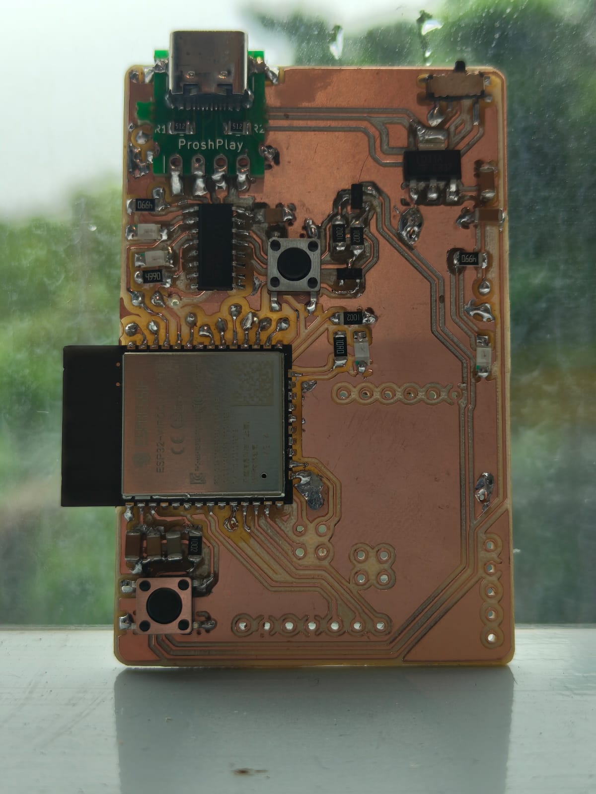
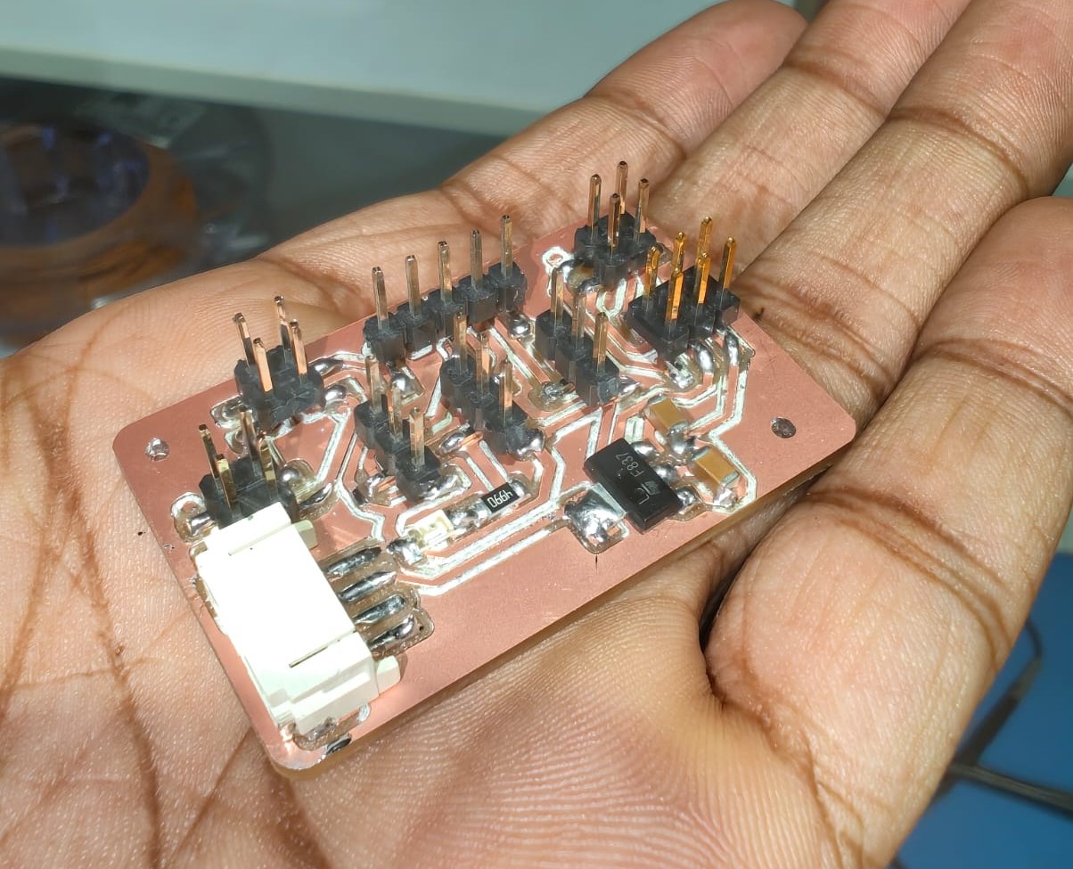
Motherboard
After completing the PCB milling I collected all the components for my mother board and soldered it.
 |
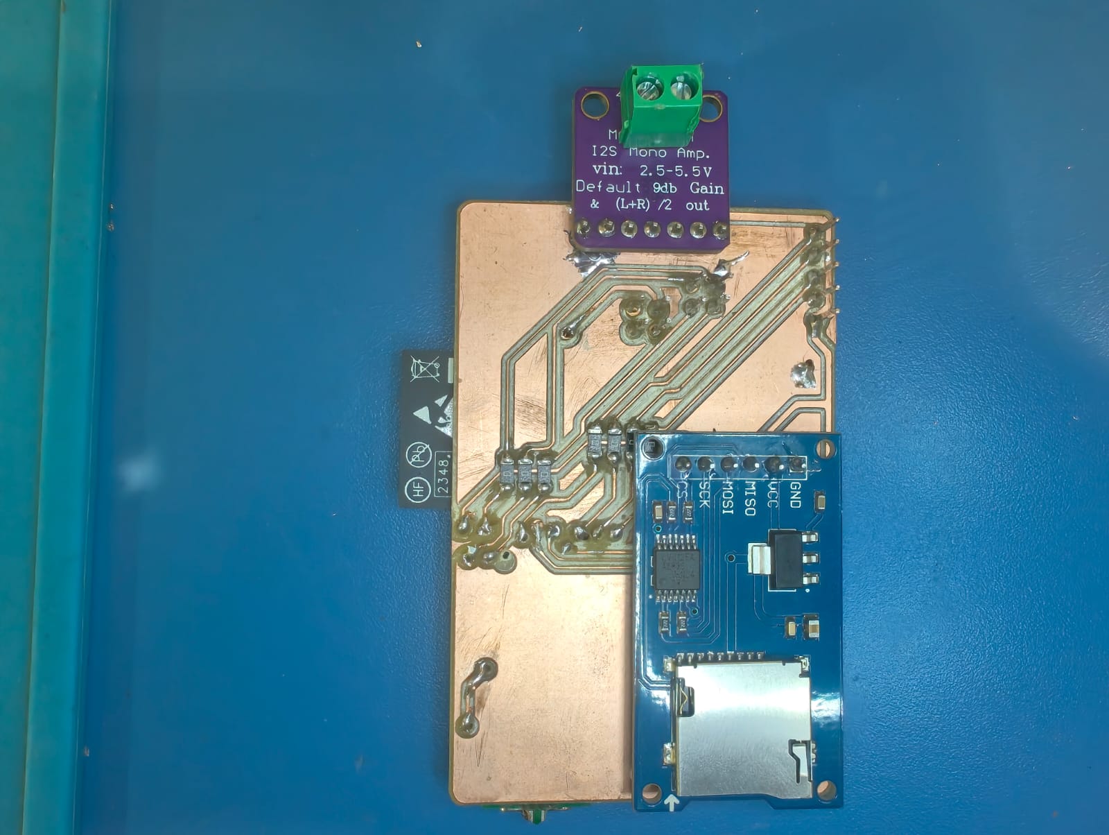 |
Similarly I milled the top board and collected the components from the inventory and soldered it.
 |
 |
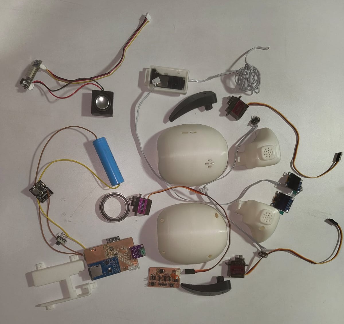
Assembly
After the fabrication of all the parts, I assembled it one by one. A lot of modules and components needed to be integrated inside the toy and it wasn't an easy task to assemble it. But fortunately all were tested earlier it was perfect and finished the assembly. It took some time but went well.
 |
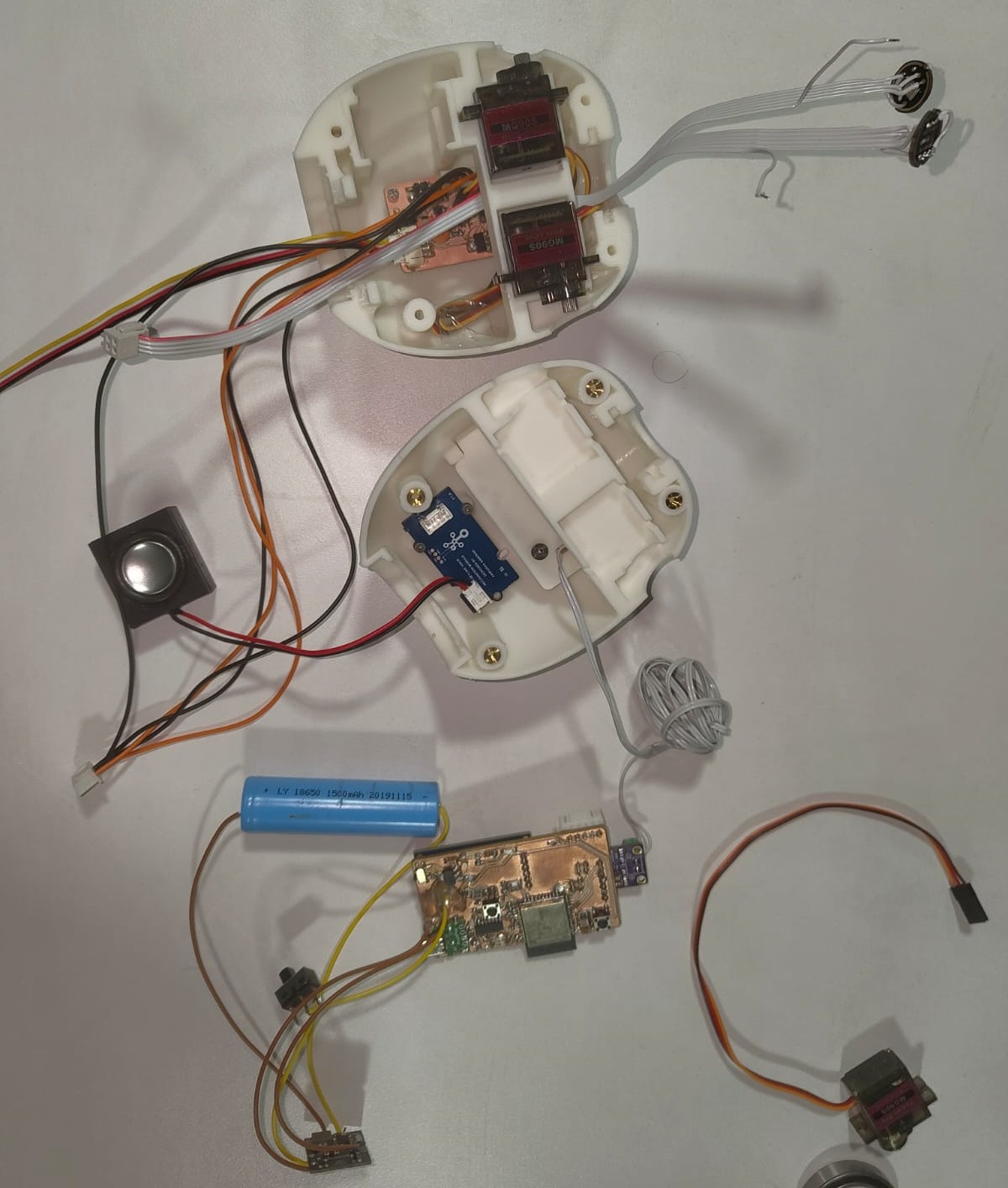 |
The actual integration looks like this,
|
|
 |
 |
This is how Chip-E looks like after the assembly.
The testing portions are added on the Testing page.
Programing
All the codes of the CHIP-E is also included in the Testing page.
All the codes can be download from the downloads section at the bottom of the page.
Systems
- Mp3 Player- The MAX98357 I2S amplifier module is connected to the ESP32, with a speaker attached to the module. I2S communication is utilized for MP3 audio playback. Additionally, an SD card module is connected to the ESP32, serving as the storage location for the MP3 files.
- Voice Recognition- The Grove Offline Voice Recognition module is connected to the ESP32. It comes with a set of preloaded voice commands, which I utilized to enable voice control functionality in the toy.
- OLED Eyes- Two OLED displays were mounted on the head of the toy to simulate eye animations.
- Moving Hands- The arms are attached to servo motors and are programmed to move in sync with the music playback.
- Capacitive Touch- A touch sensor is placed on the head to detect touch. When the toy is touched on its head, it responds by playing cute sounds and displaying animations on the OLED screens.
- Talkback- Two INMP441 MEMS microphones are mounted on each side of the toy’s head, functioning as its ears. These microphones capture the user's voice, save it in WAV format, and play it back, mimicking the behavior of a Talking Tom-style interactive toy.
- Rotating body- The toy rotates toward the direction of the sound by analyzing input from the microphones placed on its ears. By comparing the audio signals received by each microphone, it determines the source direction and adjusts its orientation accordingly.
I used different processes for this project and all are listed below,
- 3D Design – I began by designing the mechanical structure using Autodesk Fusion 360, which helped visualize and model the physical form of the project.
- Electronics Design – The custom PCB was designed in KiCAD, enabling integration of all the necessary electronic components.
- Digital Fabrication – I employed both additive manufacturing (3D printing) for complex parts and subtractive manufacturing methods such as CNC milling and laser cutting for structural and functional components
- Embedded Programming – Microcontroller-based programming was used to control hardware features and create interactive functionalities.
- Integration and Assembly – Finally, all components—mechanical, electronic, and software—were integrated into a functional prototype.
All these processes were mentioned in above part of this documentation.
What questions were answered?
- Who is going to use this?
- Will it play the audio?
- Can it be controlled by voice?
- What will be displayed on the display?
The kids of age group of 2 to 5 are the users of this product. The aim of this product is to reduce the amount of screen time of kids.
Yes, The toy can play audio from SD card. Also it can act as a talking toy.
Yes it can recognise the voice commands and for that I use a Groove offline voice recognition module. Curently I am using the preloaded commands.
Eyes are animated on the display.
What worked and what didn't?
I intended to integrate a wide range of features into the toy — including a music player, voice talkback similar to Talking Tom, arm movements synced with music, sound direction-based rotation, and responsive animations and sounds triggered by a capacitive touch sensor on its head. Most importantly, I aimed to make the toy voice-controlled. Technically, I was able to implement all these features successfully. However, due to time constraints, I couldn’t merge all the individual codes into a single unified system. As a result, while each feature works perfectly on its own, they currently do not function together in an integrated manner.
The project should be evaluated by the following points,
- Is it suitable for kids?
- Will it play audio from SD crad?
- Will it playback the users sound?
- Is it voice controlled?
Finally the out put is shown here,
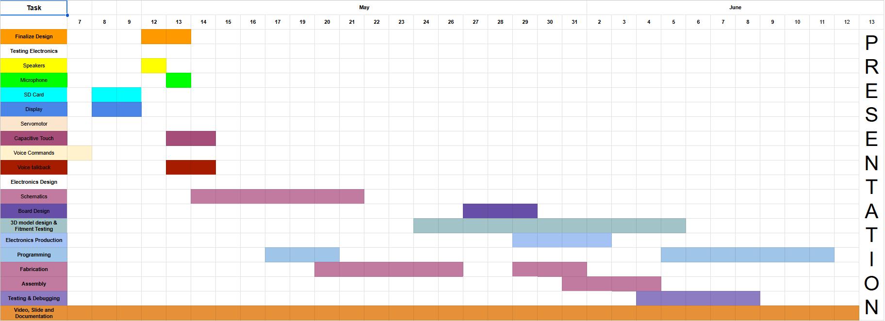
Schedule
To ensure smooth progress and effective time management, I created a detailed schedule for my project. This schedule outlined all the key stages and tasks involved, allowing me to approach each phase with clarity and purpose. By planning ahead, I was able to allocate sufficient time for design, development, testing, and final adjustments. It helped me avoid last-minute rushes and ensured that every important aspect of the project was given proper attention.
Sticking to a structured timeline also allowed me to track my progress and stay motivated as I completed each milestone. It provided a clear roadmap, making it easier to identify priorities and manage unexpected challenges without derailing the entire workflow. Overall, having a well-planned schedule was one of the most effective strategies I used to stay organized, focused, and on track throughout the development of my project.
At the initial stage of the project, I thoroughly tested each feature to ensure they functioned as intended. All the results and observations from these tests were carefully recorded and documented on the testing page. This helped me keep track of the system's performance, identify any issues early on, and make necessary improvements efficiently.
Conclusion
As the creator of CHIP-E, this project allowed me to explore and integrate multiple technologies like voice recognition, servo control, and audio playback using the ESP32. Despite challenges, I was able to bring together various features into a functional, interactive robot that responds to voice, touch, and expresses emotions—making the process both technically enriching and creatively fulfilling.
Downloads
Fab Academy © 2025 by Revisankar S is licensed under CC BY-NC-SA 4.0![]()
![]()
![]()
![]()