Electronics production
Objectives for Week 7
- make and test a microcontroller development board that you designed
- characterize the design rules for your in-house PCB production process
- submit a PCB design to a board house
Individual Assignment
Group Assignment:
Group Assignment
In this week's group assignment we tested the minimum trace width and minimum spacing between each tracks which we can obtain from our PCB milling machine and the results are shown below.
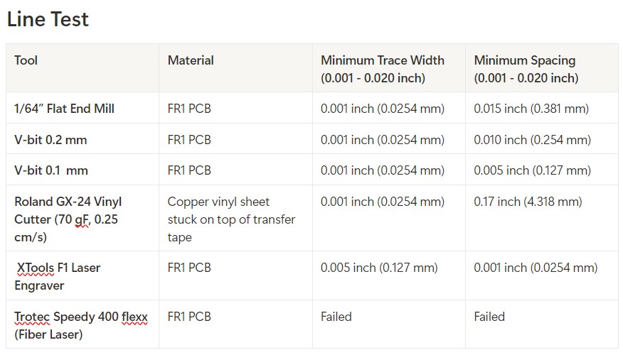
Group assignment link.
Printed Circuit Board(PCB)
A PCB (Printed Circuit Board) is a board that connects electronic components using copper tracks instead of wires. It provides a strong and compact structure for circuits, making electronic devices smaller and more reliable.
In this week I produced the board which I was designed in the Electronics design week. It was a single sided PCB and I produced it in the Roland Modela MDX-20 milling machine available in our lab.
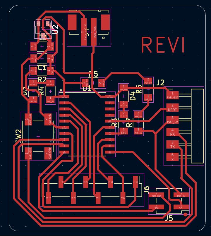
Roland Modela MDX-20
The Roland Modela MDX-20 is a compact CNC milling machine used for PCB prototyping, engraving, and 3D milling. It can mill materials like copper-clad boards, plastic, and wax with high precision.
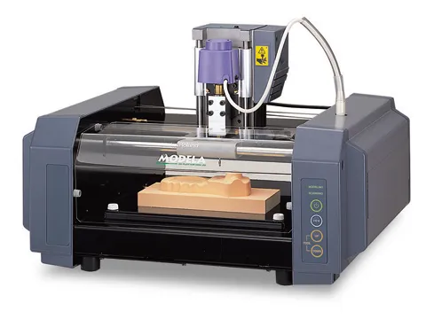
|
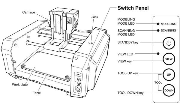
|
Gerber2PNG
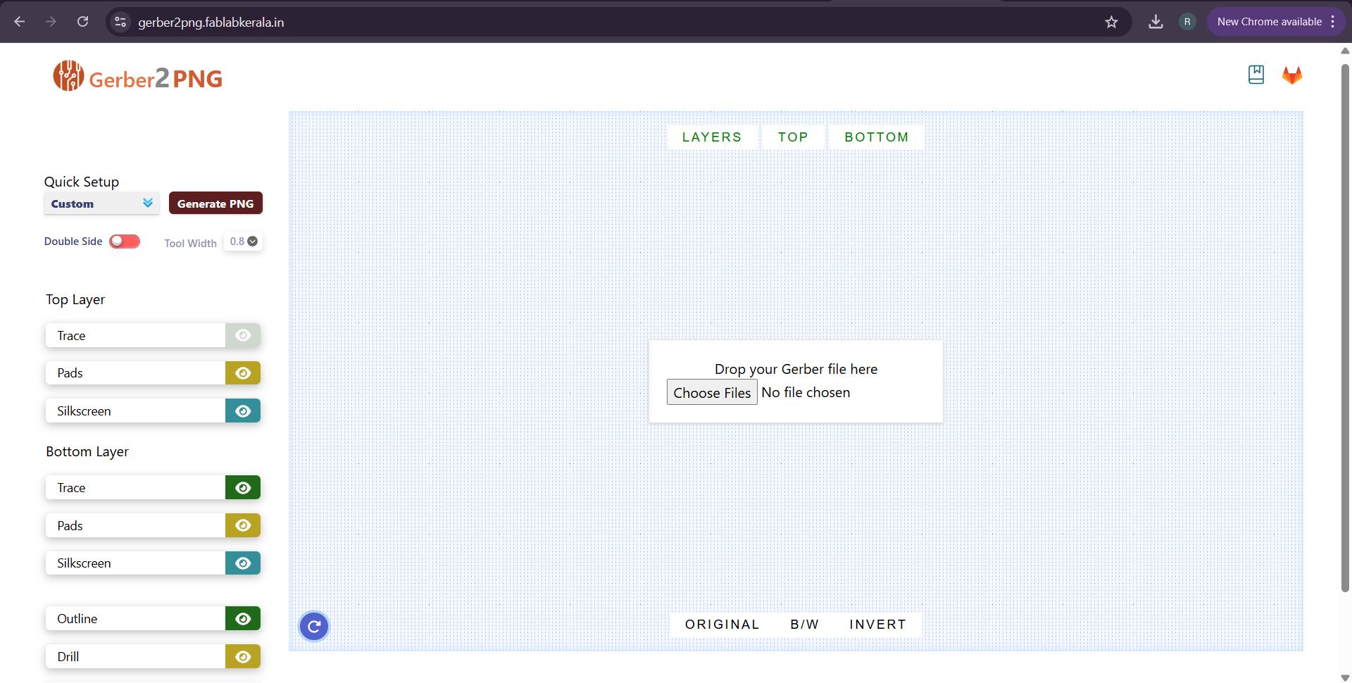
In our lab we use mods for CAM. For producing the PCB the input file for mods should be either in .svg or .png. Eventhough both are supported the .svg file is coverted into .png file in mods before CAM. Some time there should occur some erros in .svg file conversion. So here in our lab we always use .png file for production.
The Gerber2PNG was a software made here in Super Fablab kerala and it is a great tool for converting the gerber file to .png. Our software develpoer Muhammed Midlaj N created this software.
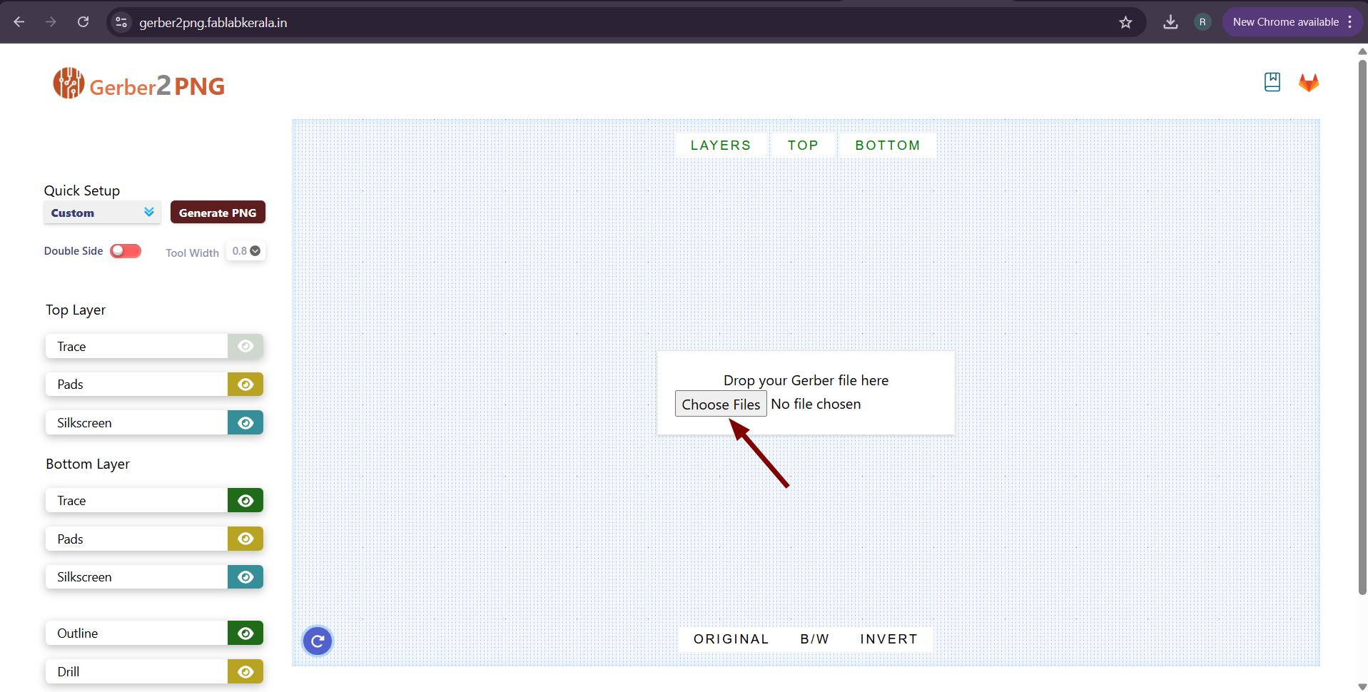
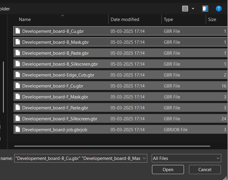
Import the gerber files by clicking Choose Files and select all the gerber files exported from the KiCAD.
 |
 |
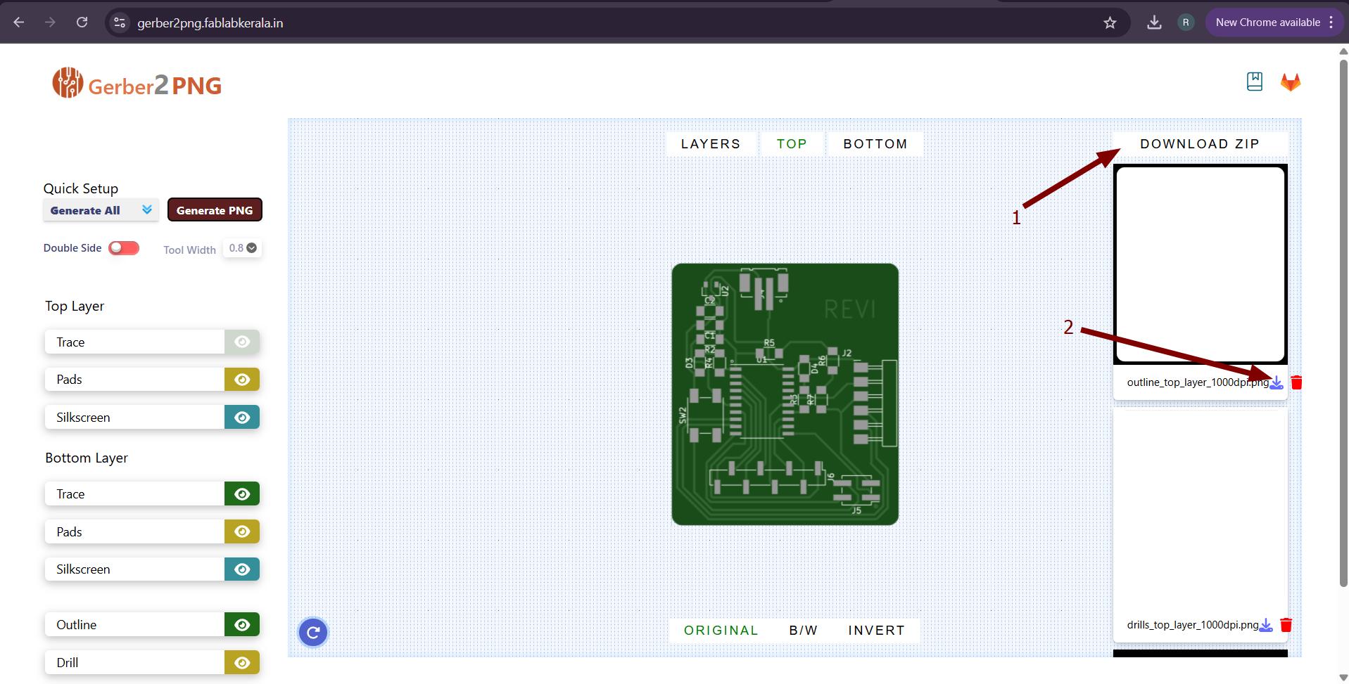
The PCB imported in the Gerber2PNG and shown there. In Quick Setup Select Generate all and click Generate PNG.
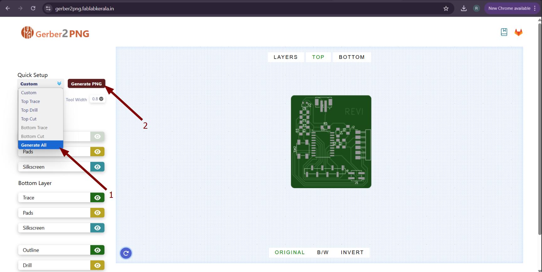
Then the gerber was converted into PNG with outline, drills (if any), and traces. We can download all as .zip file or can download individually as well.
PCB Production
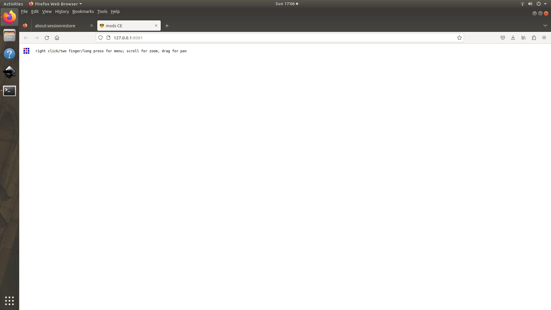
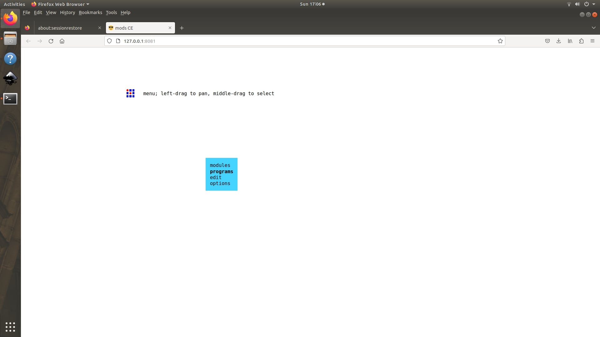
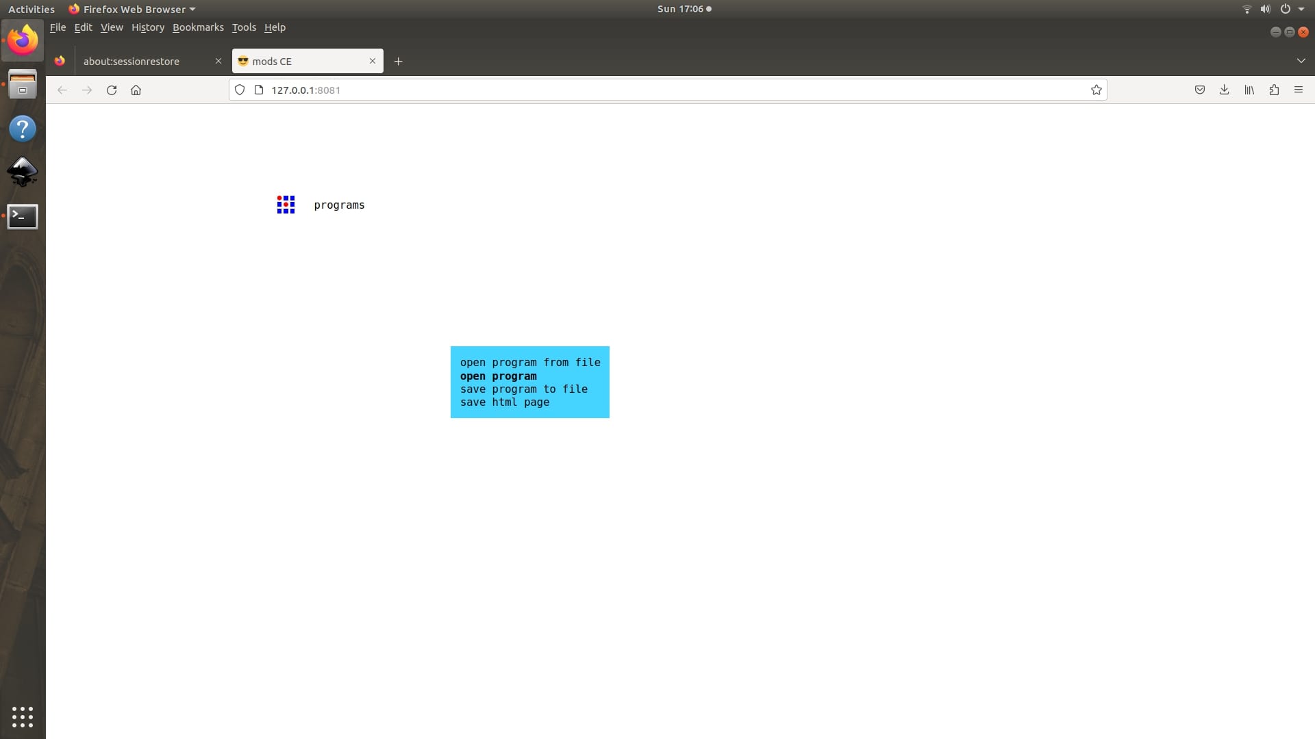
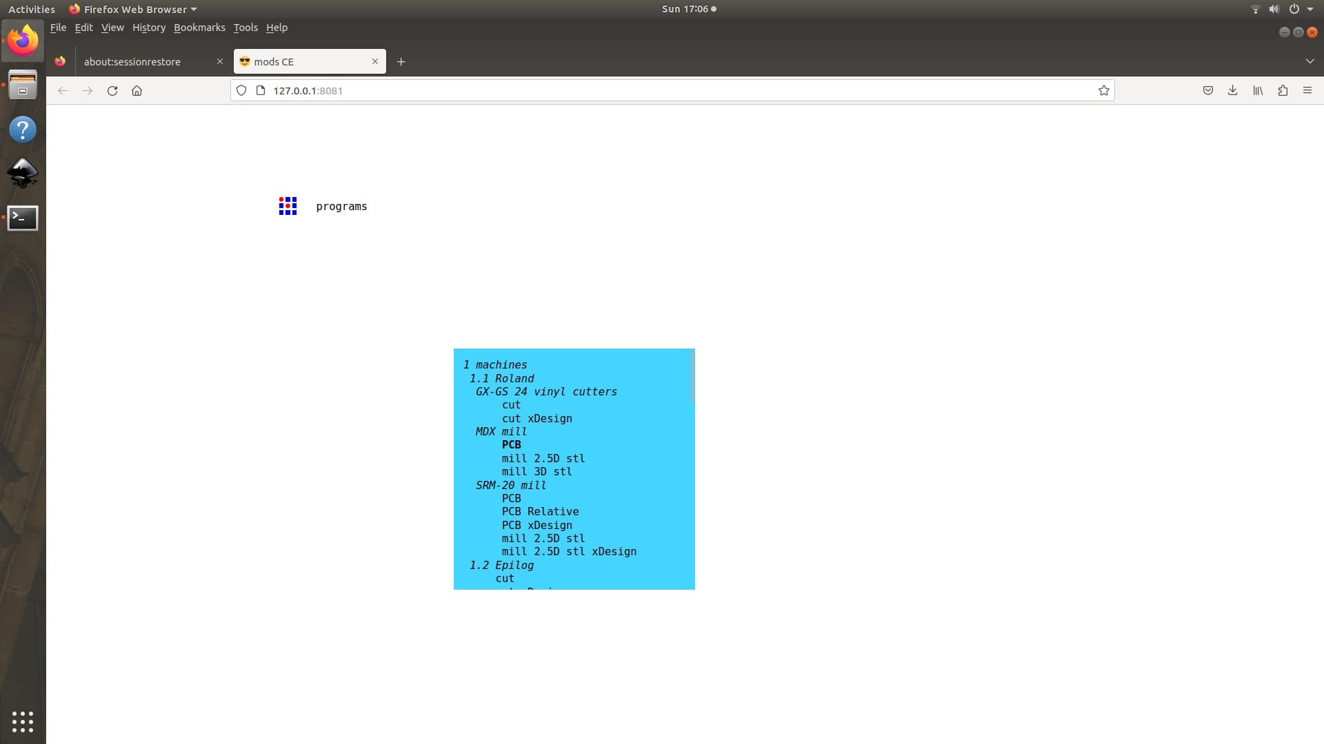
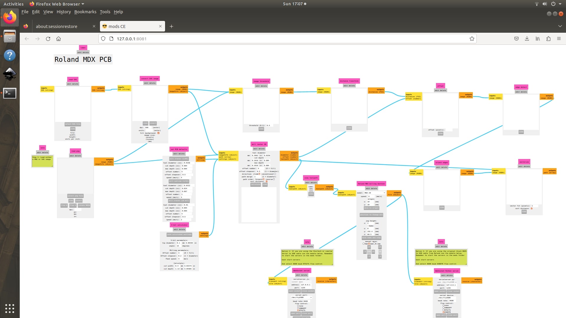
The mods software was used for CAM. To open CAM for roland, Right click on initial screen of mods → Select Programs → Open Programs → MDX mill → PCB
|
|
|
|
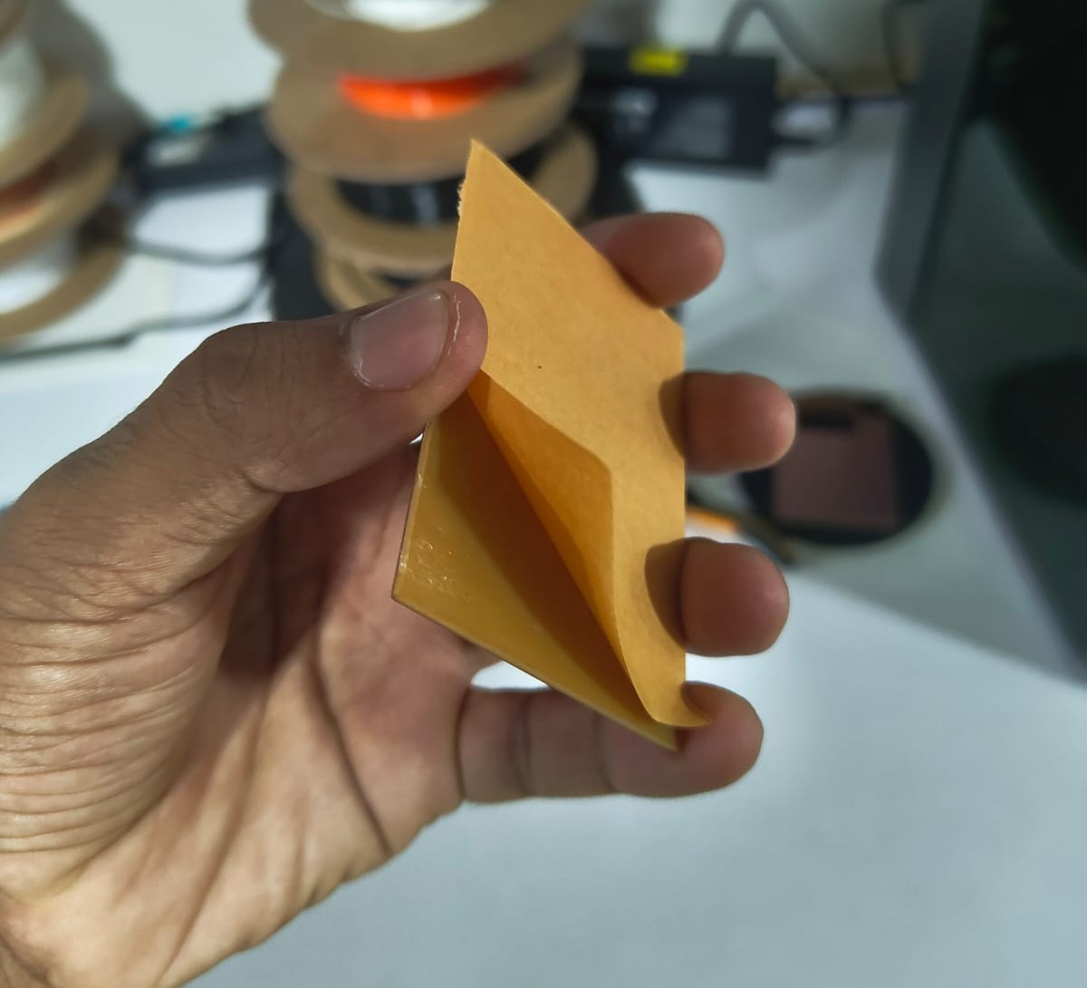
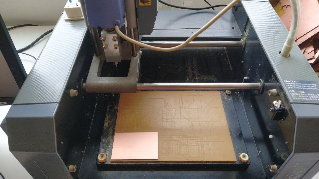
The machine's bed is cleaned and I fixed the copper clad board using the double sided tape.
 |
 |
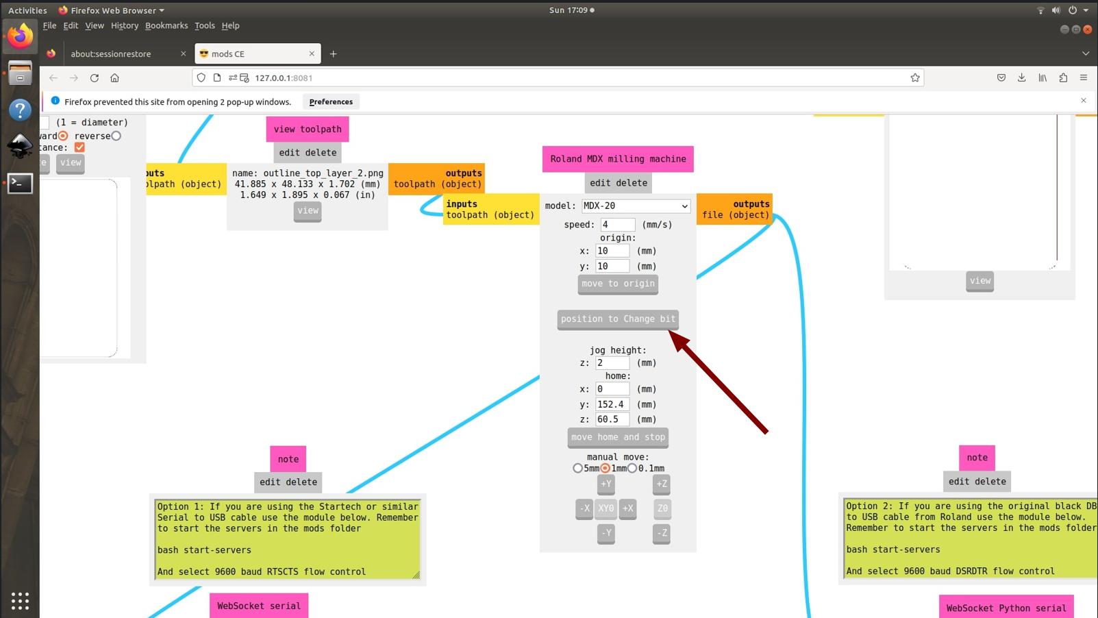
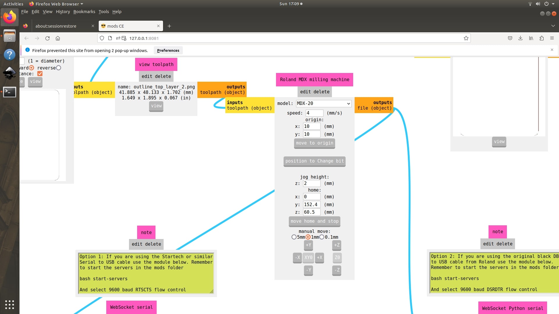
To change the tool, used the Position to change bit option so that the machine moves to a position so that the tool can be changed easily.
 |
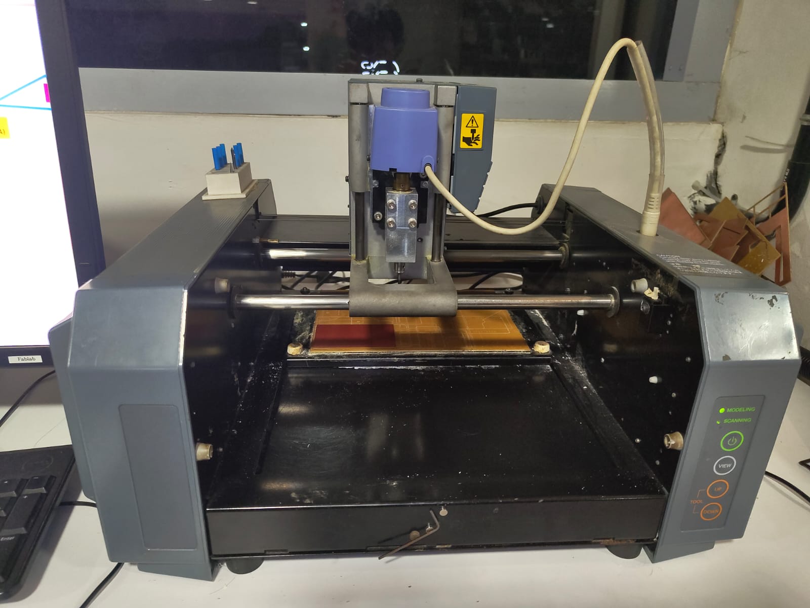 |
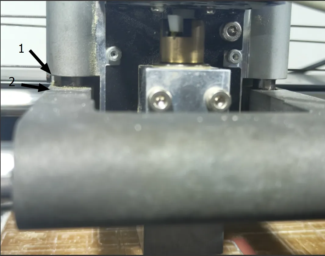
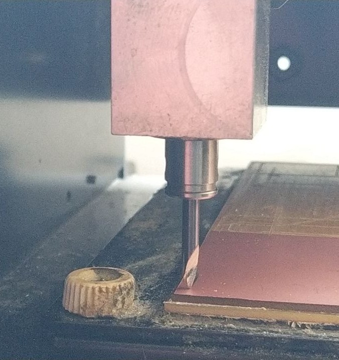
Initially the traces were needed to be milled. I inserted the 0.2mm 60 degree v bit to cut the traces. The bit is inserted maximum inside and tightned one of the grub screw. Then I moved the machine 10mm in X direction and 6mm in Y direction. To set the Z offset I moved the Z axis downwards using the down button of the machine untill the gap between the marked 1 and 2 positions is about a thickness of a finger. Loosen the grub screw and touch the tool to the top surface of copper clad board and tighten both the grub screws.
|
|
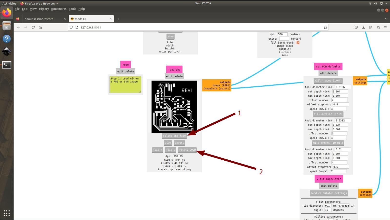
Imported the traces png to the mods using the select png file option(1). The board dimensions were shown there and there is an option to rotate the image(2) if needed. While milling I forgot to check the dimension of the board and fortuntely the board got inside it.
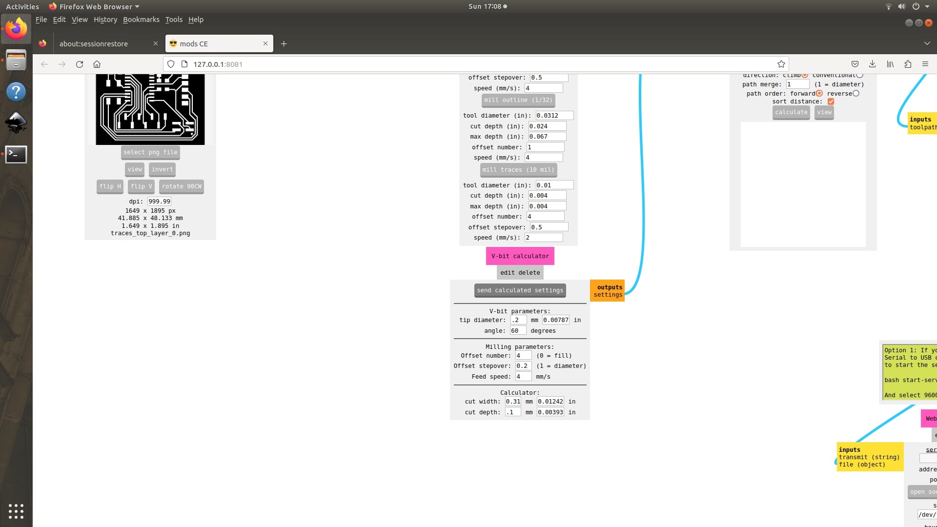
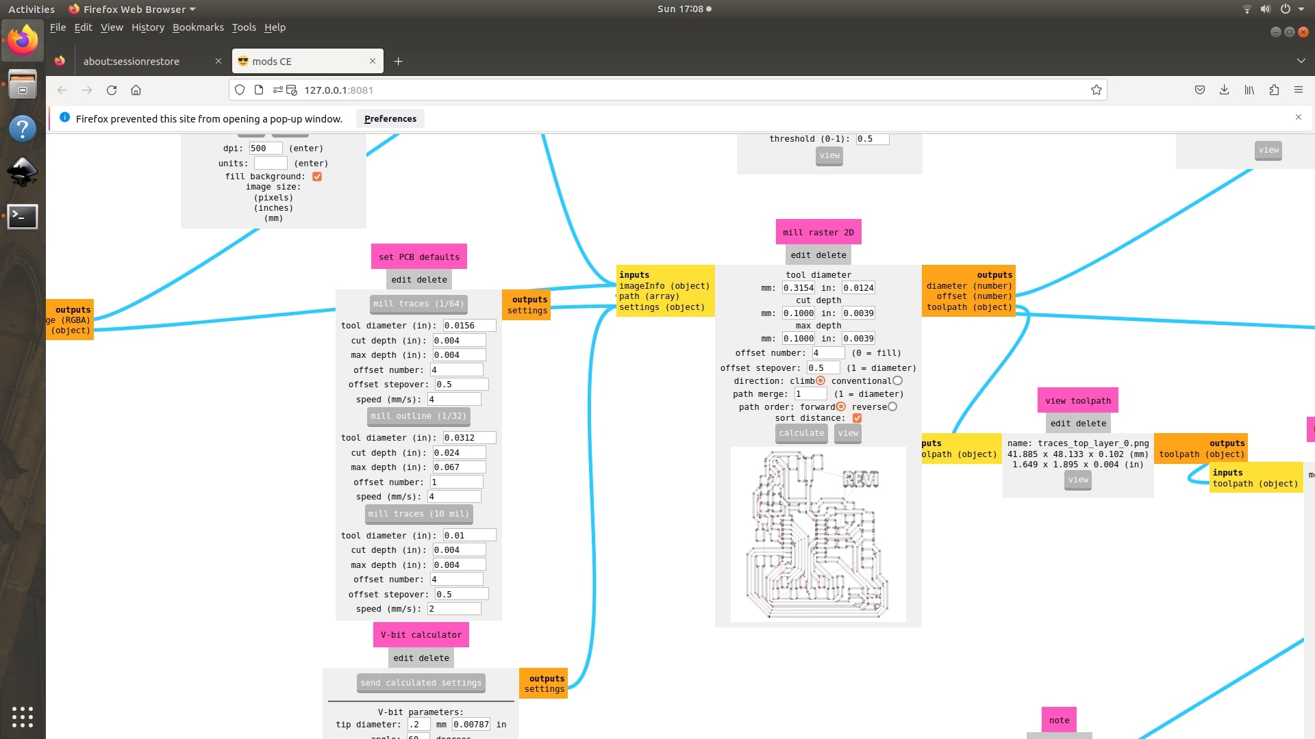
As I used the V bit for milling the parameters for the bit needed to be enter into the mods. I used a vit bit of 0.2mm tip diameter and 60degree angle. The copper clad have a thickness of 0.07mm and for safety I gave 0.1mm so if any height difference occer while fixing the board on to the machine's bed can be overcomed. After giving all the parameters select send calculated settings.
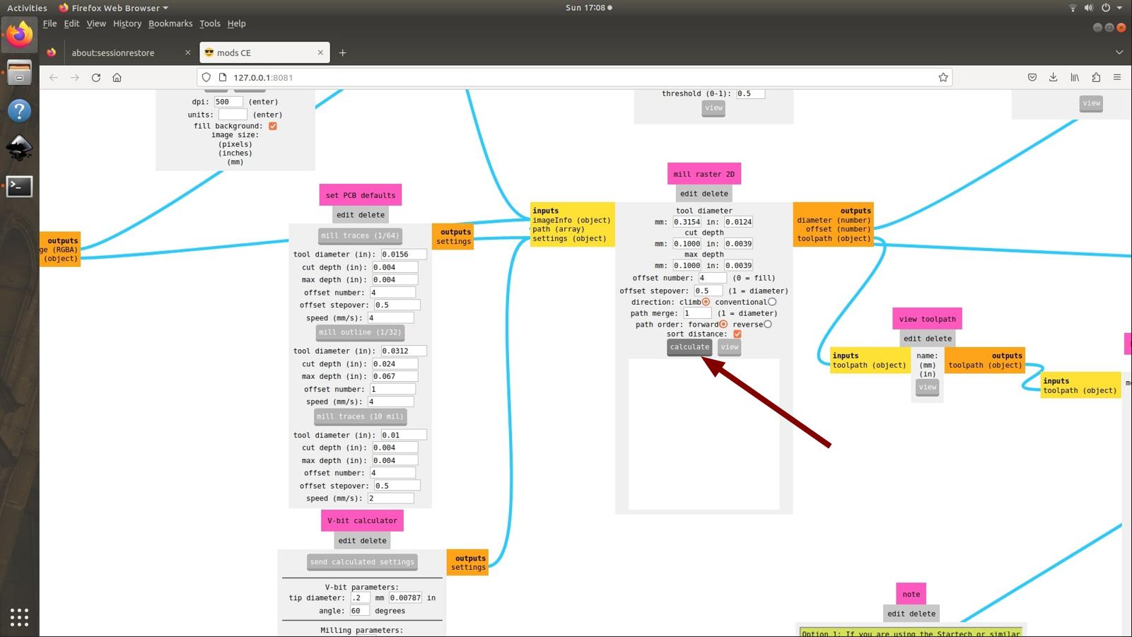
These parameters are send to mill raster 2D and press calculate there. The toop path is generated and for verifying use the view button next to calculate.
 |
 |
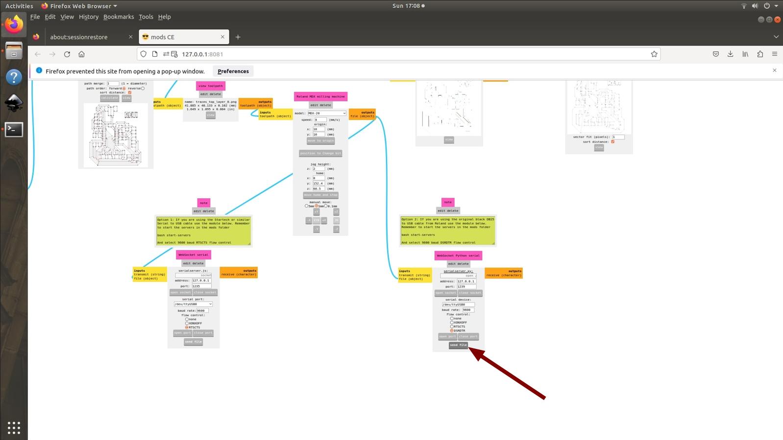
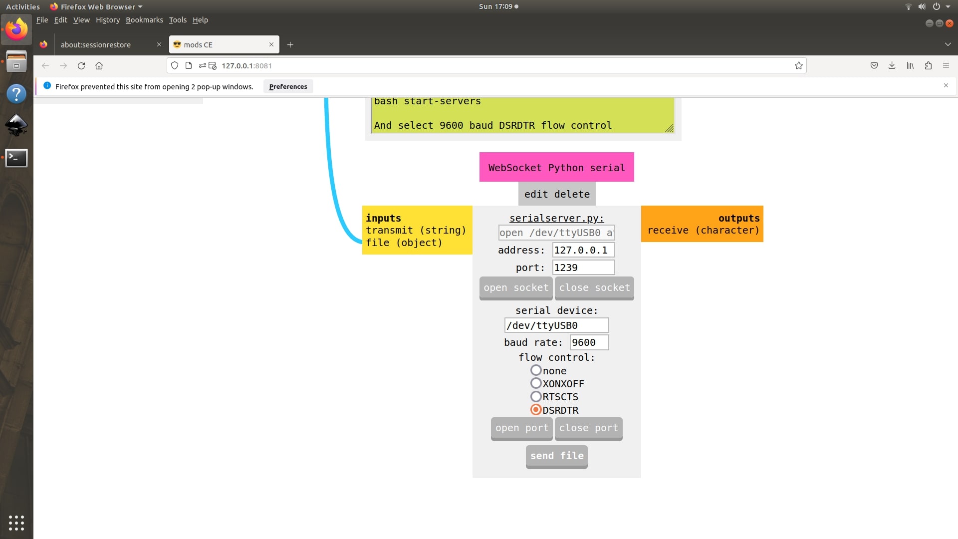
Verified everything was correct and send the file to the machine using send file option. and the machine starts milling the traces.
The traces were milled successfully. The chips were cleaned using the vaccum cleaner.
 |
After milling the traces successfully, I needed to mill the outline of my board. The outline is milled using the 0.8mm tool. So I needed to change the tool. I followed the steps to insert the V tool for changing the tool. In the mods I selected the position to change bit option and loosen the grub screw and removed the V bit and inserted the 0.8mm bit. same like the V bit I touched the tool on to the top surface of the copper cladding and tighten the grub screws. Then I imported the Outline png on to mods. Selected the mill outline option in set PCB defaults.
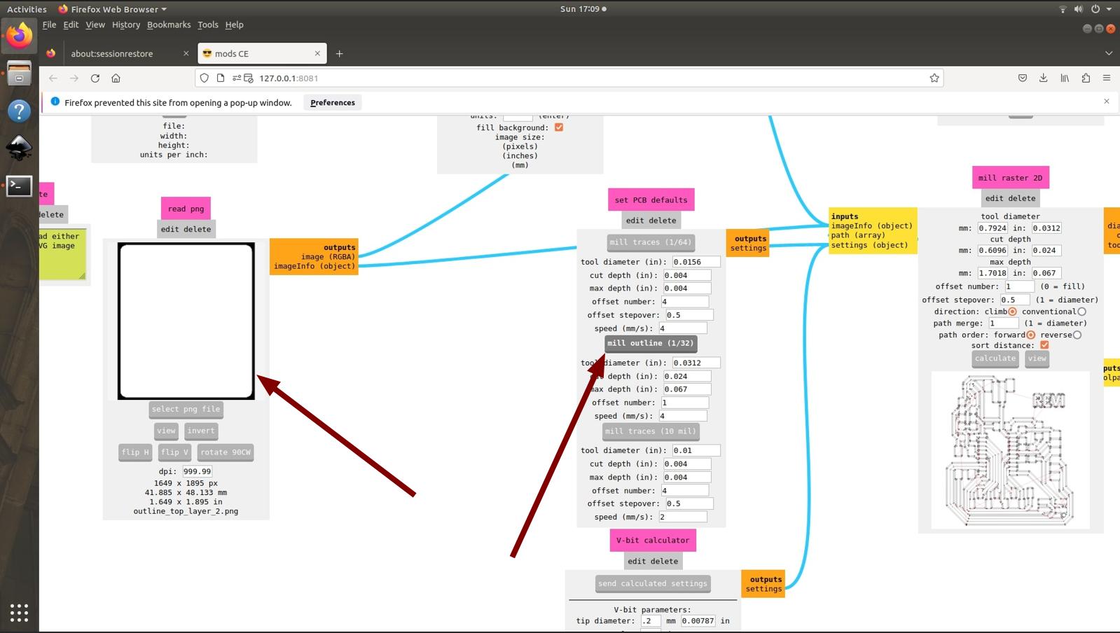
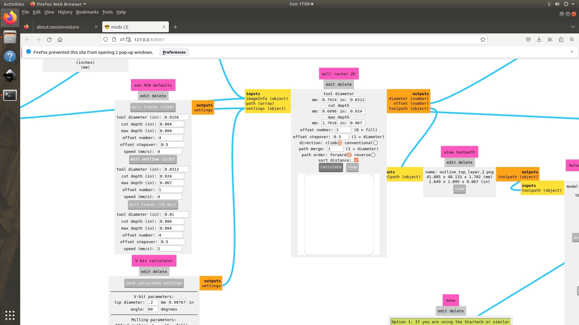
Click calculate to generate tool path and click send file to send file to machine.
 |
 |
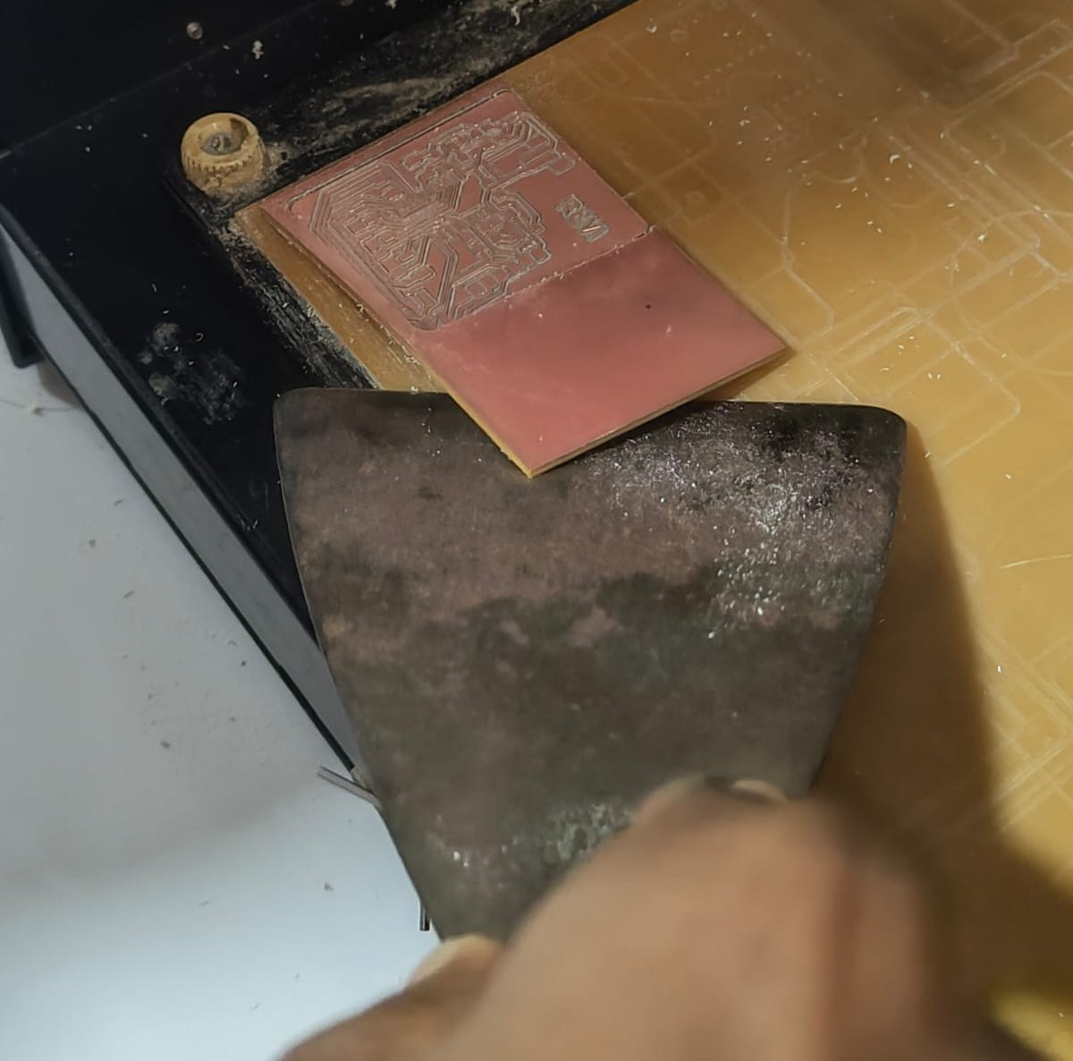
The machine starts milling the outline of the board. Ater completing the milling the chips are cleaned using the vacuum cleaner and the board is taken from the machine's bed using a scraper.
 |
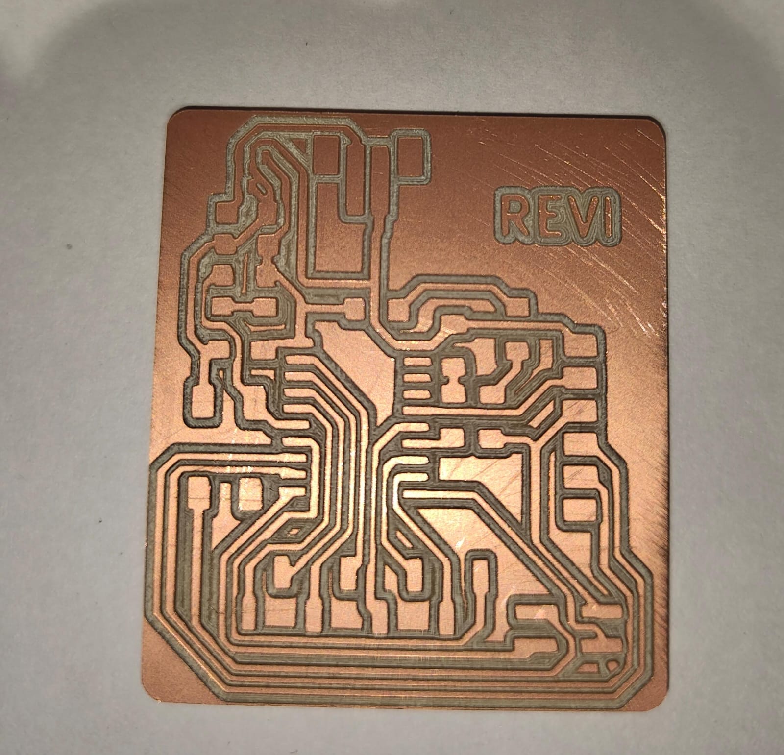
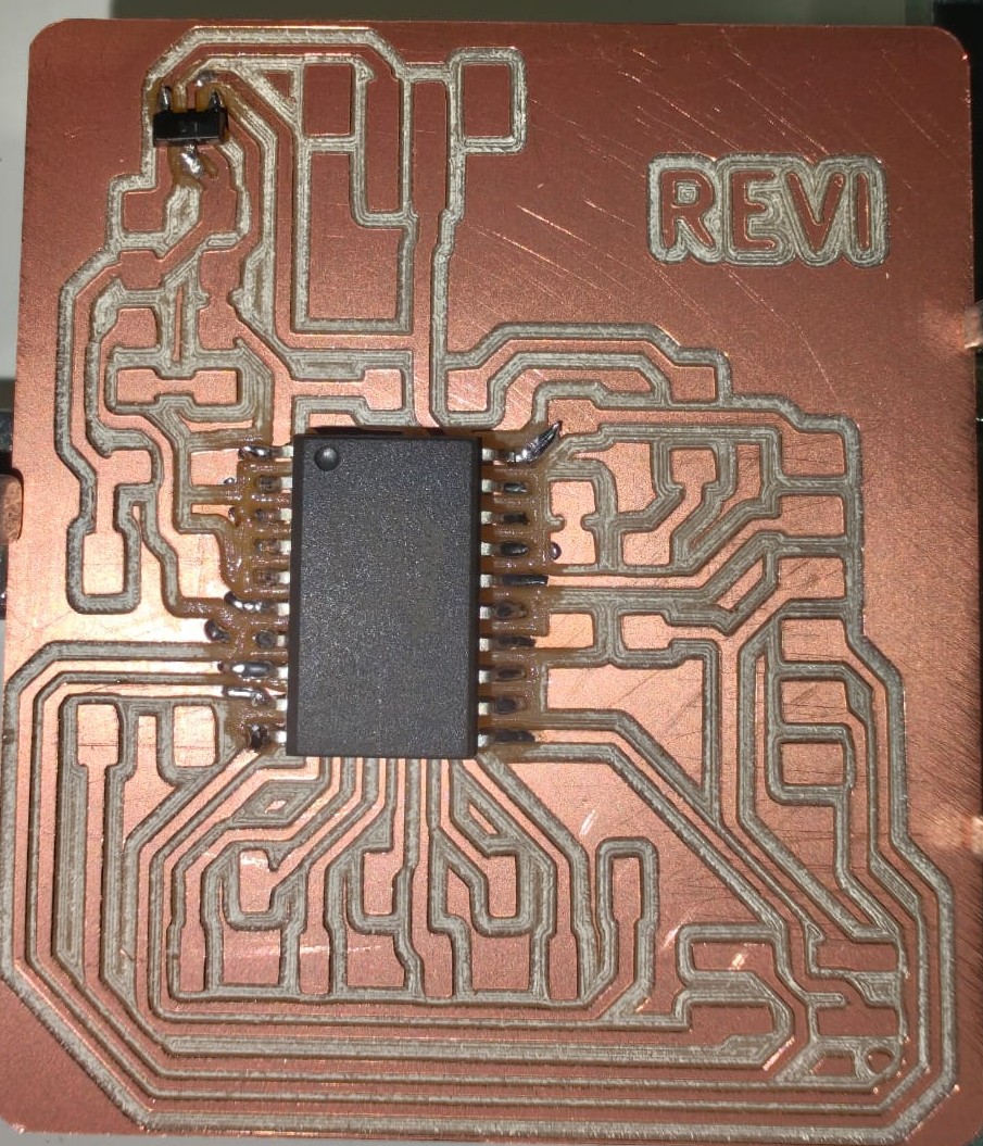
The board looks like this.
FabStash
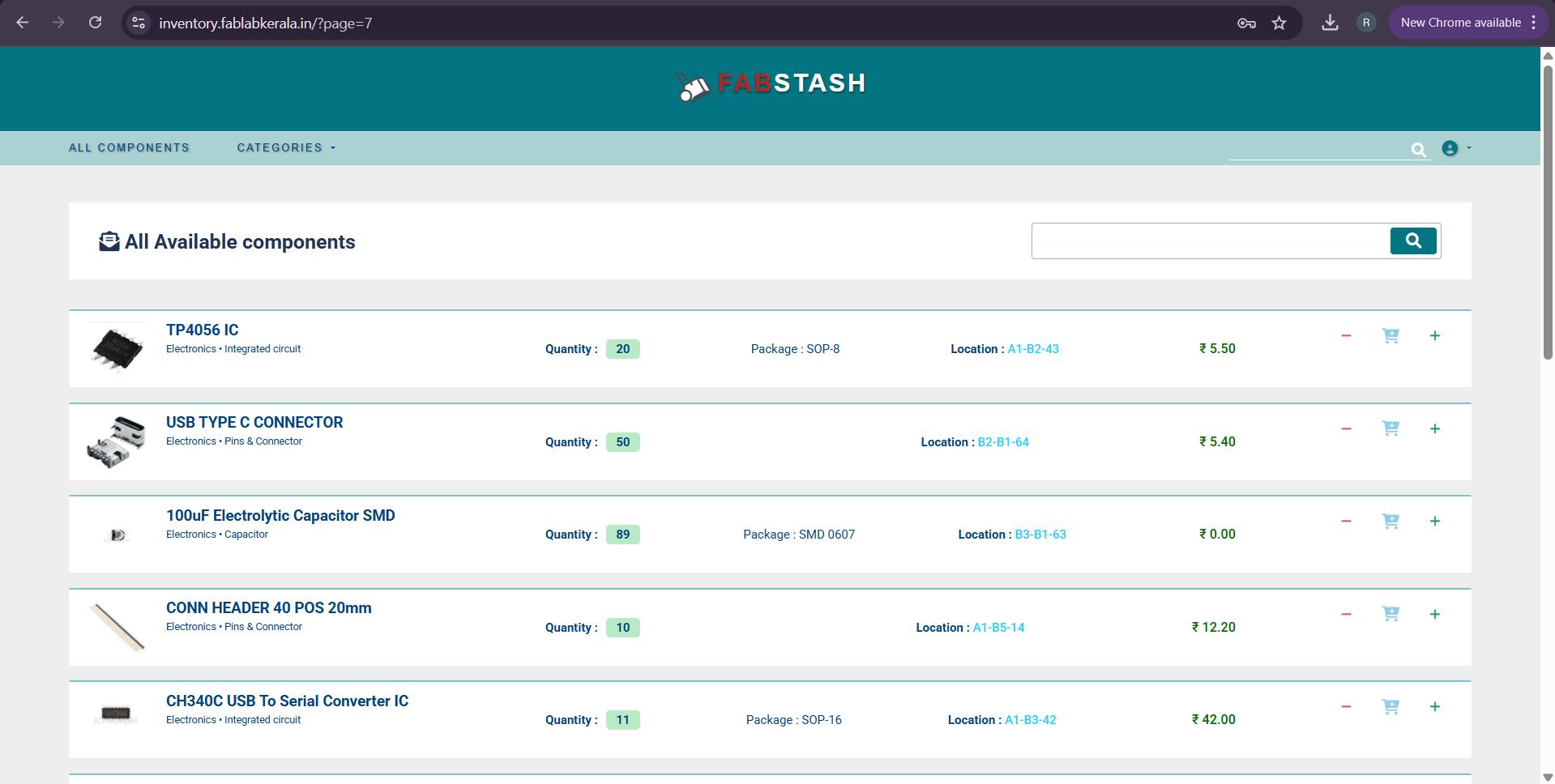
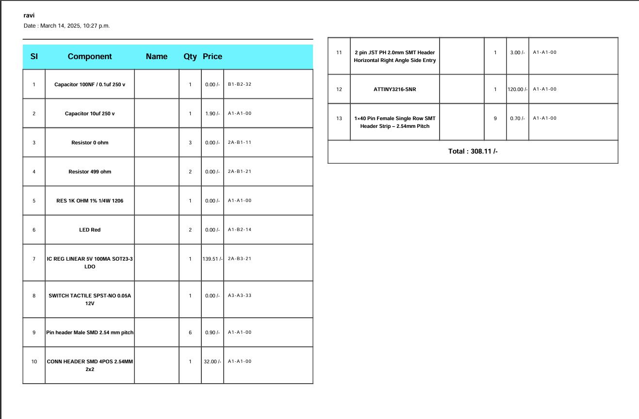
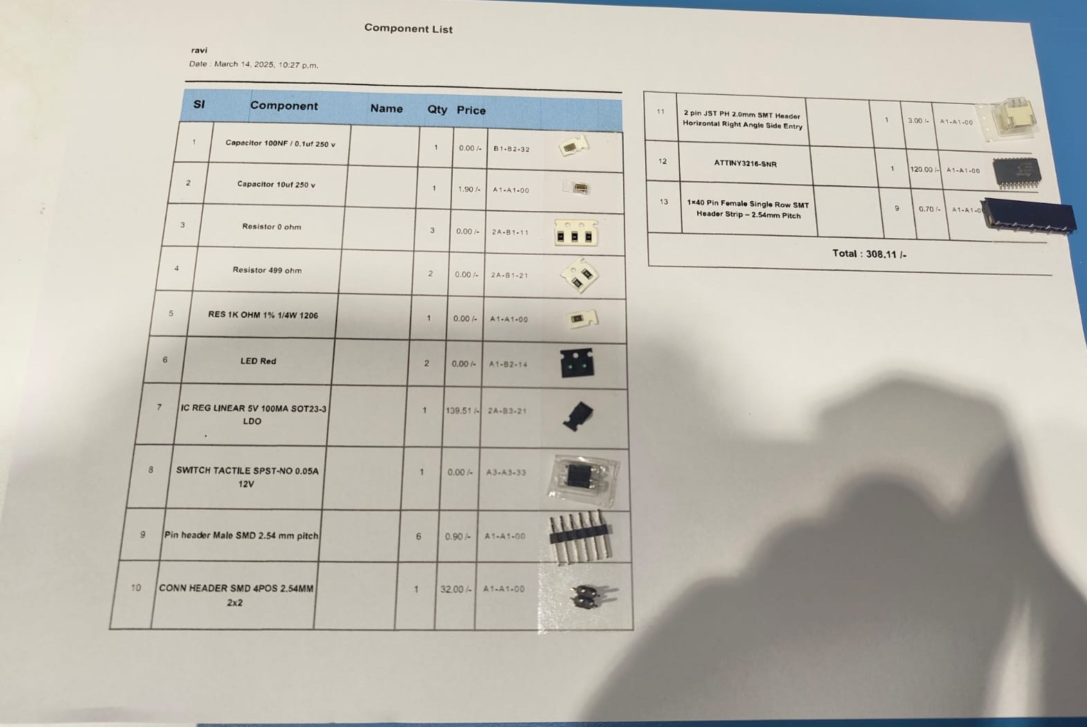
FabStash is the inventory app we used here in Super Fablab Kerala. The components needed for soldering the PCB was requested through this inventory app. After aprooving I printed that component list and taken the components from the inventory and pasted it on the printed component list for identifying it easily while soldering.
 |
 |
Soldering
Soldering is a process of joining metal components by melting a filler metal (solder) to create a secure electrical and mechanical bond. It’s commonly used in electronics to connect wires and components on circuit boards.
Components used
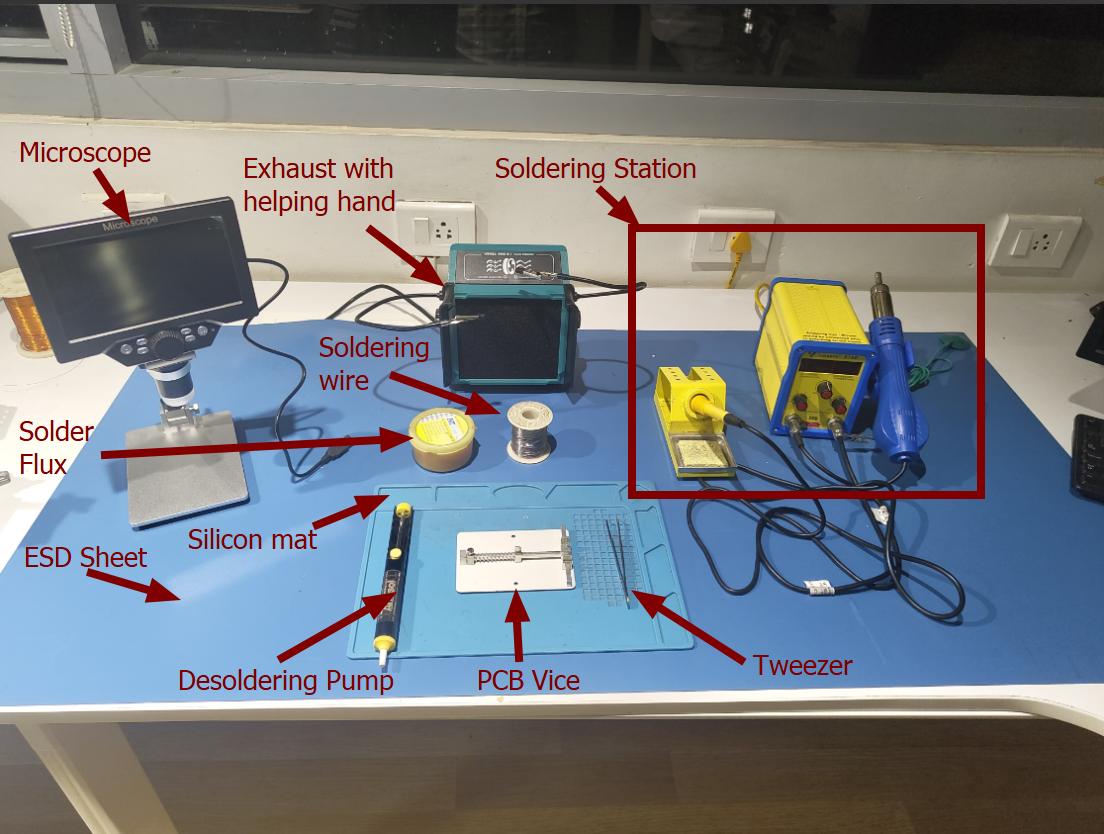
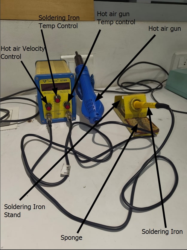
- Soldering Station
- Soldering Iron- Used for soldering and desoldering the components.
- Power Controller- Used to adjust the temperature of the soldering iron.
- Soldering iron stand- Stand to place the soldering iron when not in use.
- Sponge cleaner- Used to clean the tip of the soldering iron.
- Hot air gun- Used for soldering and desoldering the components.
- Soldering flux- Soldering flux is a chemical substance used in soldering to clean and remove oxidation from metal surfaces, helping the solder flow smoothly and create strong, reliable connections between electronic components.
- Tweezer- A tweezer is a small hand tool with two pointed arms used for precisely picking up and handling tiny components, such as resistors, capacitors, or wires, that are too small to manipulate with your fingers. They're essential for delicate work like assembling or repairing circuit boards.
- Desoldering Pump- A desoldering pump, also known as a solder sucker, is a tool used in electronics to remove solder from circuit boards. After heating the solder with a soldering iron, the pump creates suction to quickly suck up the molten solder, allowing components to be detached or cleaned up. It's useful for fixing mistakes or replacing components.
- Silicon Mat- A silicone mat is a flexible, heat-resistant surface used in electronics workstations. It provides a non-slip area for soldering, assembling, and repairing electronic components, protecting the underlying surface from heat, solder spills, and static electricity. Many silicone mats also have printed grids and compartments for organizing small parts and tools, making them practical for detailed work.
- PCB vice- A PCB vise is to hold the PCB in place while soldering.
- Microscope- Microscopes are used in soldering to work with tiny components, especially in Surface Mount Technology (SMT). They help in precise soldering, inspecting joints, and repairing circuits by providing clear magnified views. This reduces errors, improves quality, and minimizes eye strain. Stereo and digital microscopes are commonly used for these tasks.
- ESD Protection Sheet- An ESD sheet protects electronic components from static electricity, which can damage them. It provides a grounded surface to safely remove static charges, making it essential for soldering circuit boards and delicate parts.
- Exhaust- An exhaust system in soldering is used to remove harmful fumes and smoke produced by molten solder and flux. It improves air quality, prevents inhalation of toxic substances, and ensures a safer working environment.
Soldering wire- Soldering wire is a thin metal wire used to join electronic components by melting it with a soldering iron, forming a conductive bond between parts on a circuit board.
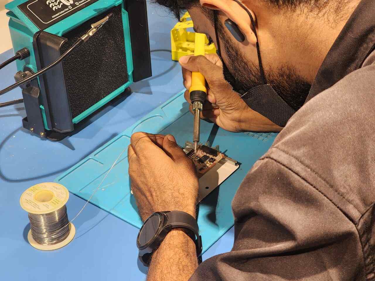
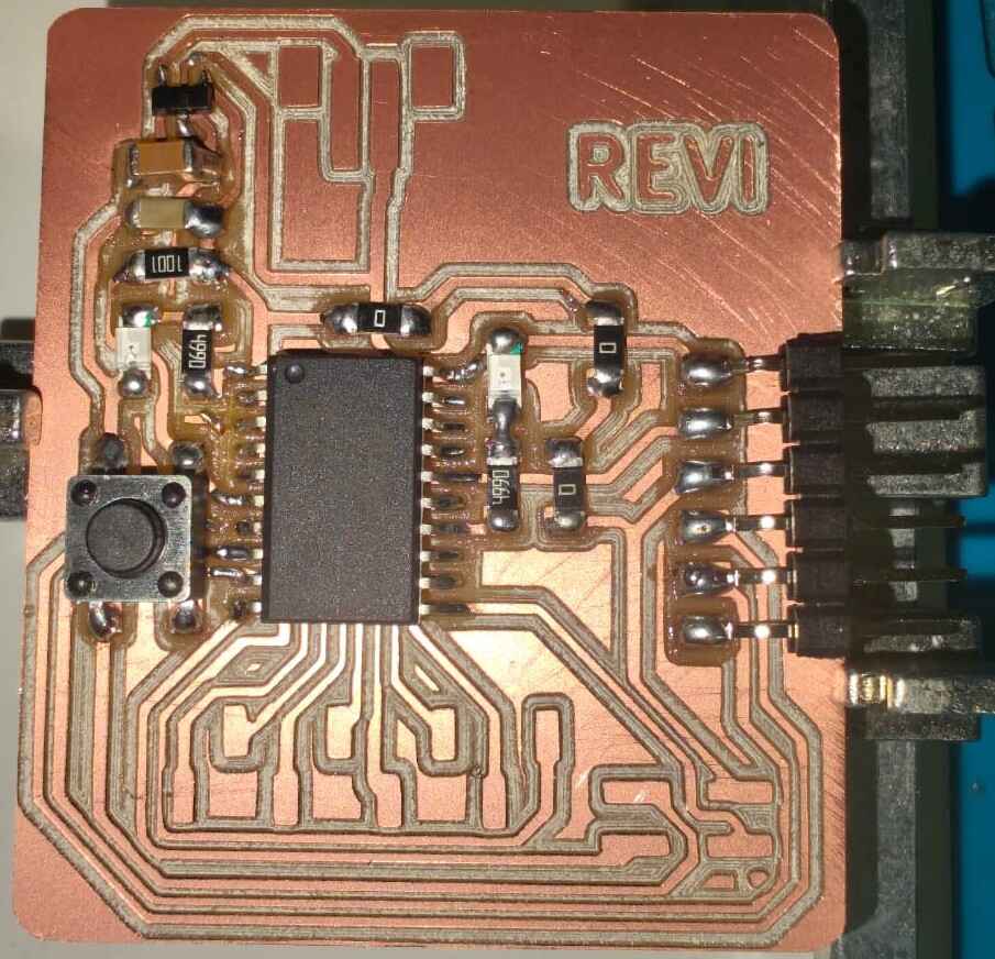
Initially I took the ATtiny3216 microcontroller and solder it on the PCB. And all other components were soldered according to their size so that it can be soldered easily. It took almost one hour 30 minutes to solder the board but I noticed thet it wasn't too difficult.
 |
 |
 |
 |
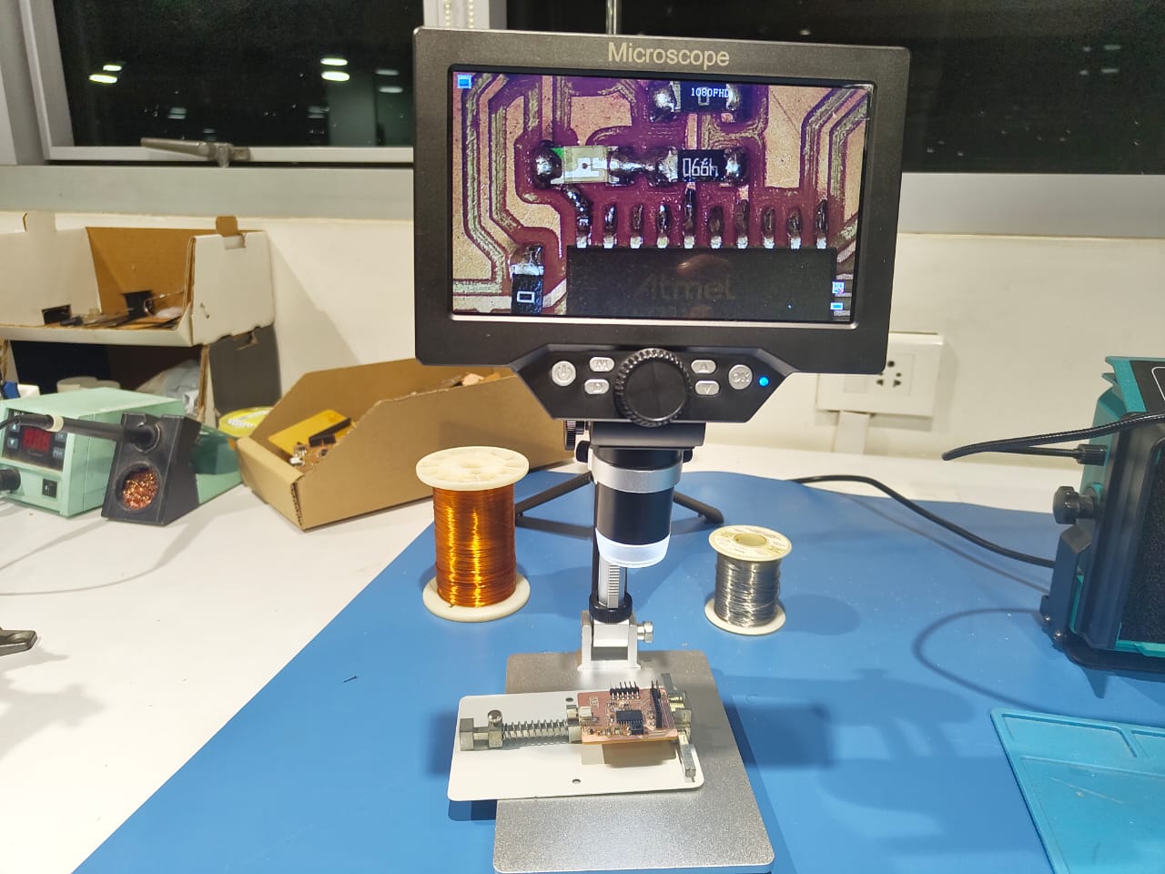
After soldering the board I used the microscope to inspect the board whether the soldering were correct. And also verified any traces were connected while soldering. Fortunately the soldering was correct and no traces were connected.
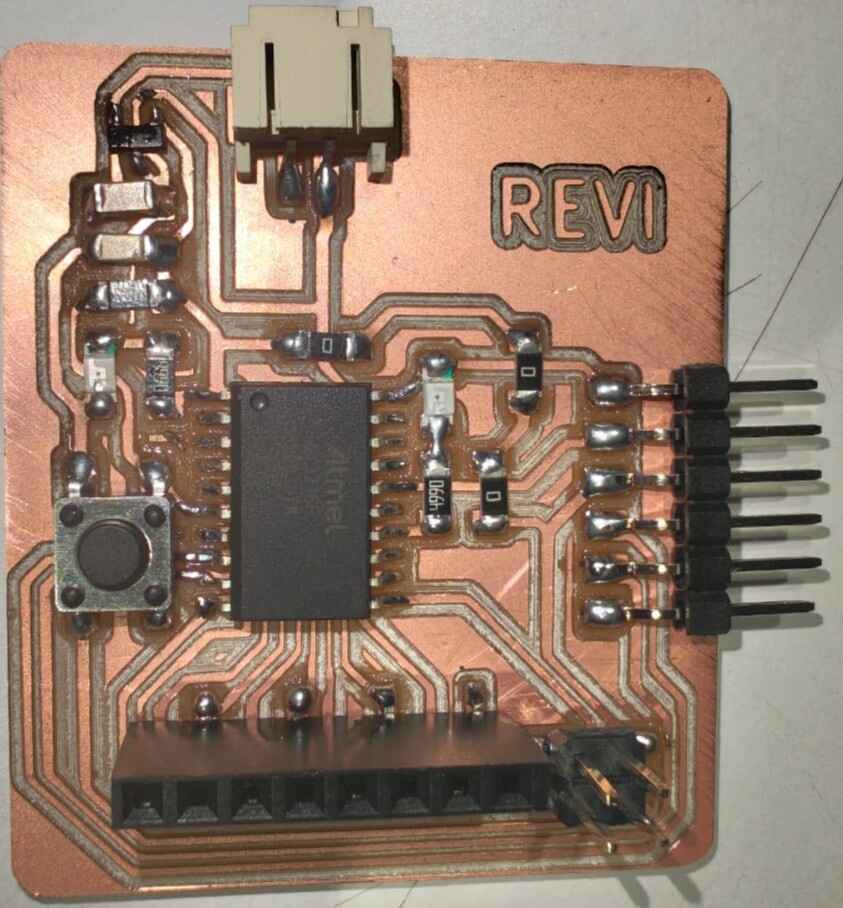
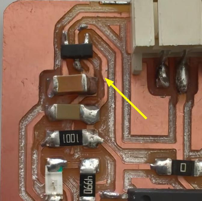
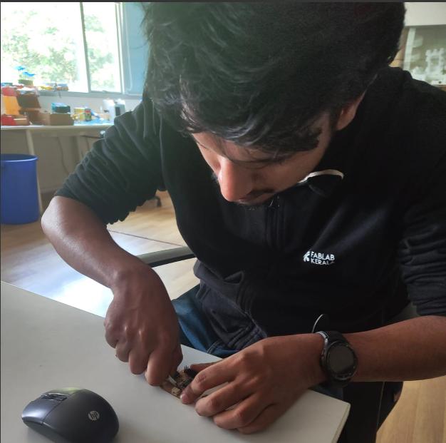
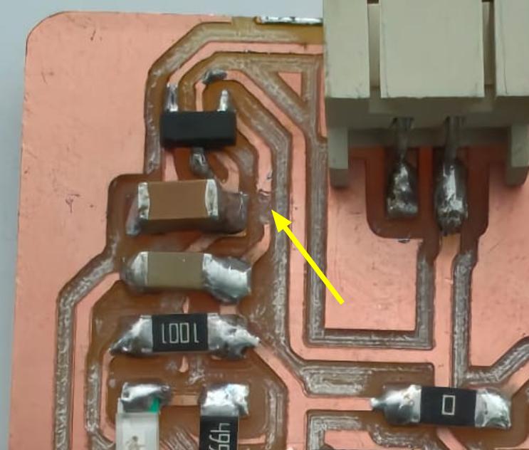
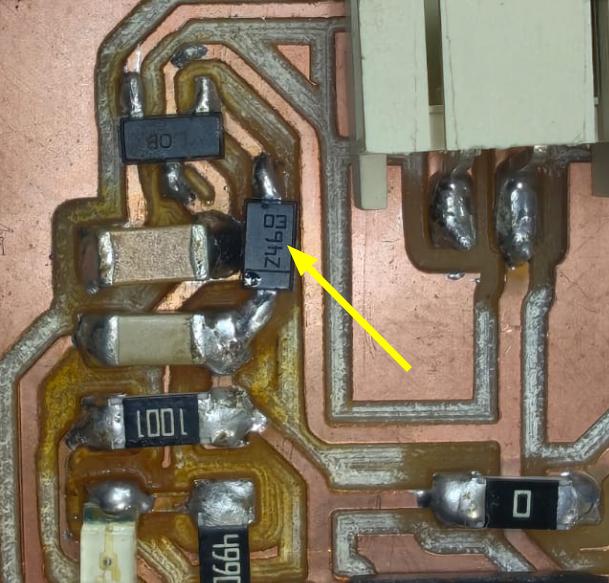
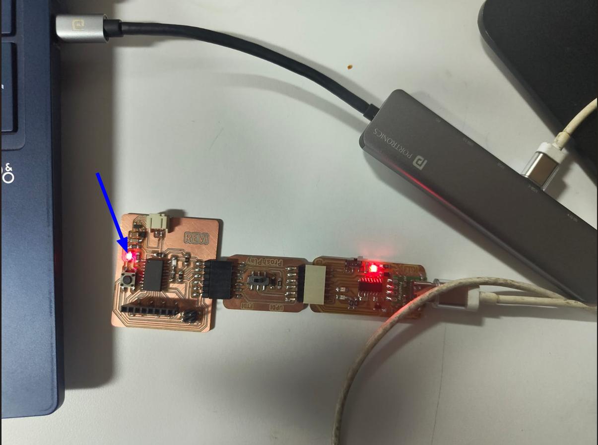
After the installation, for testing I connected the PCB to my PC with the programmer and USB hub. The USB hub is to protect the USB port of my PC whether any short was present on the board. After connecting it I noticed that the power LED is not turned ON. I inspected the board closely and noticed that the Liner regulator is heating up. I asked help with my instructor Saheen and he debugged the board and told me that a 5V is coming into the output of the linear regulator and that's why it is heating. He cut one of the traces and told me to add a schottky diode of 150mA.
|
|
|
|
After the modification the power Led turns ON.
Pin Out Diagram
Programming
I used Arduino IDE for programming the micro controller. I used ChatGPT for adding MegaTinyCore to Arduino IDE. megaTinyCore is an Arduino core that allows you to program modern ATtiny microcontrollers (like ATtiny3216) using the Arduino IDE. It supports UPDI programming, multiple clock speeds, and built-in hardware features like UART, SPI, and I2C. It makes ATtiny chips work like an Arduino, enabling easy coding and uploading.
ChatGPT promt: Setup Arduino IDE for ATtiny3216.
Setup Arduino IDE for ATtiny3216
Step 1: Install Arduino IDE
Download and install the Arduino IDE from arduino.cc.
Step 2: Add the Board Package URL
Go to File > Preferences and paste the following URL into the "Additional Boards Manager URLs" field:
https://github.com/SpenceKonde/megaTinyCore/releases/download/v2.6.1/package_MCUdude_megatinycore_index.json
Step 3: Install megaTinyCore
Open Tools > Board > Boards Manager, search for megaTinyCore by Spence Konde, and click Install.
Step 4: Select ATtiny3216 Board
Go to Tools > Board and choose ATtiny3216/1606/1607/3216/3217, then select ATtiny3216.
Step 5: Configure Board Settings
- Chip: ATtiny3216
- Clock: 20 MHz internal
- BOD: 2.6V
- Programmer: jtag2updi (megaTinyCore)
- Port: Select the correct COM port
Step 6: Burn Bootloader
Go to Tools > Burn Bootloader to apply the correct fuse settings.
Step 7: Upload Sketch
Connect your ATtiny3216 using a UPDI programmer and click Upload in the Arduino IDE.
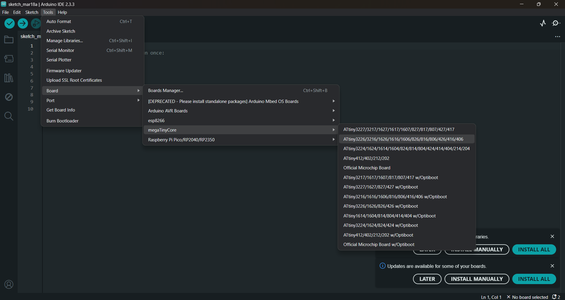
After installing the megaTinyCore to arduino IDE, select the Attiny3216 borad from Tools→ Board →megaTinyCore → Attiny3216.
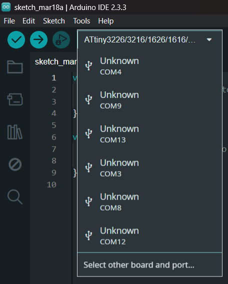
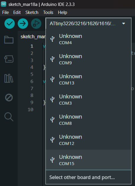
Then I selected the COM port of my PC where I connected the microcontroller. To check whether which COM port I connected, Just drop down the COM port tab and plug the microcontroller. A new COM port will appear there and select that one.
 |
 |
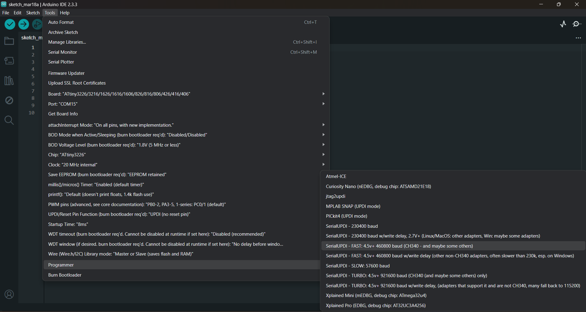
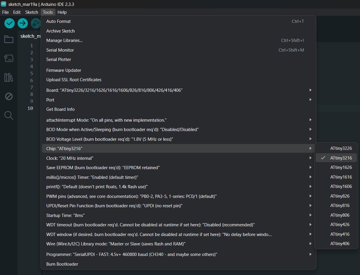
I selected the programmer after that. Tools→Programmer→SerialUPDI-Fast:4.5v+ 460800 baud (CH340- and maybe some others)
Burned the bootloader by Tools→Burn Bootloader.
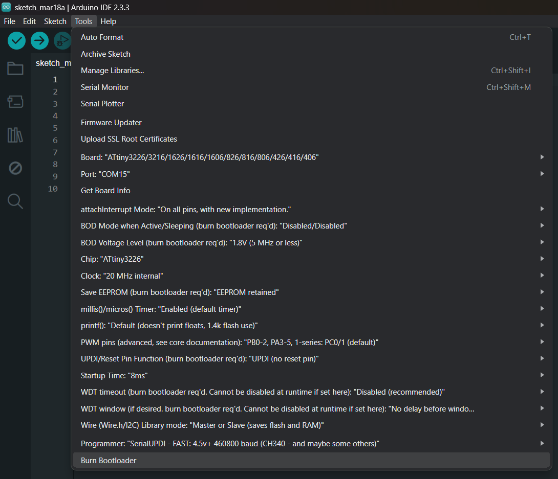
Select ATtiny3216 from Tools→Chip→ATtiny3216.
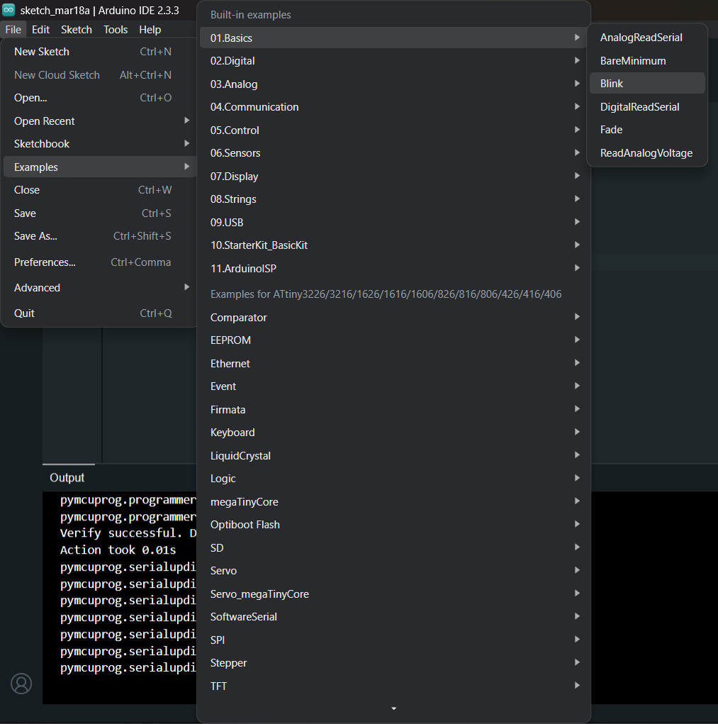
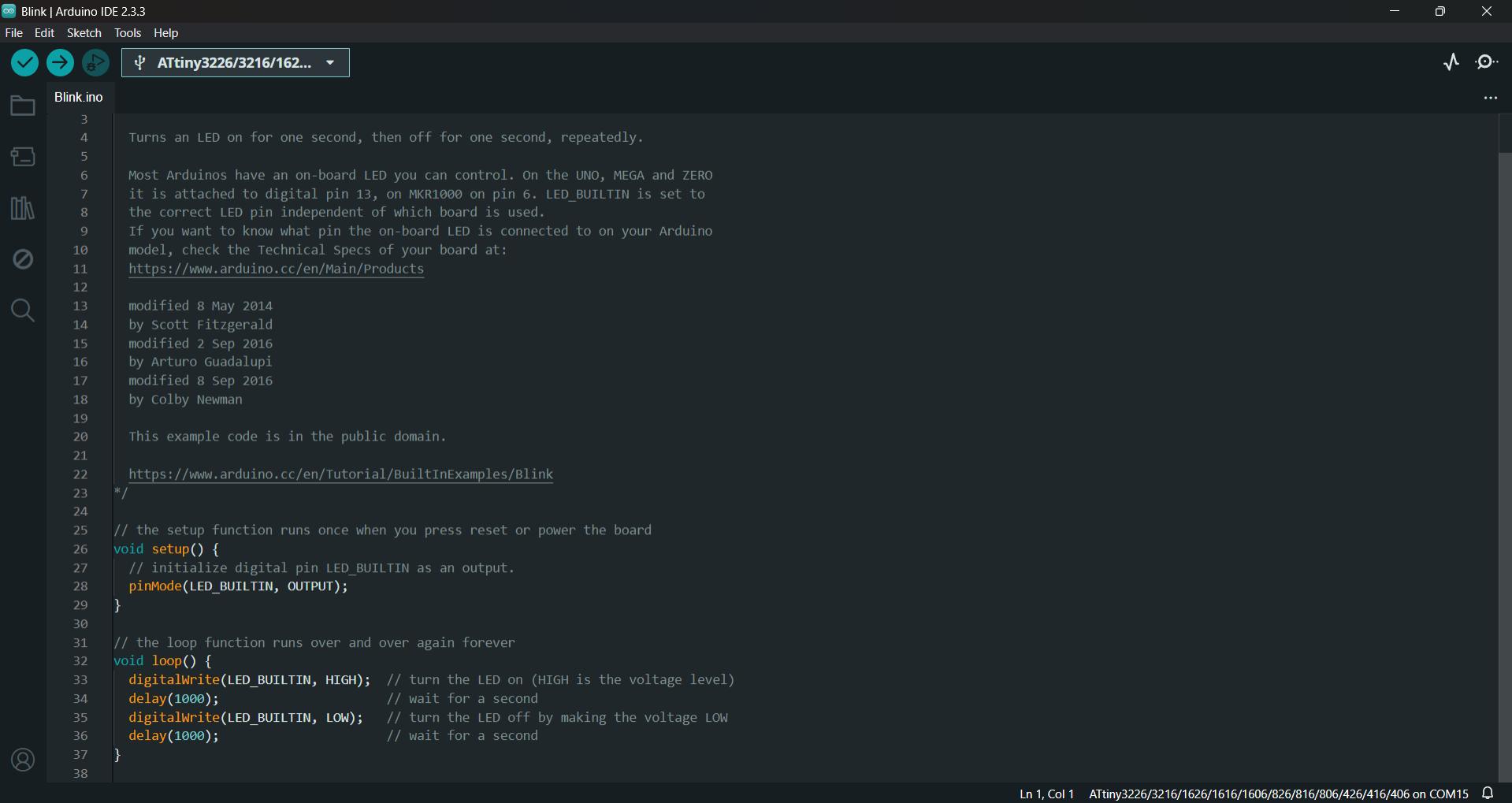
I tried the blink code example from the Arduino IDE and it works perfectly fine. File→Examples→Basics→Blink.
 |
 |
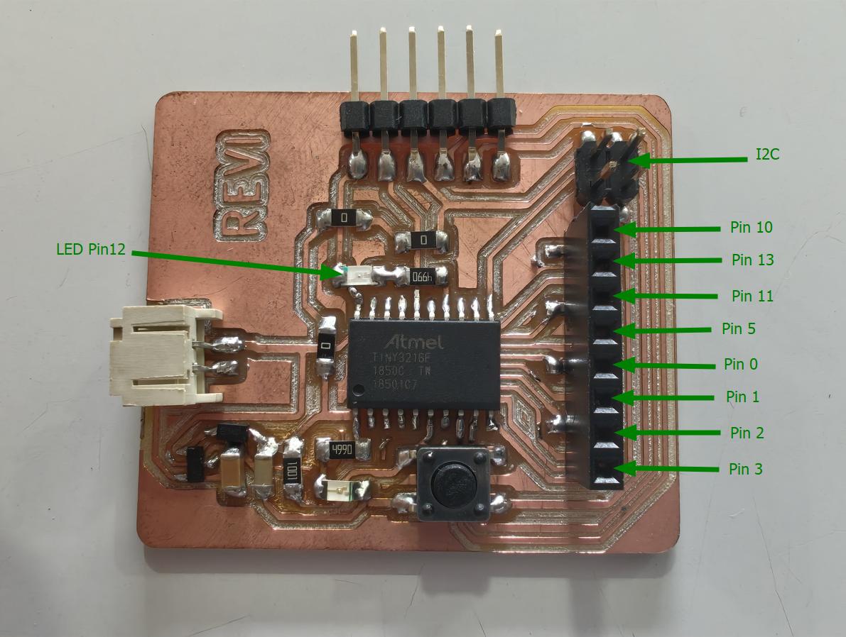
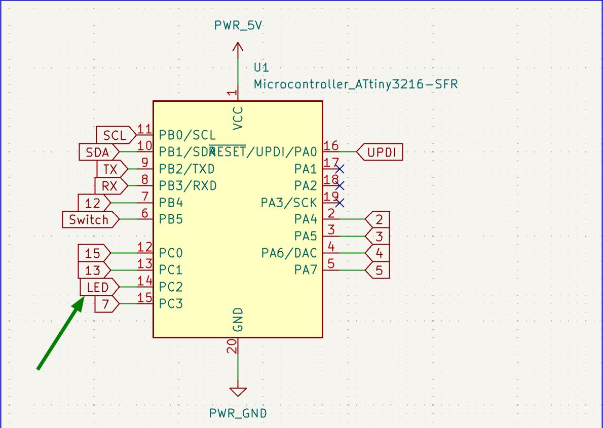
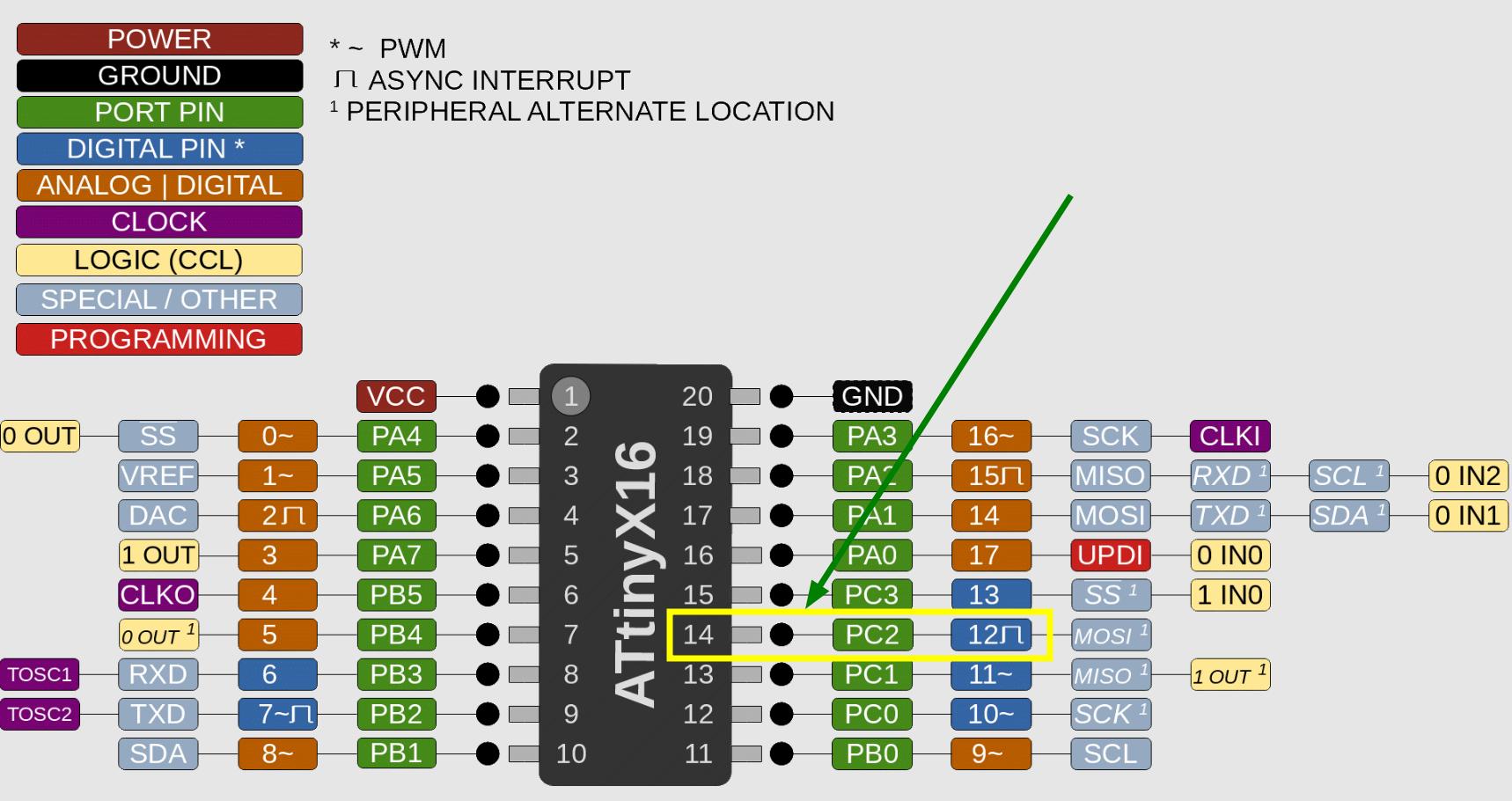
I refered the schematics of the PCB I designed and the ATtiny3216 pinout to find the pin where the LED is connected. And I found that the Led is connected to the pin 12.
 |
|
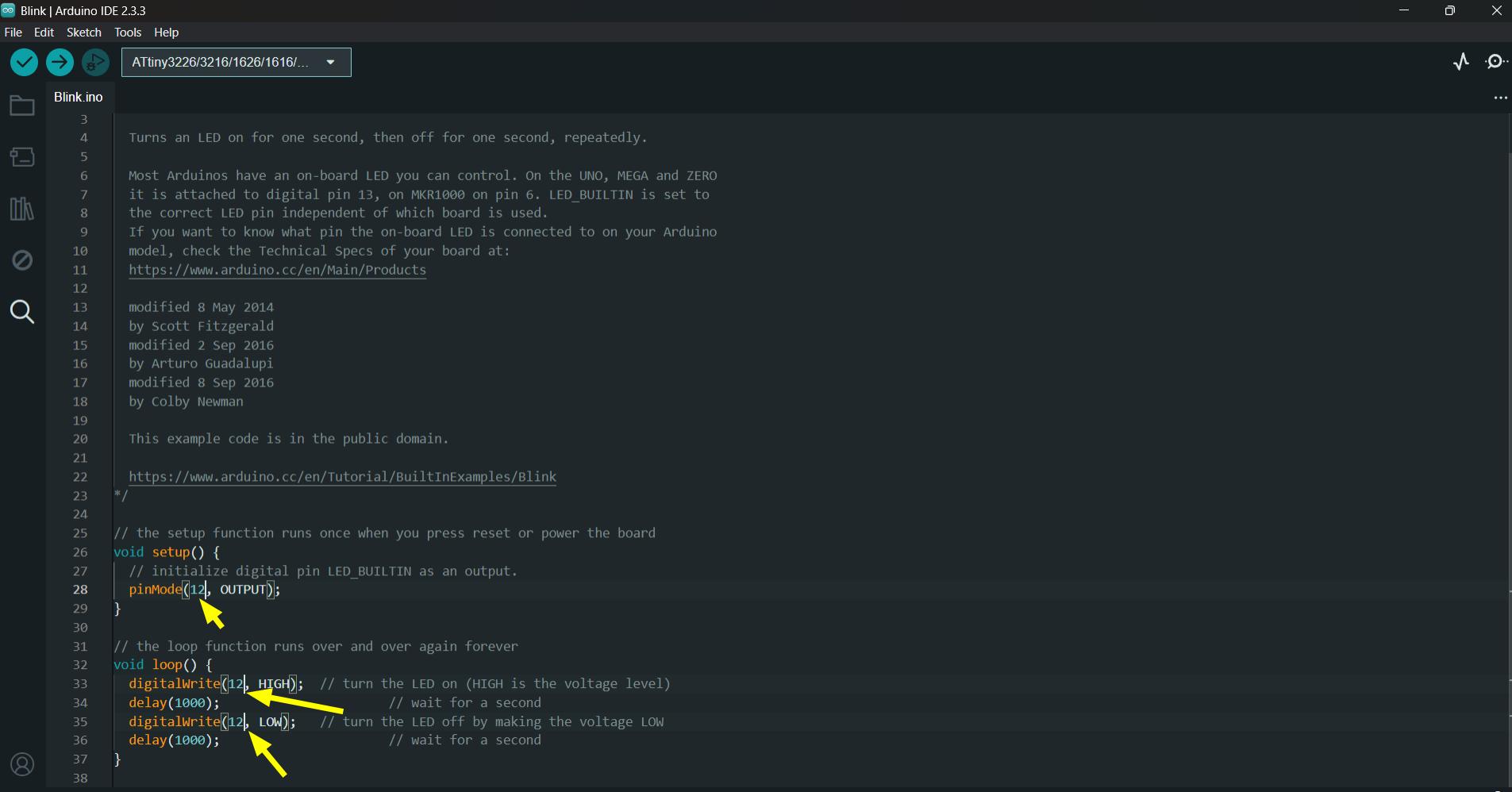
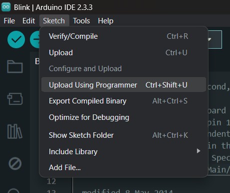
Changed the LED_BUILTIN to 12 and upload the program using Sketch→Upload using programmer.
 |
 |
I also tried 2 other programs. One is to turn on the LED while pressing the button and the other is to toggle the state of LED while pressing the button.
The code for the above videos are given below
| Code for turn ON LED
              #define LED_PIN 8
              #define BUTTON_PIN 7

              void setup() {
                pinMode(12, OUTPUT);
                pinMode(4, INPUT);
              }

              void loop() {
                if (digitalRead(BUTTON_PIN) == HIGH) {
                  digitalWrite(LED_PIN, LOW);
                }
                else {
                  digitalWrite(LED_PIN, HIGH);
                }
              }
|
Code for toggle the state of LED.
              #define LED_PIN 12
              #define BUTTON_PIN 4

              byte lastButtonState = LOW;
              byte ledState = LOW;

              void setup() {
                pinMode(LED_PIN, OUTPUT);
                pinMode(BUTTON_PIN, INPUT);
              }

              void loop() {
                byte buttonState = digitalRead(BUTTON_PIN);
                if (buttonState != lastButtonState) {
                  lastButtonState = buttonState;
                  if (buttonState == LOW) {
                    ledState = (ledState == HIGH) ? LOW: HIGH;
                    digitalWrite(LED_PIN, ledState);
                  }
                }
              }
|
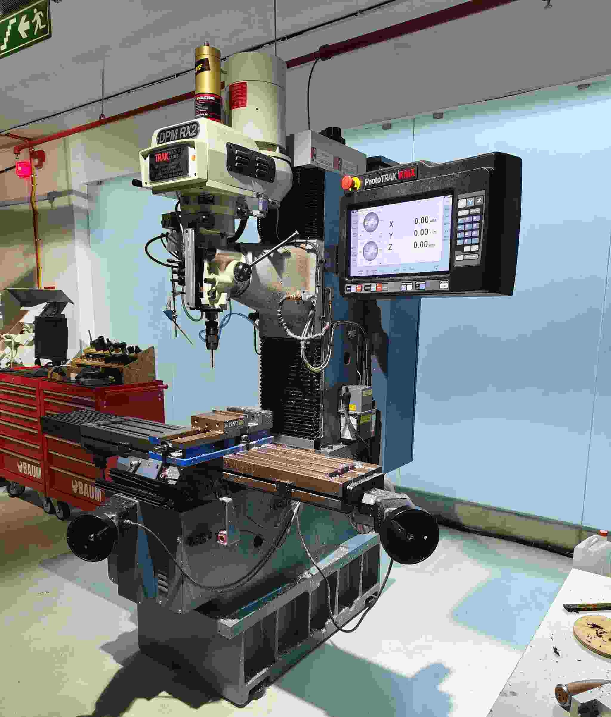
ProtoTRAK DPM RX2
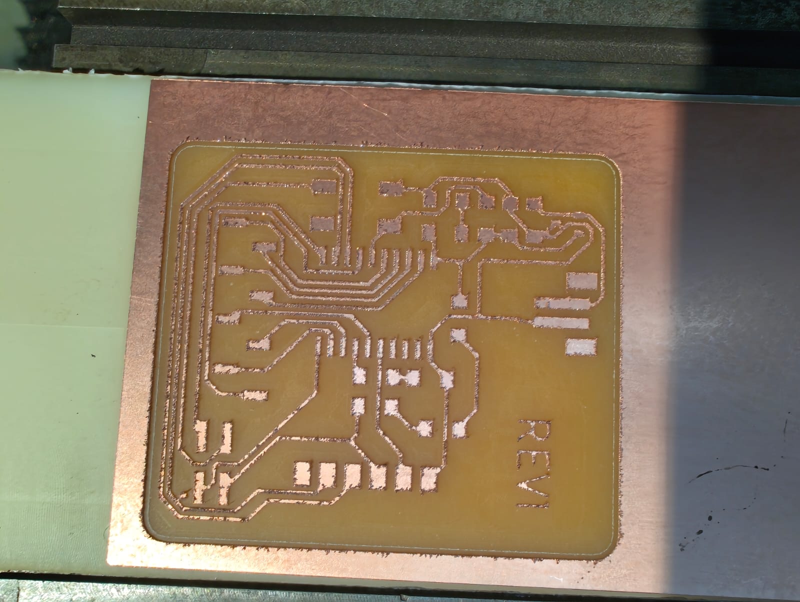
Our lab has a ProtoTrak DPM RX2 milling machine, which I have experience operating. I asked Saheen to test my PCB on this machine. He designed a metric line test, and we milled it using a 0.4mm 2-flute endmill. The results, which have been added to the group assignment page, were similar to those of the imperial line test. Additionally, I used the same design that I had milled on the Roland while maintaining the same constraints.
CAM
I used Autodesk Fusion 360 for CAM the Trak Milling machine.
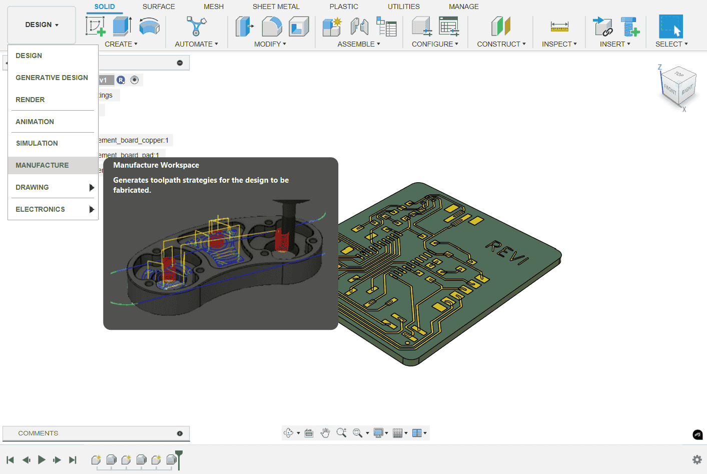
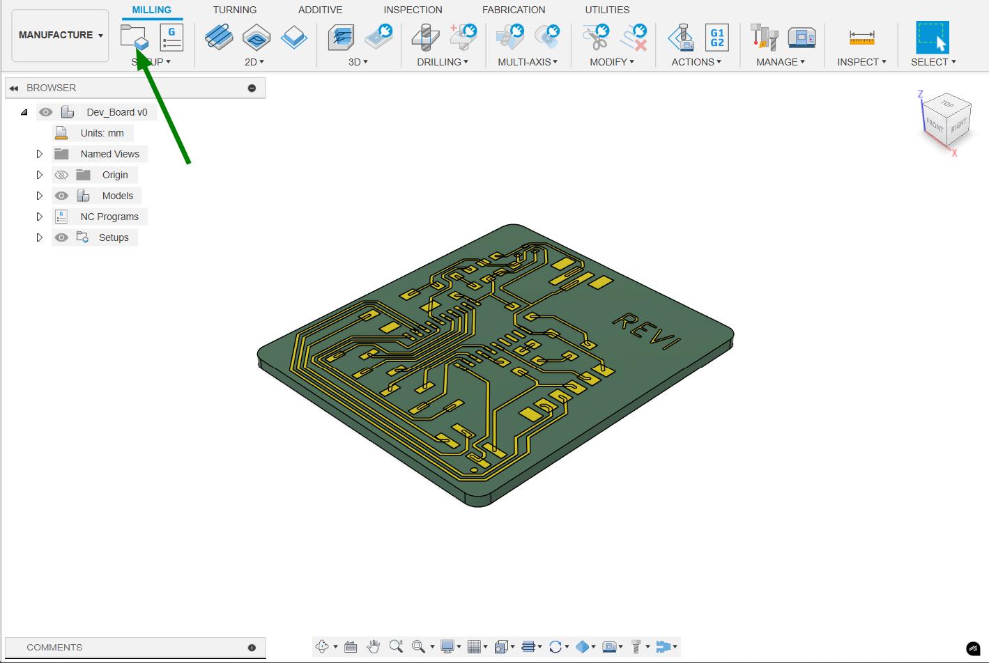
Imported the STEP file of PCB into fusion 360 and changed the workspace from design to manufacturing.
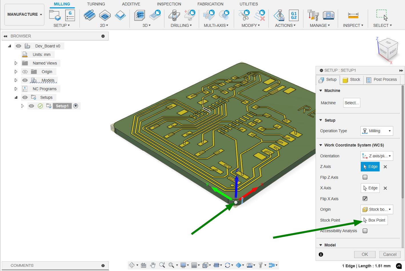
In stock setup I added the stock and specified the box point. Box point is same as the orgin in a graph.
 |
 |
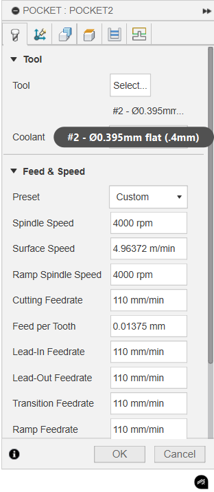
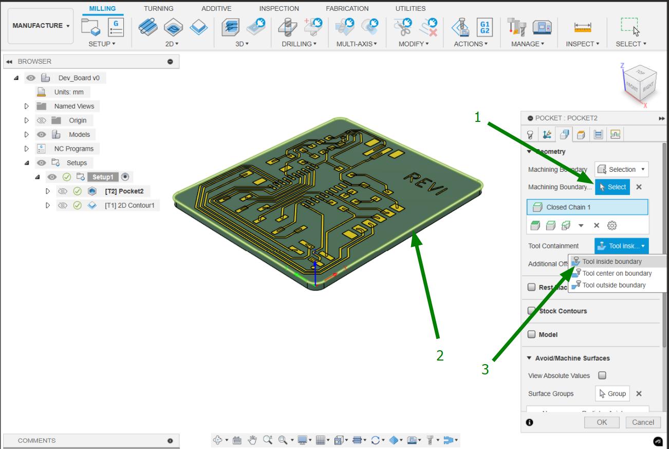
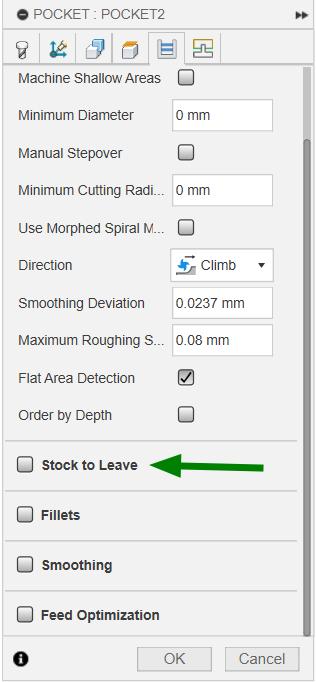
I choose pocket tool path operation for clearing the excess material. 0.4mm tool is used for milling ang the parameters I given for CAM are given below.
 |
 |
|
Simulation for Pocket.
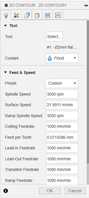
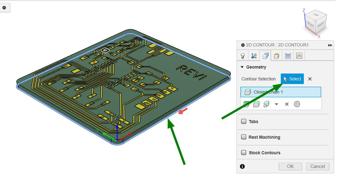
Contour tool path was used to cut the outer side of the board. 2mm 4 flute flat endmill was used for milling outline.
 |
|
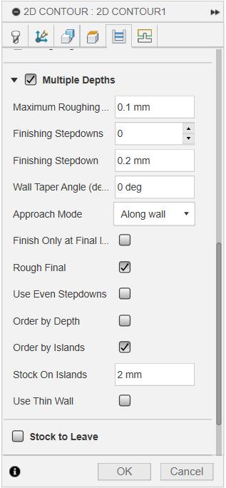 |
Simulation for Contour.
Setting up the machine for milling PCB
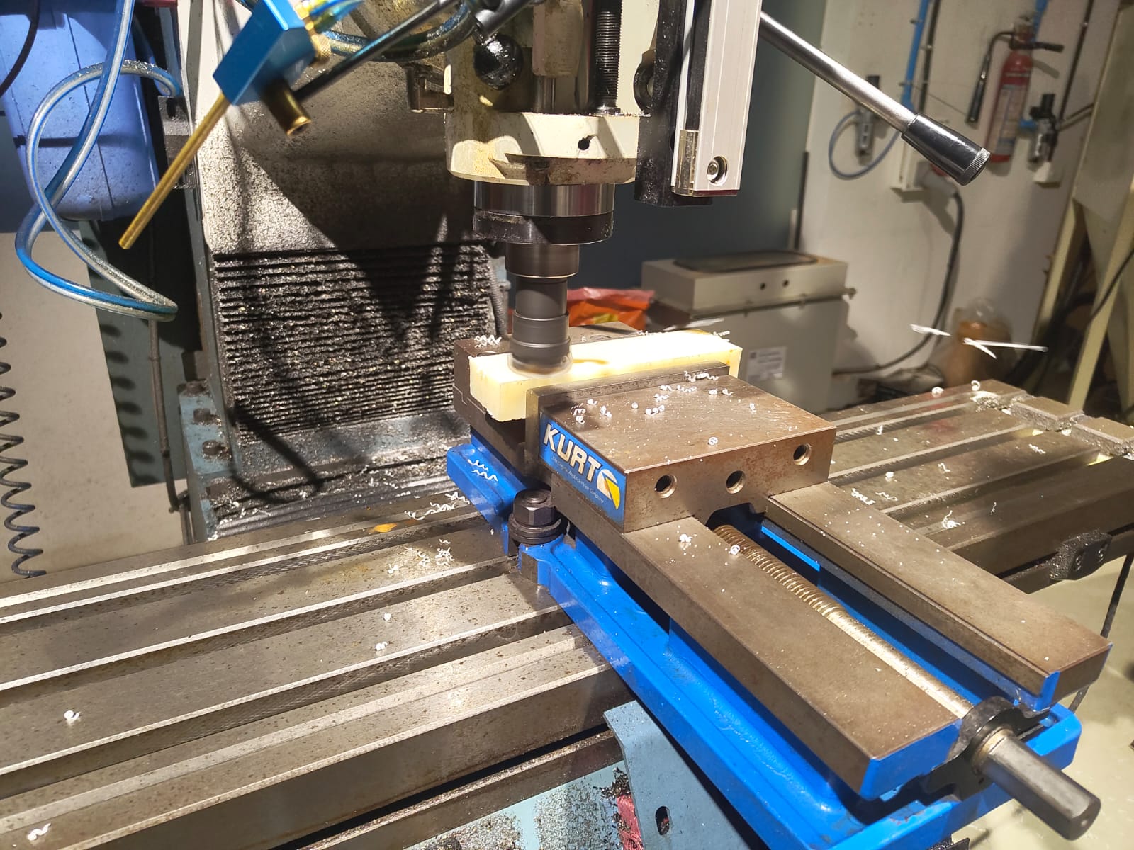
There should be a datum surface needed for sticking the copper Clad Board on to the machine's bed. So I took a waste piece of ABS and clamped it on the machine's vice. Then I faced the surface using a face milling cutter to get the datum surface.
 |
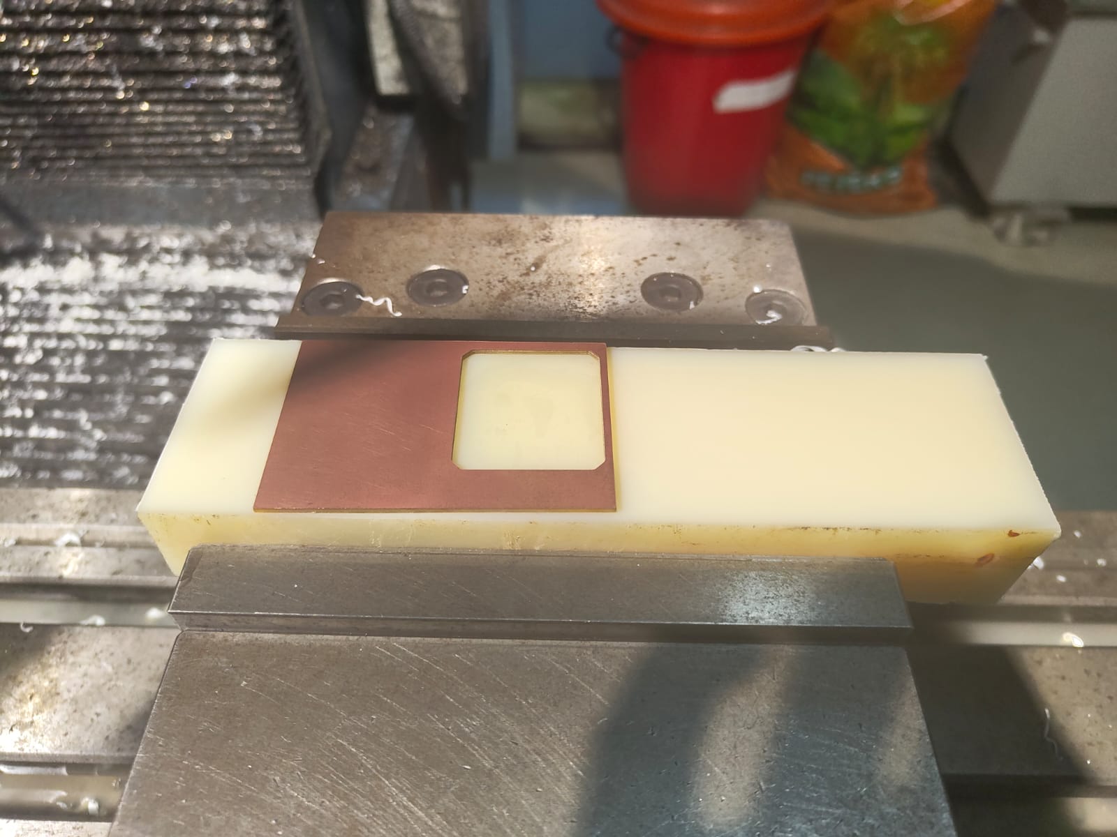 |
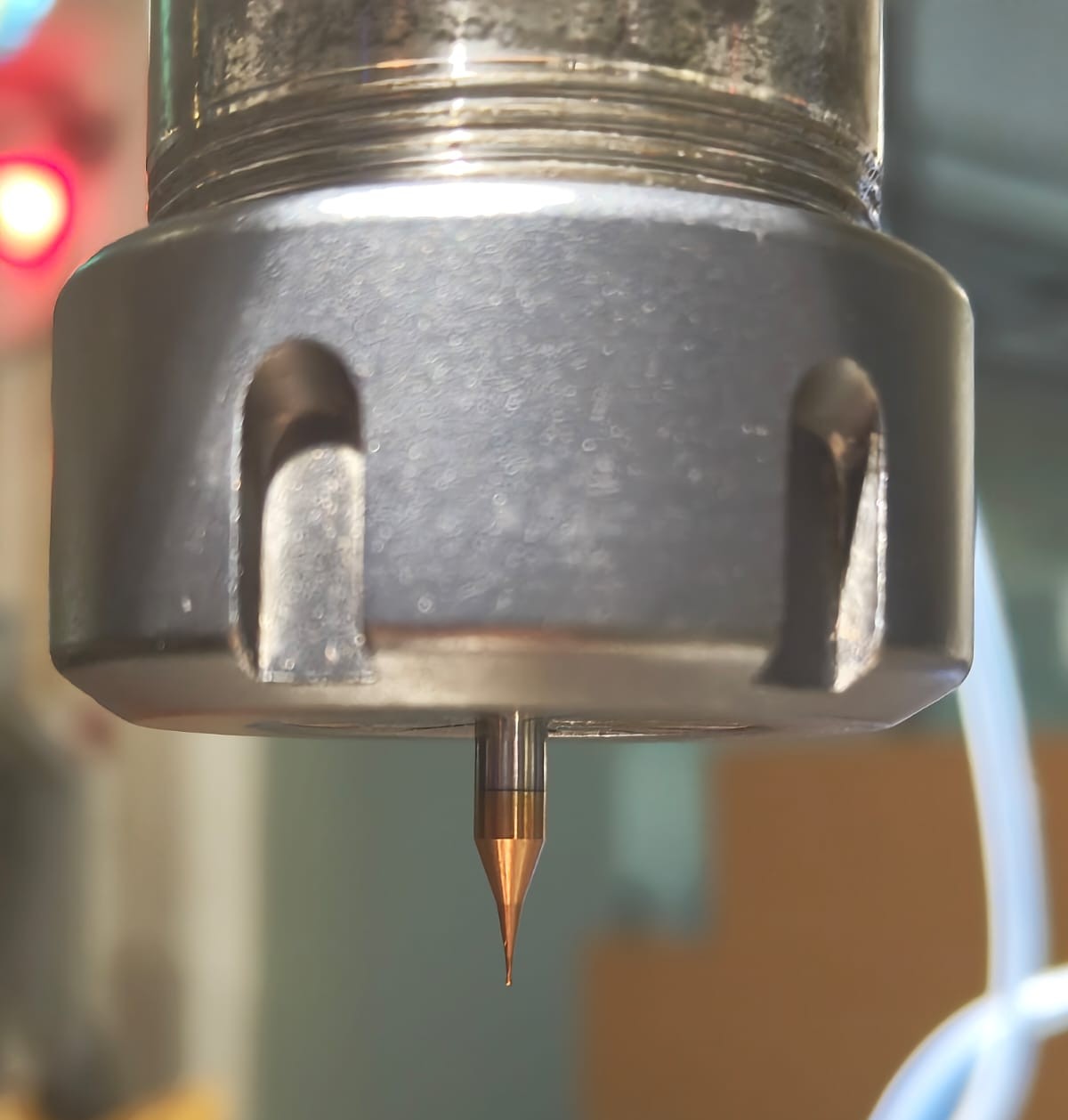
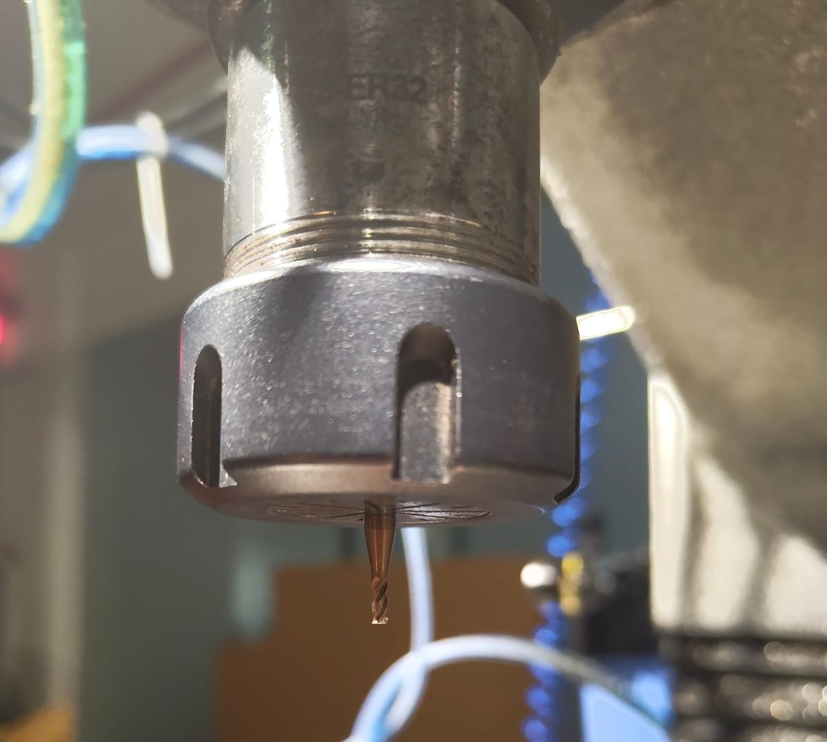
Then I loaded the program on to the machine and inserted the 0.4mm tool on to the tool holder and clamped it on to the machine. Took X,Y and Z and milled the traces.
|
 |
To cut outline, I loaded the outline program and changed the tool to 2mm and took the Z offset and run it.
|
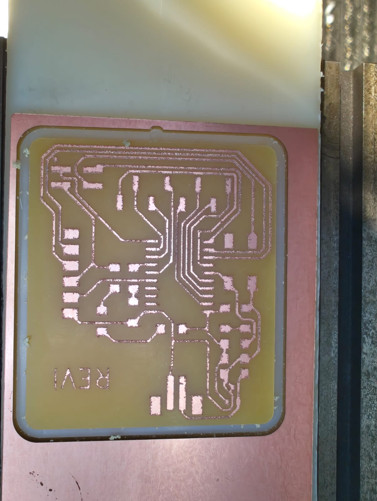 |
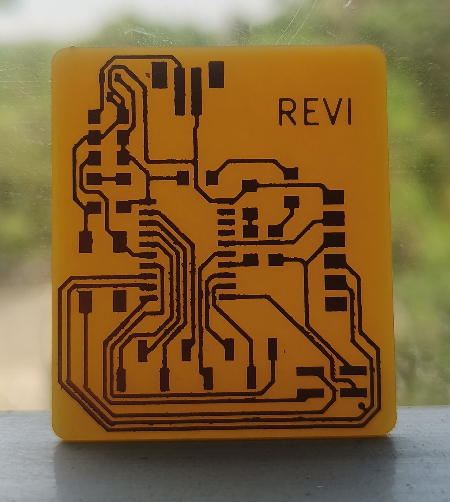
The final output and the time lapse video are shown below.
 |
Hero Shot

|  |
Conclusion
This week, I explored PCB milling using the Roland Modela MDX-20 and the ProtoTrak DPM RX2 milling machines. I successfully milled, soldered, inspected, and programmed my PCB, gaining hands-on experience with both machines.