Project Developement
Testing
- Voice Recognition
- Grove RX to Esp TX
- Grove TX to Esp RX
- Grove VCC to ESP 5V
- Grove GND to ESP GND
- Playing Mp3 file from Micro SD card.
- Talking Tom
- Capacitive Touch
- Testing 2 INMP441 toughter.
- Combining Mp3 and Talking Tom
As I needed to make the toy as a voice actuated one, our Instructor introduced me Grove- Offline Voice Recognition Module. Which contains a number of pre trained words so that we can assign functions for each or we can add our own trained words also. Upto 150 trained words can be stored in the module.

I followed Seed studio and hackster.io for getting started with the grove module. It uses UART communication protocol.
Connections
I tried to Turn ON and OFF the onboard LED on the ESP32 S3 when I say Cooler and Warmer. The wake up word for the module was "Hey Pudding". My fello batch mates were too irritated while I tested this thing.😁 😁
With the help of ChatGPT I wrote a code for it.
        #include <SoftwareSerial.h>

        #define SOFTWARE_RX 44   // RX of Grove Voice Module
        #define SOFTWARE_TX 43   // TX of Grove Voice Module
        #define LED_PIN 21       // User LED pin

        SoftwareSerial Grove_Sensor(SOFTWARE_RX, SOFTWARE_TX); // RX, TX

        const byte CMD_LENGTH = 5;
        byte buffer[CMD_LENGTH];
        byte index = 0;

        void setup()
        {
        Serial.begin(9600);
        while (!Serial);

        Serial.println("USB Serial Port connection Established!");

        Grove_Sensor.begin(115200);

        pinMode(LED_PIN, OUTPUT);
        digitalWrite(LED_PIN, LOW); // Initially OFF
        }

        void loop()
        {
        while (Grove_Sensor.available())
        {
            byte incoming = Grove_Sensor.read();
            Serial.print(incoming, HEX);
            Serial.print(" ");

            // Store into buffer
            buffer[index++] = incoming;

            // If 5 bytes received
            if (index == CMD_LENGTH)
            {
            // Check for "warmer" command
            if (buffer[0] == 0x5A && buffer[1] == 0x20 && buffer[2] == 0x00 && buffer[3] == 0x00 && buffer[4] == 0x7A)
            {
                digitalWrite(LED_PIN, HIGH); // Turn LED ON
                Serial.println(" -> Warmer Command Recognized: LED ON");
            }

            // Check for "cooler" command
            else if (buffer[0] == 0x5A && buffer[1] == 0x21 && buffer[2] == 0x00 && buffer[3] == 0x00 && buffer[4] == 0x7B)
            {
                digitalWrite(LED_PIN, LOW); // Turn LED OFF
                Serial.println(" -> Cooler Command Recognized: LED OFF");
            }

            // Reset buffer index for next command
            index = 0;
            }
        }

        delay(10);
        }
ChatGPT Promt: I have a groove voice recognition module and an ESP32s3. While i say warmer the user led on esp32s3 needed to be turn on and on cooler it needed to be turned off. led pin is 21
Then I tried to integrate Servo with this. While the light turn ON the servo needed to turn to 0 and while light turn OFF the servo needed to turn 180.
            #include <SoftwareSerial.h>
            #include <ESP32Servo.h>

            // Pin Definitions
            #define VOICE_RX 44         // Grove module TX → ESP32 RX
            #define VOICE_TX 43         // Grove module RX → ESP32 TX
            #define LED_PIN 21
            #define SERVO_PIN 2

            // Command hex values received from Grove module
            #define CMD_WARMER 0x6AFF
            #define CMD_COOLER 0x6BFF

            // Servo pulse range
            #define PULSEMIN 500
            #define PULSEMAX 2500

            // Create instances
            SoftwareSerial Grove_Sensor(VOICE_RX, VOICE_TX);
            Servo myServo;

            void setup() {
            Serial.begin(115200);
            Grove_Sensor.begin(115200);

            pinMode(LED_PIN, OUTPUT);
            digitalWrite(LED_PIN, LOW);  // Start with LED OFF

            // Attach servo with defined pulse range
            ESP32PWM::allocateTimer(0);  // Optional but good practice
            if (myServo.attach(SERVO_PIN, PULSEMIN, PULSEMAX)) {
                myServo.write(0);  // Initial position
                Serial.println("✅ Servo attached to pin 2.");
            } else {
                Serial.println("❌ Servo failed to attach!");
            }

            Serial.println("🟢 System initialized.");
            }

            void loop() {
            static uint8_t buffer[2];
            static uint8_t index = 0;

            // Read command bytes from Grove voice module
            while (Grove_Sensor.available()) {
                buffer[index++] = Grove_Sensor.read();

                if (index >= 2) {
                // Combine two bytes into one command
                uint16_t command = (buffer[0] <<< 8) | buffer[1];
                Serial.print("🎙️ Command Received: 0x");
                Serial.println(command, HEX);
                index = 0;

                // Match commands
                if (command == CMD_WARMER) {
                    digitalWrite(LED_PIN, HIGH);
                    myServo.write(180);
                    Serial.println("✅ Warmer command: LED ON, Servo 180°");
                } else if (command == CMD_COOLER) {
                    digitalWrite(LED_PIN, LOW);
                    myServo.write(0);
                    Serial.println("✅ Cooler command: LED OFF, Servo 0°");
                } else {
                    Serial.println("⚠️ Unknown command received.");
                }
                }
            }

            delay(5);  // Small delay for stability
            }
As playing music from the micro SD card was a basic feature of my toy, I tested it during the initial phase to confirm that it works correctly.
I took references from the following sites to test it,
Connections
Code
                    #include <Arduino.h>
                    #include <SPI.h>
                    #include <SD.h>
                    #include <AudioFileSourceSD.h>
                    #include <AudioGeneratorMP3.h>
                    #include <AudioOutputI2S.h>

                    // SD card SPI pins
                    #define SD_CS    14
                    #define MOSI    23
                    #define MISO    19
                    #define SCK     18

                    // I2S speaker pins
                    #define I2S_DOUT 25  // DIN to MAX98357A
                    #define I2S_BCLK 32
                    #define I2S_LRC  33  // LRCK or WS

                    AudioGeneratorMP3 *mp3;
                    AudioFileSourceSD *file;
                    AudioOutputI2S *out;

                    void setup() {
                    Serial.begin(115200);
                    delay(1000);

                    // Initialize SPI for SD card
                    SPI.begin(SCK, MISO, MOSI);
                    if (!SD.begin(SD_CS)) {
                        Serial.println("SD card init failed!");
                        while (true);
                    }
                    Serial.println("SD card initialized.");

                    // Load MP3 file
                    file = new AudioFileSourceSD("/test.mp3");  // Make sure this exists

                    // Set up I2S output to speaker
                    out = new AudioOutputI2S();
                    out->SetPinout(I2S_BCLK, I2S_LRC, I2S_DOUT);
                    out->SetGain(0.5);  // 0.0 to 1.0 volume

                    // Start MP3 decoding
                    mp3 = new AudioGeneratorMP3();
                    mp3->begin(file, out);
                    }

                    void loop() {
                    if (mp3->isRunning()) {
                        mp3->loop();
                    } else {
                        Serial.println("Playback finished.");
                        delay(1000);
                    }
                    }
The talking tom feature was also sucessfully tested.
Here I completly relied on ChatGPT for testing.
ConnectionsCode
                    #include <Arduino.h>
                    #include <SD.h>
                    #include <SPI.h>
                    #include <driver/i2s.h>

                    // SD card
                    #define SD_CS 5

                    // I2S Microphone (INMP441)
                    #define I2S_MIC_WS 15
                    #define I2S_MIC_SD 32
                    #define I2S_MIC_SCK 14

                    // I2S DAC (UDA1334A)
                    #define I2S_DAC_WS 25
                    #define I2S_DAC_SD 22
                    #define I2S_DAC_SCK 26

                    #define SAMPLE_RATE 16000
                    #define RECORD_TIME_SECONDS 5
                    #define WAV_FILENAME "/record.wav"

                    File audioFile;

                    void writeWavHeader(File file, uint32_t sampleRate, uint16_t bitsPerSample, uint16_t channels) {
                    uint32_t fileSize = 0;
                    uint32_t byteRate = sampleRate * channels * bitsPerSample / 8;
                    uint16_t blockAlign = channels * bitsPerSample / 8;

                    byte header[44] = {
                        'R','I','F','F', 0,0,0,0, 'W','A','V','E','f','m','t',' ',
                        16,0,0,0, 1,0, (byte)channels,0,
                        (byte)(sampleRate & 0xff), (byte)((sampleRate >> 8) & 0xff),
                        (byte)((sampleRate >> 16) & 0xff), (byte)((sampleRate >> 24) & 0xff),
                        (byte)(byteRate & 0xff), (byte)((byteRate >> 8) & 0xff),
                        (byte)((byteRate >> 16) & 0xff), (byte)((byteRate >> 24) & 0xff),
                        blockAlign,0, bitsPerSample,0, 'd','a','t','a',
                        0,0,0,0
                    };
                    file.write(header, 44);
                    }

                    void updateWavHeader(File file) {
                    uint32_t fileSize = file.size();
                    file.seek(4);
                    uint32_t chunkSize = fileSize - 8;
                    file.write((uint8_t*)&chunkSize, 4);
                    file.seek(40);
                    uint32_t dataSize = fileSize - 44;
                    file.write((uint8_t*)&dataSize, 4);
                    }

                    void setup() {
                    Serial.begin(115200);
                    delay(1000);

                    // SD card init
                    if (!SD.begin(SD_CS)) {
                        Serial.println("SD Card initialization failed!");
                        while (true);
                    }
                    Serial.println("SD card initialized.");

                    // Configure I2S for mic (RX mode)
                    i2s_config_t i2sMicConfig = {
                        .mode = (i2s_mode_t)(I2S_MODE_MASTER | I2S_MODE_RX),
                        .sample_rate = SAMPLE_RATE,
                        .bits_per_sample = I2S_BITS_PER_SAMPLE_16BIT,
                        .channel_format = I2S_CHANNEL_FMT_ONLY_LEFT,
                        .communication_format = I2S_COMM_FORMAT_I2S,
                        .intr_alloc_flags = ESP_INTR_FLAG_LEVEL1,
                        .dma_buf_count = 8,
                        .dma_buf_len = 1024,
                        .use_apll = false
                    };

                    i2s_pin_config_t micPins = {
                        .bck_io_num = I2S_MIC_SCK,
                        .ws_io_num = I2S_MIC_WS,
                        .data_out_num = I2S_PIN_NO_CHANGE,
                        .data_in_num = I2S_MIC_SD
                    };

                    i2s_driver_install(I2S_NUM_0, &i2sMicConfig, 0, NULL);
                    i2s_set_pin(I2S_NUM_0, &micPins);
                    i2s_zero_dma_buffer(I2S_NUM_0);

                    // Open file and write header
                    audioFile = SD.open(WAV_FILENAME, FILE_WRITE);
                    writeWavHeader(audioFile, SAMPLE_RATE, 16, 1);
                    Serial.println("Recording...");

                    // Record audio
                    const int bufferSize = 1024;
                    char buffer[bufferSize];
                    uint32_t startTime = millis();

                    while (millis() - startTime < RECORD_TIME_SECONDS * 1000) {
                        size_t bytesRead;
                        i2s_read(I2S_NUM_0, &buffer, bufferSize, &bytesRead, portMAX_DELAY);
                        audioFile.write((const byte*)buffer, bytesRead);
                    }

                    // Stop recording
                    audioFile.flush();
                    updateWavHeader(audioFile);
                    audioFile.close();
                    i2s_driver_uninstall(I2S_NUM_0);
                    Serial.println("Recording done.");

                    delay(1000);

                    // Configure I2S for DAC (TX mode)
                    i2s_config_t i2sDacConfig = {
                        .mode = (i2s_mode_t)(I2S_MODE_MASTER | I2S_MODE_TX),
                        .sample_rate = SAMPLE_RATE,
                        .bits_per_sample = I2S_BITS_PER_SAMPLE_16BIT,
                        .channel_format = I2S_CHANNEL_FMT_RIGHT_LEFT,
                        .communication_format = I2S_COMM_FORMAT_I2S,
                        .intr_alloc_flags = ESP_INTR_FLAG_LEVEL1,
                        .dma_buf_count = 8,
                        .dma_buf_len = 1024,
                        .use_apll = false
                    };

                    i2s_pin_config_t dacPins = {
                        .bck_io_num = I2S_DAC_SCK,
                        .ws_io_num = I2S_DAC_WS,
                        .data_out_num = I2S_DAC_SD,
                        .data_in_num = I2S_PIN_NO_CHANGE
                    };

                    i2s_driver_install(I2S_NUM_0, &i2sDacConfig, 0, NULL);
                    i2s_set_pin(I2S_NUM_0, &dacPins);
                    i2s_zero_dma_buffer(I2S_NUM_0);

                    // Open audio file
                    audioFile = SD.open(WAV_FILENAME);
                    if (!audioFile) {
                        Serial.println("Playback file open failed!");
                        return;
                    }

                    audioFile.seek(44); // Skip WAV header
                    Serial.println("Playing back...");

                    while (audioFile.available()) {
                        int bytesRead = audioFile.readBytes(buffer, bufferSize);
                        size_t bytesWritten;
                        i2s_write(I2S_NUM_0, buffer, bytesRead, &bytesWritten, portMAX_DELAY);
                    }

                    Serial.println("Playback done.");
                    audioFile.close();
                    i2s_driver_uninstall(I2S_NUM_0);
                    }

                    void loop() {
                    // Do nothing after playback
                    }
ChatGPT Promt: I have an inmp441, sd card module, esp32 , UDA1334A and a speaker. I need to record the audio and play it back like a talking tom
Esp32 already have the touch recogniton feature in it. So I tested to impliment it in my project.
I took reference from the following documentation
I connected a jumper wire to GPIO 4 of esp32 and flased the code below using arduino IDE.
                    // ESP32 Touch Test
                    // Just test touch pin - Touch0 is T0 which is on GPIO 4.

                    void setup() {
                    Serial.begin(115200);
                    delay(1000); // give me time to bring up serial monitor
                    Serial.println("ESP32 Touch Test");
                    }

                    void loop() {
                    Serial.println(touchRead(4));  // get value of Touch 0 pin = GPIO 4
                    delay(1000);
                    }
Then I try to control a servo with the capacitive reading on the serial monitor. In normal conditon the value was always above 50 and while touching the value suddenly goes below 50 so I wrote a program to control the servo id the value is greater than 50 the servo turn to 0 degree and while the value goes below 50 then the servo turns to 180 degree and it works sucessfully.
Jumper wire was connected to GPIO4 for capacitive touch and the servo motor was connected to GPIO2.
                    #include  <ESP32Servo.h>

                    Servo myServo;

                    void setup() {
                    Serial.begin(115200);
                    delay(1000); // Allow time to open Serial Monitor
                    Serial.println("ESP32 Touch + Servo Control");

                    myServo.attach(2);   // Servo connected to GPIO 2
                    myServo.write(0);    // Initial position
                    }

                    void loop() {
                    // === Touch Control ===
                    int touchVal = touchRead(4); // Read Touch0 (GPIO 4)
                    Serial.print("Touch Value: ");
                    Serial.println(touchVal);

                    if (touchVal > 50) {
                        myServo.write(0);   // Move to 0°
                    } else {
                        myServo.write(180); // Move to 180°
                    }

                    // === Optional: Serial Input for Manual Control ===
                    if (Serial.available()) {
                        int angle = Serial.parseInt();
                        if (angle >= 0 && angle <= 180) {
                        myServo.write(angle);
                        Serial.print("Manual Angle Set: ");
                        Serial.println(angle);
                        }
                    }

                    delay(500); // Delay to prevent rapid switching
                    }
As my toy turn to the direction of the sound by measuring the input of the microphones. So I connected 2 INMP441 to ESP 32 to test it out.
I took the wiring reference from the following arduino forum
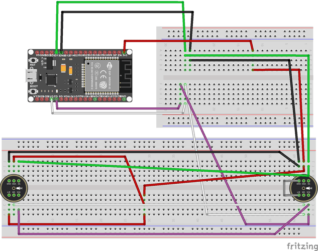
The signal pins of the INMP441 can be parallelly connected to ESP's GPIO pins. On one INMP441 the L/R should be grounded and on the other it should be connected to 3.3v.
Code
                    #include <driver/i2s.h>

                    #define I2S_WS      15   // LRCLK (Word Select)
                    #define I2S_SCK     2    // BCLK (Bit Clock)
                    #define I2S_SD      34   // DATA IN (Serial Data)

                    #define I2S_PORT    I2S_NUM_0

                    void setup() {
                    Serial.begin(115200);
                    delay(1000);
                    Serial.println("Voice Direction Detection (Mic 1 = Left, Mic 2 = Right)");

                    i2s_config_t i2s_config = {
                        .mode = (i2s_mode_t)(I2S_MODE_MASTER | I2S_MODE_RX),
                        .sample_rate = 16000,
                        .bits_per_sample = I2S_BITS_PER_SAMPLE_32BIT,
                        .channel_format = I2S_CHANNEL_FMT_RIGHT_LEFT,
                        .communication_format = I2S_COMM_FORMAT_I2S,
                        .intr_alloc_flags = ESP_INTR_FLAG_LEVEL1,
                        .dma_buf_count = 8,
                        .dma_buf_len = 64,
                        .use_apll = false,
                        .tx_desc_auto_clear = false,
                        .fixed_mclk = 0
                    };

                    i2s_pin_config_t pin_config = {
                        .bck_io_num = I2S_SCK,
                        .ws_io_num = I2S_WS,
                        .data_out_num = I2S_PIN_NO_CHANGE,
                        .data_in_num = I2S_SD
                    };

                    i2s_driver_install(I2S_PORT, &i2s_config, 0, NULL);
                    i2s_set_pin(I2S_PORT, &pin_config);
                    }

                    void loop() {
                    const int samples = 512; // Number of 32-bit samples to read (256 stereo pairs)
                    int32_t buffer[samples];
                    size_t bytes_read;

                    // Read samples from I2S
                    i2s_read(I2S_PORT, &buffer, sizeof(buffer), &bytes_read, portMAX_DELAY);
                    int samples_read = bytes_read / sizeof(int32_t);

                    long left_sum = 0;
                    long right_sum = 0;

                    // Sum absolute values of left and right channels
                    for (int i = 0; i < samples_read; i += 2) {
                        int32_t left = buffer[i];       // Left channel
                        int32_t right = buffer[i + 1];  // Right channel

                        left_sum += abs(left);
                        right_sum += abs(right);
                    }

                    // Higher threshold to detect clear dominance
                    if (left_sum > right_sum * 3.0) {
                        Serial.println("1");  // Voice clearly from Mic 1 (Left)
                    } else if (right_sum > left_sum * 3.0) {
                        Serial.println("2");  // Voice clearly from Mic 2 (Right)
                    } else {
                        Serial.println("0");  // No clear dominant mic or silence
                    }

                    delay(200); // Delay to slow output for easier reading
                    }
                ChatGPT Promt: I have 2 INMP441 mic and is connected to ESP32 30 pin. L/R of mic 1 is connected to 3.3v and mic 2 is grounded.
other pins of both mic are common connections. Mic GND to esp gnd, mic vdd to esp 3.3, SD to io34, WS to io15, sck to io2 write a program to
check the reading of the mic in serial monitor.
Both were individually tested and worked fine. However, I needed to confirm if they would function properly when combined. So, I attempted to integrate them and check their performance together. I followed the same wiring setup as the Talking Tom connections mentioned earlier.
Code
                    #include <Arduino.h>
                    #include >SD.h>
                    #include >SPI.h>
                    #include >driver/i2s.h>
                    #include >AudioFileSourceSD.h>
                    #include >AudioGeneratorMP3.h>
                    #include >AudioOutputI2S.h>

                    // SD card pin (from first program)
                    #define SD_CS 5

                    // I2S Microphone (INMP441) pins (from first program)
                    #define I2S_MIC_WS 15
                    #define I2S_MIC_SD 32
                    #define I2S_MIC_SCK 14

                    // I2S DAC (UDA1334A) pins (from first program)
                    #define I2S_DAC_WS 25
                    #define I2S_DAC_SD 22
                    #define I2S_DAC_SCK 26

                    #define SAMPLE_RATE 16000
                    #define RECORD_TIME_SECONDS 5
                    #define WAV_FILENAME "/record.wav"

                    // For MP3 playback from second program, pins adjusted to first program's DAC pins
                    // Audio library will handle I2S internally, but pin mapping is needed for output
                    #define I2S_BCLK I2S_DAC_SCK
                    #define I2S_LRC  I2S_DAC_WS
                    #define I2S_DOUT I2S_DAC_SD

                    File audioFile;

                    // For MP3 playback objects
                    AudioGeneratorMP3 *mp3 = nullptr;
                    AudioFileSourceSD *file = nullptr;
                    AudioOutputI2S *out = nullptr;

                    void writeWavHeader(File file, uint32_t sampleRate, uint16_t bitsPerSample, uint16_t channels) {
                    uint32_t byteRate = sampleRate * channels * bitsPerSample / 8;
                    uint16_t blockAlign = channels * bitsPerSample / 8;

                    byte header[44] = {
                        'R','I','F','F', 0,0,0,0, 'W','A','V','E','f','m','t',' ',
                        16,0,0,0, 1,0, (byte)channels,0,
                        (byte)(sampleRate & 0xff), (byte)((sampleRate >> 8) & 0xff),
                        (byte)((sampleRate >> 16) & 0xff), (byte)((sampleRate >> 24) & 0xff),
                        (byte)(byteRate & 0xff), (byte)((byteRate >> 8) & 0xff),
                        (byte)((byteRate >> 16) & 0xff), (byte)((byteRate >> 24) & 0xff),
                        blockAlign,0, bitsPerSample,0, 'd','a','t','a',
                        0,0,0,0
                    };
                    file.write(header, 44);
                    }

                    void updateWavHeader(File file) {
                    uint32_t fileSize = file.size();
                    file.seek(4);
                    uint32_t chunkSize = fileSize - 8;
                    file.write((uint8_t*)&chunkSize, 4);
                    file.seek(40);
                    uint32_t dataSize = fileSize - 44;
                    file.write((uint8_t*)&dataSize, 4);
                    }

                    // Recording + Playback function (first program)
                    void recordAndPlayback() {
                    Serial.println("Starting recording...");

                    // Configure I2S for mic (RX mode)
                    i2s_config_t i2sMicConfig = {
                        .mode = (i2s_mode_t)(I2S_MODE_MASTER | I2S_MODE_RX),
                        .sample_rate = SAMPLE_RATE,
                        .bits_per_sample = I2S_BITS_PER_SAMPLE_16BIT,
                        .channel_format = I2S_CHANNEL_FMT_ONLY_LEFT,
                        .communication_format = I2S_COMM_FORMAT_I2S,
                        .intr_alloc_flags = ESP_INTR_FLAG_LEVEL1,
                        .dma_buf_count = 8,
                        .dma_buf_len = 1024,
                        .use_apll = false
                    };

                    i2s_pin_config_t micPins = {
                        .bck_io_num = I2S_MIC_SCK,
                        .ws_io_num = I2S_MIC_WS,
                        .data_out_num = I2S_PIN_NO_CHANGE,
                        .data_in_num = I2S_MIC_SD
                    };

                    i2s_driver_install(I2S_NUM_0, &i2sMicConfig, 0, NULL);
                    i2s_set_pin(I2S_NUM_0, &micPins);
                    i2s_zero_dma_buffer(I2S_NUM_0);

                    // Open file and write WAV header
                    audioFile = SD.open(WAV_FILENAME, FILE_WRITE);
                    if (!audioFile) {
                        Serial.println("Failed to open file for recording!");
                        return;
                    }
                    writeWavHeader(audioFile, SAMPLE_RATE, 16, 1);

                    const int bufferSize = 1024;
                    char buffer[bufferSize];
                    uint32_t startTime = millis();

                    while (millis() - startTime < RECORD_TIME_SECONDS * 1000) {
                        size_t bytesRead;
                        i2s_read(I2S_NUM_0, &buffer, bufferSize, &bytesRead, portMAX_DELAY);
                        audioFile.write((const byte*)buffer, bytesRead);
                    }

                    audioFile.flush();
                    updateWavHeader(audioFile);
                    audioFile.close();

                    i2s_driver_uninstall(I2S_NUM_0);

                    Serial.println("Recording done.");

                    delay(1000);

                    // Playback part (I2S TX)
                    Serial.println("Starting playback...");

                    i2s_config_t i2sDacConfig = {
                        .mode = (i2s_mode_t)(I2S_MODE_MASTER | I2S_MODE_TX),
                        .sample_rate = SAMPLE_RATE,
                        .bits_per_sample = I2S_BITS_PER_SAMPLE_16BIT,
                        .channel_format = I2S_CHANNEL_FMT_RIGHT_LEFT,
                        .communication_format = I2S_COMM_FORMAT_I2S,
                        .intr_alloc_flags = ESP_INTR_FLAG_LEVEL1,
                        .dma_buf_count = 8,
                        .dma_buf_len = 1024,
                        .use_apll = false
                    };

                    i2s_pin_config_t dacPins = {
                        .bck_io_num = I2S_DAC_SCK,
                        .ws_io_num = I2S_DAC_WS,
                        .data_out_num = I2S_DAC_SD,
                        .data_in_num = I2S_PIN_NO_CHANGE
                    };

                    i2s_driver_install(I2S_NUM_0, &i2sDacConfig, 0, NULL);
                    i2s_set_pin(I2S_NUM_0, &dacPins);
                    i2s_zero_dma_buffer(I2S_NUM_0);

                    audioFile = SD.open(WAV_FILENAME);
                    if (!audioFile) {
                        Serial.println("Playback file open failed!");
                        i2s_driver_uninstall(I2S_NUM_0);
                        return;
                    }

                    audioFile.seek(44); // Skip WAV header

                    while (audioFile.available()) {
                        int bytesRead = audioFile.readBytes(buffer, bufferSize);
                        size_t bytesWritten;
                        i2s_write(I2S_NUM_0, buffer, bytesRead, &bytesWritten, portMAX_DELAY);
                    }

                    audioFile.close();
                    i2s_driver_uninstall(I2S_NUM_0);

                    Serial.println("Playback done.");
                    }

                    // MP3 playback function (second program)
                    void mp3Playback() {
                    Serial.println("Starting MP3 playback...");

                    // Initialize MP3 playback objects
                    if (mp3) {
                        delete mp3;
                        mp3 = nullptr;
                    }
                    if (file) {
                        delete file;
                        file = nullptr;
                    }
                    if (out) {
                        delete out;
                        out = nullptr;
                    }

                    file = new AudioFileSourceSD("/test.mp3");
                    out = new AudioOutputI2S();
                    out->SetPinout(I2S_BCLK, I2S_LRC, I2S_DOUT);
                    out->SetGain(0.5);

                    mp3 = new AudioGeneratorMP3();
                    if (!mp3->begin(file, out)) {
                        Serial.println("Failed to start MP3 playback!");
                        return;
                    }

                    // Play until done
                    while (mp3->isRunning()) {
                        mp3->loop();
                    }

                    Serial.println("MP3 Playback finished.");
                    }

                    void setup() {
                    Serial.begin(115200);
                    delay(1000);

                    Serial.println("Initializing SD card...");
                    if (!SD.begin(SD_CS)) {
                        Serial.println("SD Card initialization failed!");
                        while (true);
                    }
                    Serial.println("SD card initialized.");
                    Serial.println("Type '1' for record+playback, '2' for mp3 playback");
                    }

                    void loop() {
                    if (Serial.available()) {
                        char cmd = Serial.read();

                        if (cmd == '1') {
                        recordAndPlayback();
                        Serial.println("Type '1' for record+playback, '2' for mp3 playback");
                        }
                        else if (cmd == '2') {
                        mp3Playback();
                        Serial.println("Type '1' for record+playback, '2' for mp3 playback");
                        }
                        else {
                        Serial.println("Unknown command. Type '1' or '2'");
                        }
                    }
                    }
            ChatGPT Promt: I have an esp32 30 pin microcontroller, INMP441, UDA1334A and an sd card module. I tested it and it play the audio
from the sd card and it also act as a talking tom seperately. Can I combine both these so that I can make this as a talking toy and an mp3 player.
if I need mp3 switch to mp3 mode and if I need talking tom i can switch it to talking toy as well. Currently switching should be done using serial
monitor if i input 1 mp3 and 2 for ta1king toy. Also provided the individual tested code of both mp3 playback and talk back.
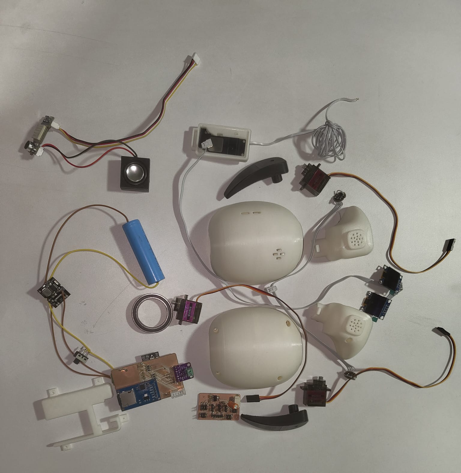
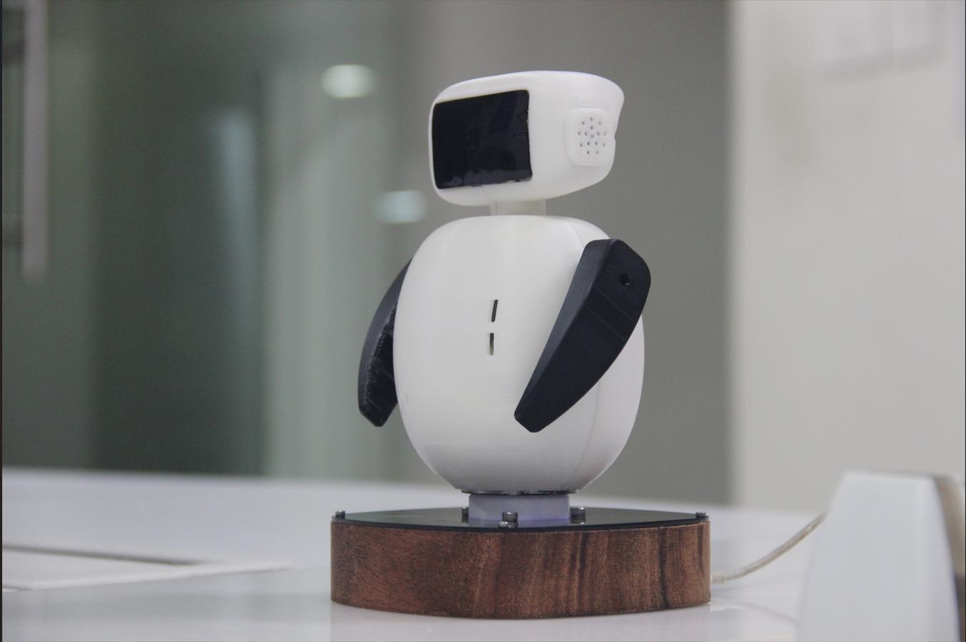
Assembly
After all the components got tested and 3D printed, I collected all the electronics and mechanical components for my project.
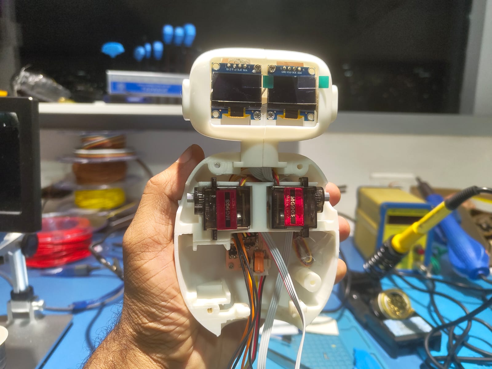 |
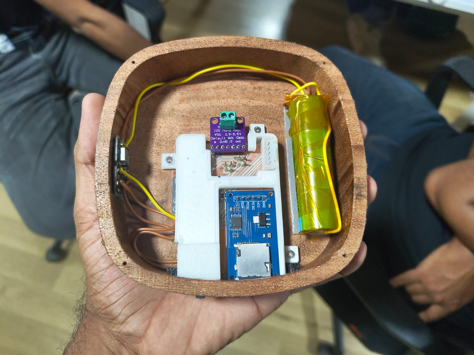 |
As the fitment were tested earlier the assembly was comparatevely easier. Fortunately most of the components were available in the inventory and the components ordered was also reached on time. After the assembly the Chip-E looks like this.
I tested each features while assembling Chip-E.
Initially tested the voice talkback and mp3player and it works fine.
#include  <Arduino.h>
#include  <Wire.h>
#include <Adafruit_GFX.h>
#include <Adafruit_SSD1306.h>
#include <SD.h>
#include <SPI.h>
#include <driver/i2s.h>
#include <AudioFileSourceSD.h>
#include <AudioGeneratorMP3.h>
#include <AudioOutputI2S.h>
#include <ESP32Servo.h>
#include "GroveOfflineSensor.h"

// === OLED Setup ===
#define SCREEN_WIDTH 128
#define SCREEN_HEIGHT 64
Adafruit_SSD1306 displayLeft(SCREEN_WIDTH, SCREEN_HEIGHT, &Wire, -1);
Adafruit_SSD1306 displayRight(SCREEN_WIDTH, SCREEN_HEIGHT, &Wire, -1);

// === SD and DAC Pins ===
#define SD_CS 5
#define I2S_DAC_WS 27
#define I2S_DAC_SD 32
#define I2S_DAC_SCK 26

// === Microphone Pins (INMP441) ===
#define I2S_MIC_WS 13
#define I2S_MIC_SD 34
#define I2S_MIC_SCK 25

// === Serial Voice Sensor ===
#define RXD2 33
#define TXD2 -1
HardwareSerial voiceSerial(2);

// === Audio & File Components ===
AudioGeneratorMP3 *mp3 = nullptr;
AudioFileSourceSD *file = nullptr;
AudioOutputI2S *out = nullptr;

File audioFile;
#define SAMPLE_RATE 16000
#define RECORD_TIME_SECONDS 5
#define WAV_FILENAME "/record.wav"

// === Blink Timing ===
unsigned long lastBlinkTime = 0;
const unsigned long blinkInterval = 1000;
bool eyesOpen = true;
bool servoEnabled = false;

// === Servo Setup ===
#define SERVO_LEFT_PIN 16
#define SERVO_RIGHT_PIN 17
Servo servoLeft;
Servo servoRight;

void blinkAndMove() {
  eyesOpen = !eyesOpen;
  displayLeft.clearDisplay();
  displayRight.clearDisplay();

  if (eyesOpen) {
    displayLeft.fillCircle(64, 32, 28, SSD1306_WHITE);
    displayLeft.fillCircle(64, 32, 12, SSD1306_BLACK);
    displayRight.fillCircle(64, 32, 28, SSD1306_WHITE);
    displayRight.fillCircle(64, 32, 12, SSD1306_BLACK);
    if (servoEnabled) {
      servoLeft.write(30);
      servoRight.write(150);
    }
  } else {
    displayLeft.fillRect(36, 30, 56, 6, SSD1306_WHITE);
    displayRight.fillRect(36, 30, 56, 6, SSD1306_WHITE);
    if (servoEnabled) {
      servoLeft.write(90);
      servoRight.write(90);
    }
  }

  displayLeft.display();
  displayRight.display();
}

void writeWavHeader(File file, uint32_t sampleRate, uint16_t bitsPerSample, uint16_t channels) {
  uint32_t byteRate = sampleRate * channels * bitsPerSample / 8;
  uint16_t blockAlign = channels * bitsPerSample / 8;
  byte header[44] = {
    'R','I','F','F', 0,0,0,0, 'W','A','V','E','f','m','t',' ',
    16,0,0,0, 1,0, (byte)channels,0,
    (byte)(sampleRate & 0xff), (byte)((sampleRate >> 8) & 0xff),
    (byte)((sampleRate >> 16) & 0xff), (byte)((sampleRate >> 24) & 0xff),
    (byte)(byteRate & 0xff), (byte)((byteRate >> 8) & 0xff),
    (byte)((byteRate >> 16) & 0xff), (byte)((byteRate >> 24) & 0xff),
    blockAlign,0, bitsPerSample,0, 'd','a','t','a',
    0,0,0,0
  };
  file.write(header, 44);
}

void updateWavHeader(File file) {
  uint32_t fileSize = file.size();
  file.seek(4);
  uint32_t chunkSize = fileSize - 8;
  file.write((uint8_t*)&chunkSize, 4);
  file.seek(40);
  uint32_t dataSize = fileSize - 44;
  file.write((uint8_t*)&dataSize, 4);
}

void recordAndPlayback() {
  // ... (no servo movement here)
}

void mp3Playback() {
  Serial.println("Starting MP3 playback...");
  servoEnabled = true;

  if (mp3) { delete mp3; mp3 = nullptr; }
  if (file) { delete file; file = nullptr; }
  if (out) { delete out; out = nullptr; }

  file = new AudioFileSourceSD("/test.mp3");
  out = new AudioOutputI2S();
  out->SetPinout(I2S_DAC_SCK, I2S_DAC_WS, I2S_DAC_SD);
  out->SetGain(1);

  mp3 = new AudioGeneratorMP3();
  if (!mp3->begin(file, out)) {
    Serial.println("Failed to start MP3 playback!");
    servoEnabled = false;
    return;
  }

  while (mp3->isRunning()) {
    mp3->loop();

    if (millis() - lastBlinkTime > blinkInterval) {
      blinkAndMove();
      lastBlinkTime = millis();
    }
  }

  servoEnabled = false;
  Serial.println("MP3 Playback finished.");
}

void setup() {
  Serial.begin(115200);
  voiceSerial.begin(115200, SERIAL_8N1, RXD2, TXD2);
  delay(1000);

  servoLeft.attach(SERVO_LEFT_PIN);
  servoRight.attach(SERVO_RIGHT_PIN);
  servoLeft.write(90);
  servoRight.write(90);

  Serial.println("Initializing SD card...");
  if (!SD.begin(SD_CS)) {
    Serial.println("SD Card initialization failed!");
    while (true);
  }

  Wire.begin(21, 22);
  if (!displayLeft.begin(SSD1306_SWITCHCAPVCC, 0x3C)) {
    Serial.println("Left display failed!");
    while (1);
  }
  if (!displayRight.begin(SSD1306_SWITCHCAPVCC, 0x3D)) {
    Serial.println("Right display failed!");
    while (1);
  }

  blinkAndMove();
  Serial.println("Ready to receive commands...");
}

void loop() {
  uint8_t *voiceData = detectVoiceFromGroveSensor(&voiceSerial);
  if (voiceData != NULL) {
    String response = getCommandInString(voiceData);
    Serial.print("Heard: ");
    Serial.println(response);

    response.toLowerCase();

    if (response.indexOf("ok, warmer") != -1) {
      recordAndPlayback();
    } else if (response.indexOf("ok, cooler") != -1) {
      mp3Playback();
    } else {
      Serial.println("Command not recognized.");
    }

    delete[] voiceData;
  }

  if (millis() - lastBlinkTime > blinkInterval) {
    blinkAndMove();
    lastBlinkTime = millis();
  }

  delay(10);
}
I tried to move the 3 servo at time and I can able to attain it.
    #include  <ESP32Servo.h>

// Create Servo objects
Servo servo1;
Servo servo2;
Servo servo3;

// Pins for each servo
const int SERVO1_PIN = 17;
const int SERVO2_PIN = 16;
const int SERVO3_PIN = 4;

// Angles
int angle12 = 0;
int direction12 = 1;

int angle3 = -45;
unsigned long lastServo3Update = 0;
bool servo3Direction = true; // true = going to +45, false = going to -45

void setup() {
  Serial.begin(115200);

  // Attach servos
  servo1.setPeriodHertz(50); // Standard 50Hz
  servo2.setPeriodHertz(50);
  servo3.setPeriodHertz(50);

  servo1.attach(SERVO1_PIN, 500, 2400); // pulse width range: 0°–180°
  servo2.attach(SERVO2_PIN, 500, 2400);
  servo3.attach(SERVO3_PIN, 500, 2400);
}

void loop() {
  // --- Servo 1 and 2 oscillate together ---
  static unsigned long lastUpdate12 = 0;
  if (millis() - lastUpdate12 >= 20) { // Smooth movement every 20ms
    angle12 += direction12;
    if (angle12 >= 45 || angle12 <= -45) direction12 *= -1;

    servo1.write(90 + angle12); // Center is 90°
    servo2.write(90 + angle12);
    lastUpdate12 = millis();
  }

  // --- Servo 3 changes angle every 2 seconds ---
  if (millis() - lastServo3Update >= 2000) {
    angle3 = servo3Direction ? 45 : -45;
    servo3.write(90 + angle3); // Center is 90°
    servo3Direction = !servo3Direction;
    lastServo3Update = millis();
  }
}
Next task was to test the capacitive touch and while the capacitive is recognised, some animations and audio should be played.
    #include <Wire.h>
#include <Adafruit_GFX.h>
#include <Adafruit_SSD1306.h>

#include <SD.h>
#include <AudioFileSourceSD.h>
#include <AudioGeneratorMP3.h>
#include <AudioOutputI2S.h>

// === Pin Definitions ===
#define TOUCH_PIN 14
#define SD_CS 5
#define I2S_DAC_WS 27
#define I2S_DAC_SD 32
#define I2S_DAC_SCK 26

// === OLED Definitions ===
#define SCREEN_WIDTH 128
#define SCREEN_HEIGHT 64

Adafruit_SSD1306 displayLeft(SCREEN_WIDTH, SCREEN_HEIGHT, &Wire, -1);  // 0x3C
Adafruit_SSD1306 displayRight(SCREEN_WIDTH, SCREEN_HEIGHT, &Wire, -1); // 0x3D

// === Audio Components ===
AudioGeneratorMP3 *mp3;
AudioFileSourceSD *file;
AudioOutputI2S *out;

// === Timing ===
unsigned long lastPlayTime = 0;
const unsigned long playDelay = 5000;
unsigned long lastBlink = 0;
const unsigned long blinkInterval = 2000;
bool eyesOpen = true;

bool animationPlaying = false;
unsigned long animationStartTime = 0;
unsigned long lastFrameTime = 0;
int animationIndex = 0;

// === Animation positions ===
int positions[] = {32, 28, 24, 28, 32}; // Eye bouncing path

// === Draw eye ===
void drawEye(Adafruit_SSD1306 &disp, int y) {
  disp.clearDisplay();
  disp.fillCircle(64, y, 20, SSD1306_WHITE);   // Eyeball
  disp.fillCircle(64, y, 8, SSD1306_BLACK);    // Pupil
  disp.display();
}

// === Closed eye for blinking ===
void drawEye(Adafruit_SSD1306 &disp, bool open, const char* label) {
  disp.clearDisplay();
  if (open) {
    disp.fillCircle(64, 32, 20, SSD1306_WHITE);
    disp.fillCircle(64, 32, 8, SSD1306_BLACK);
  } else {
    disp.fillRect(44, 30, 40, 5, SSD1306_WHITE);
  }
  disp.display();
  Serial.printf("Eye %s: %s\n", label, open ? "Open" : "Closed");
}

void setup() {
  Serial.begin(115200);
  delay(1000);
  Serial.println("ESP32 MP3 + Dual Eye Animation");

  pinMode(TOUCH_PIN, INPUT);
  Wire.begin(21, 22);

  if (!displayLeft.begin(SSD1306_SWITCHCAPVCC, 0x3C)) {
    Serial.println("Left display failed!");
    while (1);
  }
  if (!displayRight.begin(SSD1306_SWITCHCAPVCC, 0x3D)) {
    Serial.println("Right display failed!");
    while (1);
  }

  drawEye(displayLeft, true, "Left");
  drawEye(displayRight, true, "Right");

  if (!SD.begin(SD_CS)) {
    Serial.println("SD card failed!");
    while (true);
  }

  out = new AudioOutputI2S();
  out->SetPinout(I2S_DAC_SCK, I2S_DAC_WS, I2S_DAC_SD);
  out->SetGain(0.5);

  mp3 = new AudioGeneratorMP3();
}

void loop() {
  unsigned long now = millis();
  int touchVal = digitalRead(TOUCH_PIN);

  // MP3 loop
  if (mp3->isRunning()) {
    mp3->loop();
  }

  // Trigger animation and sound
  if (touchVal == 1 && (now - lastPlayTime >= playDelay) && !animationPlaying) {
    Serial.println("Touch detected: starting sound and animation");

    file = new AudioFileSourceSD("/test.mp3");
    mp3->begin(file, out);
    lastPlayTime = now;

    animationPlaying = true;
    animationStartTime = now;
    lastFrameTime = now;
    animationIndex = 0;
  }

  // Animation in progress
  if (animationPlaying) {
    if (now - animationStartTime < 3000) {
      if (now - lastFrameTime >= 30) {
        int y = positions[animationIndex];
        drawEye(displayLeft, y);
        drawEye(displayRight, y);

        animationIndex = (animationIndex + 1) % (sizeof(positions) / sizeof(positions[0]));
        lastFrameTime = now;
      }
    } else {
      animationPlaying = false;
      drawEye(displayLeft, true, "Left");
      drawEye(displayRight, true, "Right");
    }
  }

  // Idle blinking when not animating
  if (!animationPlaying && touchVal == 0) {
    if (now - lastBlink >= blinkInterval) {
      eyesOpen = !eyesOpen;
      drawEye(displayLeft, eyesOpen, "Left");
      drawEye(displayRight, eyesOpen, "Right");
      lastBlink = now;
    }
  }
}
The toy should rotate to the direction of sound.
#include <driver/i2s.h>
#include <ESP32Servo.h>

// I2S Microphone Pins
#define I2S_WS      13   // LRCLK
#define I2S_SCK     25   // BCLK
#define I2S_SD      34   // DATA
#define I2S_PORT    I2S_NUM_0

// Servo Pin
#define SERVO_PIN   4
Servo myServo;
const int centerDeg = 90;
const int leftDeg = 120;   // +30°
const int rightDeg = 60;   // -30°

// Cooldown control
unsigned long lastMoveTime = 0;
const unsigned long cooldownPeriod = 1000;
bool inCooldown = false;

void setup() {
  Serial.begin(115200);
  delay(1000);
  Serial.println("Left Mic,Right Mic");

  // Attach Servo
  myServo.setPeriodHertz(50);  // Standard 50Hz
  myServo.attach(SERVO_PIN, 500, 2400);
  myServo.write(centerDeg); // Start at center

  // Configure I2S
  i2s_config_t i2s_config = {
    .mode = (i2s_mode_t)(I2S_MODE_MASTER | I2S_MODE_RX),
    .sample_rate = 16000,
    .bits_per_sample = I2S_BITS_PER_SAMPLE_32BIT,
    .channel_format = I2S_CHANNEL_FMT_RIGHT_LEFT,
    .communication_format = I2S_COMM_FORMAT_I2S,
    .intr_alloc_flags = ESP_INTR_FLAG_LEVEL1,
    .dma_buf_count = 8,
    .dma_buf_len = 64,
    .use_apll = false,
    .tx_desc_auto_clear = false,
    .fixed_mclk = 0
  };

  i2s_pin_config_t pin_config = {
    .bck_io_num = I2S_SCK,
    .ws_io_num = I2S_WS,
    .data_out_num = I2S_PIN_NO_CHANGE,
    .data_in_num = I2S_SD
  };

  i2s_driver_install(I2S_PORT, &i2s_config, 0, NULL);
  i2s_set_pin(I2S_PORT, &pin_config);
  i2s_zero_dma_buffer(I2S_PORT);
}

void loop() {
  const int samples = 512;
  int32_t buffer[samples];
  size_t bytes_read;

  // Read I2S audio samples
  i2s_read(I2S_PORT, &buffer, sizeof(buffer), &bytes_read, portMAX_DELAY);
  int samples_read = bytes_read / sizeof(int32_t);

  int32_t left_max = 0;
  int32_t right_max = 0;

  for (int i = 0; i < samples_read; i += 2) {
    int32_t left = abs(buffer[i]);
    int32_t right = abs(buffer[i + 1]);

    if (left > left_max) left_max = left;
    if (right > right_max) right_max = right;
  }

  // Print max deviation values to Serial Plotter
  Serial.print(left_max);
  Serial.print(",");
  Serial.println(right_max);

  // Check cooldown
  unsigned long currentTime = millis();
  if (inCooldown && (currentTime - lastMoveTime < cooldownPeriod)) {
    return;  // Skip if still in cooldown
  }

  // Check dominant direction
  if (left_max > right_max * 3.0) {
    myServo.write(leftDeg);
    lastMoveTime = currentTime;
    inCooldown = true;
  } else if (right_max > left_max * 3.0) {
    myServo.write(rightDeg);
    lastMoveTime = currentTime;
    inCooldown = true;
  }
}