Lumi: A TV with a secret life!
Final Project Presentation
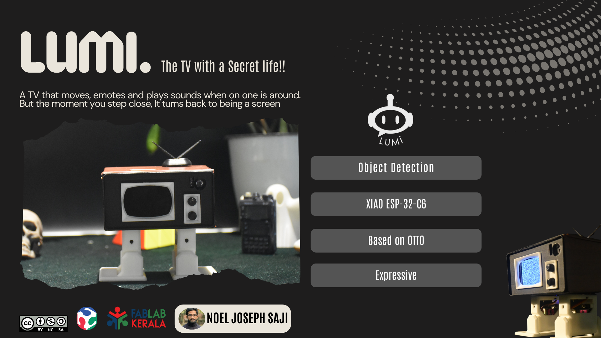
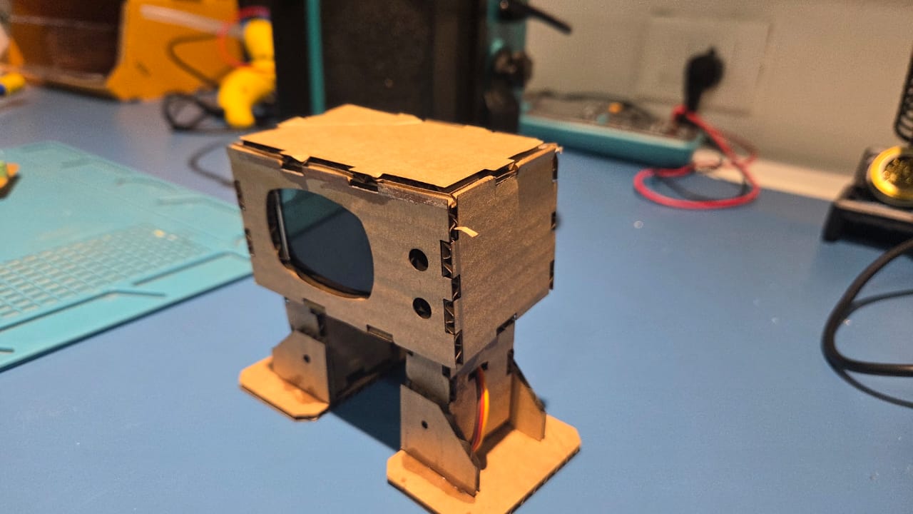
My final project is called Lumi. Essentially it is a TV. But unlike a regular TV, it is actually alive! But to see it in action, you'll need to make sure that it does not see you.
The Idea
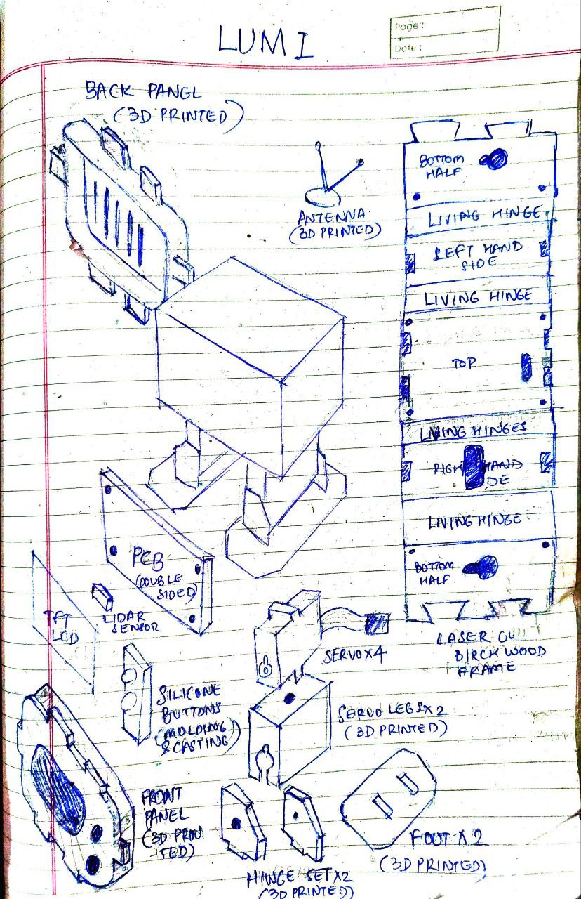
Many ideas were discussed (read Week 1), but ultimately I choose Lumi as my final project. This is how my sketch looks like after multiple revisions
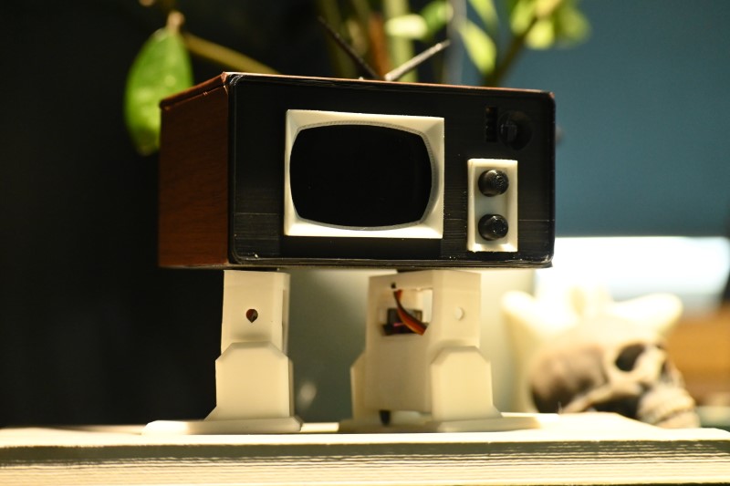
This is a comparision between a 2D render of my idea (made in Photopea) vs Lumi in real life

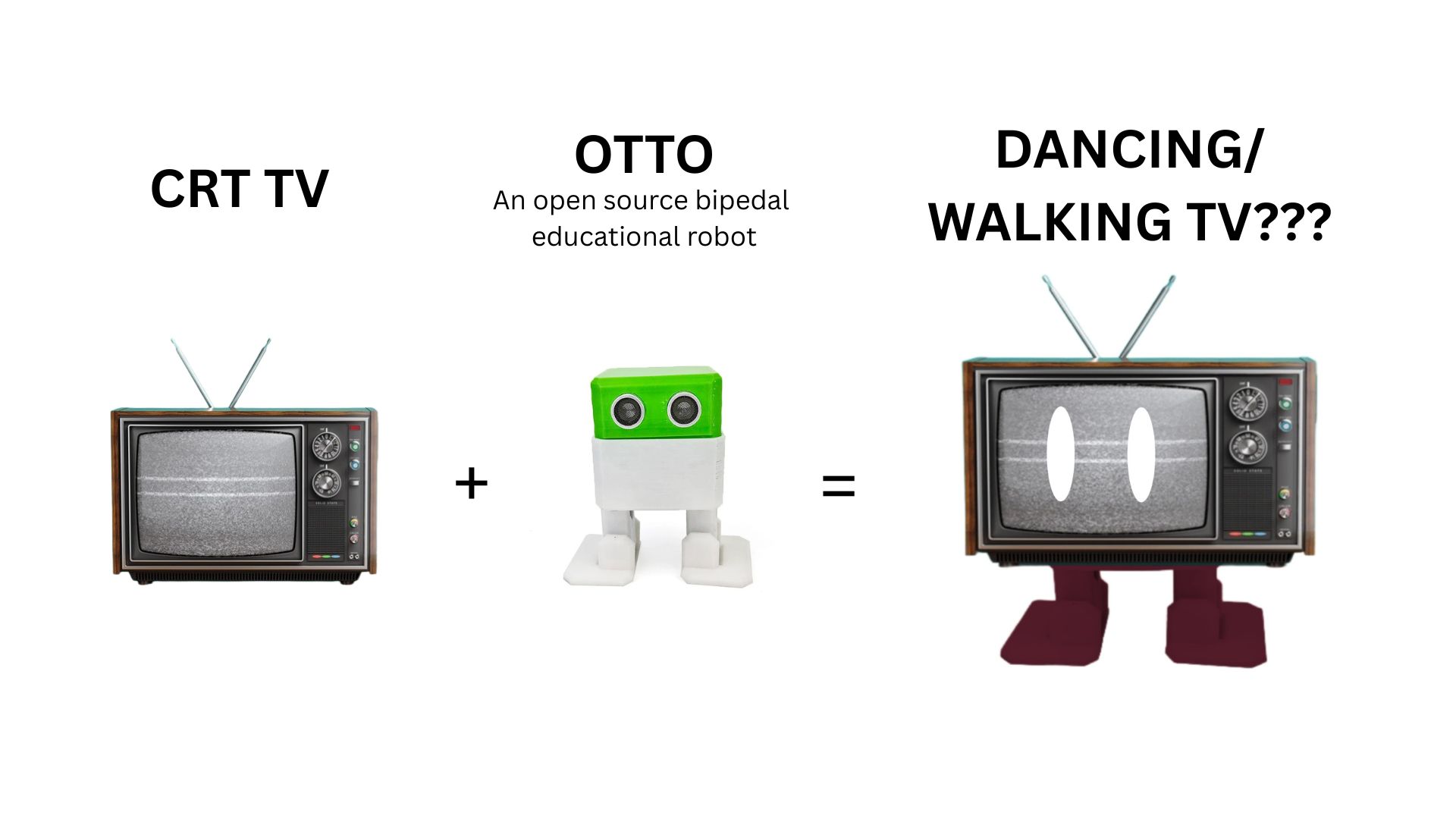
It was partly inspired by the animatronic droids at Disney, so I wanted to make a simplified version of a 'walking robot'

The legs of my design is based on an opensource bipedal educational robot design called Otto
Questions
What will it do?
Lumi is a toy robot that resembles a TV on legs. Lumi has the following key features, which have been arranged in order here
- Lumi can detect if the user comes closer than 2m to it.
- When the user is farther than 2m, Lumi behaves like a living being
- Lumi 'shuffle' walks just like Otto
- Lumi plays facial animations randomly
- Sound effects corresponding to animations will also play
- When the user is closer than 2m, Lumi 'realizes' it is being watched, it then starts behaving like a regular TV
- Lumi stops moving
- It starts playing TV footage
- Accompaning sound effects will be playes from its speakers
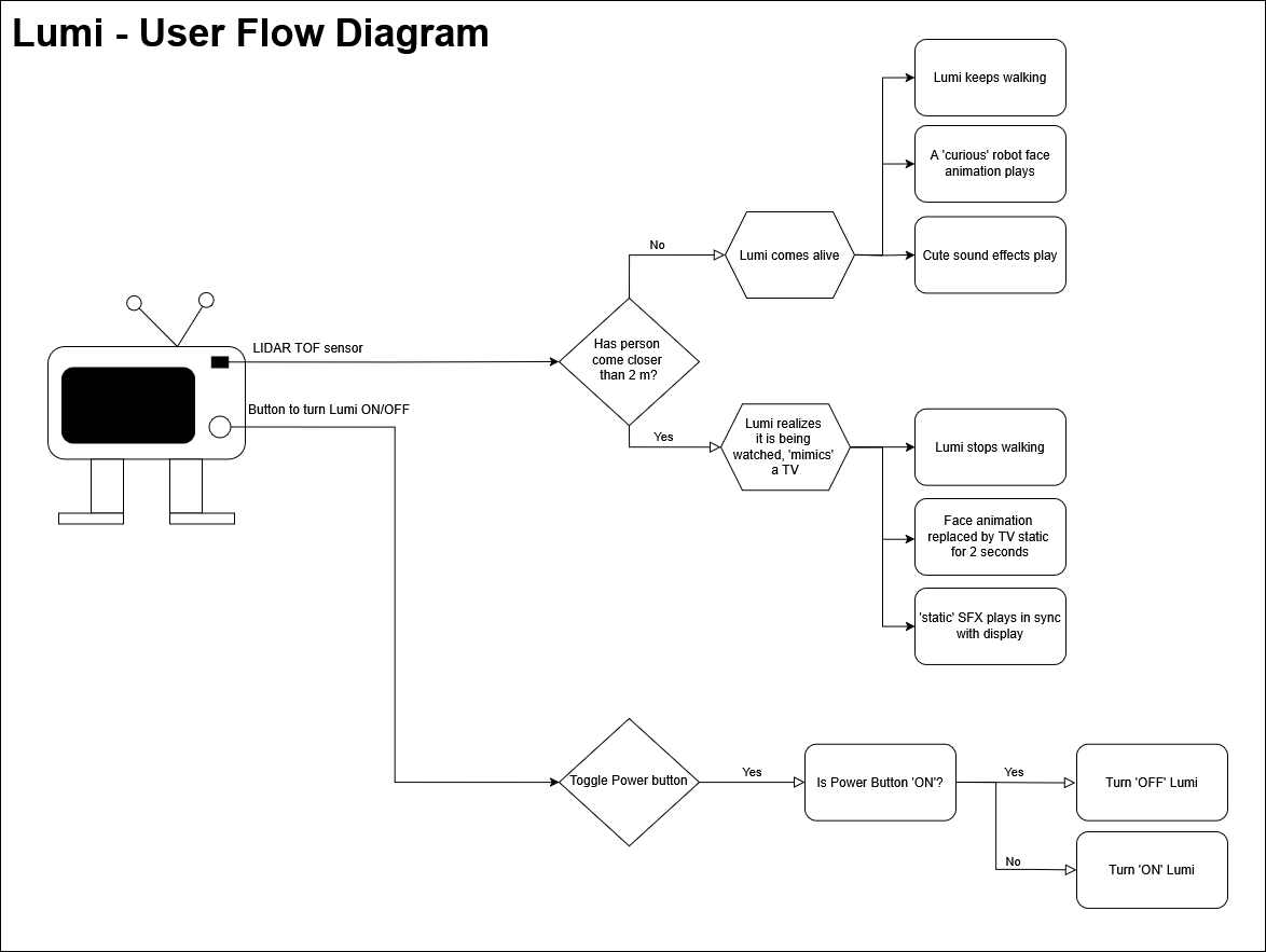
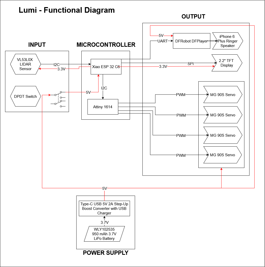
Click here to see the user flow diagram and functional flow diagrams answer these questions clearly.
Who's done what beforehand?
I will be using the following assets/files made by others to make my final project:
- There are multiple examples to make a mini TV display:
- How to Make a Retro Mini-TV! (by maker_soup, Instructables)The primary inspiration for the TV design
- ESP32 Mini TV Tutorial Build (Taylor Galbraith, Youtube): provided me a reference for playing TV video and audio
- Mini Retro TV(by 陳亮, Instructables): Provided extensive documentation for MicroSD card and MAX98357 audio requirements
- Working Miniature "Television" (By entomophile, Instructables): A twist on the original idea; convert an old media player into a miniature TV
- ESP32 Pinout Reference: Which GPIO pins should you use? (Randomnerdtutorials.com): Easy to follow documentation on ESP32 pinouts, which pins to avoid and which pins to use for different communication protocols
- Otto: The design of the legs that create the shuffle/dance are based off of an open source project called
What sources did you use?
Please see References section which answers this question.
What did you design?
- Integrating a TV into the Otto leg design
- PCB designing that uses an ESP32 chip instead of the DevKit
- The program logic that uses a TOF TOF TOF LiDAR as an input and servos, TFT display and audio as the output
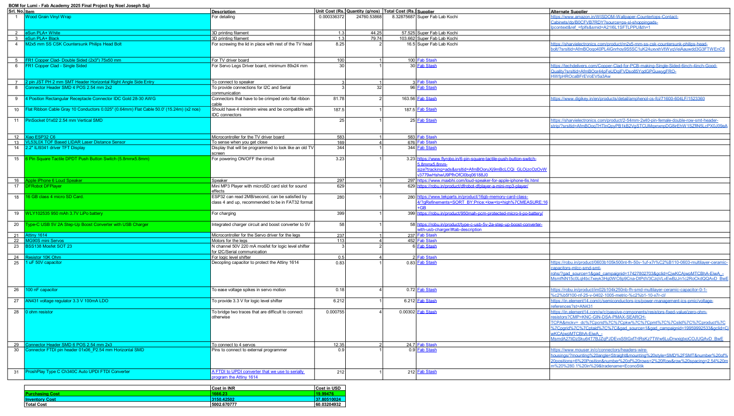
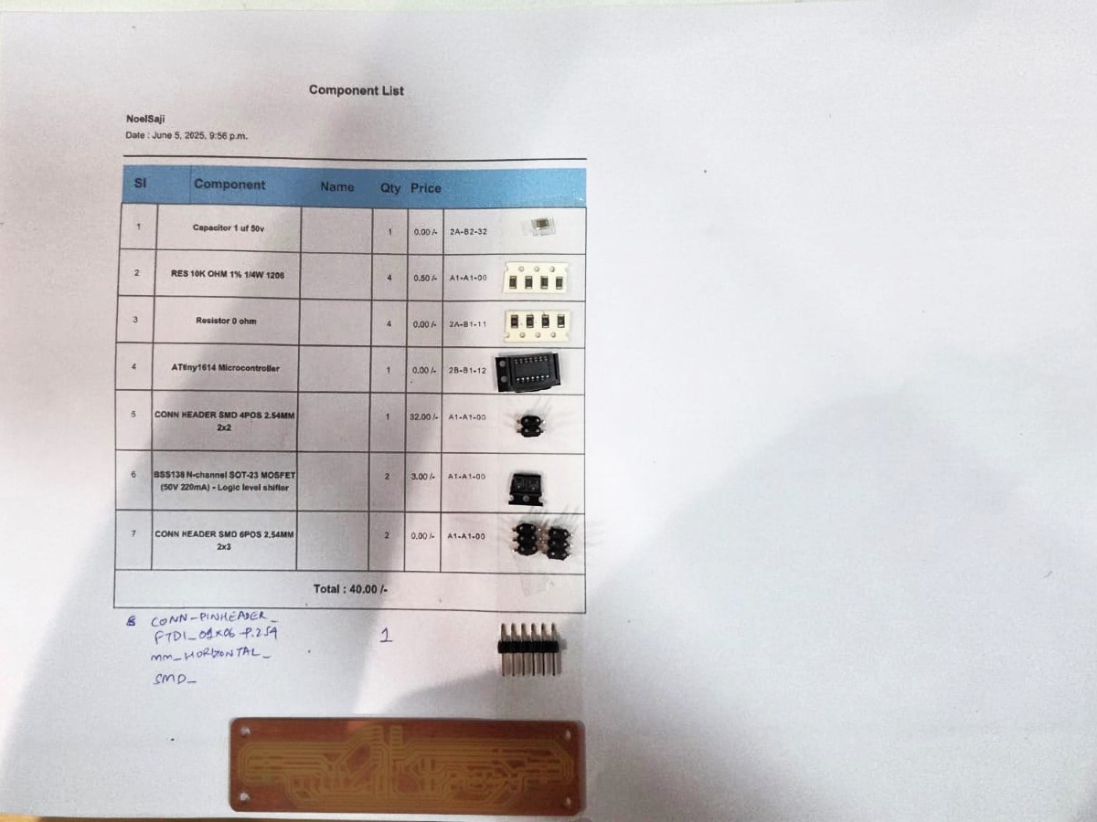
What materials and components will be used? Where will come from? How much will they cost?
All these questions have been answered in my BOM sheet
What parts and systems will be made?
- An easily assemblable and disaassemblable TV case
- Two PCBs holding different electronics and mounted behind the other using pin headers and pin sockets
- A modified leg design based on Otto's original design to accommodate the changed positioning of the servos
- A wood vinyl wrapper applied on top of the case to make the TV more realistic
What processes will be used?
I have used the following processes:
- Laser cutting - for initial prototyping in cardboard
- 3D printing - for making the outer body
- Vinyl cutting - to mimic a wood finish for the TV case
- PCB Designing - in KiCAD
- Milling - To make the PCB
- Soldering - To make the PCB
- Programming - In Arduino IDE & VS Code
What questions were answered?
-
Can kerf bending be used to create a laser cut wood frame for my TV?
No, the radius needs to be at least 15 mm for 3mm birch wood. Will remove this idea, instead replacing it with vinyl cut wrapper to mimic a wood finish
-
Library support for the ESP32/Xiao ESP32C6?
Yes, there were no issues with library support.
-
Can the all three functions, audio, video, and movement play in sync?
Right now there are some issues with getting all three functions at the same time. More investigation will be required
-
Does the entire animation flow make visual sense from an external user perspective?
The animations switches between 'TV' mode and 'alive' mode too quickly, there needs to be some delay
-
Since the TV will be more front heavy, that will affect the weight distribution. Will this cause the TV to fall? Will this issue be solved if the 'hip' servos are changed to offset the position of the legs
No such issues where found.
What worked? What didn't?
- Due to the difficulty in integrating electronics into my system, I had to drop the idea of an SD card reader that stores TV footage, so currently I am unable to play long duration TV footage.
- By the time of the final project presentation Lumi does not play TV footage
- While each function (audio, video, and movement) plays individually in response to TOF TOF LiDAR input, there are some issues in syncing the timing of all three. By the time of final presentations, it would only work sometimes
- Lumi 'moves', but does not walk properly. The logic behind servo control must be modified.
- Only one facial animation plays. The facial animations should be improved to increase the interactiveness.
- Right now the TOF TOF LiDAR sensor reacts to all objects, including non-human objects. This means that reflections from surfaces, especially white surfaces cause Lumi to switch erraticly between 'TV' and 'alive' mode.
- The button switch gets obstructed on the base of the buttons and the TOF TOF LiDAR enclosure. To make space, the part of the TOF TOF LiDAR enclosure that obstrcuts the button had to be cut.The tip of the button also had to be cut to reduce its overall height
- The clearance between the buttons and the button frame should be increased
- The mounting of the hip servos must be made easier. One idea is to redesign the TV head so that one can add screws from below the base of the TV head
- Currently, the goal of easy dissassembly has not been achieved. to replace the hip servos, the whole mechanism has to be dissassembled. Also it is very hard to remove the TV Driver PCB because the clearance is too small
- The locator pins/lip/flange at the bottom of the TV_Top should be extended farther. The vinyl wrapper adds thickness which reduces the usefulness of the locator pins
- There is no visual indication of charging status, which needs improvement
- A debugging/power LED on the servo legs PCB would have been a good touch to improve debugging experience
- The speaker mounting method should be improved, at one point, the speaker would start sliding through and obstructing the servo legs.
By the time of final presentations
How will it be evaluated?
Does Lumi respond in any way to input from the TOF TOF LiDAR sensor? Yes
Your project should incorporate:
- 2D and 3D design ✔
- additive and subtractive fabrication processes ✔
- electronics design and production ✔
- embedded microcontroller interfacing and programming ✔
- system integration and packaging ✔
What are the implications?
Lasercutting a Mockup in Cardboard
To get a better idea of the form of my final project, I prepared a design to lasercut a mockup design of my final project. For the legs I used the help of Boxes.py. I even tried arranging the servos and the TFT display to get a better idea of the space I would need inside the enclosure, what I called the TV Head
User Flow and Functional Flow
During System Integration Week I made a system diagrams for user flow and function flow based on instructions from our instructor. This helped us in finalising all the electronics that would be used.
Project Development
Click here to see my project development page.
Testing
I had spent time to test various parts of my project at different points in time
Testing the TFT Display
I tested the refresh rate of the TFT display using an example Arduino sketch
Speaker Testing
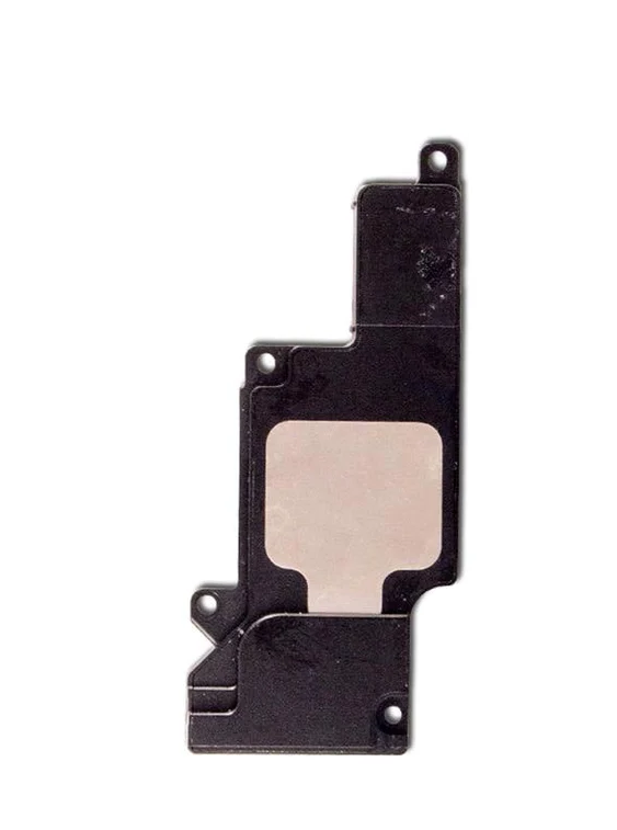
I was able to successfully test the functioning of the SD card player with the MAX98357A audio amplifer and the iPhone 6 Plus speaker with the help of Revi's code
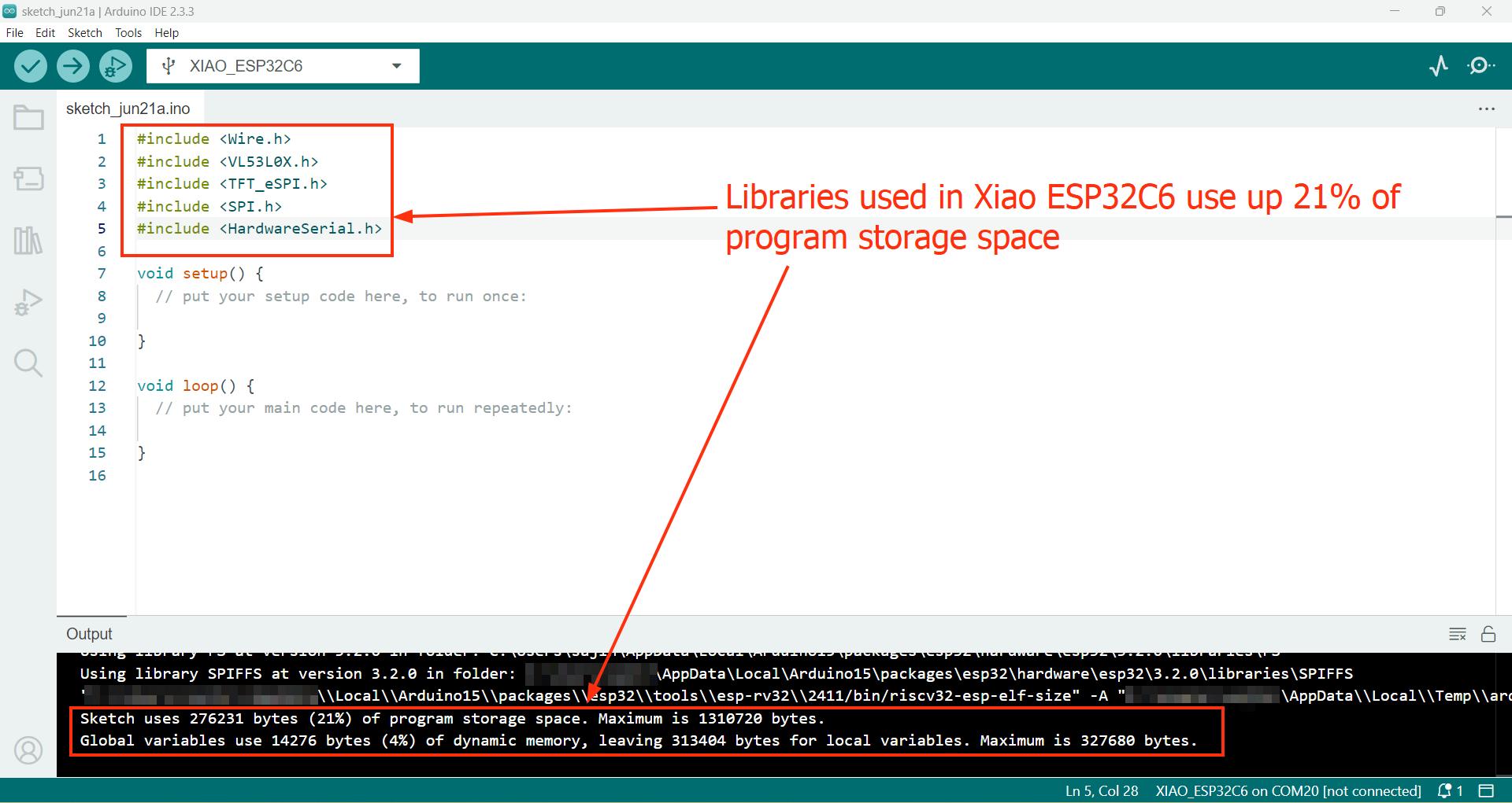
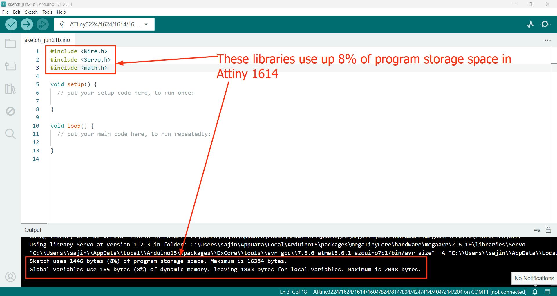
Testing Library Support
Based on my instructor's advice I tested the library support for the Xiao ESP32 C6 and Attiny 1614. It is also important to check how much program storage space is being taken up by these libraries, since they decide how much memory can be allotted to programming.
Testing the Walking Mechanism
I downloaded the STEP files of OTTO and used that as a reference to design my walking mechanism in Fusion, accommodating for changes in:
- the servo mount height
- the size of the servo horns
- changed position of the servos
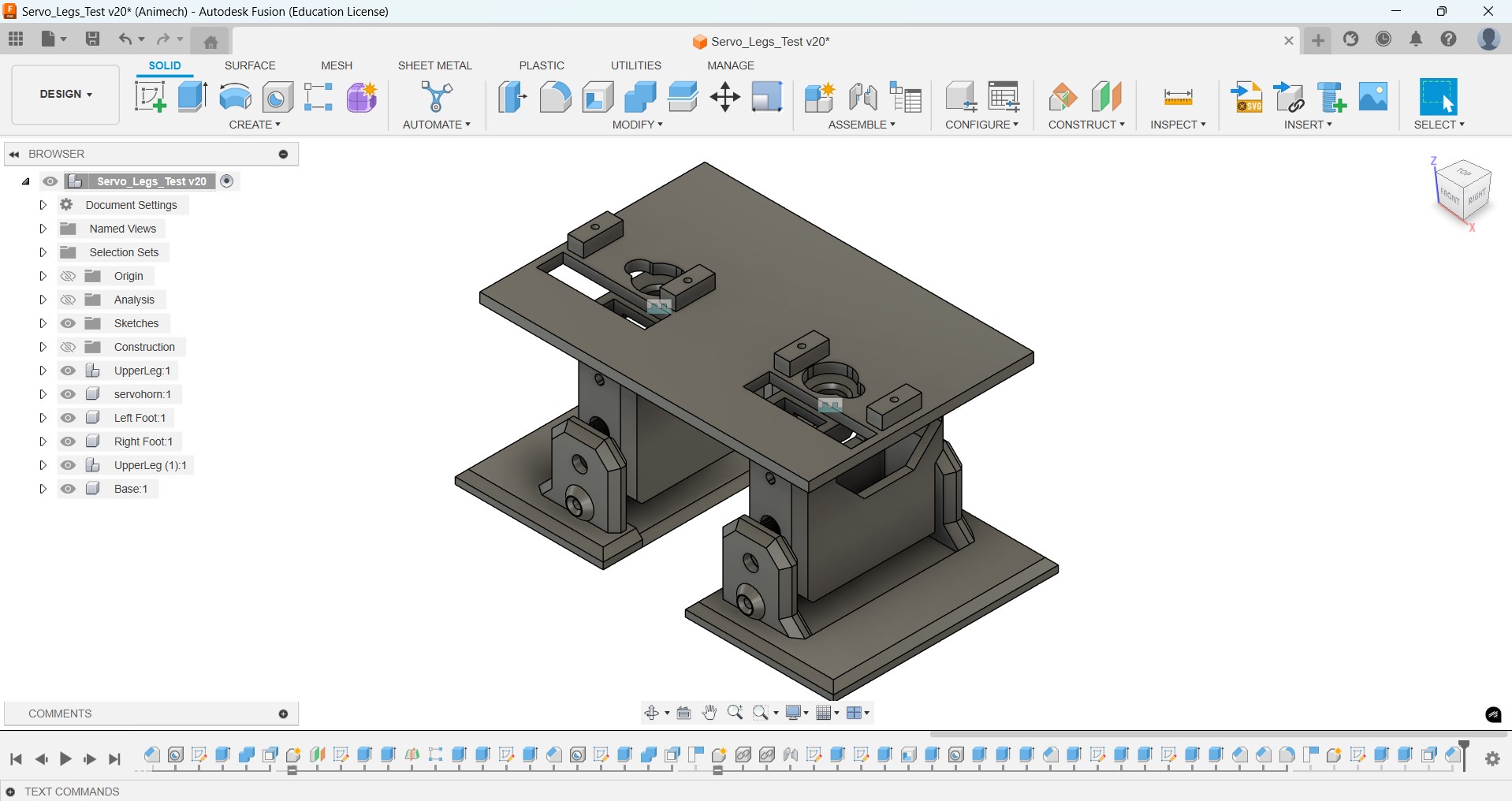
I tested the mechanism using a breaboard and a Xiao ESP32 since I did not have a dedicated PCB made for this at the time
Computer Aided Design
Since I already designed the walking mechanism before, I now focused on designing the enclosure called TV Head
Enclosure Design
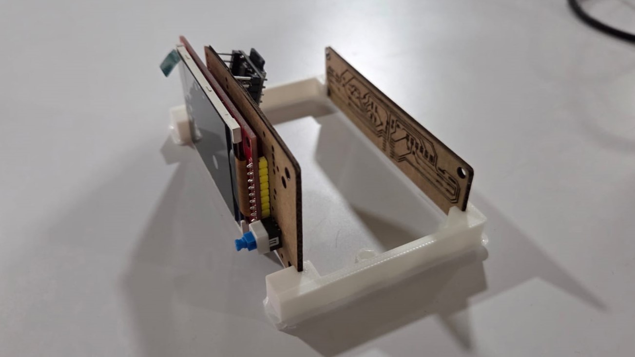
I tested how the battery could fit in between the servos using a base I had made while prototyping the walking mechanism for Lumi
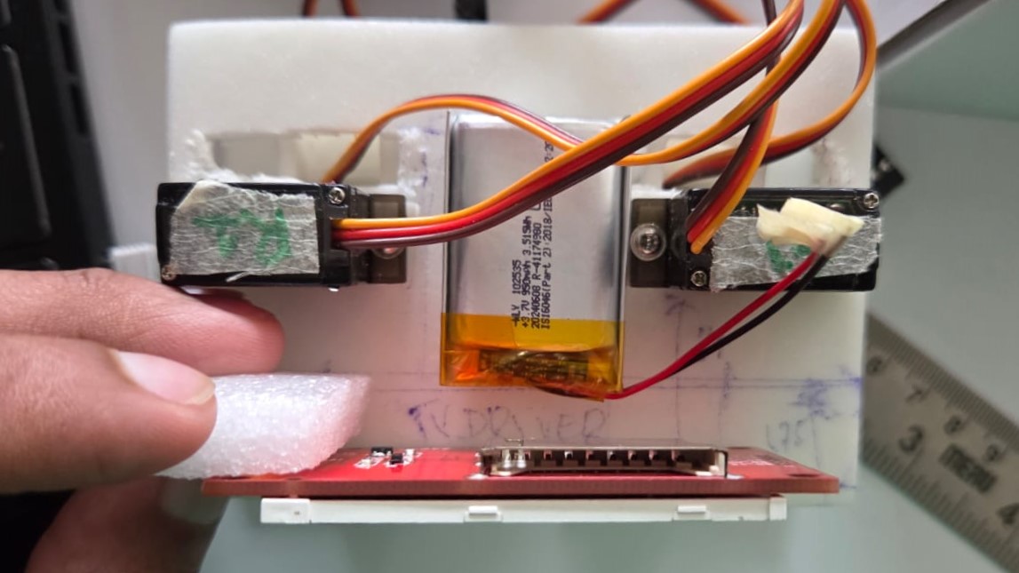
I tested how the PCBs could fit without fasteners using a mechanism similar to a drawer slide.
My design has evolved a lot from the initial idea at the start of Fab Academy.
This video shows the electronic placement in Fusion
Final Render
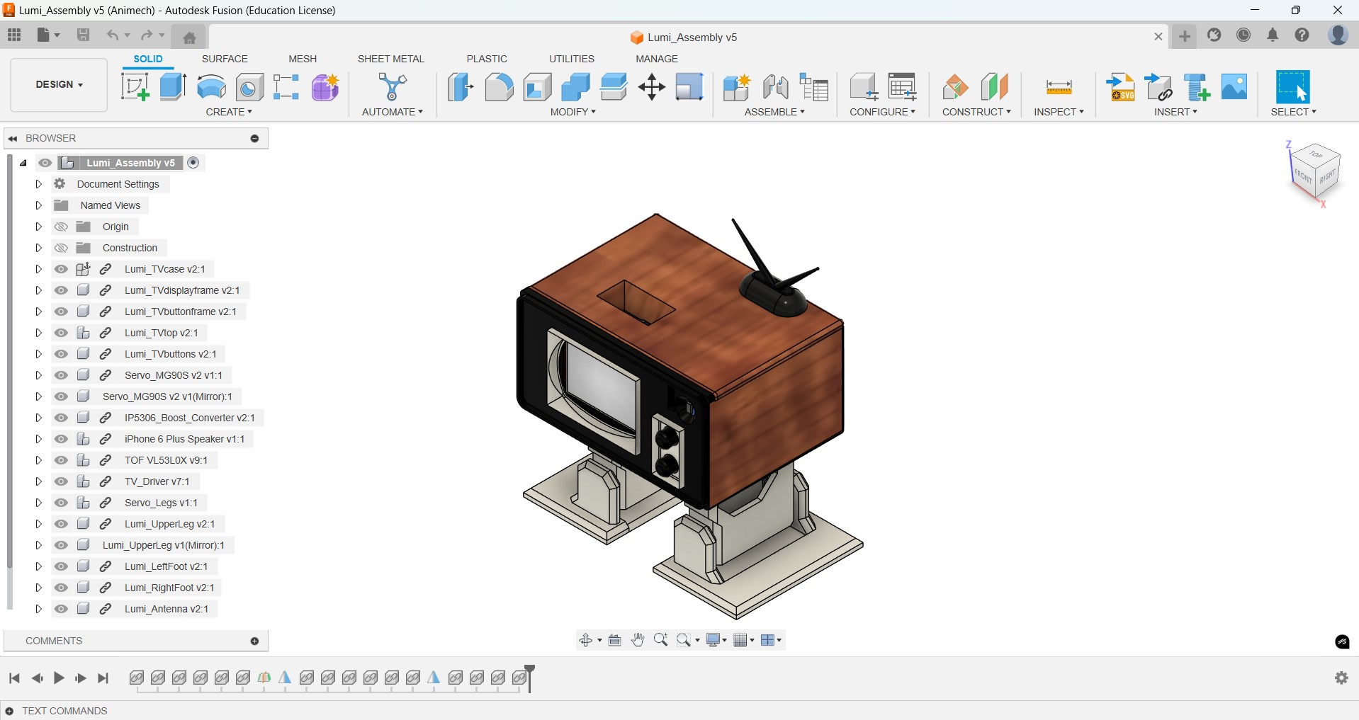
This is a render of the full assembly in Fusion
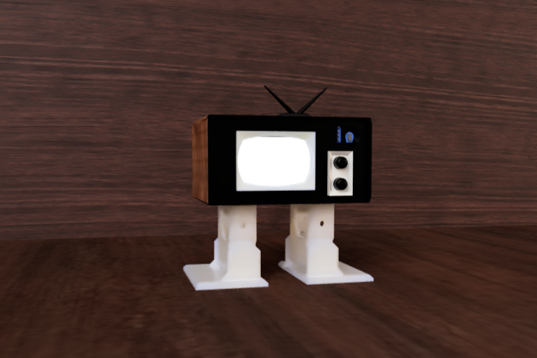
This is my model uploaded in Sketchfab
PCB Design
I designed and produced two different PCBs for my project, not including an external FTDI to UART converter I used for programming the Attiny 1614
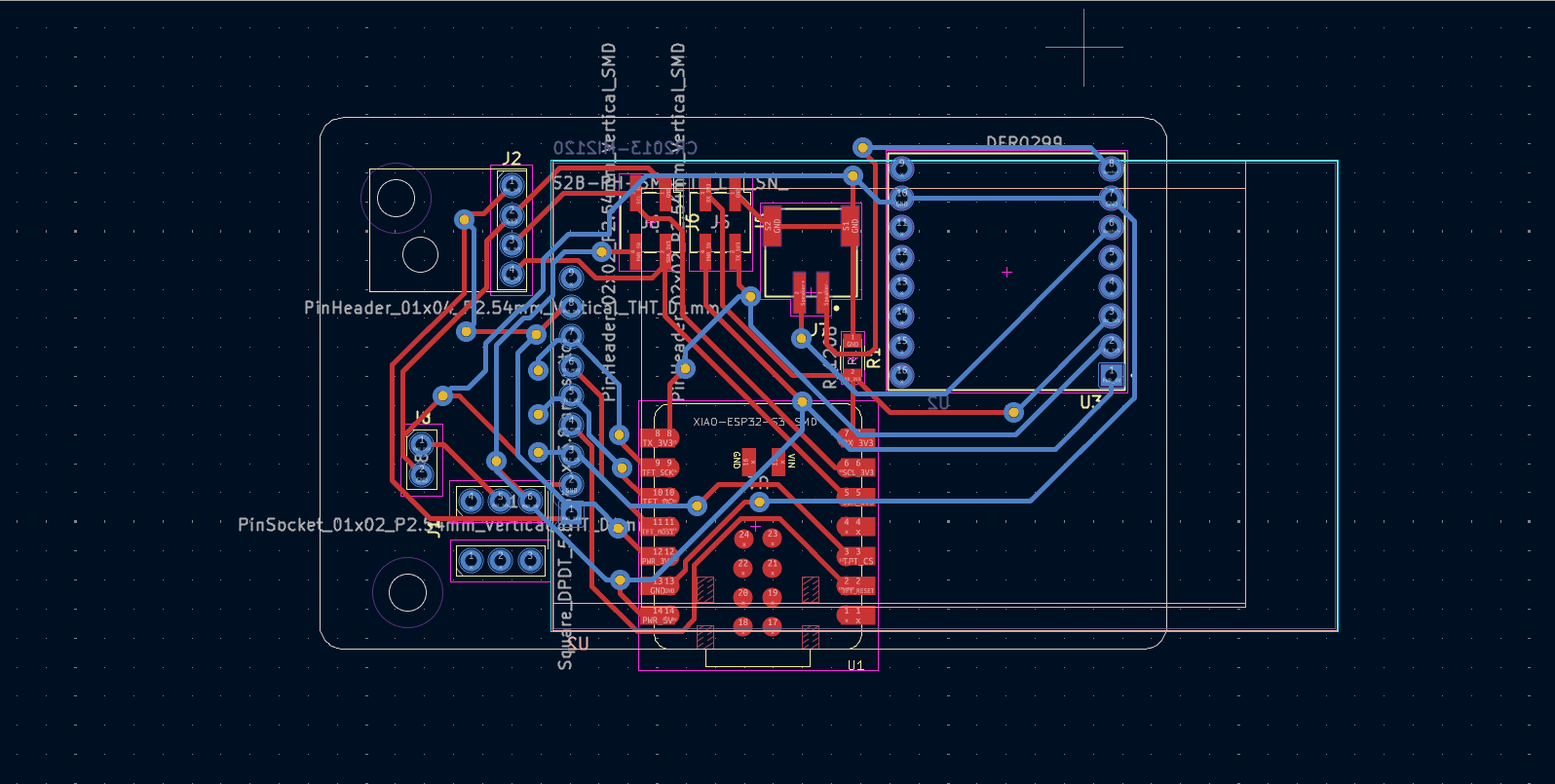
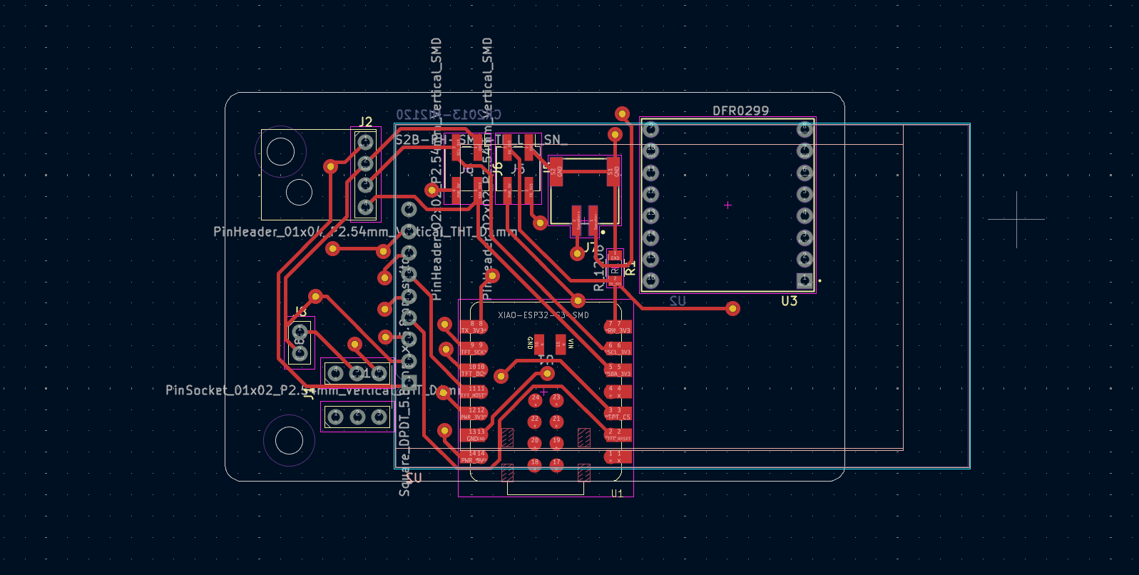
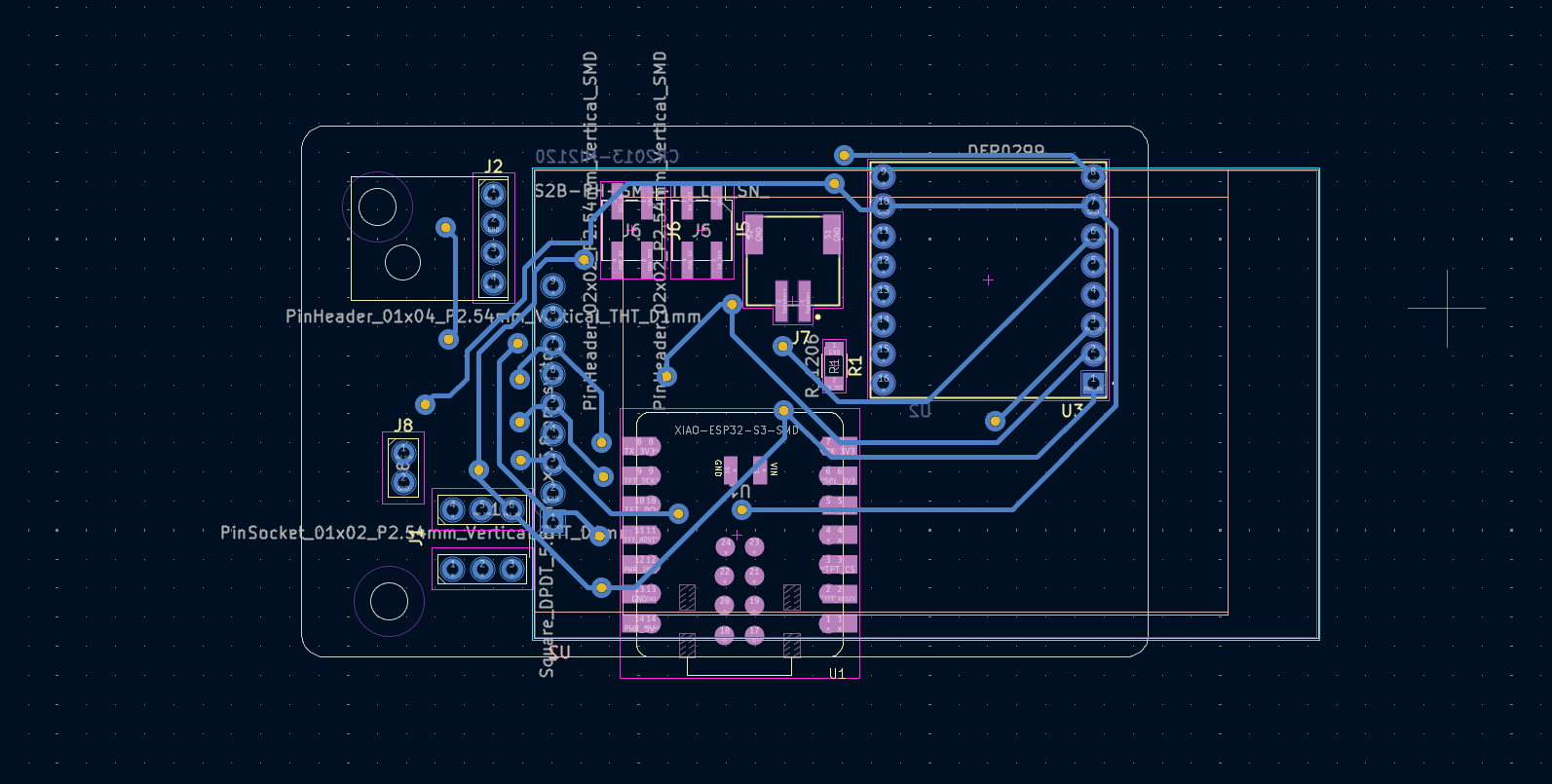
TV Driver Board
This is the TV Driver board I made which includes the master microcontroller, which is the Xiao ESP32 C6 and most of the connections to other electronics except to the servos.
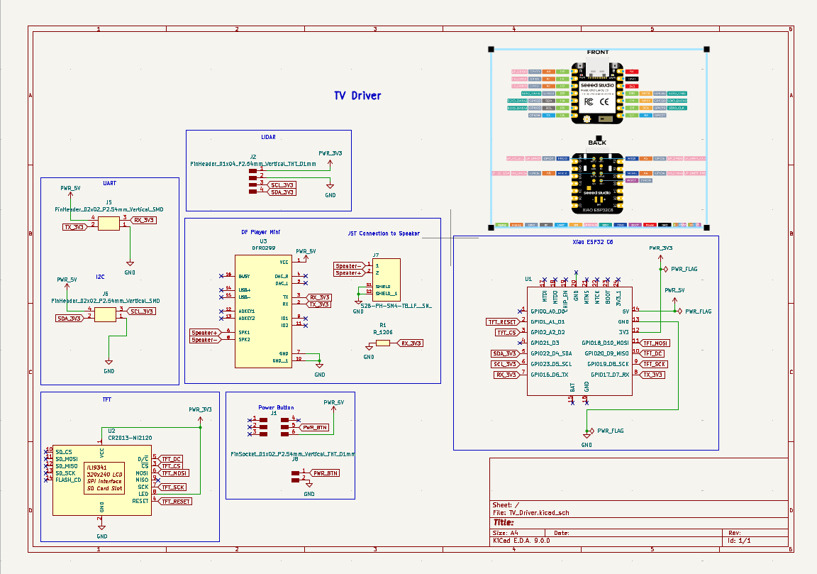
To this board we had made some corrections:
- The DFPlayer Mini’s serial pins (TX, RX) were connected to free GPIO pins (GPIO 0 and 21 in my case). The default serial pins are already used for communication between the Servo Legs Driver and TV Driver boards.
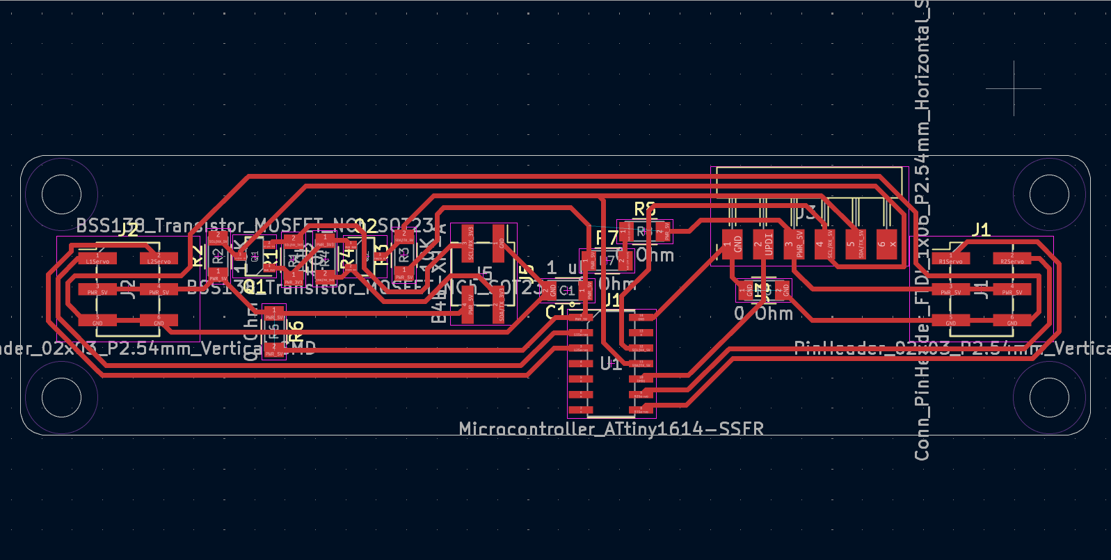
Servo Legs Driver
This is the Servo Legs driver, powered by an Attiny 1614 acting as a node communicating via I2C with the Xiao ESP32 in the TV Driver board
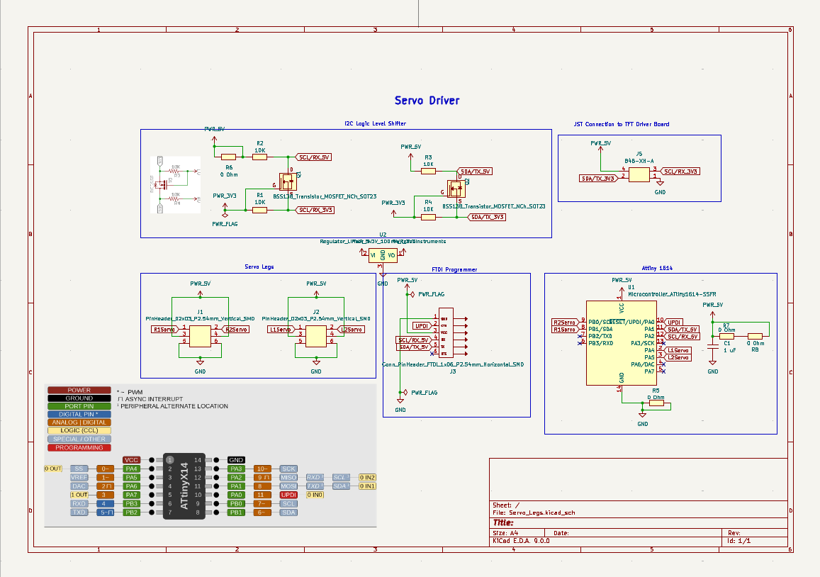
To this board we had made some corrections:
- I didn’t have any 3.3V pinouts on the Servo Legs Driver PCB, so I added a small 3.3V 100mA voltage regulator to convert 5V (VIN)to 3.3V (VOUT) and third terminal to GND. This is needed for the logic level shifter to work properly.
- We used the ProshPlay Type C CH340C Auto UPDI FTDI Converter to program and read data from the Attiny1614. But with the current design, I2C communication won’t work when the boards are connected, since SDA and SCL share the same pins as TX and RX. To fix this, I cut the FTDI TX/RX connections and rerouted them to PB2 and PB3.
- Additionally we added 4 100 nF decoupling capacitors to ease voltage spikes from servos while drawing current
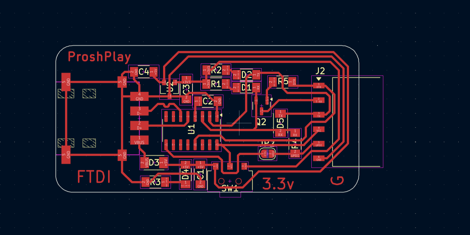
Attiny 1614 Programmer
To program and debug the Servo Legs PCB, I also produced and used the ProshPlay Type C CH340C Auto UPDI FTDI Converter designed by our instructor Saheen Palayi
Making the TV Head
3DPrinting
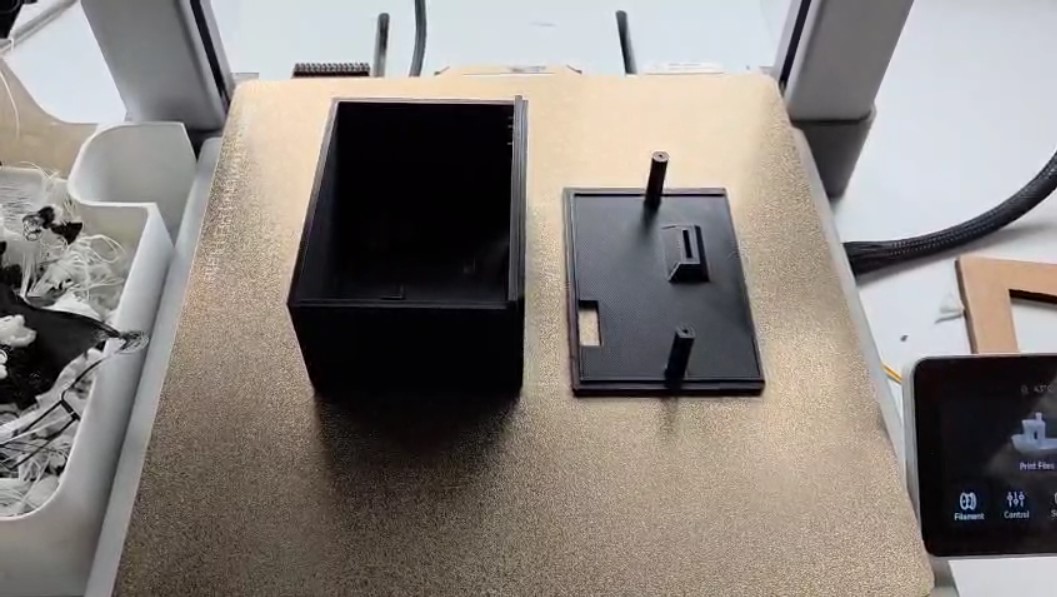
I 3D printed the outer case and buttons in black and the inner frames in white to provide some contrast and match with the white of the legs
Vinyl Cutting
For detailing I used a wood grain vinyl sheet to wrap the TV Head enclosure
Assembly
In addition figured out the placement of all the electronics in CAD software housing in CAD software. A possible improvement of the current design is to work on wire management.
Programming
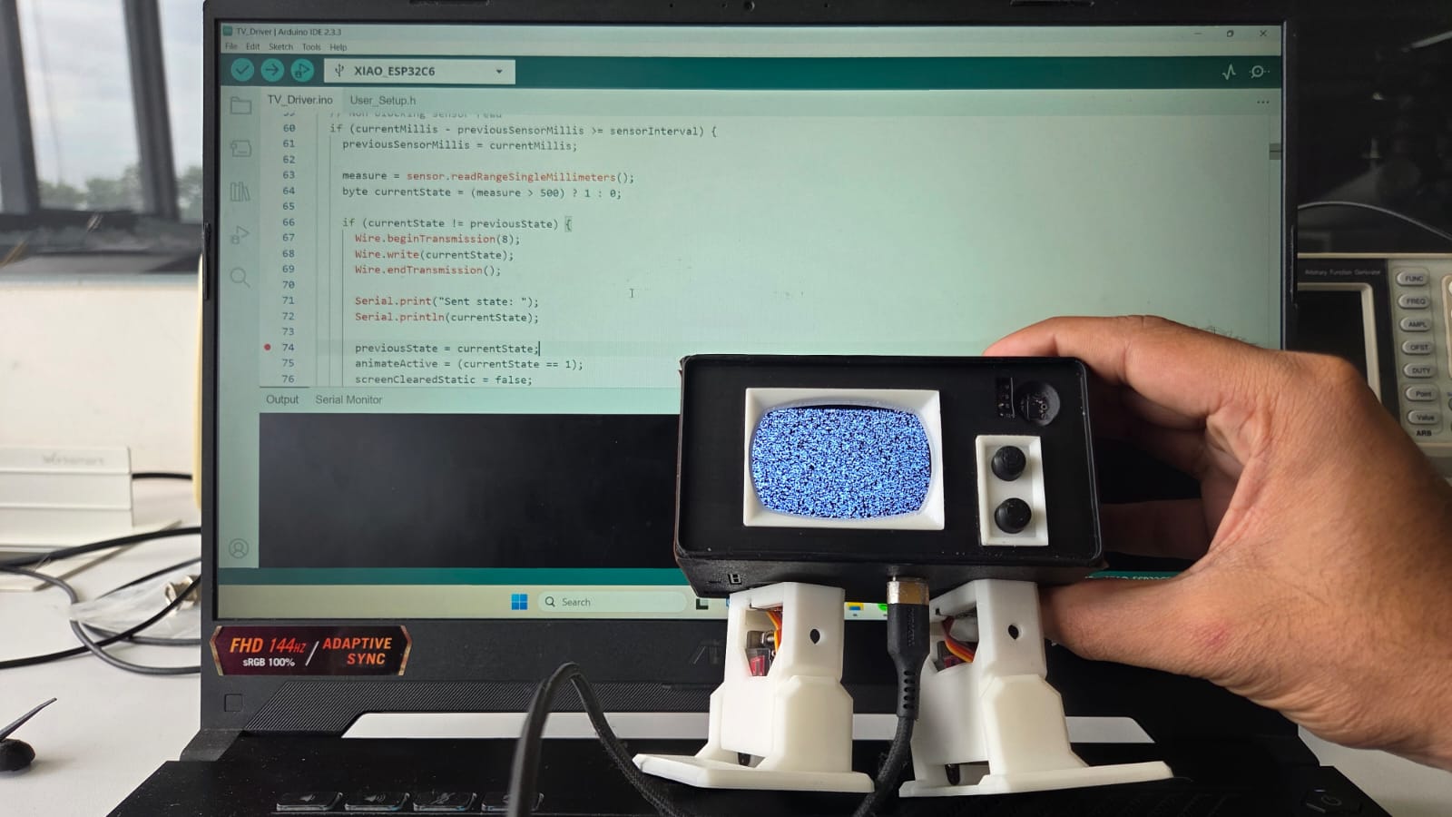
I used Arduino IDE to program Lumi. As you can see I can plug a USB-C cable directly underneath into the USB-C socket of the Xiao ESP32 C6 to program the TV driver board
Programming the TV Driver
  #include <Wire.h>
  #include <VL53L0X.h>
  #include <TFT_eSPI.h>
  #include <SPI.h>
  #include <HardwareSerial.h>

  // DFPlayer Serial Pins
  #define DF_RX D3
  #define DF_TX D0

  HardwareSerial mySerial(1); // Use UART1

  // Global objects
  VL53L0X sensor;
  TFT_eSPI tft = TFT_eSPI();

  // State variables
  int measure;
  byte previousState = 0;
  bool animateActive = true;
  bool screenClearedStatic = false;
  bool screenClearedAnimation = false;
  bool staticSoundPlayed = false;
  bool animationSoundPlayed = false;

  // Animation variables
  int mouthFrame = 0;
  unsigned long previousMouthMillis = 0;
  unsigned long mouthInterval = 50;

  // Sensor timing
  unsigned long previousSensorMillis = 0;
  const unsigned long sensorInterval = 100;

  void setup() {
  Serial.begin(115200);
  mySerial.begin(9600, SERIAL_8N1, DF_RX, DF_TX);
  Serial.println("DFPlayer ready (raw serial)");

  Wire.begin();
  sensor.setTimeout(500);
  if (!sensor.init()) {
    Serial.println("Failed to detect and initialize sensor!");
    while (1);
  }

  tft.init();
  tft.setRotation(1);
  tft.fillScreen(TFT_BLACK);
  Serial.println("Display ready!");

  setVolume(20); // Set volume between 0-30
  delay(2000);
  }

  void loop() {
  unsigned long currentMillis = millis();

  // Non-blocking sensor read
  if (currentMillis - previousSensorMillis >= sensorInterval) {
    previousSensorMillis = currentMillis;

    measure = sensor.readRangeSingleMillimeters();
    byte currentState = (measure > 500) ? 1 : 0;

    if (currentState != previousState) {
      Wire.beginTransmission(8);
      Wire.write(currentState);
      Wire.endTransmission();

      Serial.print("Sent state: ");
      Serial.println(currentState);

      previousState = currentState;
      animateActive = (currentState == 1);
      screenClearedStatic = false;
      screenClearedAnimation = false;
      staticSoundPlayed = false;
      animationSoundPlayed = false;
    }
  }

  if (animateActive) {
    if (!screenClearedAnimation) {
      tft.fillScreen(TFT_BLACK);
      screenClearedAnimation = true;
    }
    if (!animationSoundPlayed) {
      playTrack(2);  // Play Track 2 for animation
      animationSoundPlayed = true;
    }
    updateMouthAnimation();
  } else {
    if (!screenClearedStatic) {
      tft.fillScreen(TFT_BLACK);
      footagestatic();
      screenClearedStatic = true;
    }
    if (!staticSoundPlayed) {
      playTrack(1); // Play Track 1 for static screen
      staticSoundPlayed = true;
    }
  }
  }

  void updateMouthAnimation() {
  unsigned long currentMillis = millis();

  if (currentMillis - previousMouthMillis >= mouthInterval) {
    previousMouthMillis = currentMillis;

    tft.fillRect(136, 150, 40, 50, TFT_BLACK);
    tft.fillEllipse(193, 112, 22, 40, 0xFFFF);
    tft.fillEllipse(122, 113, 22, 40, 0xFFFF);

    int Ypos[] = { 164, 171, 177 };
    int Ysize[] = { 7, 14, 20 };
    tft.fillEllipse(156, Ypos[mouthFrame], 18, Ysize[mouthFrame], 0xFFFF);

    mouthFrame = (mouthFrame + 1) % 3;
    mouthInterval = random(50, 150);
  }
  }

  void footagestatic() {
  static const unsigned char PROGMEM image_arrow_curved_left_down_up_bits[] = { 0x20, 0x60, 0xf8, 0x6c, 0x22 };

  static const unsigned char PROGMEM image_Static_3_bits[] = { 0x06, 0x30, 0x49, 0x10, 0x00, 0x00, 0xc4, 0x03, 0x03, 0x41, 0x01, 0xd0, 0x05, 0xfe, 0x02, 0x21, 0x00, 0xd4, 0x6b, 0x86, 0x01, 0x44, 0x00, 0x02, 0x00, 0x80, 0x16, 0x04, 0x06, 0x14, 0x06, 0x00, 0x05, 0x00, 0x37, 0x03, 0xe3, 0x00, 0x3c, 0x00, 0x00, 0xa0, 0x00, 0x30, 0x00, 0x04, 0xc0, 0x11, 0x0f, 0x88, 0x88, 0x01, 0x63, 0x06, 0x08, 0x71, 0x06, 0xec, 0xff, 0x2b, 0x10, 0x22, 0x1e, 0x68, 0x15, 0x8c, 0x0c, 0x44, 0x04, 0x00, 0x40, 0x18, 0x06, 0x34, 0x10, 0x30, 0x00, 0x02, 0x28, 0x00, 0x00, 0x80, 0x02, 0x21, 0x90, 0x70, 0x00, 0xc2, 0x58, 0x70, 0x20, 0x01, 0x03, 0x96, 0x6c, 0x58, 0x02, 0xe7, 0xff, 0x38, 0xd0, 0x03, 0x74, 0xdc, 0x88, 0x06, 0xa0, 0x50, 0x06, 0x08, 0x80, 0x00, 0x02, 0x30, 0x0c, 0x90, 0x20, 0x12, 0x00, 0x07, 0x01, 0x91, 0x0f, 0x80, 0x30, 0x00, 0xdd, 0xe6, 0x2c, 0x3a, 0x61, 0x10, 0x0e, 0xbf, 0xbe, 0x28, 0x88, 0xbe, 0xee, 0x40, 0x56, 0x6f, 0xcd, 0x85, 0x8a, 0x01, 0xe0, 0x7c, 0x0f, 0x0d, 0x84, 0x00, 0x02, 0x30, 0x07, 0x00, 0x93, 0x8e, 0x00, 0x7f, 0xde, 0x1e, 0x40, 0x20, 0x70, 0x00, 0x7f, 0xfb, 0x1d, 0x10, 0xd3, 0x1e, 0x3c, 0x01, 0x81, 0x18, 0x02, 0x4c, 0xd1, 0x04, 0x0a, 0x26, 0x45, 0x03, 0xef, 0x80, 0x89, 0x07, 0xff, 0x00, 0xf3, 0x1c, 0x40, 0x20, 0x38, 0x00, 0x80, 0xc7, 0xf0, 0x42, 0x71, 0x00, 0x48, 0x64, 0x02, 0x04, 0x55, 0x78, 0x04, 0x90, 0x01, 0x4c, 0x3c, 0x20, 0x05, 0x14, 0x04, 0x48, 0x41, 0x1a, 0x40, 0x00, 0x00, 0x01, 0x04, 0x04, 0x0c, 0x11, 0xc0, 0x12, 0x7c, 0x1d, 0x00, 0x00, 0x00, 0x42, 0x80, 0xc7, 0x10, 0x02, 0x31, 0x80, 0x08, 0x20, 0x80, 0xa8, 0x00, 0x00, 0x00, 0xf1, 0xa1, 0x80, 0x2d, 0xc1, 0x74, 0xaf, 0x04, 0x00, 0x20, 0xc8, 0x71, 0xe4, 0x0c, 0x32, 0x1e, 0x10, 0x25, 0x0c, 0x22, 0x10, 0x40, 0x55, 0x90, 0x01, 0x81, 0x00, 0x00, 0x03, 0x01, 0xfa, 0x18, 0xf5, 0x0f, 0x18, 0x00, 0xf8, 0x80, 0x00, 0x00, 0xbc, 0x80, 0x01, 0x0f, 0xd1, 0x70, 0x1f, 0xe8, 0x60, 0x00, 0xc8, 0x60, 0x04, 0x1a, 0x02, 0x08, 0xf3, 0x06, 0x86, 0x02, 0xb0, 0x41, 0xf3, 0x73, 0xc0, 0x87, 0x80, 0x00, 0x04, 0x89, 0x20, 0x00, 0x19, 0x48, 0x10, 0x01, 0xe7, 0x95, 0x87, 0xdc, 0x1e, 0x00, 0x11, 0xf9, 0x82, 0x31, 0x0f, 0x98, 0x00, 0x00, 0x00, 0x20, 0x09, 0x5b, 0x87, 0x88, 0x7f, 0xbe, 0x17, 0x86, 0x1a, 0x19, 0xb8, 0x18, 0x80, 0x08, 0x00, 0x00, 0x00, 0x14, 0x02, 0x01, 0x00, 0x88, 0x10, 0x00, 0x23, 0xbf, 0x87, 0xc4, 0x07, 0x00, 0x00, 0x3c, 0x28, 0x01, 0x0d, 0x18, 0x00, 0x48, 0x80, 0x00, 0x9f, 0xd3, 0x00, 0xc8, 0x92, 0x59, 0xc0, 0x52, 0x03, 0x51, 0x80, 0x20, 0x1b, 0x28, 0x20, 0x06, 0x02, 0x10, 0x25, 0x4d, 0x60, 0x0c, 0x70, 0x7e, 0x6f, 0x00, 0x74, 0x08, 0x87, 0xe0, 0x80, 0x36, 0x78, 0x01, 0xdc, 0x10, 0x01, 0x8e, 0xc0, 0xa0, 0x00, 0x07, 0x80, 0x00, 0x04, 0x01, 0x45, 0x60, 0x23, 0x11, 0x84, 0x23, 0x7f, 0xf0, 0xff, 0x1c, 0x03, 0x20, 0x4c, 0xe0, 0x60, 0x89, 0xc0, 0x06, 0xab, 0x20, 0x24, 0x08, 0x88, 0xf0, 0x88, 0x71, 0xf3, 0x3c, 0xc2, 0x23, 0x00, 0x10, 0x70, 0x20, 0xc0, 0x02, 0x40, 0x00, 0x0c, 0x00, 0x17, 0xc4, 0x30, 0x11, 0xd0, 0x3b, 0x80, 0x34, 0x00, 0x07, 0x0e, 0x8a, 0x3f, 0xc0, 0x00, 0x35, 0x40, 0x04, 0xe8, 0x60, 0x04, 0x38, 0xf8, 0x30, 0x11, 0xe2, 0x00, 0x08, 0x41, 0x17, 0x60, 0x78, 0x70, 0x02, 0x85, 0x10, 0x00, 0x58, 0x40, 0x00, 0x41, 0x0f, 0x02, 0x40, 0x0d, 0xb8, 0x44, 0x40, 0x0e, 0x03, 0x13, 0x8e, 0x20, 0x40, 0x00, 0x4c, 0x00, 0x00, 0x00, 0x20, 0x4c, 0x9c, 0x1c, 0x24, 0x20, 0xf2, 0x80, 0x00, 0xc8, 0x94, 0x73, 0x7b, 0x91, 0x02, 0x04, 0x86, 0xe4, 0x31, 0xf8, 0x24, 0x0d, 0x3c, 0x0a, 0x40, 0x07, 0xd8, 0x24, 0x00, 0x92, 0x81, 0xa0, 0xe2, 0x00, 0x20, 0x11, 0x48, 0x50, 0x21, 0xb0, 0x01, 0x80, 0x0e, 0x38, 0x30, 0xe0, 0x21, 0x41, 0x20, 0x80, 0x07, 0x00, 0x01, 0x0d, 0xf8, 0x7c, 0x86, 0x10, 0xc3, 0x00, 0x34, 0x06, 0x2c, 0x0a, 0x74, 0x33, 0x4c, 0x10, 0x3c, 0x00, 0x40, 0x10, 0x01, 0xd1, 0x04, 0x02, 0xfa, 0x48, 0x08, 0x00, 0x02, 0x00, 0x12, 0xb8, 0x01, 0xf0, 0x04, 0x11, 0xe4, 0x81, 0xc0, 0x00, 0xab, 0x0f, 0x9d, 0x1c, 0x85, 0x10, 0x8f, 0x82, 0x18, 0x03, 0xc6, 0x00, 0xa3, 0x28, 0x90, 0x00, 0x7f, 0x03, 0x03, 0x90, 0x00, 0x43, 0x40, 0x00, 0x40, 0x20, 0x1c, 0x0c, 0x02, 0x03, 0x90, 0x01, 0x82, 0x32, 0xe1, 0x10, 0x7e, 0x80, 0xe9, 0x00, 0x3e, 0x19, 0x14, 0x1c, 0xe1, 0x10, 0x07, 0xd9, 0xe0, 0x78, 0x43, 0x04, 0x04, 0xa0, 0x1a, 0x00, 0x06, 0x02, 0x12, 0x41, 0x80, 0x42, 0x01, 0x08, 0x00, 0x00, 0x54, 0xdc, 0x41, 0x80, 0x5b, 0x00, 0xc0, 0xb2, 0x13, 0xb0, 0x7e, 0x00, 0x7b, 0x82, 0x2e, 0x10, 0x30, 0xb0, 0x63, 0x01, 0x4f, 0x02, 0x00, 0x20, 0x41, 0x9e, 0x44, 0x62, 0x58, 0x00, 0x04, 0x08, 0x0c, 0x23, 0xd8, 0x70, 0x09, 0xf1, 0x86, 0x9e, 0x11, 0x98, 0xc4, 0x1a, 0x1f, 0x8a, 0xe2, 0x93, 0x1f, 0xf0, 0x7c, 0x71, 0x0b, 0xc7, 0xe6, 0x81, 0xee, 0x01, 0x11, 0x08, 0x47, 0x0a, 0x04, 0x21, 0xd9, 0x91, 0xee, 0x77, 0xf8, 0x70, 0xf0, 0x11, 0x0f, 0xb2, 0x1d, 0x49, 0x47, 0x10, 0x33, 0x43, 0xd1, 0x88, 0xb4, 0x11, 0x1c, 0x7e, 0x47, 0x1f, 0xfc, 0x30, 0x00, 0x41, 0xa0, 0x00, 0x02, 0x00, 0x26, 0x00, 0x15, 0x0c, 0x62, 0x08, 0x80, 0x08, 0xdf, 0xc0, 0x43, 0x03, 0x26, 0x00, 0x1f, 0x00, 0xcc, 0x88, 0xc0, 0x82, 0xf4, 0x04, 0x08, 0x02, 0x01, 0x04, 0x30, 0x60, 0x18, 0x70, 0x00, 0x2c, 0x10, 0x00, 0x03, 0x63, 0xc0, 0x10, 0x00, 0x00, 0x30, 0x7e, 0xc4, 0x3f, 0x88, 0x0e, 0xc0, 0x3a, 0xdd, 0x4c, 0xf9, 0x9e, 0x00, 0x00, 0x0e, 0x00, 0xc8, 0x08, 0x80, 0x82, 0xbc, 0x06, 0x80, 0x02, 0x00, 0x10, 0x88, 0xe6, 0x1e, 0xc4, 0xea, 0x00, 0x80, 0x00, 0x2b, 0x72, 0xc0, 0xde, 0x00, 0x02, 0x0e, 0xe0, 0x20, 0x7e, 0x38, 0x0e, 0x24, 0x1d, 0x4a, 0x3f, 0xe8, 0x5e, 0x10, 0xf3, 0x96, 0xc0, 0x00, 0x20, 0x63, 0x09, 0x6a, 0x17, 0xe4, 0x76, 0x00, 0xbd, 0xcf, 0xc3, 0x39, 0xcf, 0xa8, 0xc0, 0x80, 0x00, 0xe0, 0x48, 0x40, 0xc4, 0x10, 0xf2, 0xad, 0x84, 0x20, 0x3e, 0x28, 0x4a, 0x34, 0x41, 0x06, 0x3f, 0xe0, 0x06, 0xf9, 0xc3, 0x12, 0x02, 0x90, 0x42, 0x20, 0x08, 0x60, 0x1f, 0xc1, 0x34, 0x50, 0x1f, 0xcb, 0xcb, 0xe8, 0x55, 0xe8, 0x68, 0x1f, 0x01, 0x04, 0x42, 0x00, 0x64, 0x00, 0x62, 0xa4, 0x05, 0xe0, 0x3c, 0x01, 0x20, 0x01, 0xf1, 0xff, 0x1b, 0x30, 0x10, 0xca, 0x82, 0x00, 0x01, 0x90, 0x40, 0x10, 0x08, 0xe0, 0x43, 0xe1, 0x14, 0x22, 0x3f, 0x47, 0xfe, 0xe4, 0x00, 0x60, 0x16, 0x07, 0x30, 0x0e, 0x51, 0x06, 0x76, 0x00, 0x02, 0x20, 0x02, 0x0c, 0xfc, 0x91, 0x5e, 0x83, 0x61, 0xf8, 0x08, 0x01, 0x38, 0x04, 0x04, 0x20, 0xc0, 0xc0, 0x18, 0x1f, 0x7f, 0x20, 0x22, 0x31, 0x1c, 0x00, 0x77, 0x06, 0xc6, 0x10, 0x05, 0x00, 0x00, 0x8a, 0x30, 0x3e, 0x70, 0xe3, 0xdf, 0xfe, 0x46, 0x3c, 0x8e, 0x41, 0x0d, 0x9b, 0x7e, 0x05, 0x25, 0xf0, 0x04, 0x01, 0x38, 0x24, 0x21, 0xd7, 0xc0, 0x31, 0x3c, 0xd0, 0xfb, 0x40, 0x32, 0x10, 0x8c, 0x43, 0x00, 0x40, 0x41, 0x31, 0x73, 0x00, 0x48, 0x9b, 0xc0, 0x21, 0xc4, 0x00, 0x10, 0x30, 0x00, 0x09, 0x0c, 0xc0, 0x0f, 0xbb, 0xfe, 0x08, 0x0f, 0x80, 0x07, 0x85, 0x92, 0x21, 0x80, 0x40, 0x00, 0x75, 0x00, 0x78, 0x71, 0x60, 0x03, 0xe2, 0x02, 0x63, 0x30, 0x01, 0x90, 0x73, 0xf1, 0xa8, 0xc0, 0x00, 0x47, 0xe0, 0x30, 0x80, 0x08, 0x82, 0x30, 0x0d, 0x94, 0xc4, 0xfc, 0xe1, 0xbe, 0x00, 0x0e, 0x00, 0x88, 0x43, 0xb0, 0x61, 0xc0, 0x00, 0x01, 0x67, 0x81, 0x70, 0x11, 0x04, 0x00, 0x80, 0x00, 0x07, 0x7d, 0x8d, 0x20, 0x00, 0x08, 0x00, 0x07, 0x20, 0xac, 0x04, 0x10, 0x80, 0x00, 0x82, 0xbf, 0x3f, 0xfe, 0x70, 0xc3, 0x10, 0x81, 0x40, 0x10, 0x89, 0xc8, 0x62, 0x40, 0xa3, 0xf6, 0x10, 0x83, 0xe3, 0x91, 0x01, 0xfe, 0x02, 0x00, 0x4c, 0x28, 0x03, 0xdd, 0xfc, 0x02, 0x00, 0x0c, 0x50, 0x01, 0xa0, 0x3c, 0x06, 0x00, 0x92, 0x07, 0xf9, 0x00, 0x00, 0x71, 0x00, 0x42, 0x98, 0x01, 0x82, 0x21, 0x99, 0x66, 0x60, 0x01, 0x80, 0x02, 0x48, 0x23, 0xc0, 0x00, 0x12, 0x71, 0x00, 0x04, 0xc0, 0xe2, 0x00, 0x18, 0x44, 0x80, 0x06, 0x60, 0x50, 0x01, 0x80, 0x1e, 0xf0, 0x02, 0x87, 0x44, 0x79, 0x80, 0x00, 0x71, 0x80, 0x46, 0xaf, 0x98, 0xe6, 0x27, 0xe3, 0x38, 0x31, 0x29, 0x00, 0x02, 0x9a, 0x20, 0x40, 0xc0, 0x3a, 0x30, 0x00, 0x08, 0x00, 0x70, 0x02, 0x08, 0x42, 0x40, 0x1d, 0xe0, 0x00, 0x40, 0x09, 0xcf, 0x20, 0x01, 0x84, 0x00, 0x18, 0x40, 0x30, 0xd8, 0xcf, 0x24, 0x07, 0x40, 0x0c, 0x01, 0x01, 0x80, 0x31, 0x6f, 0x02, 0x42, 0x8a, 0xa0, 0x00, 0xf7, 0x28, 0xb9, 0x24, 0x62, 0xb0, 0xf8, 0x01, 0x18, 0x7a, 0x60, 0x78, 0x40, 0x01, 0xc8, 0x03, 0x1e, 0x04, 0x01, 0x7c, 0x00, 0x08, 0x60, 0x5d, 0x01, 0x01, 0xf0, 0x16, 0x60, 0x1a, 0xa9, 0x15, 0x04, 0xd1, 0x2d, 0x0e, 0x40, 0x01, 0xff, 0x00, 0x70, 0x48, 0x32, 0x20, 0x40, 0xb0, 0x48, 0x50, 0xbc, 0xbe, 0x08, 0x40, 0x80, 0x03, 0xfc, 0x07, 0x9e, 0x04, 0x00, 0x7e, 0xf9, 0xf1, 0x78, 0x41, 0x83, 0x8b, 0x9e, 0x5e, 0xe0, 0x0f, 0x78, 0x3e, 0x3e, 0x10, 0x18, 0x40, 0x07, 0xb5, 0xfe, 0x55, 0xe0, 0x50, 0x01, 0x30, 0x68, 0x1f, 0x00, 0x00, 0x80, 0x06, 0x0c, 0x01, 0x00, 0x01, 0x77, 0x07, 0xd6, 0xc0, 0x7e, 0x00, 0x79, 0x1f, 0x00, 0x89, 0x93, 0x8d, 0x9e, 0x5f, 0xd0, 0x04, 0x04, 0x57, 0xe0, 0x90, 0x0d, 0xeb, 0xc0, 0x17, 0xcc, 0xdf, 0xa0, 0x10, 0x01, 0xfc, 0x20, 0x40, 0x88, 0x40, 0x00, 0x3c, 0x07, 0x37, 0x30, 0x60, 0x38, 0x20, 0x3c, 0x00, 0x16, 0x08, 0x7b, 0x0c, 0x01, 0xc8, 0x50, 0x47, 0xc0, 0xd0, 0x72, 0xc0, 0xe0, 0x70, 0xed, 0x80, 0x01, 0x7c, 0xd8, 0x04, 0x81, 0xdf, 0x86, 0x00, 0xae, 0x10, 0x27, 0xa8, 0x08, 0x60, 0x10, 0xeb, 0x86, 0x00, 0x79, 0xfd, 0x90, 0x00, 0x6c, 0x00, 0x1e, 0x83, 0xf5, 0xcc, 0x80, 0xc4, 0x20, 0xda, 0x00, 0x30, 0x42, 0x60, 0x60, 0x98, 0x45, 0x21, 0x80, 0x7c, 0x7f, 0xff, 0xc3, 0x8b, 0xd1, 0x1f, 0xe3, 0xf0, 0x40, 0x20, 0x00, 0x3e, 0x44, 0x80, 0x30, 0x40, 0x8d, 0x88, 0xf3, 0x81, 0x66, 0x30, 0xf9, 0x22, 0xe0, 0x07, 0xc3, 0x9e, 0x80, 0x70, 0x00, 0x32, 0xc2, 0x30, 0x03, 0x08, 0x01, 0x84, 0xe1, 0x16, 0x42, 0xf1, 0x0d, 0xcf, 0xb9, 0x9a, 0xa2, 0x54, 0xc0, 0x24, 0x00, 0x06, 0x24, 0x40, 0x32, 0xd4, 0x07, 0xc0, 0x1e, 0x90, 0x03, 0x20, 0x04, 0x00, 0x00, 0x00, 0xc5, 0x97, 0xc0, 0x18, 0x40, 0x87, 0x82, 0x4f, 0x11, 0x1b, 0x09, 0xa2, 0x83, 0x23, 0xc2, 0x28, 0x3f, 0xcd, 0x9f, 0x88, 0x08, 0x01, 0xe0, 0x3d, 0xab, 0x82, 0x0e, 0x4c, 0x2f, 0x38, 0x16, 0x47, 0x0e, 0x13, 0xac, 0x2a, 0x80, 0x18, 0x00, 0x00, 0xd4, 0xd7, 0xfc, 0x83, 0x10, 0x00, 0x0c, 0x60, 0x01, 0x51, 0x89, 0xc0, 0x85, 0x42, 0xc7, 0x00, 0x6b, 0x84, 0x4e, 0xbc, 0x5c, 0x34, 0x60, 0x0f, 0xe8, 0x41, 0x0f, 0x4f, 0x0e, 0x1c, 0x10, 0x00, 0xd1, 0x5a, 0xb0, 0xb3, 0x4b, 0xfd, 0x00, 0x3f, 0xce, 0x07, 0x00, 0x0e, 0x22, 0xda, 0x29, 0xd0, 0x01, 0x91, 0xe8, 0x81, 0x90, 0x46, 0x18, 0x6f, 0xf9, 0xd4, 0x0f, 0x72, 0x38, 0x05, 0x40, 0x0d, 0x60, 0x43, 0xf8, 0xc0, 0x40, 0x46, 0x10, 0x80, 0x71, 0xca, 0x10, 0x91, 0x3f, 0xd4, 0x00, 0x3a, 0x3e, 0x12, 0x00, 0x6e, 0x07, 0x9d, 0x33, 0x00, 0x40, 0x7f, 0x80, 0xc0, 0xe4, 0x40, 0xba, 0x0f, 0xe3, 0x71, 0x03, 0x10, 0x3f, 0x05, 0x4f, 0x08, 0x3f, 0x80, 0x53, 0x83, 0x41, 0x60, 0x00, 0xc0, 0x36, 0xc1, 0x3c, 0xdb, 0xe0, 0x77, 0x61, 0xba, 0x36, 0x70, 0x87, 0xe2, 0x07, 0x83, 0x81, 0x88, 0x22, 0x01, 0x3c, 0xe0, 0x8c, 0xf1, 0xd0, 0x0c, 0xc1, 0x10, 0x40, 0x99, 0x1f, 0x00, 0x00, 0x84, 0x0d, 0x8c, 0x01, 0x87, 0x1f, 0xfc, 0x00, 0x27, 0x9f, 0xe8, 0x04, 0x0c, 0x40, 0x7f, 0x21, 0xf8, 0x70, 0x17, 0x84, 0xe1, 0xfc, 0x20, 0x18, 0xec, 0x48, 0x01, 0x10, 0xbc, 0x8f, 0xde, 0xc8, 0x08, 0x00, 0xd8, 0x39, 0x81, 0x0b, 0x3e, 0x94, 0xc1, 0x88, 0x8c, 0x00, 0x76, 0x06, 0x7c, 0x00, 0x57, 0x80, 0xbc, 0x04, 0x08, 0x52, 0xb6, 0x00, 0x91, 0xc3, 0x1d, 0xfe, 0x00, 0xa4, 0x00, 0x18, 0x6a, 0xc8, 0x23, 0x30, 0x90, 0x3c, 0x40, 0x04, 0x43, 0xff, 0x00, 0x1d, 0x1b, 0x11, 0x2e, 0x94, 0xc1, 0x81, 0x0d, 0xba, 0x10, 0x1e, 0x00, 0x00, 0xe1, 0xc0, 0x7e, 0xa7, 0x1d, 0xf8, 0x27, 0xf0, 0x94, 0x45, 0x84, 0x3f, 0x00, 0x06, 0x04, 0x04, 0x20, 0x27, 0x3b, 0x7b, 0x88, 0x00, 0xc0, 0x24, 0x50, 0xd5, 0x80, 0x1b, 0x17, 0xa0, 0x42, 0x36, 0x87, 0x43, 0xff, 0x7f, 0x10, 0x08, 0x40, 0x09, 0x70, 0x59, 0xdc, 0x00, 0x70, 0x88, 0x20, 0x04, 0x10, 0x4c, 0x02, 0x04, 0xc0, 0x0f, 0x00, 0x00, 0x62, 0x80, 0x20, 0x6f, 0x8d, 0x89, 0x45, 0x20, 0x60, 0x44, 0xfc, 0x8f, 0x81, 0xc4, 0x00, 0x00, 0x78, 0x10, 0x82, 0x3f, 0x22, 0x00, 0xd0, 0x33, 0x0f, 0x80, 0x84, 0x80, 0x30, 0x08, 0x60, 0x00, 0x00, 0x3c, 0x04, 0x07, 0x83, 0x8d, 0x81, 0x10, 0xe4, 0x9a, 0x20, 0x23, 0xdd, 0x9e, 0x28, 0x00, 0xc0, 0x13, 0x24, 0x00, 0x42, 0xce, 0x00, 0x88, 0x1c, 0x02, 0x80, 0x2f, 0x20, 0x83, 0x90, 0x20, 0xe1, 0x80, 0x00, 0x01, 0x39, 0x1e, 0x02, 0x40, 0x30, 0xff, 0x38, 0x04, 0xa0, 0x0c, 0x8f, 0x18, 0xc8, 0x36, 0x0c, 0x07, 0x40, 0x80, 0xf0, 0x60, 0x55, 0x01, 0x68, 0xa8, 0x76, 0x4e, 0x01, 0x08, 0x88, 0x63, 0x80, 0x01, 0x04, 0x02, 0x22, 0x02, 0xe0, 0xc0, 0x10, 0x1f, 0xf9, 0xc0, 0x00, 0x18, 0x4a, 0x4d, 0x08, 0x04, 0xe0, 0x1e, 0x3e, 0x00, 0x1c, 0x22, 0x32, 0x01, 0xf8, 0x8b, 0xf0, 0x6a, 0x79, 0x88, 0xa9, 0xfc, 0x3c, 0x07, 0x40, 0x06, 0xfb, 0xe2, 0x79, 0xfe, 0x20, 0x00, 0x66, 0x02, 0xcc, 0x40, 0x3e, 0x00, 0x3b, 0xe2, 0x05, 0x56, 0xc0, 0x0c, 0x40, 0x14, 0xc0, 0x20, 0xff, 0x90, 0x0f, 0x80, 0x10, 0x33, 0x08, 0x1f, 0xec, 0x07, 0xe9, 0x00, 0x21, 0xff, 0x80, 0xf0, 0x00, 0x42, 0x10, 0x38, 0xbf, 0xd4, 0x30, 0x42, 0x1b, 0x80, 0x20, 0x70, 0x27, 0x00, 0x30, 0xae, 0x05, 0xc3, 0xc0, 0x0c, 0xe6, 0x3e, 0xc0, 0x9f, 0xe6, 0xbe, 0x0e, 0x90, 0x3c, 0x3d, 0x00, 0x09, 0xe0, 0x0f, 0xc0, 0x01, 0x40, 0x07, 0x01, 0x59, 0x8b, 0x04, 0x00, 0x08, 0x86, 0x80, 0x04, 0x78, 0x00, 0x46, 0x41, 0x53, 0x07, 0x00, 0x10, 0x9b, 0xe8, 0xc0, 0x18, 0x84, 0x24, 0x2f, 0x88, 0x8d, 0xe3, 0xfc, 0x2c, 0x3c, 0x08, 0x1d, 0x38, 0xc0, 0x00, 0x06, 0x80, 0x10, 0x20, 0x07, 0x29, 0x4f, 0x0d, 0x30, 0x04, 0x00, 0x02, 0x01, 0x00, 0xd0, 0x03, 0xa4, 0x4f, 0x0b, 0x0f, 0xde, 0x41, 0xd3, 0x03, 0x4c, 0x3f, 0xd0, 0x07, 0x22, 0xac, 0x04, 0xc3, 0xfc, 0x61, 0x20, 0x0d, 0xcc, 0x18, 0x80, 0x00, 0x06, 0x00, 0xd0, 0x00, 0x1f, 0x98, 0x50, 0x05, 0x30, 0x04, 0x09, 0xbe, 0x08, 0x20, 0x40, 0x21, 0xbc, 0x4d, 0x1c, 0x18, 0x18, 0x01, 0x3c, 0x11, 0x13, 0x35, 0x50, 0x03, 0xe4, 0x30, 0x03, 0x25, 0xe3, 0x75, 0x40, 0x00, 0x80, 0x0e, 0x9b, 0xf0, 0x09, 0x1e, 0x88, 0xf1, 0x87, 0xcc, 0x70, 0x19, 0x10, 0x15, 0xf1, 0xfd, 0x74, 0x22, 0x64, 0x20, 0xff, 0xe8, 0x2f, 0xf8, 0x18, 0x03, 0x34, 0x38, 0x91, 0x90, 0x07, 0x43, 0x02, 0x23, 0xc6, 0x74, 0x63, 0x3c, 0x44, 0x20, 0x81, 0xc2, 0x72, 0xc0, 0x80, 0x60, 0xb8, 0x70, 0xc7, 0x80, 0x20, 0x00, 0x0c, 0x05, 0xf1, 0x77, 0xe4, 0x50, 0x26, 0xe1, 0xf1, 0x18, 0x48, 0x40, 0x7d, 0x07, 0x38, 0x3c, 0x09, 0x32, 0x84, 0xca, 0x08, 0x21, 0x64, 0xfe, 0x0d, 0x0c, 0x0f, 0xd8, 0xc9, 0xe1, 0x50, 0x01, 0x82, 0x88, 0xd0, 0x3c, 0xff, 0x81, 0x01, 0x02, 0x00, 0xc7, 0x82, 0x13, 0xcc, 0xd3, 0xc0, 0x61, 0x81, 0x14, 0x08, 0x01, 0xfe, 0x13, 0x16, 0x38, 0xbf, 0x76, 0xb4, 0xc0, 0x08, 0x00, 0x34, 0x3f, 0x82, 0x07, 0xf6, 0x20, 0xe1, 0xa1, 0xd0, 0x11, 0xc2, 0x08, 0xc0, 0x00, 0x18, 0x07, 0x02, 0x1b, 0x21, 0x9f, 0x84, 0x1b, 0x60, 0x41, 0x80, 0x64, 0x81, 0x00, 0x10, 0xf3, 0xf1, 0xbe, 0x7e, 0x40, 0xa2, 0xfc, 0xf8, 0xc0, 0x80, 0x0d, 0x04, 0x00, 0x69, 0xcf, 0x72, 0x20, 0xc2, 0x09, 0x80, 0x70, 0x08, 0x04, 0x71, 0xf8, 0x4a, 0x1d, 0x0e, 0x33, 0x88, 0x00, 0x02, 0x0f, 0x20, 0x0d, 0xb1, 0xd4, 0x8f, 0x9f, 0xc0, 0xf0, 0x01, 0xbc, 0x15, 0x40, 0x00, 0xbc, 0x47, 0x62, 0x80, 0x20, 0x00, 0x00, 0x20, 0xd6, 0x38, 0xe9, 0x02, 0x03, 0xc0, 0x02, 0x70, 0x16, 0x31, 0xc0, 0x42, 0x17, 0x14, 0xe5, 0x1c, 0x00, 0x09, 0x2f, 0x91, 0x0c, 0xf2, 0xe1, 0xc4, 0x1f, 0x00, 0x00, 0x0f, 0xd4, 0x00, 0x22, 0xb8, 0x0f, 0xc7, 0x13, 0x02, 0x00, 0x53, 0x30, 0x00, 0x34, 0x70, 0x82, 0x02, 0x26, 0x22, 0x00, 0x98, 0x34, 0x38, 0xc2, 0x01, 0xc3, 0xc6, 0x22, 0x3d, 0x00, 0x31, 0xe4, 0xc0, 0x92, 0x0a, 0x03, 0x50, 0x0a, 0x08, 0x01, 0x77, 0x82, 0x00, 0xf4, 0x40, 0x1b, 0xc1, 0x0b, 0xcb, 0x82, 0x3e, 0x12, 0x06, 0x38, 0xe3, 0x82, 0x22, 0x3e, 0x22, 0x00, 0x1c, 0xfc, 0x24, 0x7c, 0x0f, 0xe2, 0xec, 0x02, 0x17, 0x31, 0xf8, 0x00, 0x46, 0xfe, 0x04, 0x00, 0x38, 0xf8, 0x30, 0x00, 0x40, 0x36, 0x05, 0x84, 0x20, 0xe9, 0xe0, 0x0e, 0xf0, 0xe0, 0x16, 0x90, 0x0c, 0x3d, 0xc3, 0x80, 0xe7, 0x17, 0xa1, 0xe0, 0x01, 0x9c, 0x00, 0x4c, 0x87, 0xa3, 0xe8, 0x00, 0x01, 0xb1, 0xf8, 0x0a, 0x07, 0x68, 0xc4, 0x04, 0x0e, 0x04, 0x21, 0x80, 0x01, 0x00, 0x19, 0x86, 0x38, 0x86, 0x64, 0xc3, 0xfe, 0x0a, 0x72, 0x00, 0x04, 0x17, 0x09, 0x00, 0xb2, 0xf0, 0x01, 0xe6, 0x01, 0x8c, 0x08, 0x8e, 0x6c, 0x81, 0x60, 0x3a, 0x03, 0xe0, 0x00, 0x3a, 0x00, 0x00, 0x04, 0x27, 0xb3, 0xe0, 0x00, 0x80, 0x01, 0x00, 0x18, 0x83, 0xc0, 0x33, 0x08, 0xc0, 0x78, 0x0f, 0x7a, 0x08, 0x02, 0x07, 0x3c, 0x03, 0xf1, 0x01, 0x09, 0xee, 0xce, 0xcc, 0x0f, 0x8c, 0x3c, 0x04, 0xc0, 0x10, 0x20, 0xf0, 0x03, 0xe0, 0x00, 0x01, 0x8c, 0x00, 0xcb, 0x60, 0x00, 0x7e, 0x0e, 0xfe, 0x00, 0x4f, 0x00, 0x3b, 0xf8, 0x00, 0x19, 0x16, 0x1a, 0x4c, 0x08, 0x84, 0x20, 0x21, 0x72, 0x00, 0x00, 0xe7, 0xcc, 0x79, 0xe0, 0xe7, 0x88, 0xab, 0xf0, 0x00, 0x00, 0x39, 0xf3, 0xc1, 0x68, 0x02, 0xad, 0x80, 0x41, 0x30, 0x80, 0x02, 0x59, 0xff, 0x84, 0x03, 0x12, 0x39, 0xfc, 0x00, 0x86, 0x31, 0xef, 0xe0, 0x80, 0xa4, 0x41, 0x31, 0x3c, 0xf8, 0x04, 0x78, 0xcc, 0x37, 0x00, 0xff, 0x88, 0xab, 0xf0, 0x47, 0x02, 0x1e, 0x02, 0x01, 0x6c, 0xa2, 0x32, 0xc0, 0x00, 0xf9, 0x13, 0xfc, 0x89, 0xeb, 0xc7, 0x92, 0x30, 0x46, 0x33, 0xc4, 0x8f, 0xd0, 0x60, 0xa1, 0x01, 0x02, 0xc9, 0xce, 0x00, 0xc0, 0x02, 0x11, 0x07, 0x6b, 0x81, 0x4e, 0xbe, 0x8b, 0xf8, 0x03, 0x8c, 0x0c, 0x0f, 0x00, 0x27, 0xb9, 0xf8, 0x00, 0x01, 0x20, 0x02, 0xa8, 0xcc, 0x00, 0xf7, 0xfb, 0xc1, 0xc4, 0x08, 0x06, 0x5f, 0xc2, 0x60, 0x10, 0x04, 0x00, 0x00, 0x80, 0x85, 0xa1, 0xb3, 0x09, 0x03, 0xc9, 0xe0, 0x00, 0x00, 0x21, 0xc2, 0x64, 0x08, 0x04, 0x2f, 0x80, 0xe1, 0x10, 0xe5, 0xa8, 0x1b, 0xa0, 0x00, 0x00, 0xfc, 0x42, 0x01, 0xa3, 0x00, 0x04, 0xc8, 0x00, 0x11, 0xef, 0x25, 0xf1, 0xbc, 0xf1, 0x00, 0x08, 0xa7, 0x47, 0xfc, 0x88, 0x8d, 0x4c, 0xc0, 0x82, 0x04, 0x21, 0x80, 0xfc, 0x10, 0x88, 0x8f, 0x3f, 0xab, 0x5c, 0x03, 0xee, 0x2d, 0xc0, 0x60, 0x40, 0x6e, 0x0c, 0x02, 0x07, 0x30, 0x3e, 0x68, 0x02, 0x7f, 0xe1, 0x20, 0x70, 0x04, 0x27, 0xc6, 0x18, 0x0a, 0x6f, 0xc2, 0x18, 0x06, 0x05, 0x80, 0x02, 0x06, 0x41, 0x30, 0xff, 0xc0, 0x38, 0xd0, 0x23, 0xf3, 0xf8, 0x01, 0xc1, 0xf8, 0x60, 0x00, 0x28, 0x0b, 0x14, 0x6c, 0x1f, 0x20, 0x38, 0xfa, 0x07, 0x47, 0x00, 0x50, 0x20, 0x00, 0x06, 0xd0, 0x00, 0xef, 0x28, 0x8a, 0x78, 0x9e, 0x06, 0x10, 0x11, 0xe3, 0xc7, 0x18, 0xff, 0x00, 0x0c, 0xc0, 0x21, 0xe3, 0x3b, 0x03, 0xc4, 0x80, 0x60, 0x00, 0x78, 0x81, 0xd0, 0x3f, 0xf1, 0x11, 0xf9, 0x92, 0x07, 0xcf, 0x00, 0x03, 0x90, 0x63, 0xb1, 0x10, 0x51, 0xc3, 0xb0, 0x10, 0x28, 0xff, 0x0a, 0x00, 0x09, 0xe0, 0x0e, 0x80, 0x1f, 0x00, 0x08, 0x42, 0x22, 0x04, 0x65, 0x82, 0x40, 0xe2, 0x20, 0x00, 0xff, 0xa0, 0x71, 0xc5, 0x02, 0x01, 0x99, 0x03, 0xa3, 0x3f, 0x92, 0x38, 0x00, 0x00, 0x20, 0x90, 0xf8, 0xc0, 0x92, 0x20, 0x00, 0x02, 0x46, 0x82, 0x22, 0x20, 0x01, 0x00, 0x4c, 0xba, 0x7f, 0xe2, 0xc0, 0xe6, 0xed, 0x0c, 0x00, 0xe2, 0x03, 0x0c, 0x30, 0x01, 0x08, 0xcf, 0x2e, 0x08, 0x19, 0xc3, 0xc0, 0x9c, 0x67, 0x00, 0x00, 0x08, 0x40, 0xc9, 0x10, 0xe0, 0x00, 0x29, 0xd4, 0x23, 0xec, 0x02, 0x22, 0x10, 0x02, 0x01, 0x64, 0x4c, 0xc0, 0x08, 0xc8, 0xf7, 0x04, 0x0e, 0x00, 0xa4, 0xf4, 0x80, 0x04, 0x00, 0x04, 0xfe, 0xfc, 0x1a, 0x1f, 0x80, 0x23, 0xcc, 0x41, 0x01, 0x82, 0x8f, 0xf0, 0xc3, 0x88, 0x00, 0x80, 0x20, 0x44, 0x93, 0x6c, 0x62, 0xc0, 0x1c, 0xfb, 0x9c, 0x7c, 0xfe, 0x60, 0x18, 0x88, 0xab, 0xa7, 0x82, 0x20, 0x08, 0x82, 0x80, 0x0e, 0x04, 0x00, 0xde, 0x3f, 0x06, 0x0b, 0x94, 0x07, 0x84, 0xc0, 0x7f, 0x42, 0x63, 0xc1, 0xfc, 0x1c, 0x05, 0xa0, 0x00, 0x20, 0x0e, 0x0f, 0x7f, 0xec, 0x1f, 0xce, 0xdc, 0x3e, 0xae, 0x3c, 0x58, 0x80, 0x80, 0xe7, 0xe2, 0x30, 0x10, 0x00, 0xf1, 0x11, 0xfc, 0x00, 0x10, 0x0f, 0xc7, 0x63, 0x9e, 0x00, 0x80, 0xd0, 0x48, 0x21, 0x51, 0x47, 0xe9, 0x48, 0x05, 0xff, 0xc0, 0x90, 0x06, 0x02, 0x00, 0x00, 0x13, 0x44, 0x5f, 0x26, 0x07, 0x2f, 0x0c, 0x06, 0x3f, 0xc0, 0x46, 0x20, 0xf8, 0x40, 0x7b, 0x92, 0x10, 0x00, 0x10, 0x0b, 0x9b, 0x32, 0x0f, 0x20, 0x00, 0x76, 0x00, 0x30, 0x01, 0x07, 0xc1, 0xc0, 0x00, 0x5f, 0xc0, 0x95, 0x4e, 0x04, 0x51, 0x10, 0x23, 0x41, 0x83, 0x80, 0x1f, 0xc2, 0x04, 0x19, 0x1a, 0xe0, 0x03, 0xa0, 0x8e, 0xc0, 0x41, 0x82, 0x34, 0x20, 0x7c, 0x53, 0xbe, 0x56, 0x39, 0x10, 0x28, 0x62, 0x01, 0x60, 0x01, 0x83, 0xc1, 0x8d, 0x00, 0x13, 0x00, 0x23, 0xf0, 0x85, 0xff, 0xe1, 0x80, 0x80, 0x00, 0xc0, 0x33, 0x80, 0x04, 0x08, 0x98, 0x40, 0x03, 0xfb, 0xf8, 0x18, 0x47, 0x40, 0x7f, 0x28, 0x4f, 0x06, 0x4b, 0x00, 0x79, 0x80, 0x78, 0x40, 0x0c, 0x5c, 0x32, 0x19, 0x08, 0x01, 0x02, 0x31, 0x03, 0x20, 0xa0, 0x00, 0xa3, 0xb5, 0x11, 0xa8, 0xa0, 0x08, 0xe3, 0x88, 0x04, 0x00, 0x48, 0x40, 0x79, 0xf8, 0x34, 0x95, 0xbf, 0x30, 0x41, 0xcd, 0x92, 0x02, 0x1b, 0x20, 0x70, 0xc1, 0x0d, 0x99, 0xff, 0x7c, 0x40, 0x20, 0x18, 0xe1, 0x8f, 0x03, 0xe6, 0xe8, 0x82, 0x32, 0x41, 0x7e, 0x75, 0xec, 0xe0, 0xd9, 0xd1, 0xc0, 0xf7, 0x04, 0xfc, 0x5e, 0xf9, 0x20, 0x37, 0xe2, 0xfd, 0x78, 0x60, 0xff, 0xc0, 0x62, 0x2f, 0xe0, 0xf6, 0xe6, 0x06, 0x01, 0xc1, 0x28, 0x40, 0x20, 0x3f, 0xe0, 0x01, 0xe3, 0xf0, 0xc0, 0x10, 0x54, 0x00, 0x06, 0xff, 0x8f, 0x86, 0x7a, 0xae, 0xc4, 0x30, 0x04, 0xae, 0x4e, 0x83, 0x20, 0x40, 0xe4, 0x38, 0x90, 0x23, 0xf2, 0x44, 0x04, 0x23, 0x99, 0x01, 0x8e, 0x06, 0x01, 0xe0, 0x02, 0xb0, 0x30, 0x7c, 0x03, 0x06, 0x72, 0xe8, 0xc0, 0x71, 0x45, 0x84, 0x86, 0x37, 0x67, 0xc0, 0x09, 0x82, 0xc0, 0x00, 0x88, 0x06, 0xc6, 0x1e, 0x90, 0x05, 0x7e, 0x48, 0xd5, 0x15, 0xa0, 0x00, 0x24, 0x02, 0x12, 0x00, 0x88, 0x4e, 0x00, 0xee, 0x13, 0xfc, 0xf4, 0x00, 0x01, 0x10, 0x1e, 0x67, 0x44, 0x58, 0x23, 0x98, 0x44, 0x39, 0x63, 0xc8, 0x2d, 0xa0, 0x60, 0x80, 0x58, 0x08, 0x04, 0x10, 0x18, 0x1f, 0x5d, 0xc7, 0xf0, 0x89, 0x20, 0x80, 0x60, 0x06, 0x00, 0x40, 0x18, 0x00, 0x02, 0x77, 0x03, 0xc6, 0x98, 0x03, 0x20, 0x00, 0x03, 0x1b, 0x0d, 0xc6, 0xa8, 0x28, 0x08, 0x14, 0x21, 0x03, 0x25, 0xb8, 0x7c, 0xdf, 0x90, 0x00, 0x06, 0x00, 0x0c, 0x3b, 0xc4, 0xc2, 0x1e, 0x5a, 0x00, 0xd0, 0x82, 0x1c, 0x04, 0xbc, 0x21, 0x6d, 0x09, 0x71, 0x01, 0xc7, 0x88, 0x91, 0xf7, 0x3f, 0x28, 0x03, 0x4e, 0x87, 0xb8, 0x27, 0x06, 0x42, 0x00, 0x08, 0x31, 0xf8, 0x13, 0x24, 0x0a, 0x06, 0x06, 0x00, 0x08, 0x01, 0x84, 0x61, 0x93, 0x0c, 0x02, 0x78, 0x03, 0x44, 0x60, 0x76, 0x00, 0x76, 0x89, 0xb9, 0xf0, 0x61, 0x81, 0x04, 0x14, 0x26, 0x04, 0x01, 0xf4, 0x06, 0x00, 0xe0, 0xd6, 0x43, 0x40, 0x22, 0x3c, 0x47, 0xf7, 0x04, 0x06, 0x0b, 0x2d, 0x87, 0xd1, 0x04, 0x00, 0x55, 0x71, 0x05, 0xfe, 0x4f, 0xa0, 0x05, 0x60, 0x42, 0x0c, 0xf0, 0x80, 0x19, 0x80, 0x70, 0xf8, 0x1b, 0x1c, 0x00, 0x04, 0x01, 0xe1, 0x0e, 0x87, 0xe1, 0xf0, 0xc0, 0x88, 0xe3, 0x18, 0x07, 0x7f, 0x06, 0x61, 0x09, 0xe8, 0x7c, 0xf0, 0x0e, 0x00, 0x7f, 0xf0, 0x05, 0x98, 0x00, 0x60, 0x0f, 0xa8, 0x40, 0xfc, 0xc0, 0x08, 0x38, 0x00, 0x31, 0xe8, 0x11, 0xf0, 0x80, 0x02, 0x1d, 0x61, 0x20, 0x1f, 0xc2, 0x41, 0x88, 0x76, 0x30, 0x98, 0x87, 0x28, 0x18, 0x78, 0x86, 0x58, 0x7c, 0x70, 0x7a, 0x00, 0x71, 0xf9, 0x40, 0x0f, 0x8a, 0x2a, 0xe9, 0xbf, 0xe3, 0x1c, 0xc8, 0x11, 0x22, 0x00, 0x1b, 0xef, 0xc0, 0x77, 0x18, 0x01, 0x1e, 0x21, 0xa0, 0x7e, 0x60, 0x03, 0xbf, 0x80, 0x08, 0xcc, 0xc3, 0x80, 0xff, 0x3d, 0x4a, 0x6c, 0x5f, 0x40, 0xf8, 0xa0, 0x02, 0x38, 0x02, 0x05, 0x7f, 0x08, 0x00, 0x3e, 0x01, 0x14, 0x49, 0xb3, 0xc3, 0x60, 0x09, 0xb0, 0x48, 0x13, 0x1c, 0x01, 0x0e, 0x22, 0x87, 0x23, 0x22, 0x21, 0xd8, 0x00, 0x08, 0x82, 0x31, 0xd0, 0xc3, 0x35, 0x2b, 0x20, 0x61, 0x08, 0x87, 0xf0, 0xa4, 0x10, 0x01, 0x08, 0x20, 0x1c, 0x5c, 0x0a, 0x80, 0x12, 0x4d, 0xff, 0x80, 0x2c, 0x05, 0xa3, 0x04, 0x01, 0x1f, 0x01, 0x0f, 0xd8, 0xe0, 0xa1, 0x60, 0x01, 0x58, 0x1d, 0x10, 0x81, 0x18, 0x20, 0x41, 0x00, 0x00, 0x3a, 0x30, 0x99, 0x98, 0x10, 0x7c, 0x10, 0xc1, 0x27, 0x86, 0x04, 0x4c, 0xc3, 0x84, 0x82, 0xc0, 0xa7, 0x04, 0x80, 0x20, 0x83, 0x04, 0xc0, 0x1f, 0xe0, 0x0f, 0xe3, 0x60, 0x2a, 0xb1, 0x84, 0x7c, 0x7f, 0xc5, 0x90, 0x04, 0x01, 0x01, 0x02, 0xa0, 0x06, 0x00, 0x80, 0x18, 0x00, 0x66, 0xd0, 0xe2, 0x31, 0x8e, 0x60, 0x00, 0x60, 0x83, 0x80, 0xd7, 0x03, 0x04, 0x41, 0xe2, 0x81, 0xf0, 0x01, 0x5f, 0xc0, 0x1e, 0xa6, 0x01, 0x1e, 0x91, 0xe0, 0x7e, 0x00, 0x40, 0x80, 0x07, 0xfc, 0xad, 0xf7, 0xf3, 0x00, 0x02, 0x00, 0x04, 0xd9, 0x63, 0xf1, 0xda, 0x00, 0xfc, 0x72, 0x3d, 0x01, 0x07, 0x24, 0x13, 0x03, 0x00, 0x07, 0xbd, 0xd8, 0x0a, 0x8a, 0x7e, 0xc8, 0x3f, 0xbc, 0x01, 0xf0, 0x03, 0xf6, 0xef, 0x02, 0x00, 0x0e, 0x00, 0x02, 0x48, 0xff, 0xfb, 0x80, 0xf0, 0x00, 0x27, 0xd3, 0x01, 0x31, 0x87, 0x04, 0x73, 0xc0, 0x3f, 0xd2, 0x02, 0x04, 0x00, 0x10, 0x11, 0xe0, 0x65, 0x50, 0x08, 0x96, 0x2e, 0x53, 0x11, 0xe8, 0x3f, 0x80, 0x00, 0x8a, 0x89, 0xe6, 0x7c, 0x00, 0x00, 0x03, 0x88, 0x03, 0xe0, 0x80, 0x14, 0x04, 0x43, 0x11, 0x10, 0x0e, 0xe0, 0x1c, 0x0e, 0xd8, 0x1f, 0xfb, 0x00, 0x07, 0x81, 0x94, 0x30, 0x81, 0x07, 0x26, 0x08, 0x20, 0x07, 0x83, 0xc4, 0x20, 0x2c, 0x80, 0x78, 0x80, 0x00, 0x60, 0x56, 0x00, 0x09, 0x41, 0x01, 0xc0, 0x82, 0x00, 0x0c, 0x04, 0xd8, 0x30, 0x44, 0x03, 0xf9, 0x34, 0x06, 0x19, 0x1f, 0xdc, 0x1e, 0x47, 0x85, 0xfc, 0x7c, 0x0d, 0x14, 0x07, 0xc0, 0x07, 0x22, 0x85, 0xc0, 0x29, 0x00, 0x64, 0x40, 0x19, 0x08, 0x7d, 0x57, 0x01, 0xf0, 0x3f, 0x3c, 0x40, 0x10, 0x08, 0x06, 0x23, 0x7c, 0x7c, 0x00, 0x00, 0xc1, 0xe0, 0x10, 0x00, 0x3c, 0x0f, 0x05, 0x10, 0x87, 0xe8, 0x7f, 0xe4, 0x00, 0xcc, 0x54, 0x72, 0xe0, 0x09, 0x11, 0xff, 0x83, 0xff, 0x04, 0x23, 0x08, 0xff, 0x37, 0x61, 0x04, 0x01, 0x14, 0x1c, 0x08, 0x09, 0x03, 0x91, 0x3c, 0x0f, 0x00, 0x30, 0xc0, 0x38, 0x70, 0xe1, 0x00, 0x4f, 0x8f, 0x80, 0xcd, 0xcc, 0x85, 0xf0, 0x20, 0xa6, 0x7f, 0xf0, 0x30, 0x05, 0x73, 0xa0, 0x00, 0x00, 0x74, 0x45, 0x05, 0xae, 0x01, 0x82, 0x02, 0x00, 0x10, 0x1e, 0x0c, 0x10, 0xa1, 0xd1, 0xe4, 0x01, 0x01, 0xff, 0x0e, 0x22, 0x11, 0xe0, 0x01, 0x3f, 0xe4, 0x86, 0x0d, 0xc8, 0x01, 0xf0, 0x31, 0xa1, 0xc1, 0x97, 0xb0, 0xc0, 0x00, 0xa0, 0x00, 0x90, 0xc0, 0x4c, 0x0f, 0x04, 0x26, 0x06, 0x02, 0x00, 0x80, 0x00, 0x01, 0xb8, 0xb0, 0x67, 0x00, 0x00, 0x86, 0x04, 0x1f, 0x01, 0x01, 0xc2, 0x36, 0x98, 0x02, 0x1f, 0x00, 0x40, 0xc7, 0xe3, 0x8f, 0x3c, 0x42, 0xbf, 0xa8, 0x00, 0x00, 0x21, 0x4c, 0xfa, 0x68, 0x3f, 0xa9, 0x40, 0x7c, 0x0c, 0x2e, 0x38, 0x05, 0x0e, 0x0f, 0x30, 0x96, 0x20, 0x20, 0xba, 0xde, 0xc0, 0x0f, 0xc1, 0x09, 0xc1, 0xf2, 0x6d, 0x18, 0x08, 0x80, 0x01, 0xfe, 0x61, 0x81, 0x9a, 0x2c, 0x33, 0x07, 0x02, 0x2e, 0x74, 0x00, 0x6c, 0x50, 0xe7, 0x00, 0x82, 0x38, 0x04, 0x0d, 0x04, 0x03, 0x2e, 0x3f, 0x1f, 0xfe, 0x04, 0x02, 0x80, 0xc7, 0x60, 0x67, 0xc0, 0x7c, 0x25, 0xc0, 0x63, 0xee, 0x00, 0x20, 0x00, 0x85, 0x84, 0x01, 0x1f, 0x3c, 0x10, 0x07, 0x9a, 0xff, 0x38, 0x40, 0x04, 0x40, 0xe7, 0x1f, 0x00, 0x44, 0x00, 0x0c, 0x44, 0x21, 0xf0, 0xf0, 0x90, 0x07, 0xf8, 0x02, 0x00, 0x03, 0x60, 0xc0, 0xe1, 0xcc, 0x01, 0xc0, 0x38, 0xe3, 0x02, 0x67, 0xfa, 0x04, 0x08, 0x82, 0x00, 0x89, 0x04, 0x26, 0x0f, 0xf7, 0xe1, 0x82, 0x0f, 0xdc, 0xbb, 0xfb, 0x5a, 0x00, 0xa0, 0xac, 0x42, 0x40, 0x18, 0x38, 0x80, 0x11, 0xf8, 0x04, 0x88, 0xd8, 0xe3, 0xe0, 0xa1, 0x7c, 0x01, 0xcf, 0x20, 0xe4, 0x23, 0xe4, 0x1f, 0x00, 0x3b, 0xc3, 0x41, 0x0c, 0x0c, 0x03, 0x04, 0x85, 0xe1, 0x01, 0x70, 0x37, 0xbf, 0xfe, 0x74, 0x00, 0x7f, 0xab, 0xfe, 0x00, 0x00, 0x0c, 0x07, 0x38, 0x0c, 0x75, 0xfa, 0x7d, 0xf1, 0x00, 0x3a, 0x30, 0x01, 0x5b, 0x90, 0x22, 0x03, 0xe0, 0x0b, 0x0b, 0xf8, 0x7e, 0xe1, 0xe0, 0x74, 0x01, 0x00, 0x04, 0x5f, 0x1f, 0xe0, 0x02, 0xb5, 0xee, 0x60, 0x03, 0x17, 0x87, 0x22, 0x03, 0x70, 0x46, 0x06, 0xc0, 0x22, 0x17, 0xce, 0x09, 0xf9, 0x00, 0x38, 0x3f, 0x00, 0x3c, 0x88, 0x11, 0x1f, 0x40, 0x01, 0x0b, 0xc0, 0x3e, 0xf8, 0xe1, 0xe0, 0x0e, 0x3f, 0x84, 0x1f, 0x84, 0x80, 0x00, 0xa0, 0xe3, 0xc0, 0x0e, 0x00, 0x0e, 0x00, 0x2d, 0xd1, 0x9c, 0x08, 0xd5, 0x9b, 0x1f, 0xce, 0x09, 0x71, 0x00, 0x19, 0x64, 0xc9, 0x78, 0x04, 0x30, 0x3f, 0x50, 0x40, 0x0f, 0xc0, 0x0f, 0xff, 0xf9, 0x37, 0xc0, 0x02, 0x86, 0x07, 0x80, 0x0f, 0xc1, 0x80, 0x61, 0x0d, 0x08, 0x51, 0x8f, 0x36, 0x64, 0x00, 0x06, 0x19, 0x7a, 0x8f, 0x1c, 0x77, 0xdf, 0xbf, 0xc0, 0x00, 0xa0, 0xef, 0x60, 0x00, 0x08, 0xb3, 0x14, 0xea, 0x07, 0x04, 0x07, 0x88, 0xf0, 0x11, 0x81, 0x02, 0x07, 0xe3, 0xb1, 0x57, 0x75, 0x81, 0xd0, 0x05, 0x08, 0x5d, 0xff, 0xae, 0x00, 0xf8, 0x40, 0x13, 0x50, 0x0a, 0x12, 0x00, 0x80, 0xa0, 0x00, 0x00, 0x33, 0xfc, 0x00, 0xa0, 0xab, 0x32, 0x0c, 0xbe, 0x79, 0x86, 0x10, 0x4a, 0x78, 0x01, 0x9f, 0xc2, 0x0e, 0xfc, 0x81, 0xf4, 0xbe, 0x81, 0x58, 0x00, 0x09, 0x0c, 0x7e, 0x00, 0x14, 0xfd, 0xc1, 0x9f, 0x44, 0x40, 0xf0, 0x31, 0x80, 0x60, 0x00, 0x13, 0xe6, 0x7b, 0xe0, 0x71, 0xbf, 0x1f, 0xb8, 0x21, 0xe0, 0x0f, 0x10, 0xc7, 0x3f, 0xc1, 0x9b, 0xfe, 0x3c, 0x91, 0x00, 0x18, 0x9c, 0x30, 0x28, 0x06, 0xc0, 0x11, 0xb2, 0x90, 0x7c, 0x3c, 0x61, 0xc7, 0x04, 0x10, 0xc8, 0x21, 0x70, 0x7f, 0x00, 0x0f, 0xfe, 0x21, 0xf0, 0x22, 0x03, 0xef, 0xf9, 0x00, 0xc8, 0x1d, 0xe3, 0x93, 0x80, 0xe7, 0xe8, 0x5c, 0x38, 0x11, 0x10, 0x03, 0x46, 0x00, 0x38, 0x0e, 0xc0, 0x28, 0x23, 0xe0, 0x53, 0x10, 0x40, 0x81, 0x00, 0x18, 0x8f, 0xe0, 0x08, 0x63, 0xb8, 0x10, 0xf0, 0x03, 0x73, 0x02, 0xb8, 0x23, 0xa0, 0x01, 0xc8, 0x08, 0x7d, 0xd0, 0x84, 0x60, 0xcc, 0x0c, 0x19, 0x00, 0x3c, 0x8c, 0x0e, 0x08, 0x08, 0x7a, 0x81, 0x08, 0x03, 0xc3, 0x83, 0x59, 0x10, 0x81, 0x81, 0x00, 0x0d, 0xfe, 0xf8, 0x30, 0x80, 0x10, 0x30, 0x06, 0x2f, 0x86, 0x10, 0x23, 0x80, 0x1d, 0xdc, 0x22, 0x00, 0xf0, 0x8e, 0x50, 0x46, 0x86, 0x00, 0x60, 0x3f, 0x91, 0x0d, 0x2f, 0xc0, 0x2b, 0xc0, 0x19, 0xdb, 0x80, 0x87, 0x7d, 0x11, 0x02, 0x0f, 0xa0, 0x2c, 0x5e, 0xf3, 0x10, 0x01, 0x10, 0x02, 0x90, 0x17, 0x86, 0x11, 0x03, 0xcf, 0xc3, 0x08, 0x26, 0x00, 0xf8, 0x1d, 0x98, 0x80, 0x04, 0x28, 0x10, 0x1e, 0x91, 0x86, 0x60, 0x82, 0x00, 0xee, 0x61, 0x0f, 0x94, 0x87, 0x19, 0xe1, 0xfc, 0x2e, 0x01, 0xfe, 0x5c, 0x60, 0x12, 0x28, 0x84, 0x42, 0x30, 0x5e, 0x00, 0x1f, 0x0b, 0x13, 0x7a, 0xdc, 0x83, 0xbe, 0x78, 0xfc, 0xde, 0x80, 0x00, 0x6e, 0x08, 0x06, 0x02, 0x03, 0x50, 0x80, 0x00, 0x75, 0xf1, 0x07, 0x76, 0x22, 0x0b, 0x41, 0xe0, 0x0c, 0x07, 0xf3, 0x34, 0x2c, 0x90, 0x28, 0x94, 0xb8, 0x00, 0xfc, 0x02, 0x0f, 0x87, 0x55, 0x3a, 0x47, 0xf1, 0x7e, 0x07, 0xc4, 0x58, 0xc8, 0xc0, 0x07, 0x80, 0x0e, 0x07, 0x80, 0x00, 0x64, 0x18, 0x40, 0x10, 0x00, 0x61, 0x80, 0x18, 0x05, 0xa2, 0x08, 0xe0, 0x3f, 0x38, 0x38, 0x98, 0x58, 0x9c, 0x1c, 0x60, 0x38, 0x20, 0x04, 0x0f, 0xdc, 0x00, 0x24, 0xf8, 0x09, 0x03, 0x0f, 0x30, 0xf0, 0x7d, 0x1c, 0x42, 0x03, 0x62, 0x80, 0x00, 0x2e, 0x0c, 0x00, 0x10, 0x00, 0x60, 0x40, 0x10, 0x4f, 0xff, 0x00, 0x07, 0x03, 0xbd, 0xe0, 0x00, 0x00, 0x11, 0xc3, 0x0e, 0x12, 0x38, 0x49, 0x0d, 0xdf, 0x18, 0x12, 0x9f, 0x06, 0x00, 0x0e, 0xf1, 0x80, 0x09, 0x05, 0x23, 0x00, 0xe3, 0xff, 0xe7, 0x94, 0x84, 0x1c, 0x7f, 0x03, 0xf8, 0x60, 0x11, 0xf1, 0xff, 0x20, 0x04, 0x00, 0x0d, 0x82, 0x00, 0x01, 0x84, 0x2e, 0x02, 0x07, 0x0f, 0xf7, 0x8c, 0x07, 0x3c, 0x1a, 0x8b, 0x9e, 0xf8, 0x4e, 0xa0, 0x40, 0x00, 0x03, 0x06, 0x14, 0x20, 0xc8, 0x70, 0x00, 0x82, 0x1a, 0x47, 0x13, 0x98, 0x03, 0xc0, 0x04, 0x3f, 0x02, 0x00, 0x7e, 0x00, 0x80, 0x28, 0x60, 0xe2, 0x35, 0x40, 0x1b, 0xe0, 0x26, 0x07, 0x03, 0x2f, 0xf8, 0x33, 0xa6, 0x00, 0xc2, 0xba, 0x43, 0x9c, 0x47, 0xb8, 0x77, 0xb0, 0x00, 0x40, 0x00, 0xf0, 0x20, 0x01, 0xff, 0x88, 0xc0, 0x4c, 0x0c, 0x2c, 0x01, 0xf3, 0x48, 0x91, 0xe0, 0x0c, 0xe2, 0xa4, 0x03, 0x9f, 0x3e, 0x24, 0xf0, 0x43, 0x41, 0x0f, 0xf8, 0x00, 0x80, 0x01, 0x00, 0xdf, 0x07, 0x90, 0x29, 0x00, 0x7e, 0x90, 0x03, 0x80, 0x00, 0xa6, 0x00, 0x18, 0xfd, 0x06, 0x40, 0x46, 0x0c, 0x84, 0x00, 0xf1, 0xa0, 0x39, 0xa8, 0x0e, 0x83, 0x8f, 0x8b, 0xa8, 0x28, 0x24, 0xd4, 0xd3, 0x01, 0xf3, 0x7e, 0x00, 0x60, 0x01, 0x21, 0x08, 0x99, 0x80, 0x14, 0x00, 0x7e, 0x0f, 0x0b, 0x80, 0x08, 0x89, 0x00, 0x1e, 0x9c, 0x71, 0x41, 0x03, 0xa4, 0x43, 0x06, 0x00, 0x93, 0x2c, 0x80, 0xdc, 0x03, 0xc9, 0xb7, 0x9c, 0x20, 0x6e, 0x44, 0x05, 0x80, 0x11, 0x7f, 0x80, 0x42, 0x67, 0x99, 0x01, 0x4f, 0xe2, 0x04, 0x3e, 0x7a, 0x03, 0x08, 0x40, 0x50, 0x40, 0xc0, 0x13, 0x83, 0xf9, 0xe2, 0x2b, 0x07, 0x74, 0x1e, 0x1d, 0xb9, 0xcf, 0x82, 0x30, 0x01, 0xc1, 0xe4, 0x5c, 0x01, 0xc2, 0x63, 0x20, 0xc0, 0x31, 0x01, 0xfc, 0x81, 0x8e, 0x07, 0x23, 0xfb, 0xb4, 0x38, 0x02, 0x00, 0x0b, 0xec, 0xcc, 0xf0, 0x72, 0x7f, 0x13, 0xc3, 0xe0, 0x01, 0x00, 0x03, 0x7c, 0x7e, 0xe7, 0xa3, 0x80, 0x96, 0x20, 0x21, 0x63, 0xc0, 0x7f, 0xbf, 0xe6, 0x03, 0xf2, 0x01, 0xf1, 0x81, 0x80, 0x07, 0xee, 0x02, 0x26, 0x23, 0x10, 0xf0, 0x43, 0x01, 0x0b, 0xba, 0x97, 0x8e, 0x1f, 0xcf, 0x43, 0xfd, 0x60, 0x01, 0x40, 0xd1, 0x15, 0x7c, 0x23, 0x20, 0x30, 0x9a, 0x21, 0x7f, 0x23, 0xb1, 0x13, 0x8f, 0xa2, 0x00, 0x8f, 0x18, 0x04, 0x83, 0x80, 0x8e, 0xe3, 0x30, 0x76, 0x21, 0x10, 0x10, 0xf2, 0x1f, 0x80, 0x00, 0x04, 0x0e, 0x13, 0xc7, 0xc1, 0xf3, 0x80, 0x40, 0x75, 0x77, 0x84, 0xb7, 0x3e, 0x00, 0x7c, 0x80, 0x10, 0x70, 0x15, 0x21, 0x10, 0x84, 0x81, 0x01, 0x03, 0x00, 0x04, 0x9b, 0xf3, 0x1a, 0x60, 0x17, 0x57, 0x21, 0x58, 0x08, 0x06, 0x48, 0x03, 0x00, 0x04, 0x00, 0x20, 0x32, 0x00, 0x30, 0x83, 0x10, 0x00, 0x1c, 0x02, 0x3f, 0x12, 0x38, 0x53, 0x80, 0x00, 0x00, 0xc4, 0x01, 0x18, 0x06, 0x5c, 0x18, 0x16, 0x01, 0xa7, 0x76, 0x80, 0x06, 0x30, 0x57, 0x1b, 0x04, 0x0a, 0xa0, 0x3c, 0x4c, 0x20, 0x00, 0x0c, 0xd0, 0x78, 0x1e, 0x00, 0x38, 0x3a, 0x01, 0x60, 0x0c, 0x9c, 0x3f, 0x80, 0x1f, 0x87, 0x80, 0x80, 0x07, 0x40, 0x00, 0x60, 0x0d, 0xc4, 0xda, 0x26, 0x80, 0x31, 0x00, 0x80, 0xf2, 0x7f, 0xd9, 0x18, 0x03, 0xf8, 0x71, 0xa4, 0x4e, 0xa0, 0x44, 0x80, 0xc8, 0x08, 0x0b, 0xa4, 0x05, 0xbf, 0x01, 0xf4, 0x08, 0x88, 0x4b, 0xc0, 0xfe, 0x3e, 0x08, 0x70, 0x30, 0x1c, 0x60, 0xc2, 0x8c, 0xc4, 0xdf, 0xe3, 0xf9, 0x8f, 0x04, 0x03, 0xf1, 0xdd, 0xd0, 0x0f, 0x02, 0x78, 0x7b, 0x83, 0x18, 0x04, 0x0d, 0x40, 0x04, 0x80, 0x29, 0x30, 0x94, 0x46, 0xc4, 0x7c, 0x18, 0x00, 0x8b, 0x00, 0x14, 0x7e, 0x1c, 0x38, 0x02, 0x45, 0xe0, 0xc3, 0xe4, 0x0c, 0x78, 0xff, 0xcf, 0x8f, 0x06, 0x09, 0xe3, 0x32, 0x8a, 0x03, 0x04, 0x3b, 0xff, 0x04, 0x18, 0x10, 0x91, 0xe1, 0x07, 0x67, 0x9c, 0x00, 0x2a, 0x70, 0x0c, 0x3e, 0x4c, 0x03, 0xdd, 0x02, 0x00, 0x50, 0x84, 0x3c, 0x00, 0x62, 0xc0, 0x61, 0xf0, 0x00, 0x6c, 0x74, 0xc3, 0xe3, 0x82, 0x18, 0xe0, 0x70, 0xf8, 0x21, 0xc0, 0xff, 0x9f, 0x2f, 0x18, 0x39, 0x80, 0x1c, 0x03, 0x31, 0x23, 0x00, 0x85, 0xf0, 0x00, 0x70, 0x1e, 0x02, 0x7c, 0x02, 0x00, 0x72, 0x33, 0x92, 0x50, 0x42, 0xc0, 0x23, 0x08, 0x08, 0x0c, 0x04, 0x20, 0xf2, 0x0d, 0xd0, 0x01, 0x09, 0xf0, 0x34, 0xf4, 0x59, 0x93, 0x8f, 0x0f, 0x9d, 0xf0, 0xe0, 0x0e, 0xb8, 0x01, 0x07, 0x80, 0xe3, 0x00, 0x18, 0x04, 0x10, 0x1f, 0x00, 0x04, 0xd4, 0x2b, 0x94, 0x90, 0x00, 0x3f, 0x07, 0x0d, 0x08, 0x08, 0x36, 0x04, 0xf0, 0x0f, 0xd0, 0x03, 0x07, 0x00, 0x18, 0x83, 0x8c, 0x40, 0xa8, 0x33, 0x40, 0x38, 0x71, 0x10, 0x3c, 0x00, 0x5c, 0x00, 0x40, 0x00, 0x1c, 0x24, 0x62, 0x39, 0xe1, 0xbd, 0x44, 0x02, 0x00, 0x7f, 0xc4, 0x08, 0xc2, 0x03, 0x3c, 0x02, 0x00, 0x4c, 0x20, 0x19, 0x40, 0x77, 0x79, 0x04, 0x08, 0xc3, 0xfc, 0x08, 0xe8, 0x18, 0x00, 0x1c, 0x28, 0xe2, 0x86, 0x04, 0x46, 0x04, 0x40, 0x01, 0x00, 0x1c, 0x1a, 0x28, 0xe0, 0xb8, 0x06, 0x10, 0x00, 0x22, 0x54, 0x00, 0x00, 0x0d, 0x16, 0xe1, 0x50, 0x94, 0x01, 0xf8, 0x55, 0x81, 0x3c, 0x0c, 0x11, 0xfd, 0xb0, 0x1f, 0x00, 0x22, 0x01, 0x02, 0x03, 0xc0, 0x8f, 0x0b, 0x42, 0x05, 0xc1, 0x80, 0x3c, 0x1e, 0x10, 0xe8, 0x38, 0xf4, 0x43, 0x00, 0x01, 0x56, 0x32, 0x22, 0xf1, 0x46, 0x9a, 0xe2, 0x29, 0x1e, 0x03, 0x80, 0x05, 0xe1, 0x1c, 0x08, 0x3f, 0xc0, 0x08, 0x81, 0x0e, 0x22, 0x3f, 0x83, 0x6f, 0x43, 0x3e, 0x11, 0x00, 0x37, 0x87, 0x98, 0x5d, 0x8b, 0x00, 0x11, 0x0e, 0x50, 0xc3, 0x00, 0x80, 0x47, 0x11, 0x19, 0xf0, 0x42, 0x19, 0x00, 0x03, 0x5d, 0x18, 0x94, 0x87, 0x8c, 0x08, 0x20, 0x23, 0xa0, 0x2f, 0x00, 0x77, 0x70, 0x02, 0x80, 0x38, 0xa2, 0x24, 0x00, 0xea, 0x71, 0x7f, 0x9d, 0x98, 0x81, 0x00, 0x00, 0x03, 0x04, 0xc7, 0x87, 0x03, 0x17, 0x02, 0xd8, 0x6e, 0x04, 0x19, 0x01, 0x60, 0x1d, 0x89, 0xba, 0xc5, 0xc0, 0x44, 0x00, 0x29, 0xe3, 0xbf, 0x0f, 0xf1, 0xe2, 0x12, 0x52, 0xd8, 0xba, 0x70, 0x00, 0x80, 0x11, 0xff, 0xbf, 0x18, 0xf1, 0x08, 0x80, 0x81, 0x04, 0xfc, 0x18, 0x06, 0x03, 0x11, 0x00, 0x61, 0x8f, 0xc0, 0x28, 0xc0, 0x0c, 0xc9, 0x80, 0x13, 0x20, 0x00, 0x72, 0x1f, 0xe0, 0x01, 0xbf, 0x98, 0xfa, 0x00, 0x2f, 0x80, 0x0c, 0x00, 0x00, 0x03, 0x93, 0x83, 0xfc, 0x80, 0x70, 0x0f, 0xc4, 0xcb, 0x8e, 0xfa, 0x0e, 0x05, 0x53, 0x10, 0x61, 0xf1, 0x80, 0x26, 0xc8, 0x8f, 0xbe, 0x04, 0xf0, 0x37, 0x60, 0x03, 0x7c, 0x5f, 0xc1, 0xb0, 0x92, 0x88, 0x0c, 0x07, 0xa3, 0x10, 0x00, 0x92, 0x00, 0x14, 0x01, 0x1f, 0xbc, 0x1a, 0x8c, 0x07, 0xec, 0x76, 0xc2, 0x27, 0x4b, 0x8f, 0x3a, 0x3e, 0x60, 0x98, 0x08, 0x07, 0x8c, 0x79, 0xf0, 0x00, 0x10, 0x37, 0x81, 0x1a, 0x0d, 0x4e, 0xe1, 0xdc, 0xc0, 0xe0, 0x60, 0xff, 0xf8, 0x32, 0x42, 0x18, 0xb0, 0x08, 0x19, 0x1c, 0x04, 0x6a, 0x01, 0x00, 0x78, 0x01, 0x40, 0xe3, 0x88, 0x60, 0xda, 0x9a, 0xf0, 0xcc, 0x0c, 0x03, 0xb7, 0x01, 0xc4, 0xb0, 0x10, 0xa0, 0x84, 0x76, 0x07, 0xee, 0xda, 0xc0, 0x00, 0x30, 0x31, 0x10, 0x68, 0x0c, 0x00, 0x01, 0x38, 0x3c, 0x01, 0x10, 0x03, 0xc0, 0x01, 0x32, 0x48, 0x00, 0x03, 0xf1, 0xc8, 0x4e, 0x0a, 0x0f, 0xb2, 0x26, 0x00, 0x07, 0xa0, 0x00, 0x04, 0x74, 0x86, 0xcc, 0x00, 0x52, 0x17, 0xfe, 0xb0, 0x00, 0x00, 0x43, 0x10, 0x04, 0x00, 0x04, 0xec, 0x24, 0x10, 0x64, 0x1b, 0xc5, 0x40, 0x00, 0x5c, 0x40, 0x20, 0x04, 0x23, 0x53, 0x80, 0xff, 0x03, 0x48, 0x3e, 0xc0, 0x11, 0x20, 0x60, 0x04, 0x3d, 0x00, 0x57, 0x10, 0x02, 0x08, 0x57, 0xfa, 0x9c, 0x2b, 0x0d, 0xd1, 0x71, 0x82, 0x00, 0x0e, 0xf4, 0x14, 0x06, 0xfc, 0x3e, 0xf8, 0x00, 0x0a, 0xa8, 0x00, 0x20, 0x00, 0x1d, 0x43, 0x14, 0xc0, 0xf0, 0x1c, 0x22, 0xe0, 0x3d, 0xe0, 0x64, 0x06, 0x7f, 0xa0, 0xb7, 0x80, 0x64, 0x28, 0x00, 0x02, 0x4c, 0x7f, 0xc7, 0xd0, 0x03, 0x81, 0xa2, 0x34, 0x40, 0xc1, 0x1d, 0x84, 0x40, 0xf8, 0x04, 0x18, 0xa0, 0x14, 0x01, 0x80, 0x5c, 0xe3, 0x3e, 0xe0, 0xa0, 0xd0, 0x60, 0x01, 0x00, 0x41, 0x83, 0x90, 0xfe, 0x61, 0x83, 0x81, 0x84, 0x40, 0x08, 0x0a, 0x26, 0x3e, 0xe2, 0xc1, 0x02, 0x90, 0x40, 0x30, 0x21, 0x81, 0x87, 0x01, 0x83, 0xe0, 0x20, 0x01, 0xf0, 0x07, 0x11, 0x00, 0x64, 0x7f, 0x86, 0x32, 0x22, 0x80, 0x30, 0x10, 0x00, 0x09, 0xc6, 0x00, 0x7e, 0x21, 0x00, 0x54, 0x44, 0x6c, 0x18, 0x9f, 0x84, 0x1c, 0x5e, 0x0b, 0x07, 0x18, 0x46, 0x60, 0xa3, 0xbc, 0x86, 0x00, 0x80, 0x00, 0x00, 0x29, 0xc4, 0x18, 0x7f, 0xc0, 0x00, 0x88, 0x06, 0x70, 0xc7, 0xc7, 0x01, 0xdc, 0x34, 0x41, 0x13, 0x03, 0x8f, 0x80, 0x78, 0xc0, 0x3f, 0xe8, 0x60, 0x21, 0x80, 0x88, 0xde, 0x0b, 0xf0, 0x01, 0xce, 0x20, 0x03, 0xbf, 0x8a, 0x01, 0xe0, 0x02, 0x00, 0x01, 0x03, 0xd0, 0xbf, 0x70, 0x20, 0x00, 0x61, 0x50, 0xc0, 0x10, 0x87, 0x58, 0x90, 0x00, 0x01, 0x41, 0x90, 0x08, 0x22, 0x80, 0x48, 0x0c, 0x87, 0xf0, 0x19, 0x99, 0xfa, 0x0b, 0xe1, 0x30, 0x45, 0x84, 0x2d, 0x80, 0x08, 0x2b, 0xe9, 0x42, 0x21, 0x01, 0x03, 0xc3, 0x1f, 0x21, 0x68, 0x80, 0x74, 0x02, 0xc6, 0x88, 0x04, 0x78, 0xc0, 0x1c, 0x04, 0x00, 0x10, 0x00, 0x01, 0x1f, 0x01, 0x2a, 0x0e, 0xa0, 0x6f, 0xff, 0x90, 0x7b, 0x13, 0x20, 0x0c, 0x47, 0xe0, 0x5e, 0x88, 0x7d, 0x00, 0x01, 0x9d, 0x80, 0x3f, 0xc6, 0x09, 0x83, 0x88, 0x80, 0x00, 0x35, 0xef, 0x80, 0x02, 0x7d, 0x20, 0x5e, 0x9d, 0x70, 0x70, 0x01, 0x00, 0x85, 0xc5, 0xfb, 0x24, 0x07, 0x80, 0x43, 0x03, 0x08, 0x1f, 0x20, 0xc0, 0x00, 0x00, 0x01, 0x58, 0x3c, 0x00, 0x01, 0x1f, 0xb0, 0x00, 0x60, 0x00, 0x87, 0x9c, 0x00, 0x40, 0x75, 0x21, 0x81, 0xab, 0x81, 0x81, 0x44, 0x10, 0xff, 0xb3, 0x0f, 0x80, 0x0d, 0xcf, 0x5d, 0xcd, 0x7e, 0x00, 0xc0, 0x1a, 0x00, 0x1e, 0x32, 0x00, 0x20, 0x4c, 0x00, 0x10, 0x0c, 0x20, 0x35, 0x00, 0x00, 0x28, 0x18, 0x00, 0x02, 0xf2, 0x50, 0x00, 0xf5, 0xc0, 0xf0, 0xef, 0x80, 0xe1, 0x56, 0x0b, 0xf1, 0xbf, 0x8b, 0xb8, 0x2f, 0xfd, 0x05, 0xcc, 0x02, 0x40, 0x62, 0x1a, 0x88, 0x3f, 0x87, 0x00, 0x37, 0xf0, 0x61, 0x54, 0x20, 0x20, 0x0f, 0x00, 0xd1, 0xf8, 0x40, 0x05, 0xf2, 0x22, 0x20, 0x00, 0xfd, 0xf8, 0x90, 0x44, 0x00, 0x78, 0x4c, 0x03, 0xc0, 0x0a, 0x40, 0x21, 0x34, 0x00, 0x05, 0xed, 0x87, 0xf9, 0x3f, 0x23, 0x20, 0x7f, 0xc3, 0xc3, 0x01, 0xe0, 0x03, 0xc2, 0x60, 0x0b, 0x0f, 0x90, 0xf1, 0x08, 0x00, 0x22, 0xe0, 0x02, 0x44, 0x7d, 0x2c, 0x08, 0x01, 0x00, 0x08, 0xef, 0xf4, 0x41, 0x80, 0x3c, 0x0c, 0x14, 0x78, 0x7e, 0xe3, 0xf5, 0xb1, 0x9c, 0x98, 0x23, 0x06, 0x0c, 0x38, 0xd8, 0x00, 0x01, 0x86, 0x80, 0xa0, 0x03, 0xb8, 0x9f, 0xb1, 0x00, 0x0e, 0x20, 0x7c, 0x03, 0xfd, 0x0d, 0x00, 0x00, 0x06, 0x00, 0x1f, 0x83, 0x84, 0xf0, 0xfb, 0xf0, 0x07, 0x82, 0x5e, 0x7f, 0xf2, 0x02, 0xd0, 0x0c, 0xef, 0xa5, 0x73, 0x0b, 0xc4, 0xf4, 0x00, 0x0c, 0x80, 0x02, 0x00, 0x00, 0xf8, 0x00, 0x81, 0x00, 0x24, 0x00, 0xd1, 0x60, 0x2e, 0x45, 0xc0, 0x60, 0xe8, 0x07, 0x82, 0x80, 0x84, 0xc0, 0x3e, 0x4f, 0xc0, 0x44, 0x4f, 0x23, 0x1a, 0x02, 0x77, 0x1e, 0xbd, 0xf1, 0x75, 0x7f, 0x00, 0x40, 0x54, 0xea, 0x04, 0x0e, 0x10, 0x40, 0xae, 0x30, 0x44, 0x08, 0x14, 0x00, 0x00, 0x40, 0x2c, 0x40, 0x00, 0x82, 0x06, 0xc4, 0x40, 0x38, 0xc4, 0x40, 0x7f, 0xc4, 0xc0, 0x78, 0x26, 0x0e, 0x0e, 0x60, 0x4e, 0x00, 0xe0, 0x05, 0x00, 0x2f, 0x00, 0x00, 0x08, 0x42, 0x04, 0x0f, 0xc8, 0x2e, 0x02, 0x0c, 0x0a, 0x09, 0xf0, 0x40, 0x00, 0x04, 0x18, 0x04, 0x30, 0x0f, 0x52, 0x42, 0x18, 0x3c, 0xc6, 0x00, 0x5e, 0xf8, 0xe2, 0x0e, 0x0e, 0x9e, 0x04, 0x41, 0x43, 0xc0, 0x00, 0x0f, 0x08, 0x02, 0x63, 0x31, 0x0a, 0x80, 0x02, 0x81, 0x80, 0x07, 0x86, 0x30, 0x00, 0x28, 0x81, 0x08, 0x05, 0xdb, 0x11, 0xc6, 0xe0, 0x09, 0x60, 0x20, 0x07, 0xff, 0xc3, 0x3d, 0x58, 0xc1, 0xf9, 0x4c, 0x00, 0x17, 0x00, 0x69, 0x38, 0xc0, 0x1f, 0x00, 0xa0, 0x80, 0x01, 0xff, 0x88, 0x01, 0xd1, 0x00, 0xa6, 0x18, 0x8e, 0x03, 0x00, 0x00, 0x42, 0x32, 0x84, 0xf8, 0x80, 0x02, 0xa1, 0xa8, 0x22, 0xe0, 0x05, 0x8b, 0x6e, 0x11, 0x78, 0xc2, 0x01, 0x6c, 0x00, 0x10, 0xf8, 0x00, 0x30, 0x70, 0x3f, 0x80, 0x40, 0x54, 0x07, 0xfc, 0xf0, 0x40, 0x03, 0x80, 0x64, 0x08, 0x80, 0x03, 0xa0, 0x00, 0xe3, 0x87, 0xbc, 0x04, 0x58, 0x46, 0x44, 0xf8, 0x31, 0xa2, 0x63, 0xfd, 0x3e, 0x30, 0x1a, 0xfa, 0x00, 0x34, 0x11, 0x80, 0x00, 0x01, 0x30, 0x38, 0x63, 0x01, 0x00, 0x6a, 0x00, 0xfc, 0x60, 0x21, 0x20, 0x80, 0x00, 0x0f, 0xc2, 0x00, 0x80, 0x69, 0x80, 0x8e, 0x00, 0x04, 0x1b, 0xcf, 0xfd, 0x80, 0x73, 0x93, 0x7f, 0x80, 0xe0, 0x50, 0x0d, 0xd9, 0x00, 0x3c, 0x9a, 0x10, 0x11, 0xc1, 0xf8, 0x00, 0xc1, 0x01, 0xfc, 0x20, 0x28, 0x00, 0x00, 0x11, 0x98, 0x18, 0x00, 0x4f, 0xc0, 0x22, 0xc0, 0x4c, 0x00, 0x44, 0x07, 0xc0, 0x88, 0x09, 0x0e, 0x20, 0x20, 0x3f, 0xf1, 0x1c, 0x00, 0xf0, 0x0c, 0xc5, 0x90, 0x08, 0x0a, 0x18, 0xda, 0x01, 0x98, 0x0c, 0x40, 0x20, 0x7c, 0x43, 0xab, 0x00, 0xe2, 0x00, 0x00, 0x3c, 0x61, 0xf5, 0x00, 0x20, 0x66, 0x2c, 0x10, 0x00, 0x7d, 0xf4, 0x80, 0x0c, 0x24, 0x70, 0x10, 0x06, 0x71, 0x0f, 0x80, 0xe0, 0xf8, 0x06, 0x10, 0x13, 0x28, 0x08, 0x80, 0x6f, 0x19, 0x0c, 0x80, 0xac, 0x6c, 0x41, 0x80, 0x7f, 0xfc, 0x00, 0x02, 0xc4, 0xee, 0xb5, 0x77, 0xff, 0xc8, 0x34, 0x10, 0x00, 0x20, 0x0d, 0x60, 0x1c, 0x21, 0xd3, 0x06, 0x03, 0x98, 0x0e, 0x8b, 0xe9, 0xfe, 0x00, 0x0c, 0x82, 0xc8, 0x01, 0x8c, 0x20, 0x81, 0x04, 0x4c, 0xe1, 0x20, 0x18, 0x39, 0x01, 0xc8, 0x30, 0x06, 0x23, 0x60, 0x23, 0xc0, 0xa0, 0xe4, 0x12, 0x82, 0x00, 0x00, 0x07, 0xc3, 0x34, 0x1c, 0xb3, 0x00, 0x00, 0x88, 0xa8, 0xaf, 0x80, 0x18, 0x80, 0x90, 0x02, 0xfa, 0x00, 0x8f, 0x00, 0x70, 0xe1, 0x00, 0x61, 0x80, 0xbc, 0x0f, 0xb0, 0x80, 0x20, 0x42, 0x1e, 0x64, 0x71, 0xec, 0x00, 0xc0, 0x27, 0x83, 0x00, 0xc0, 0x03, 0xde, 0x00, 0x7c, 0x31, 0x00, 0x00, 0x58, 0x78, 0x21, 0x40, 0x88, 0x41, 0xfe, 0x22, 0xb8, 0x08, 0x0e, 0x80, 0x3d, 0xb1, 0x07, 0x02, 0x98, 0x43, 0x00, 0x30, 0x13, 0x10, 0x38, 0x08, 0x30, 0x11, 0xff, 0xc1, 0xe0, 0xfe, 0x01, 0x03, 0xff, 0xe0, 0x70, 0x00, 0x60, 0x80, 0x40, 0xe8, 0x59, 0xb8, 0x14, 0xe0, 0x10, 0x23, 0x0f, 0x34, 0x10, 0x0f, 0xbc, 0x01, 0xfc, 0x10, 0x37, 0x02, 0x06, 0x06, 0x70, 0x01, 0x13, 0x80, 0x30, 0x01, 0x40, 0xfc, 0x60, 0x01, 0xa0, 0x1e, 0x02, 0x71, 0x20, 0x00, 0x00, 0x70, 0x53, 0xb2, 0x07, 0xfe, 0x40, 0x10, 0x3f, 0x81, 0x78, 0x13, 0xc0, 0x1e, 0x01, 0x3d, 0x07, 0x1b, 0xa0, 0xe7, 0xe8, 0x00, 0x00, 0x44, 0x18, 0x05, 0xa1, 0xd1, 0x90, 0x78, 0x61, 0xde, 0x27, 0x00, 0x98, 0x10, 0x41, 0x9c, 0x10, 0x47, 0xb0, 0x70, 0x0a, 0x07, 0x87, 0xe4, 0x02, 0x40, 0x00, 0x23, 0xd8, 0x03, 0xe8, 0xa8, 0x07, 0x0c, 0x01, 0xd3, 0x08, 0xe6, 0xc2, 0xd8, 0x27, 0xf0, 0x00, 0x34, 0x07, 0x98, 0x19, 0x50, 0x00, 0xc0, 0x21, 0x00, 0x10, 0x11, 0xf0, 0x83, 0x02, 0x05, 0xb0, 0x00, 0x41, 0xc1, 0x08, 0x00, 0x0c, 0xc4, 0x00, 0x3e, 0x88, 0x60, 0xf9, 0x93, 0x08, 0x00, 0x10, 0x1f, 0x79, 0x60, 0x00, 0x00, 0xb7, 0x51, 0x60, 0x20, 0x7d, 0x84, 0x00, 0x9e, 0x08, 0x63, 0x30, 0x20, 0x43, 0x03, 0x35, 0x81, 0x86, 0x20, 0x98, 0x70, 0x30, 0xdc, 0x18, 0x78, 0x08, 0x8c, 0x00, 0x3c, 0x40, 0x74, 0xc0, 0x75, 0xf8, 0x06, 0x1e, 0x08, 0xf8, 0x02, 0x00, 0x00, 0x01, 0x20, 0x00, 0x20, 0x40, 0x04, 0x70, 0x36, 0x60, 0x22, 0xe1, 0x48, 0xc2, 0x03, 0xb6, 0x00, 0x60, 0x4c, 0x80, 0x60, 0x1c, 0x57, 0x20, 0x4c, 0x48, 0x0e, 0x04, 0x06, 0xc0, 0x00, 0x99, 0xf4, 0x01, 0x84, 0x5c, 0x02, 0xbc, 0x40, 0x07, 0x20, 0x0b, 0x3c, 0x40, 0x03, 0x60, 0x50, 0x57, 0x13, 0x60, 0x08, 0x35, 0x40, 0x9c, 0x41, 0xa0, 0x61, 0xfb, 0x82, 0x90, 0x08, 0x7c, 0x01, 0x90, 0x4f, 0x00, 0x30, 0x00, 0x06, 0x03, 0x02, 0x8f, 0x9e, 0x07, 0x03, 0x0e, 0x01, 0x80, 0xe3, 0x12, 0x80, 0xf9, 0x0c, 0x30, 0x1c, 0x03, 0x51, 0x9f, 0x84, 0x42, 0x38, 0x00, 0x00, 0x07, 0x46, 0x00, 0x21, 0x8f, 0x80, 0x70, 0x03, 0x6b, 0x11, 0xc0, 0xf0, 0x00, 0xf2, 0x04, 0xc6, 0x3e, 0x80, 0xe2, 0xc8, 0x0e, 0x02, 0x0f, 0x80, 0x1d, 0xa0, 0x48, 0x25, 0xe5, 0x00, 0x33, 0x3f, 0x03, 0x07, 0xc6, 0x88, 0x18, 0x3a, 0x38, 0x00, 0x00, 0x62, 0x5f, 0x04, 0x0d, 0xc0, 0x48, 0x00, 0x43, 0x17, 0x10, 0x00, 0xe0, 0x7f, 0x80, 0xc1, 0xc5, 0xe0, 0x60, 0x02, 0x00, 0x00, 0x1c, 0x98, 0x0e, 0x36, 0x6c, 0x00, 0xc7, 0x08, 0x12, 0x11, 0x00, 0x00, 0x1e, 0x04, 0x80, 0x2a, 0xb8, 0x01, 0xc0, 0x04, 0x03, 0x9f, 0x0c, 0x1c, 0x78, 0x00, 0x0f, 0xdf, 0x10, 0x08, 0x10, 0x01, 0x02, 0x61, 0xfc, 0x35, 0x99, 0x83, 0x91, 0x00, 0x00, 0xb8, 0x9e, 0x1e, 0x7b, 0x00, 0x80, 0x00, 0x00, 0x00, 0x18, 0x00, 0x0f, 0x02, 0x42, 0x60, 0x1c, 0x0b, 0xc8, 0x00, 0x01, 0x84, 0x02, 0x18, 0x98, 0x1f, 0xc4, 0xe2, 0x32, 0xf8, 0x00, 0x1d, 0x80, 0x20, 0xa3, 0x00, 0xf7, 0x00, 0x84, 0x00, 0x01, 0x80, 0x08, 0x01, 0x0b, 0x02, 0x83, 0x46, 0x18, 0x00, 0x1e, 0x0c, 0x0b, 0x42, 0x40, 0xc0, 0x02, 0x00, 0x72, 0xc0, 0x00, 0x06, 0x06, 0x07, 0x09, 0x00, 0x00, 0x18, 0x42, 0x68, 0x21, 0x2f, 0xc0, 0x80, 0x0a, 0xfd, 0xf6, 0x00, 0x20, 0x02, 0x85, 0x80, 0x38, 0x70, 0x02, 0x36, 0x02, 0x67, 0x8c, 0x0c, 0x01, 0x07, 0xc9, 0x40, 0xc2, 0x82, 0x00, 0x00, 0x33, 0xc8, 0x36, 0xec, 0xc3, 0x03, 0x00, 0xc4, 0x01, 0x7f, 0x46, 0x60, 0x29, 0x62, 0x43, 0x80, 0x38, 0x11, 0xe2, 0x01, 0xe1, 0x80, 0x13, 0x87, 0xc4, 0x00, 0x00, 0x63, 0x02, 0xf4, 0xe0, 0x00, 0x00, 0x08, 0x50, 0x00, 0x4b, 0x00, 0x00, 0x06, 0x86, 0x00, 0x14, 0x01, 0x41, 0x18, 0x80, 0x40, 0x10, 0x7f, 0x0f, 0x8d, 0x88, 0x20, 0x07, 0xf8, 0x61, 0x40, 0xc7, 0xc1, 0xe0, 0xc4, 0x12, 0x32, 0xdc, 0x4e, 0x00, 0x40, 0x19, 0xf2, 0xe3, 0xc0, 0x10, 0x0e, 0x18, 0x87, 0x73, 0x02, 0x02, 0x08, 0x08, 0x00, 0x00, 0x00, 0x23, 0xb9, 0xb8, 0x30, 0x00, 0x3a, 0x21, 0x9c, 0xcb, 0x31, 0x01, 0xc6, 0xc5, 0x01, 0xc0, 0x80, 0x00, 0x45, 0x17, 0x00, 0x40, 0x40, 0x00, 0x90, 0x5d, 0x00, 0x8f, 0xa0, 0xd5, 0xc2, 0x02, 0xa6, 0x21, 0xc7, 0x40, 0x02, 0xbd, 0x04, 0x06, 0x04, 0x30, 0x0c, 0x00, 0x10, 0x00, 0x7c, 0x20, 0xb0, 0x43, 0x16, 0x98, 0x46, 0x90, 0x10, 0x71, 0x80, 0x01, 0x06, 0x1d, 0x80, 0x00, 0xc0, 0x08, 0x80, 0x0e, 0x00, 0x00, 0xbd, 0x7f, 0x08, 0x87, 0x3e, 0x05, 0x00, 0xe2, 0x0b, 0x88, 0x1e, 0x45, 0x48, 0x08, 0x04, 0x48, 0x40, 0x20, 0x2c, 0x2e, 0x10, 0x00, 0x12, 0x40, 0xec, 0x20, 0x11, 0x42, 0x07, 0xb7, 0xc3, 0x80, 0x72, 0x41, 0xe0, 0x20, 0x40, 0xfc, 0x84, 0x04, 0x3c, 0x60, 0x00, 0x0f, 0x2f, 0x00, 0x84, 0x00, 0x20, 0xc7, 0x9f, 0xfd, 0x60, 0x80, 0x00, 0x41, 0xf9, 0x00, 0x44, 0x00, 0xe0, 0x8c, 0x44, 0x00, 0xbe, 0x70, 0x38, 0xdc, 0x0c, 0x91, 0xc3, 0x43, 0xa4, 0x70, 0x02, 0x23, 0x7f, 0x60, 0x40, 0x04, 0x25, 0x01, 0xe6, 0x0f, 0x81, 0x02, 0x04, 0x20, 0xf0, 0x42, 0x84, 0x7e, 0x3d, 0xe0, 0x00, 0x01, 0x01, 0x03, 0xc6, 0x0e, 0x01, 0x86, 0x00, 0x00, 0x10, 0x1e, 0xdf, 0x54, 0x07, 0x09, 0x01, 0x38, 0x0c, 0x30, 0x02, 0x80, 0x3b, 0xc0, 0x08, 0x06, 0x00, 0x02, 0x19, 0x80, 0x00, 0x00, 0x00, 0x70, 0xfd, 0x40, 0x20, 0x08, 0x60, 0xc0, 0x03, 0x83, 0xc0, 0x5a, 0x90, 0x04, 0x80, 0xf7, 0x22, 0x60, 0x38, 0x88, 0x57, 0x70, 0x07, 0x00, 0x01, 0x63, 0xa3, 0x30, 0x20, 0x04, 0x20, 0x00, 0x08, 0xc2, 0x38, 0x0c, 0x11, 0x30, 0x00, 0x20, 0x00, 0x1d, 0x32, 0x04, 0x97, 0x80, 0x20, 0xc8, 0x2a, 0x83, 0xc8, 0xfa, 0xa0, 0x00, 0xc3, 0xb7, 0x84, 0x29, 0x88, 0xc0, 0x27, 0xf0, 0x6e, 0x40, 0x02, 0x23, 0x58, 0x50, 0x70, 0x81, 0x02, 0x00, 0xfe, 0x20, 0x38, 0x06, 0x32, 0x06, 0x16, 0x8e, 0x00, 0x08, 0x14, 0x27, 0x10, 0x83, 0x98, 0xb0, 0xf0, 0x11, 0x09, 0x18, 0x20, 0x08, 0xd8, 0x03, 0x5c, 0x8f, 0x07, 0xc0, 0xf9, 0xe8, 0x82, 0x00, 0xdf, 0x02, 0x00, 0x00, 0x60, 0x80, 0x20, 0x80, 0xd9, 0xcf, 0x14, 0x12, 0x8e, 0xec, 0x07, 0x00, 0x80, 0x60, 0x38, 0x21, 0x0c, 0x00, 0xf9, 0x62, 0xe8, 0x00, 0x0f, 0x00, 0x20, 0x09, 0x38, 0x06, 0x81, 0xcf, 0x34, 0x07, 0x11, 0x80, 0x42, 0x81, 0x80, 0x02, 0x81, 0x00, 0x00, 0x00, 0x3f, 0xfe, 0x08, 0xc8, 0x00, 0x66, 0x86, 0x4c, 0x09, 0x04, 0x42, 0x33, 0x07, 0x80, 0x20, 0x00, 0x68, 0x0c, 0x40, 0x00, 0x04, 0x02, 0x60, 0x20, 0x00, 0x12, 0x00, 0x22, 0x10, 0x00, 0x00, 0x81, 0x38, 0x00, 0x86, 0x00, 0x97, 0x48, 0xa8, 0xc0, 0x20, 0x60, 0x22, 0x00, 0x50, 0x22, 0x00, 0x71, 0x04, 0xec, 0x79, 0x87, 0x03, 0x80, 0x30, 0x60, 0x3d, 0x18, 0x60, 0x8b, 0x04, 0x0f, 0xe0, 0x60, 0x00, 0x03, 0xb8, 0xf2, 0x18, 0x80, 0x11, 0x83, 0x30, 0xc0, 0x80, 0x00, 0x0f, 0x11, 0xf8, 0x6f, 0x80, 0x7e, 0xf7, 0x04, 0x0e, 0x00, 0x00, 0x05, 0x40, 0x00, 0x00, 0xff, 0x00, 0x00, 0x61, 0xe1, 0x8d, 0x28, 0x00, 0x11, 0x8c, 0x40, 0x06, 0x7e, 0x04, 0x90, 0xc0, 0xf3, 0x1f, 0x01, 0xb0, 0x01, 0xcc, 0xa0, 0x0c, 0x00, 0x20, 0x02, 0x00, 0x67, 0x0c, 0x99, 0x1c, 0x1e, 0x0f, 0x78, 0x00, 0x17, 0xe8, 0x00, 0x00, 0xfb, 0xf8, 0xd0, 0x20, 0x70, 0x80, 0x00, 0x61, 0x54, 0x0f, 0xf8, 0xc5, 0x50, 0x14, 0x80, 0x00, 0xc0, 0x01, 0x91, 0x5c, 0x44, 0x4f, 0xa8, 0x3e, 0x01, 0x20, 0xee, 0x01, 0x82, 0x00, 0xf0, 0x00, 0x06, 0x21, 0xd0, 0x00, 0x3d, 0x0c, 0x10, 0x10, 0x81, 0xc7, 0x00, 0x90, 0xf8, 0x96, 0x00, 0x71, 0x17, 0x65, 0x19, 0x01, 0xc0, 0x90, 0x00, 0x00, 0x80, 0x08, 0x17, 0x45, 0xa0, 0x20, 0x64, 0x14, 0x07, 0xc0, 0x3c, 0x00, 0x02, 0x00, 0xee, 0x00, 0x0b, 0x00, 0x04, 0x07, 0x9c, 0x01, 0xf0, 0x50, 0x20, 0x62, 0xae, 0x00, 0x36, 0x93, 0x14, 0xe0, 0x13, 0x40, 0x10, 0x00, 0xe0, 0x00, 0x00, 0x03, 0x80, 0x00, 0x43, 0xc8, 0x80, 0x05, 0x60, 0x05, 0x80, 0xe0, 0x01, 0x0c, 0x02, 0xd5, 0x06, 0x32, 0x00, 0x00, 0x1f, 0xce, 0x8a, 0x30, 0x51, 0xf8, 0x70, 0x0a, 0x3c, 0x17, 0x02, 0x10, 0x18, 0xa0, 0x10, 0x0a, 0x31, 0x00, 0x38, 0x5f, 0x01, 0x07, 0x80, 0x20, 0x38, 0xf8, 0x02, 0x0f, 0xf0, 0x3e, 0x10, 0x19, 0x40, 0x1b, 0xdd, 0xc0, 0x14, 0x3b, 0x80, 0x00, 0x0f, 0x6e, 0x3c, 0x30, 0x00, 0x28, 0xf0, 0x08, 0x82, 0x34, 0xc6, 0x74, 0x04, 0x1c, 0x14, 0x1e, 0x61, 0x88, 0x23, 0xff, 0x0a, 0x40, 0x00, 0x15, 0x00, 0x00, 0x00, 0x83, 0x18, 0x60, 0x22, 0xe1, 0x40, 0x71, 0x00, 0x00, 0x50, 0x1b, 0xc0, 0x80, 0x41, 0x24, 0x1f, 0x39, 0x01, 0x70, 0x30, 0x50, 0x00, 0x30, 0x46, 0xf0, 0x40, 0x31, 0xbf, 0x0f, 0x80, 0x07, 0x27, 0x50, 0x18, 0x76, 0x00, 0x23, 0x00, 0x68, 0x80, 0x11, 0x00, 0x70, 0x33, 0xe1, 0x00, 0x39, 0x18, 0x00, 0x01, 0x08, 0x80, 0xa8, 0x82, 0x50, 0x32, 0x81, 0x20, 0xf8, 0x00, 0x59, 0x1c, 0x10, 0xc6, 0xe8, 0x00, 0x10, 0x00, 0x81, 0xc0, 0x00, 0xd0, 0xc0, 0x54, 0x31, 0xd3, 0xe2, 0x63, 0xe0, 0x20, 0x03, 0x00, 0x00, 0x1e, 0x33, 0x81, 0xb0, 0x07, 0xe1, 0x03, 0x01, 0x80, 0xe0, 0xd8, 0xfc, 0x0f, 0xc0, 0xe0, 0xf1, 0xe6, 0x5f, 0xec, 0x04, 0x23, 0xcc, 0x0a, 0x70, 0x01, 0x30, 0xe0, 0xfc, 0xc0, 0x00, 0x06, 0x89, 0xf8, 0xcc, 0x41, 0xc0, 0x80, 0x13, 0xc7, 0x62, 0xc0, 0x7f, 0x00, 0xc0, 0x00, 0x71, 0x81, 0x19, 0x87, 0x01, 0xd9, 0xb4, 0x0f, 0xc8, 0x01, 0x80, 0xb6, 0x10, 0x7e, 0x00, 0x30, 0x60, 0x33, 0xff, 0xc5, 0x00, 0x30, 0xff, 0x1d, 0x5e, 0x33, 0xfd, 0x58, 0x42, 0x04, 0xc0, 0x80, 0x24, 0x00, 0x9e, 0xe3, 0x98, 0x37, 0x08, 0x08, 0xf0, 0x00, 0x38, 0xd0, 0xc0, 0x03, 0xc0, 0x73, 0x88, 0x02, 0x45, 0xc0, 0x00, 0x20, 0x00, 0x70, 0x20, 0xf8, 0x7a, 0xcc, 0x00, 0x3a, 0xf8, 0xfd, 0xaa, 0x67, 0xfc, 0x02, 0x0a, 0x80, 0x00, 0x04, 0x30, 0x04, 0x8c, 0x3d, 0x08, 0x1f, 0x18, 0x07, 0x48, 0x70, 0x08, 0x00, 0xcc, 0x30, 0x47, 0x70, 0x20, 0x1a, 0xf1, 0x35, 0x01, 0x10, 0x0f, 0x8e, 0x00, 0x24, 0x0a, 0x89, 0x13, 0xe1, 0x90, 0x88, 0x80, 0x65, 0xcc, 0x5c, 0x00, 0x00, 0x01, 0xf6, 0x00, 0xcc, 0xd4, 0x18, 0xe0, 0x57, 0xcf, 0x27, 0x4c, 0x44, 0x80, 0xc4, 0xc1, 0x68, 0x01, 0x40, 0x06, 0x78, 0x22, 0x1e, 0x00, 0x10, 0x01, 0x8e, 0x84, 0x02, 0x0b, 0x38, 0x00, 0x80, 0x00, 0xc3, 0x80, 0x62, 0xc0, 0x8f, 0x00, 0x40, 0x26, 0xf2, 0x00, 0x09, 0xc0, 0x1f, 0xe0, 0x43, 0xc0, 0x29, 0xc0, 0xe5, 0xef, 0xc0, 0x40, 0x36, 0x1c, 0x84, 0xa6, 0x7a, 0x22, 0x52, 0x02, 0xc1, 0x14, 0x13, 0xd8, 0xb0, 0xa0, 0x7f, 0x50, 0xa0, 0x19, 0x5e, 0x6b, 0xc7, 0xc0, 0x07, 0x18, 0x3c, 0x06, 0x9f, 0x5c, 0x3d, 0x80, 0x07, 0xe2, 0x02, 0xc0, 0x28, 0x80, 0x4c, 0x06, 0x30, 0x08, 0x83, 0x14, 0x64, 0x18, 0x40, 0x11, 0x40, 0x1e, 0x01, 0xfe, 0x31, 0xf2, 0x11, 0x15, 0x71, 0xf2, 0xcf, 0xd1, 0xd8, 0xe8, 0x06, 0xe4, 0xa0, 0x3c, 0x3f, 0xc3, 0x9e, 0x01, 0xfd, 0x8c, 0x09, 0xe0, 0x43, 0xf0, 0x62, 0x20, 0xce, 0x86, 0x18, 0xf0, 0xe2, 0x00, 0x60, 0x38, 0x40, 0x00, 0x80, 0x1e, 0x08, 0xca, 0x02, 0x31, 0xc0, 0x1d, 0x60, 0x43, 0x07, 0xf8, 0xc0, 0xe0, 0x1c, 0x1c, 0x21, 0x36, 0x11, 0xe2, 0x1e, 0x00, 0x89, 0x9e, 0x3d, 0xc6, 0x41, 0xb7, 0xe4, 0x78, 0xf7, 0x47, 0x48, 0xe2, 0x03, 0xc7, 0x01, 0x20, 0x35, 0x38, 0x00, 0x1e, 0x1c, 0x0f, 0x19, 0xa1, 0xd6, 0x0d, 0xf0, 0x41, 0x87, 0x5c, 0x40, 0x40, 0xd8, 0x00, 0x27, 0x18, 0x3f, 0xc0, 0x13, 0x80, 0x90, 0xcc, 0x08, 0xcf, 0x20, 0x8e, 0x00, 0x50, 0x50, 0x04, 0x1f, 0xe1, 0x87, 0xcf, 0xd8, 0x10, 0xfb, 0xc7, 0x80, 0x7e, 0x57, 0xe2, 0x03, 0xf5, 0xff, 0xe5, 0x38, 0x41, 0xe2, 0x04, 0x3c, 0x10, 0x40, 0x00, 0xe0, 0x05, 0x88, 0x60, 0x40, 0x04, 0x39, 0x4e, 0x78, 0xe1, 0x80, 0x7c, 0x80, 0xc8, 0x04, 0x1c, 0x16, 0x83, 0xc2, 0xf5, 0x00, 0xc3, 0x1f, 0xcd, 0x01, 0x85, 0x01, 0x00, 0x03, 0xd4, 0xfc, 0x70, 0x90, 0x61, 0xa8, 0x03, 0x0c, 0x50, 0x4c, 0x03, 0x80, 0x01, 0xc8, 0xb8, 0x38, 0x12, 0x3e, 0x2e, 0x6f, 0x60, 0x00, 0xe4, 0xec, 0x48, 0x07, 0x8c, 0x12, 0x0f, 0x81, 0xf0, 0x00, 0x42, 0x03, 0xa4, 0x63, 0xc0, 0x60, 0x27, 0xdb, 0xc0, 0x00, 0x10, 0xf0, 0x5c, 0xb8, 0x81, 0x44, 0x42, 0x4c, 0x70, 0x9e, 0x2d, 0xfb, 0x9c, 0x00, 0x05, 0xaf, 0xba, 0x06, 0x22, 0x01, 0x60, 0x04, 0x79, 0x83, 0xc4, 0x83, 0x1e, 0x00, 0xf8, 0x00, 0x00, 0x60, 0x80, 0x00, 0x18, 0x68, 0x21, 0xbb, 0x00, 0x04, 0x1f, 0xfe, 0x42, 0x39, 0x80, 0x4c, 0x0e, 0x8d, 0x12, 0xcf, 0x6a, 0x71, 0x88, 0x48, 0x80, 0x1e, 0x23, 0x5d, 0x1f, 0xc5, 0x08, 0x00, 0x60, 0x04, 0x21, 0xf3, 0xf9, 0x90, 0x40, 0x25, 0x00, 0x40, 0x85, 0x00, 0x1f, 0x6e, 0x00, 0xfa, 0x42, 0x0f, 0x1e, 0x0f, 0xe3, 0x08, 0xc2, 0x20, 0x32, 0x80, 0x03, 0xa3, 0xf9, 0x08, 0x0a, 0xfe, 0x83, 0x0e, 0x41, 0x7c, 0x1f, 0x24, 0x00, 0xc5, 0x26, 0x40, 0x11, 0x1d, 0xf0, 0xd8, 0xe0, 0x2f, 0x01, 0x0a, 0x04, 0x41, 0x96, 0x08, 0x36, 0xda, 0x7e, 0x02, 0x00, 0x45, 0xbc, 0x04, 0x71, 0x82, 0xb2, 0x00, 0x4c, 0x61, 0x1a, 0x0c, 0x0f, 0x3c, 0x3c, 0x8c, 0xe0, 0x06, 0x00, 0xa2, 0x20, 0x07, 0x31, 0xc2, 0x00, 0x04, 0xb1, 0x7c, 0x8c, 0x1b, 0xff, 0x06, 0x00, 0x01, 0x80, 0x08, 0x17, 0xc3, 0x70, 0xa9, 0x21, 0xf3, 0xfd, 0x07, 0xd8, 0x83, 0x98, 0x02, 0xfc, 0x81, 0x1a, 0x0f, 0x00, 0x00, 0x38, 0xfc, 0x01, 0xc6, 0x58, 0x07, 0x80, 0x57, 0x3f, 0xc2, 0x00, 0xc0, 0xe7, 0x1c, 0xc1, 0x80, 0x63, 0x82, 0x60, 0x0f, 0x02, 0x30, 0x45, 0x60, 0x80, 0xb1, 0x32, 0x37, 0xf0, 0x9f, 0xd0, 0xe1, 0x86, 0x12, 0x0d, 0x82, 0x11, 0xe2, 0x48, 0x00, 0x78, 0x18, 0x11, 0x06, 0x68, 0x03, 0x03, 0x88, 0x3f, 0x01, 0x00, 0x27, 0x83, 0x43, 0xe0, 0x60, 0x00, 0x0f, 0xc0, 0x0a, 0x23, 0x1f, 0xe5, 0x31, 0xc0, 0x3c, 0x08, 0x12, 0x62, 0x0e, 0xe0, 0x60, 0x35, 0xd1, 0x3e, 0x38, 0x03, 0xc2, 0xee, 0x0f, 0xde, 0x80, 0x68, 0x34, 0x40, 0x00, 0x00, 0xc8, 0x20, 0x3d, 0xc0, 0x2e, 0x00, 0xf1, 0xff, 0x20, 0x04, 0x51, 0xc0, 0x08, 0xe3, 0xe6, 0xa1, 0x39, 0x60, 0x40, 0x12, 0x00, 0x26, 0x27, 0x64, 0xe5, 0x31, 0x41, 0xff, 0xc0, 0x00, 0x23, 0xc7, 0x30, 0x40, 0x8e, 0x6c, 0x5e, 0x53, 0x00, 0xc0, 0x2d, 0x18, 0x68, 0x40, 0x2a, 0x33, 0xc7, 0xf5, 0x16, 0x09, 0x01, 0xc0, 0x09, 0x77, 0xe3, 0x10, 0x18, 0x06, 0xd8, 0xf6, 0x00, 0x8b, 0xc1, 0xfc, 0x4f, 0xb0, 0x1f, 0xfa, 0x80, 0x60, 0x03, 0x83, 0x09, 0x40, 0xd7, 0xce, 0x46, 0x5b, 0x00, 0xe0, 0x2c, 0xd8, 0xec, 0x0f, 0x86, 0x3e, 0x41, 0x20, 0x06, 0x08, 0x19, 0x40, 0x06, 0x02, 0x81, 0x0a, 0x28, 0xe8, 0x50, 0xba, 0x09, 0xc8, 0xee, 0x3c, 0x17, 0x70, 0x3f, 0x70, 0x08, 0x23, 0x19, 0x83, 0xcf, 0xc0, 0x81, 0xc1, 0x8e, 0x84, 0x15, 0xe4, 0x20, 0x20, 0x68, 0x01, 0xca, 0x0b, 0x00, 0x34, 0x02, 0x0c, 0x30, 0x08, 0x50, 0x00, 0x80, 0x13, 0x68, 0x08, 0x50, 0x8f, 0x80, 0x00, 0x0a, 0x3c, 0x72, 0x30, 0x10, 0x03, 0x4c, 0x1b, 0x98, 0xa7, 0x80, 0x98, 0x05, 0xc1, 0x9a, 0x90, 0xc2, 0x60, 0x21, 0x22, 0x28, 0x10, 0x60, 0x00, 0x03, 0xad, 0x41, 0x8f, 0x4b, 0x0a, 0xf1, 0x80, 0x0d, 0x93, 0x10, 0x00, 0x63, 0x00, 0x00, 0x00, 0x00, 0xdd, 0x02, 0x10, 0x10, 0x4f, 0x3f, 0x8d, 0xf8, 0x72, 0x3b, 0xc8, 0x04, 0xe1, 0x00, 0x08, 0xcf, 0xc3, 0x11, 0xf0, 0x05, 0x38, 0x20, 0x60, 0x06, 0xc1, 0xfc, 0x80, 0x00, 0x8f, 0xff, 0x0d, 0x04, 0x00, 0x00, 0xe0, 0x40, 0x8a, 0xaf, 0x82, 0x10, 0xcd, 0x02, 0x00, 0x0f, 0xff, 0xf8, 0x7d, 0xde, 0x20, 0x00, 0x0c, 0x03, 0xc4, 0x00, 0xcc, 0x0f, 0xe1, 0x00, 0xf8, 0xd3, 0xf8, 0x30, 0x25, 0x00, 0x20, 0x01, 0x00, 0x10, 0xe0, 0x00, 0x18, 0x00, 0x00, 0xfc, 0xfc, 0x00, 0x0f, 0xb6, 0x30, 0x41, 0x85, 0x74, 0x71, 0x80, 0x37, 0xd8, 0x7c, 0x04, 0x1c, 0x00, 0x00, 0x38, 0x31, 0x90, 0xc1, 0x00, 0x03, 0x00, 0x89, 0xfc, 0x07, 0xe3, 0xb1, 0x00, 0x7f, 0x48, 0x10, 0x1c, 0x22, 0x90, 0x38, 0x01, 0xff, 0x17, 0x7e, 0x00, 0x1f, 0xf7, 0x1f, 0xd7, 0xdc, 0x7c, 0x10, 0x08, 0x31, 0x48, 0x7d, 0x52, 0x5f, 0x1b, 0x00, 0x10, 0x20, 0xe0, 0x6e, 0xb1, 0x43, 0x3f, 0x88, 0x23, 0xce, 0xe1, 0x81, 0xdf, 0xbe, 0x08, 0x51, 0xb8, 0x03, 0xa3, 0x34, 0x00, 0x0c, 0x77, 0x58, 0x44, 0x20, 0x4d, 0x15, 0x51, 0x10, 0x74, 0x08, 0x19, 0x80, 0x4d, 0x67, 0xf7, 0xf9, 0xfa, 0x00, 0x84, 0x20, 0x7f, 0x10, 0x01, 0x4f, 0xf8, 0xc0, 0x20, 0xff, 0x40, 0x42, 0x91, 0xaa, 0x0f, 0x81, 0x71, 0x80, 0x87, 0x06, 0xd1, 0x0c, 0x7f, 0x84, 0xfe, 0xa0, 0x0c, 0x80, 0x58, 0x10, 0x54, 0x16, 0xff, 0xf2, 0x07, 0xe3, 0x7d, 0xe0, 0x22, 0xc2, 0x8f, 0xfc, 0x73, 0xb0, 0x00, 0x3f, 0xff, 0x81, 0xb0, 0x7d, 0x8a, 0x00, 0x01, 0x38, 0x06, 0xdb, 0x33, 0x88, 0x00, 0x07, 0xd1, 0x99, 0xfe, 0x01, 0xf8, 0xc8, 0x01, 0x38, 0x7c, 0x60, 0x40, 0xfe, 0x1f, 0x80, 0x03, 0xe6, 0x3c, 0x00, 0x83, 0xee, 0x03, 0x07, 0xdb, 0xbf, 0xc3, 0xb2, 0x01, 0x04, 0xf0, 0x36, 0xeb, 0x00, 0x06, 0x00, 0x4a, 0x4b, 0x1f, 0xa8, 0x01, 0x1d, 0x80, 0x9b, 0x8c, 0x43, 0x78, 0x7f, 0x07, 0xf8, 0x30, 0xd3, 0x03, 0xfa, 0x9e, 0x80, 0x01, 0x02, 0x34, 0x19, 0xc3, 0x98, 0x00, 0x17, 0xfa, 0xff, 0x1d, 0xf9, 0x00, 0x00, 0x70, 0x34, 0x1b, 0xfc, 0x40, 0x08, 0xcf, 0x04, 0x0e, 0x33, 0x07, 0x7c, 0xd8, 0x03, 0x80, 0x4a, 0x00, 0x9e, 0x31, 0xc0, 0x30, 0x0f, 0x03, 0xc1, 0xde, 0x62, 0x7f, 0xc1, 0x51, 0xfc, 0xc4, 0x2d, 0x20, 0x17, 0xff, 0x3c, 0x6f, 0xfd, 0x8f, 0xf0, 0x38, 0xfc, 0x00, 0x40, 0x20, 0x18, 0x80, 0x3c, 0x06, 0x17, 0xfc, 0x27, 0x84, 0xc0, 0xe0, 0x00, 0x30, 0x06, 0x30, 0xc0, 0x1c, 0x00, 0x02, 0xc0, 0xc4, 0x73, 0xc5, 0x41, 0xff, 0xec, 0x58, 0x75, 0xf0, 0x00, 0x30, 0x7c, 0xe7, 0xff, 0xfc, 0xe0, 0x2f, 0xfc, 0x00, 0x00, 0x12, 0x30, 0x60, 0xc8, 0x62, 0x0f, 0x00, 0x22, 0x87, 0x40, 0xe0, 0x1f, 0xf0, 0x03, 0x7f, 0xfc, 0xc3, 0xe0, 0x58, 0x3f, 0x83, 0x01, 0x40, 0x04, 0xa7, 0xe8, 0x78, 0xb9, 0x0e, 0x00, 0x38, 0xe2, 0xff, 0x07, 0xe4, 0xa2, 0x4c, 0x37, 0xf0, 0x00, 0x0e, 0x70, 0x21, 0x80, 0xe3, 0xc2, 0x00, 0x20, 0x01, 0x70, 0x80, 0x0a, 0xf8, 0x21, 0x81, 0x07, 0xc1, 0xf3, 0xbf, 0x89, 0xc1, 0x00, 0x00, 0xef, 0xa3, 0xe8, 0x7f, 0xef, 0x80, 0xaa, 0x2f, 0xc0, 0x00, 0x05, 0x63, 0x89, 0x04, 0x22, 0xf0, 0x03, 0x03, 0xd0, 0x0d, 0xc0, 0xed, 0x40, 0x19, 0x60, 0xed, 0x00, 0x80, 0x00, 0x2c, 0x70, 0xe1, 0x83, 0x81, 0xdf, 0xa0, 0x0d, 0x80, 0x43, 0x0d, 0xe6, 0x2a, 0xf0, 0x7f, 0xef, 0x00, 0x70, 0x00, 0x42, 0x00, 0x40, 0x10, 0x3c, 0x00, 0x20, 0x40, 0x01, 0x01, 0x80, 0x1c, 0xe8 };


  tft.drawBitmap(0, 0, image_Static_3_bits, 320, 240, 0xFFFF);

  tft.drawBitmap(0, 0, image_arrow_curved_left_down_up_bits, 7, 5, 0xFFFF);
  }

  // ============ DFPlayer Raw Serial Commands ============

  void playTrack(uint16_t track) {
  sendCommand(0x03, track);
  Serial.print("Playing track: "); Serial.println(track);
  }

  void setVolume(uint8_t vol) {
  if (vol > 30) vol = 30;
  sendCommand(0x06, vol);
  }

  void sendCommand(uint8_t cmd, uint16_t param) {
  uint8_t command[10] = { 0x7E, 0xFF, 0x06, cmd, 0x00,
                            (uint8_t)(param >> 8), (uint8_t)(param & 0xFF),
                            0x00, 0x00, 0xEF };
  uint16_t checksum = 0 - (command[1] + command[2] + command[3] + command[4] + command[5] + command[6]);
  command[7] = (checksum >> 8);
  command[8] = (checksum & 0xFF);
  mySerial.write(command, 10);
  }
#include <Wire.h>
#include <VL53L0X.h>
#include <TFT_eSPI.h>
#include <SPI.h>
#include <HardwareSerial.h>
// DFPlayer Serial Pins
#define DF_RX D3
#define DF_TX D0
HardwareSerial mySerial(1); // Use UART1
// Global objects
VL53L0X sensor;
TFT_eSPI tft = TFT_eSPI();
// State variables
int measure;
byte previousState = 0;
bool animateActive = true;
bool screenClearedStatic = false;
bool screenClearedAnimation = false;
bool staticSoundPlayed = false;
bool animationSoundPlayed = false;
// Animation variables
int mouthFrame = 0;
unsigned long previousMouthMillis = 0;
unsigned long mouthInterval = 50;
// Sensor timing
unsigned long previousSensorMillis = 0;
const unsigned long sensorInterval = 100;
void setup() {
Serial.begin(115200);
mySerial.begin(9600, SERIAL_8N1, DF_RX, DF_TX);
Serial.println("DFPlayer ready (raw serial)");
Wire.begin();
sensor.setTimeout(500);
if (!sensor.init()) {
Serial.println("Failed to detect and initialize sensor!");
while (1);
}
tft.init();
tft.setRotation(1);
tft.fillScreen(TFT_BLACK);
Serial.println("Display ready!");
setVolume(20); // Set volume between 0-30
delay(2000);
}
void loop() {
unsigned long currentMillis = millis();
// Non-blocking sensor read
if (currentMillis - previousSensorMillis >= sensorInterval) {
previousSensorMillis = currentMillis;
measure = sensor.readRangeSingleMillimeters();
byte currentState = (measure > 500) ? 1 : 0;
if (currentState != previousState) {
Wire.beginTransmission(8);
Wire.write(currentState);
Wire.endTransmission();
Serial.print("Sent state: ");
Serial.println(currentState);
previousState = currentState;
animateActive = (currentState == 1);
screenClearedStatic = false;
screenClearedAnimation = false;
staticSoundPlayed = false;
animationSoundPlayed = false;
}
}
if (animateActive) {
if (!screenClearedAnimation) {
tft.fillScreen(TFT_BLACK);
screenClearedAnimation = true;
}
if (!animationSoundPlayed) {
playTrack(2); // Play Track 2 for animation
animationSoundPlayed = true;
}
updateMouthAnimation();
} else {
if (!screenClearedStatic) {
tft.fillScreen(TFT_BLACK);
footagestatic();
screenClearedStatic = true;
}
if (!staticSoundPlayed) {
playTrack(1); // Play Track 1 for static screen
staticSoundPlayed = true;
}
}
}
void updateMouthAnimation() {
unsigned long currentMillis = millis();
if (currentMillis - previousMouthMillis >= mouthInterval) {
previousMouthMillis = currentMillis;
tft.fillRect(136, 150, 40, 50, TFT_BLACK);
tft.fillEllipse(193, 112, 22, 40, 0xFFFF);
tft.fillEllipse(122, 113, 22, 40, 0xFFFF);
int Ypos[] = { 164, 171, 177 };
int Ysize[] = { 7, 14, 20 };
tft.fillEllipse(156, Ypos[mouthFrame], 18, Ysize[mouthFrame], 0xFFFF);
mouthFrame = (mouthFrame + 1) % 3;
mouthInterval = random(50, 150);
}
}
void footagestatic() {
static const unsigned char PROGMEM image_arrow_curved_left_down_up_bits[] = { 0x20, 0x60, 0xf8, 0x6c, 0x22 };
static const unsigned char PROGMEM image_Static_3_bits[] = { 0x06, 0x30, 0x49, 0x10, 0x00, 0x00, 0xc4, 0x03, 0x03, 0x41, 0x01, 0xd0, 0x05, 0xfe, 0x02, 0x21, 0x00, 0xd4, 0x6b, 0x86, 0x01, 0x44, 0x00, 0x02, 0x00, 0x80, 0x16, 0x04, 0x06, 0x14, 0x06, 0x00, 0x05, 0x00, 0x37, 0x03, 0xe3, 0x00, 0x3c, 0x00, 0x00, 0xa0, 0x00, 0x30, 0x00, 0x04, 0xc0, 0x11, 0x0f, 0x88, 0x88, 0x01, 0x63, 0x06, 0x08, 0x71, 0x06, 0xec, 0xff, 0x2b, 0x10, 0x22, 0x1e, 0x68, 0x15, 0x8c, 0x0c, 0x44, 0x04, 0x00, 0x40, 0x18, 0x06, 0x34, 0x10, 0x30, 0x00, 0x02, 0x28, 0x00, 0x00, 0x80, 0x02, 0x21, 0x90, 0x70, 0x00, 0xc2, 0x58, 0x70, 0x20, 0x01, 0x03, 0x96, 0x6c, 0x58, 0x02, 0xe7, 0xff, 0x38, 0xd0, 0x03, 0x74, 0xdc, 0x88, 0x06, 0xa0, 0x50, 0x06, 0x08, 0x80, 0x00, 0x02, 0x30, 0x0c, 0x90, 0x20, 0x12, 0x00, 0x07, 0x01, 0x91, 0x0f, 0x80, 0x30, 0x00, 0xdd, 0xe6, 0x2c, 0x3a, 0x61, 0x10, 0x0e, 0xbf, 0xbe, 0x28, 0x88, 0xbe, 0xee, 0x40, 0x56, 0x6f, 0xcd, 0x85, 0x8a, 0x01, 0xe0, 0x7c, 0x0f, 0x0d, 0x84, 0x00, 0x02, 0x30, 0x07, 0x00, 0x93, 0x8e, 0x00, 0x7f, 0xde, 0x1e, 0x40, 0x20, 0x70, 0x00, 0x7f, 0xfb, 0x1d, 0x10, 0xd3, 0x1e, 0x3c, 0x01, 0x81, 0x18, 0x02, 0x4c, 0xd1, 0x04, 0x0a, 0x26, 0x45, 0x03, 0xef, 0x80, 0x89, 0x07, 0xff, 0x00, 0xf3, 0x1c, 0x40, 0x20, 0x38, 0x00, 0x80, 0xc7, 0xf0, 0x42, 0x71, 0x00, 0x48, 0x64, 0x02, 0x04, 0x55, 0x78, 0x04, 0x90, 0x01, 0x4c, 0x3c, 0x20, 0x05, 0x14, 0x04, 0x48, 0x41, 0x1a, 0x40, 0x00, 0x00, 0x01, 0x04, 0x04, 0x0c, 0x11, 0xc0, 0x12, 0x7c, 0x1d, 0x00, 0x00, 0x00, 0x42, 0x80, 0xc7, 0x10, 0x02, 0x31, 0x80, 0x08, 0x20, 0x80, 0xa8, 0x00, 0x00, 0x00, 0xf1, 0xa1, 0x80, 0x2d, 0xc1, 0x74, 0xaf, 0x04, 0x00, 0x20, 0xc8, 0x71, 0xe4, 0x0c, 0x32, 0x1e, 0x10, 0x25, 0x0c, 0x22, 0x10, 0x40, 0x55, 0x90, 0x01, 0x81, 0x00, 0x00, 0x03, 0x01, 0xfa, 0x18, 0xf5, 0x0f, 0x18, 0x00, 0xf8, 0x80, 0x00, 0x00, 0xbc, 0x80, 0x01, 0x0f, 0xd1, 0x70, 0x1f, 0xe8, 0x60, 0x00, 0xc8, 0x60, 0x04, 0x1a, 0x02, 0x08, 0xf3, 0x06, 0x86, 0x02, 0xb0, 0x41, 0xf3, 0x73, 0xc0, 0x87, 0x80, 0x00, 0x04, 0x89, 0x20, 0x00, 0x19, 0x48, 0x10, 0x01, 0xe7, 0x95, 0x87, 0xdc, 0x1e, 0x00, 0x11, 0xf9, 0x82, 0x31, 0x0f, 0x98, 0x00, 0x00, 0x00, 0x20, 0x09, 0x5b, 0x87, 0x88, 0x7f, 0xbe, 0x17, 0x86, 0x1a, 0x19, 0xb8, 0x18, 0x80, 0x08, 0x00, 0x00, 0x00, 0x14, 0x02, 0x01, 0x00, 0x88, 0x10, 0x00, 0x23, 0xbf, 0x87, 0xc4, 0x07, 0x00, 0x00, 0x3c, 0x28, 0x01, 0x0d, 0x18, 0x00, 0x48, 0x80, 0x00, 0x9f, 0xd3, 0x00, 0xc8, 0x92, 0x59, 0xc0, 0x52, 0x03, 0x51, 0x80, 0x20, 0x1b, 0x28, 0x20, 0x06, 0x02, 0x10, 0x25, 0x4d, 0x60, 0x0c, 0x70, 0x7e, 0x6f, 0x00, 0x74, 0x08, 0x87, 0xe0, 0x80, 0x36, 0x78, 0x01, 0xdc, 0x10, 0x01, 0x8e, 0xc0, 0xa0, 0x00, 0x07, 0x80, 0x00, 0x04, 0x01, 0x45, 0x60, 0x23, 0x11, 0x84, 0x23, 0x7f, 0xf0, 0xff, 0x1c, 0x03, 0x20, 0x4c, 0xe0, 0x60, 0x89, 0xc0, 0x06, 0xab, 0x20, 0x24, 0x08, 0x88, 0xf0, 0x88, 0x71, 0xf3, 0x3c, 0xc2, 0x23, 0x00, 0x10, 0x70, 0x20, 0xc0, 0x02, 0x40, 0x00, 0x0c, 0x00, 0x17, 0xc4, 0x30, 0x11, 0xd0, 0x3b, 0x80, 0x34, 0x00, 0x07, 0x0e, 0x8a, 0x3f, 0xc0, 0x00, 0x35, 0x40, 0x04, 0xe8, 0x60, 0x04, 0x38, 0xf8, 0x30, 0x11, 0xe2, 0x00, 0x08, 0x41, 0x17, 0x60, 0x78, 0x70, 0x02, 0x85, 0x10, 0x00, 0x58, 0x40, 0x00, 0x41, 0x0f, 0x02, 0x40, 0x0d, 0xb8, 0x44, 0x40, 0x0e, 0x03, 0x13, 0x8e, 0x20, 0x40, 0x00, 0x4c, 0x00, 0x00, 0x00, 0x20, 0x4c, 0x9c, 0x1c, 0x24, 0x20, 0xf2, 0x80, 0x00, 0xc8, 0x94, 0x73, 0x7b, 0x91, 0x02, 0x04, 0x86, 0xe4, 0x31, 0xf8, 0x24, 0x0d, 0x3c, 0x0a, 0x40, 0x07, 0xd8, 0x24, 0x00, 0x92, 0x81, 0xa0, 0xe2, 0x00, 0x20, 0x11, 0x48, 0x50, 0x21, 0xb0, 0x01, 0x80, 0x0e, 0x38, 0x30, 0xe0, 0x21, 0x41, 0x20, 0x80, 0x07, 0x00, 0x01, 0x0d, 0xf8, 0x7c, 0x86, 0x10, 0xc3, 0x00, 0x34, 0x06, 0x2c, 0x0a, 0x74, 0x33, 0x4c, 0x10, 0x3c, 0x00, 0x40, 0x10, 0x01, 0xd1, 0x04, 0x02, 0xfa, 0x48, 0x08, 0x00, 0x02, 0x00, 0x12, 0xb8, 0x01, 0xf0, 0x04, 0x11, 0xe4, 0x81, 0xc0, 0x00, 0xab, 0x0f, 0x9d, 0x1c, 0x85, 0x10, 0x8f, 0x82, 0x18, 0x03, 0xc6, 0x00, 0xa3, 0x28, 0x90, 0x00, 0x7f, 0x03, 0x03, 0x90, 0x00, 0x43, 0x40, 0x00, 0x40, 0x20, 0x1c, 0x0c, 0x02, 0x03, 0x90, 0x01, 0x82, 0x32, 0xe1, 0x10, 0x7e, 0x80, 0xe9, 0x00, 0x3e, 0x19, 0x14, 0x1c, 0xe1, 0x10, 0x07, 0xd9, 0xe0, 0x78, 0x43, 0x04, 0x04, 0xa0, 0x1a, 0x00, 0x06, 0x02, 0x12, 0x41, 0x80, 0x42, 0x01, 0x08, 0x00, 0x00, 0x54, 0xdc, 0x41, 0x80, 0x5b, 0x00, 0xc0, 0xb2, 0x13, 0xb0, 0x7e, 0x00, 0x7b, 0x82, 0x2e, 0x10, 0x30, 0xb0, 0x63, 0x01, 0x4f, 0x02, 0x00, 0x20, 0x41, 0x9e, 0x44, 0x62, 0x58, 0x00, 0x04, 0x08, 0x0c, 0x23, 0xd8, 0x70, 0x09, 0xf1, 0x86, 0x9e, 0x11, 0x98, 0xc4, 0x1a, 0x1f, 0x8a, 0xe2, 0x93, 0x1f, 0xf0, 0x7c, 0x71, 0x0b, 0xc7, 0xe6, 0x81, 0xee, 0x01, 0x11, 0x08, 0x47, 0x0a, 0x04, 0x21, 0xd9, 0x91, 0xee, 0x77, 0xf8, 0x70, 0xf0, 0x11, 0x0f, 0xb2, 0x1d, 0x49, 0x47, 0x10, 0x33, 0x43, 0xd1, 0x88, 0xb4, 0x11, 0x1c, 0x7e, 0x47, 0x1f, 0xfc, 0x30, 0x00, 0x41, 0xa0, 0x00, 0x02, 0x00, 0x26, 0x00, 0x15, 0x0c, 0x62, 0x08, 0x80, 0x08, 0xdf, 0xc0, 0x43, 0x03, 0x26, 0x00, 0x1f, 0x00, 0xcc, 0x88, 0xc0, 0x82, 0xf4, 0x04, 0x08, 0x02, 0x01, 0x04, 0x30, 0x60, 0x18, 0x70, 0x00, 0x2c, 0x10, 0x00, 0x03, 0x63, 0xc0, 0x10, 0x00, 0x00, 0x30, 0x7e, 0xc4, 0x3f, 0x88, 0x0e, 0xc0, 0x3a, 0xdd, 0x4c, 0xf9, 0x9e, 0x00, 0x00, 0x0e, 0x00, 0xc8, 0x08, 0x80, 0x82, 0xbc, 0x06, 0x80, 0x02, 0x00, 0x10, 0x88, 0xe6, 0x1e, 0xc4, 0xea, 0x00, 0x80, 0x00, 0x2b, 0x72, 0xc0, 0xde, 0x00, 0x02, 0x0e, 0xe0, 0x20, 0x7e, 0x38, 0x0e, 0x24, 0x1d, 0x4a, 0x3f, 0xe8, 0x5e, 0x10, 0xf3, 0x96, 0xc0, 0x00, 0x20, 0x63, 0x09, 0x6a, 0x17, 0xe4, 0x76, 0x00, 0xbd, 0xcf, 0xc3, 0x39, 0xcf, 0xa8, 0xc0, 0x80, 0x00, 0xe0, 0x48, 0x40, 0xc4, 0x10, 0xf2, 0xad, 0x84, 0x20, 0x3e, 0x28, 0x4a, 0x34, 0x41, 0x06, 0x3f, 0xe0, 0x06, 0xf9, 0xc3, 0x12, 0x02, 0x90, 0x42, 0x20, 0x08, 0x60, 0x1f, 0xc1, 0x34, 0x50, 0x1f, 0xcb, 0xcb, 0xe8, 0x55, 0xe8, 0x68, 0x1f, 0x01, 0x04, 0x42, 0x00, 0x64, 0x00, 0x62, 0xa4, 0x05, 0xe0, 0x3c, 0x01, 0x20, 0x01, 0xf1, 0xff, 0x1b, 0x30, 0x10, 0xca, 0x82, 0x00, 0x01, 0x90, 0x40, 0x10, 0x08, 0xe0, 0x43, 0xe1, 0x14, 0x22, 0x3f, 0x47, 0xfe, 0xe4, 0x00, 0x60, 0x16, 0x07, 0x30, 0x0e, 0x51, 0x06, 0x76, 0x00, 0x02, 0x20, 0x02, 0x0c, 0xfc, 0x91, 0x5e, 0x83, 0x61, 0xf8, 0x08, 0x01, 0x38, 0x04, 0x04, 0x20, 0xc0, 0xc0, 0x18, 0x1f, 0x7f, 0x20, 0x22, 0x31, 0x1c, 0x00, 0x77, 0x06, 0xc6, 0x10, 0x05, 0x00, 0x00, 0x8a, 0x30, 0x3e, 0x70, 0xe3, 0xdf, 0xfe, 0x46, 0x3c, 0x8e, 0x41, 0x0d, 0x9b, 0x7e, 0x05, 0x25, 0xf0, 0x04, 0x01, 0x38, 0x24, 0x21, 0xd7, 0xc0, 0x31, 0x3c, 0xd0, 0xfb, 0x40, 0x32, 0x10, 0x8c, 0x43, 0x00, 0x40, 0x41, 0x31, 0x73, 0x00, 0x48, 0x9b, 0xc0, 0x21, 0xc4, 0x00, 0x10, 0x30, 0x00, 0x09, 0x0c, 0xc0, 0x0f, 0xbb, 0xfe, 0x08, 0x0f, 0x80, 0x07, 0x85, 0x92, 0x21, 0x80, 0x40, 0x00, 0x75, 0x00, 0x78, 0x71, 0x60, 0x03, 0xe2, 0x02, 0x63, 0x30, 0x01, 0x90, 0x73, 0xf1, 0xa8, 0xc0, 0x00, 0x47, 0xe0, 0x30, 0x80, 0x08, 0x82, 0x30, 0x0d, 0x94, 0xc4, 0xfc, 0xe1, 0xbe, 0x00, 0x0e, 0x00, 0x88, 0x43, 0xb0, 0x61, 0xc0, 0x00, 0x01, 0x67, 0x81, 0x70, 0x11, 0x04, 0x00, 0x80, 0x00, 0x07, 0x7d, 0x8d, 0x20, 0x00, 0x08, 0x00, 0x07, 0x20, 0xac, 0x04, 0x10, 0x80, 0x00, 0x82, 0xbf, 0x3f, 0xfe, 0x70, 0xc3, 0x10, 0x81, 0x40, 0x10, 0x89, 0xc8, 0x62, 0x40, 0xa3, 0xf6, 0x10, 0x83, 0xe3, 0x91, 0x01, 0xfe, 0x02, 0x00, 0x4c, 0x28, 0x03, 0xdd, 0xfc, 0x02, 0x00, 0x0c, 0x50, 0x01, 0xa0, 0x3c, 0x06, 0x00, 0x92, 0x07, 0xf9, 0x00, 0x00, 0x71, 0x00, 0x42, 0x98, 0x01, 0x82, 0x21, 0x99, 0x66, 0x60, 0x01, 0x80, 0x02, 0x48, 0x23, 0xc0, 0x00, 0x12, 0x71, 0x00, 0x04, 0xc0, 0xe2, 0x00, 0x18, 0x44, 0x80, 0x06, 0x60, 0x50, 0x01, 0x80, 0x1e, 0xf0, 0x02, 0x87, 0x44, 0x79, 0x80, 0x00, 0x71, 0x80, 0x46, 0xaf, 0x98, 0xe6, 0x27, 0xe3, 0x38, 0x31, 0x29, 0x00, 0x02, 0x9a, 0x20, 0x40, 0xc0, 0x3a, 0x30, 0x00, 0x08, 0x00, 0x70, 0x02, 0x08, 0x42, 0x40, 0x1d, 0xe0, 0x00, 0x40, 0x09, 0xcf, 0x20, 0x01, 0x84, 0x00, 0x18, 0x40, 0x30, 0xd8, 0xcf, 0x24, 0x07, 0x40, 0x0c, 0x01, 0x01, 0x80, 0x31, 0x6f, 0x02, 0x42, 0x8a, 0xa0, 0x00, 0xf7, 0x28, 0xb9, 0x24, 0x62, 0xb0, 0xf8, 0x01, 0x18, 0x7a, 0x60, 0x78, 0x40, 0x01, 0xc8, 0x03, 0x1e, 0x04, 0x01, 0x7c, 0x00, 0x08, 0x60, 0x5d, 0x01, 0x01, 0xf0, 0x16, 0x60, 0x1a, 0xa9, 0x15, 0x04, 0xd1, 0x2d, 0x0e, 0x40, 0x01, 0xff, 0x00, 0x70, 0x48, 0x32, 0x20, 0x40, 0xb0, 0x48, 0x50, 0xbc, 0xbe, 0x08, 0x40, 0x80, 0x03, 0xfc, 0x07, 0x9e, 0x04, 0x00, 0x7e, 0xf9, 0xf1, 0x78, 0x41, 0x83, 0x8b, 0x9e, 0x5e, 0xe0, 0x0f, 0x78, 0x3e, 0x3e, 0x10, 0x18, 0x40, 0x07, 0xb5, 0xfe, 0x55, 0xe0, 0x50, 0x01, 0x30, 0x68, 0x1f, 0x00, 0x00, 0x80, 0x06, 0x0c, 0x01, 0x00, 0x01, 0x77, 0x07, 0xd6, 0xc0, 0x7e, 0x00, 0x79, 0x1f, 0x00, 0x89, 0x93, 0x8d, 0x9e, 0x5f, 0xd0, 0x04, 0x04, 0x57, 0xe0, 0x90, 0x0d, 0xeb, 0xc0, 0x17, 0xcc, 0xdf, 0xa0, 0x10, 0x01, 0xfc, 0x20, 0x40, 0x88, 0x40, 0x00, 0x3c, 0x07, 0x37, 0x30, 0x60, 0x38, 0x20, 0x3c, 0x00, 0x16, 0x08, 0x7b, 0x0c, 0x01, 0xc8, 0x50, 0x47, 0xc0, 0xd0, 0x72, 0xc0, 0xe0, 0x70, 0xed, 0x80, 0x01, 0x7c, 0xd8, 0x04, 0x81, 0xdf, 0x86, 0x00, 0xae, 0x10, 0x27, 0xa8, 0x08, 0x60, 0x10, 0xeb, 0x86, 0x00, 0x79, 0xfd, 0x90, 0x00, 0x6c, 0x00, 0x1e, 0x83, 0xf5, 0xcc, 0x80, 0xc4, 0x20, 0xda, 0x00, 0x30, 0x42, 0x60, 0x60, 0x98, 0x45, 0x21, 0x80, 0x7c, 0x7f, 0xff, 0xc3, 0x8b, 0xd1, 0x1f, 0xe3, 0xf0, 0x40, 0x20, 0x00, 0x3e, 0x44, 0x80, 0x30, 0x40, 0x8d, 0x88, 0xf3, 0x81, 0x66, 0x30, 0xf9, 0x22, 0xe0, 0x07, 0xc3, 0x9e, 0x80, 0x70, 0x00, 0x32, 0xc2, 0x30, 0x03, 0x08, 0x01, 0x84, 0xe1, 0x16, 0x42, 0xf1, 0x0d, 0xcf, 0xb9, 0x9a, 0xa2, 0x54, 0xc0, 0x24, 0x00, 0x06, 0x24, 0x40, 0x32, 0xd4, 0x07, 0xc0, 0x1e, 0x90, 0x03, 0x20, 0x04, 0x00, 0x00, 0x00, 0xc5, 0x97, 0xc0, 0x18, 0x40, 0x87, 0x82, 0x4f, 0x11, 0x1b, 0x09, 0xa2, 0x83, 0x23, 0xc2, 0x28, 0x3f, 0xcd, 0x9f, 0x88, 0x08, 0x01, 0xe0, 0x3d, 0xab, 0x82, 0x0e, 0x4c, 0x2f, 0x38, 0x16, 0x47, 0x0e, 0x13, 0xac, 0x2a, 0x80, 0x18, 0x00, 0x00, 0xd4, 0xd7, 0xfc, 0x83, 0x10, 0x00, 0x0c, 0x60, 0x01, 0x51, 0x89, 0xc0, 0x85, 0x42, 0xc7, 0x00, 0x6b, 0x84, 0x4e, 0xbc, 0x5c, 0x34, 0x60, 0x0f, 0xe8, 0x41, 0x0f, 0x4f, 0x0e, 0x1c, 0x10, 0x00, 0xd1, 0x5a, 0xb0, 0xb3, 0x4b, 0xfd, 0x00, 0x3f, 0xce, 0x07, 0x00, 0x0e, 0x22, 0xda, 0x29, 0xd0, 0x01, 0x91, 0xe8, 0x81, 0x90, 0x46, 0x18, 0x6f, 0xf9, 0xd4, 0x0f, 0x72, 0x38, 0x05, 0x40, 0x0d, 0x60, 0x43, 0xf8, 0xc0, 0x40, 0x46, 0x10, 0x80, 0x71, 0xca, 0x10, 0x91, 0x3f, 0xd4, 0x00, 0x3a, 0x3e, 0x12, 0x00, 0x6e, 0x07, 0x9d, 0x33, 0x00, 0x40, 0x7f, 0x80, 0xc0, 0xe4, 0x40, 0xba, 0x0f, 0xe3, 0x71, 0x03, 0x10, 0x3f, 0x05, 0x4f, 0x08, 0x3f, 0x80, 0x53, 0x83, 0x41, 0x60, 0x00, 0xc0, 0x36, 0xc1, 0x3c, 0xdb, 0xe0, 0x77, 0x61, 0xba, 0x36, 0x70, 0x87, 0xe2, 0x07, 0x83, 0x81, 0x88, 0x22, 0x01, 0x3c, 0xe0, 0x8c, 0xf1, 0xd0, 0x0c, 0xc1, 0x10, 0x40, 0x99, 0x1f, 0x00, 0x00, 0x84, 0x0d, 0x8c, 0x01, 0x87, 0x1f, 0xfc, 0x00, 0x27, 0x9f, 0xe8, 0x04, 0x0c, 0x40, 0x7f, 0x21, 0xf8, 0x70, 0x17, 0x84, 0xe1, 0xfc, 0x20, 0x18, 0xec, 0x48, 0x01, 0x10, 0xbc, 0x8f, 0xde, 0xc8, 0x08, 0x00, 0xd8, 0x39, 0x81, 0x0b, 0x3e, 0x94, 0xc1, 0x88, 0x8c, 0x00, 0x76, 0x06, 0x7c, 0x00, 0x57, 0x80, 0xbc, 0x04, 0x08, 0x52, 0xb6, 0x00, 0x91, 0xc3, 0x1d, 0xfe, 0x00, 0xa4, 0x00, 0x18, 0x6a, 0xc8, 0x23, 0x30, 0x90, 0x3c, 0x40, 0x04, 0x43, 0xff, 0x00, 0x1d, 0x1b, 0x11, 0x2e, 0x94, 0xc1, 0x81, 0x0d, 0xba, 0x10, 0x1e, 0x00, 0x00, 0xe1, 0xc0, 0x7e, 0xa7, 0x1d, 0xf8, 0x27, 0xf0, 0x94, 0x45, 0x84, 0x3f, 0x00, 0x06, 0x04, 0x04, 0x20, 0x27, 0x3b, 0x7b, 0x88, 0x00, 0xc0, 0x24, 0x50, 0xd5, 0x80, 0x1b, 0x17, 0xa0, 0x42, 0x36, 0x87, 0x43, 0xff, 0x7f, 0x10, 0x08, 0x40, 0x09, 0x70, 0x59, 0xdc, 0x00, 0x70, 0x88, 0x20, 0x04, 0x10, 0x4c, 0x02, 0x04, 0xc0, 0x0f, 0x00, 0x00, 0x62, 0x80, 0x20, 0x6f, 0x8d, 0x89, 0x45, 0x20, 0x60, 0x44, 0xfc, 0x8f, 0x81, 0xc4, 0x00, 0x00, 0x78, 0x10, 0x82, 0x3f, 0x22, 0x00, 0xd0, 0x33, 0x0f, 0x80, 0x84, 0x80, 0x30, 0x08, 0x60, 0x00, 0x00, 0x3c, 0x04, 0x07, 0x83, 0x8d, 0x81, 0x10, 0xe4, 0x9a, 0x20, 0x23, 0xdd, 0x9e, 0x28, 0x00, 0xc0, 0x13, 0x24, 0x00, 0x42, 0xce, 0x00, 0x88, 0x1c, 0x02, 0x80, 0x2f, 0x20, 0x83, 0x90, 0x20, 0xe1, 0x80, 0x00, 0x01, 0x39, 0x1e, 0x02, 0x40, 0x30, 0xff, 0x38, 0x04, 0xa0, 0x0c, 0x8f, 0x18, 0xc8, 0x36, 0x0c, 0x07, 0x40, 0x80, 0xf0, 0x60, 0x55, 0x01, 0x68, 0xa8, 0x76, 0x4e, 0x01, 0x08, 0x88, 0x63, 0x80, 0x01, 0x04, 0x02, 0x22, 0x02, 0xe0, 0xc0, 0x10, 0x1f, 0xf9, 0xc0, 0x00, 0x18, 0x4a, 0x4d, 0x08, 0x04, 0xe0, 0x1e, 0x3e, 0x00, 0x1c, 0x22, 0x32, 0x01, 0xf8, 0x8b, 0xf0, 0x6a, 0x79, 0x88, 0xa9, 0xfc, 0x3c, 0x07, 0x40, 0x06, 0xfb, 0xe2, 0x79, 0xfe, 0x20, 0x00, 0x66, 0x02, 0xcc, 0x40, 0x3e, 0x00, 0x3b, 0xe2, 0x05, 0x56, 0xc0, 0x0c, 0x40, 0x14, 0xc0, 0x20, 0xff, 0x90, 0x0f, 0x80, 0x10, 0x33, 0x08, 0x1f, 0xec, 0x07, 0xe9, 0x00, 0x21, 0xff, 0x80, 0xf0, 0x00, 0x42, 0x10, 0x38, 0xbf, 0xd4, 0x30, 0x42, 0x1b, 0x80, 0x20, 0x70, 0x27, 0x00, 0x30, 0xae, 0x05, 0xc3, 0xc0, 0x0c, 0xe6, 0x3e, 0xc0, 0x9f, 0xe6, 0xbe, 0x0e, 0x90, 0x3c, 0x3d, 0x00, 0x09, 0xe0, 0x0f, 0xc0, 0x01, 0x40, 0x07, 0x01, 0x59, 0x8b, 0x04, 0x00, 0x08, 0x86, 0x80, 0x04, 0x78, 0x00, 0x46, 0x41, 0x53, 0x07, 0x00, 0x10, 0x9b, 0xe8, 0xc0, 0x18, 0x84, 0x24, 0x2f, 0x88, 0x8d, 0xe3, 0xfc, 0x2c, 0x3c, 0x08, 0x1d, 0x38, 0xc0, 0x00, 0x06, 0x80, 0x10, 0x20, 0x07, 0x29, 0x4f, 0x0d, 0x30, 0x04, 0x00, 0x02, 0x01, 0x00, 0xd0, 0x03, 0xa4, 0x4f, 0x0b, 0x0f, 0xde, 0x41, 0xd3, 0x03, 0x4c, 0x3f, 0xd0, 0x07, 0x22, 0xac, 0x04, 0xc3, 0xfc, 0x61, 0x20, 0x0d, 0xcc, 0x18, 0x80, 0x00, 0x06, 0x00, 0xd0, 0x00, 0x1f, 0x98, 0x50, 0x05, 0x30, 0x04, 0x09, 0xbe, 0x08, 0x20, 0x40, 0x21, 0xbc, 0x4d, 0x1c, 0x18, 0x18, 0x01, 0x3c, 0x11, 0x13, 0x35, 0x50, 0x03, 0xe4, 0x30, 0x03, 0x25, 0xe3, 0x75, 0x40, 0x00, 0x80, 0x0e, 0x9b, 0xf0, 0x09, 0x1e, 0x88, 0xf1, 0x87, 0xcc, 0x70, 0x19, 0x10, 0x15, 0xf1, 0xfd, 0x74, 0x22, 0x64, 0x20, 0xff, 0xe8, 0x2f, 0xf8, 0x18, 0x03, 0x34, 0x38, 0x91, 0x90, 0x07, 0x43, 0x02, 0x23, 0xc6, 0x74, 0x63, 0x3c, 0x44, 0x20, 0x81, 0xc2, 0x72, 0xc0, 0x80, 0x60, 0xb8, 0x70, 0xc7, 0x80, 0x20, 0x00, 0x0c, 0x05, 0xf1, 0x77, 0xe4, 0x50, 0x26, 0xe1, 0xf1, 0x18, 0x48, 0x40, 0x7d, 0x07, 0x38, 0x3c, 0x09, 0x32, 0x84, 0xca, 0x08, 0x21, 0x64, 0xfe, 0x0d, 0x0c, 0x0f, 0xd8, 0xc9, 0xe1, 0x50, 0x01, 0x82, 0x88, 0xd0, 0x3c, 0xff, 0x81, 0x01, 0x02, 0x00, 0xc7, 0x82, 0x13, 0xcc, 0xd3, 0xc0, 0x61, 0x81, 0x14, 0x08, 0x01, 0xfe, 0x13, 0x16, 0x38, 0xbf, 0x76, 0xb4, 0xc0, 0x08, 0x00, 0x34, 0x3f, 0x82, 0x07, 0xf6, 0x20, 0xe1, 0xa1, 0xd0, 0x11, 0xc2, 0x08, 0xc0, 0x00, 0x18, 0x07, 0x02, 0x1b, 0x21, 0x9f, 0x84, 0x1b, 0x60, 0x41, 0x80, 0x64, 0x81, 0x00, 0x10, 0xf3, 0xf1, 0xbe, 0x7e, 0x40, 0xa2, 0xfc, 0xf8, 0xc0, 0x80, 0x0d, 0x04, 0x00, 0x69, 0xcf, 0x72, 0x20, 0xc2, 0x09, 0x80, 0x70, 0x08, 0x04, 0x71, 0xf8, 0x4a, 0x1d, 0x0e, 0x33, 0x88, 0x00, 0x02, 0x0f, 0x20, 0x0d, 0xb1, 0xd4, 0x8f, 0x9f, 0xc0, 0xf0, 0x01, 0xbc, 0x15, 0x40, 0x00, 0xbc, 0x47, 0x62, 0x80, 0x20, 0x00, 0x00, 0x20, 0xd6, 0x38, 0xe9, 0x02, 0x03, 0xc0, 0x02, 0x70, 0x16, 0x31, 0xc0, 0x42, 0x17, 0x14, 0xe5, 0x1c, 0x00, 0x09, 0x2f, 0x91, 0x0c, 0xf2, 0xe1, 0xc4, 0x1f, 0x00, 0x00, 0x0f, 0xd4, 0x00, 0x22, 0xb8, 0x0f, 0xc7, 0x13, 0x02, 0x00, 0x53, 0x30, 0x00, 0x34, 0x70, 0x82, 0x02, 0x26, 0x22, 0x00, 0x98, 0x34, 0x38, 0xc2, 0x01, 0xc3, 0xc6, 0x22, 0x3d, 0x00, 0x31, 0xe4, 0xc0, 0x92, 0x0a, 0x03, 0x50, 0x0a, 0x08, 0x01, 0x77, 0x82, 0x00, 0xf4, 0x40, 0x1b, 0xc1, 0x0b, 0xcb, 0x82, 0x3e, 0x12, 0x06, 0x38, 0xe3, 0x82, 0x22, 0x3e, 0x22, 0x00, 0x1c, 0xfc, 0x24, 0x7c, 0x0f, 0xe2, 0xec, 0x02, 0x17, 0x31, 0xf8, 0x00, 0x46, 0xfe, 0x04, 0x00, 0x38, 0xf8, 0x30, 0x00, 0x40, 0x36, 0x05, 0x84, 0x20, 0xe9, 0xe0, 0x0e, 0xf0, 0xe0, 0x16, 0x90, 0x0c, 0x3d, 0xc3, 0x80, 0xe7, 0x17, 0xa1, 0xe0, 0x01, 0x9c, 0x00, 0x4c, 0x87, 0xa3, 0xe8, 0x00, 0x01, 0xb1, 0xf8, 0x0a, 0x07, 0x68, 0xc4, 0x04, 0x0e, 0x04, 0x21, 0x80, 0x01, 0x00, 0x19, 0x86, 0x38, 0x86, 0x64, 0xc3, 0xfe, 0x0a, 0x72, 0x00, 0x04, 0x17, 0x09, 0x00, 0xb2, 0xf0, 0x01, 0xe6, 0x01, 0x8c, 0x08, 0x8e, 0x6c, 0x81, 0x60, 0x3a, 0x03, 0xe0, 0x00, 0x3a, 0x00, 0x00, 0x04, 0x27, 0xb3, 0xe0, 0x00, 0x80, 0x01, 0x00, 0x18, 0x83, 0xc0, 0x33, 0x08, 0xc0, 0x78, 0x0f, 0x7a, 0x08, 0x02, 0x07, 0x3c, 0x03, 0xf1, 0x01, 0x09, 0xee, 0xce, 0xcc, 0x0f, 0x8c, 0x3c, 0x04, 0xc0, 0x10, 0x20, 0xf0, 0x03, 0xe0, 0x00, 0x01, 0x8c, 0x00, 0xcb, 0x60, 0x00, 0x7e, 0x0e, 0xfe, 0x00, 0x4f, 0x00, 0x3b, 0xf8, 0x00, 0x19, 0x16, 0x1a, 0x4c, 0x08, 0x84, 0x20, 0x21, 0x72, 0x00, 0x00, 0xe7, 0xcc, 0x79, 0xe0, 0xe7, 0x88, 0xab, 0xf0, 0x00, 0x00, 0x39, 0xf3, 0xc1, 0x68, 0x02, 0xad, 0x80, 0x41, 0x30, 0x80, 0x02, 0x59, 0xff, 0x84, 0x03, 0x12, 0x39, 0xfc, 0x00, 0x86, 0x31, 0xef, 0xe0, 0x80, 0xa4, 0x41, 0x31, 0x3c, 0xf8, 0x04, 0x78, 0xcc, 0x37, 0x00, 0xff, 0x88, 0xab, 0xf0, 0x47, 0x02, 0x1e, 0x02, 0x01, 0x6c, 0xa2, 0x32, 0xc0, 0x00, 0xf9, 0x13, 0xfc, 0x89, 0xeb, 0xc7, 0x92, 0x30, 0x46, 0x33, 0xc4, 0x8f, 0xd0, 0x60, 0xa1, 0x01, 0x02, 0xc9, 0xce, 0x00, 0xc0, 0x02, 0x11, 0x07, 0x6b, 0x81, 0x4e, 0xbe, 0x8b, 0xf8, 0x03, 0x8c, 0x0c, 0x0f, 0x00, 0x27, 0xb9, 0xf8, 0x00, 0x01, 0x20, 0x02, 0xa8, 0xcc, 0x00, 0xf7, 0xfb, 0xc1, 0xc4, 0x08, 0x06, 0x5f, 0xc2, 0x60, 0x10, 0x04, 0x00, 0x00, 0x80, 0x85, 0xa1, 0xb3, 0x09, 0x03, 0xc9, 0xe0, 0x00, 0x00, 0x21, 0xc2, 0x64, 0x08, 0x04, 0x2f, 0x80, 0xe1, 0x10, 0xe5, 0xa8, 0x1b, 0xa0, 0x00, 0x00, 0xfc, 0x42, 0x01, 0xa3, 0x00, 0x04, 0xc8, 0x00, 0x11, 0xef, 0x25, 0xf1, 0xbc, 0xf1, 0x00, 0x08, 0xa7, 0x47, 0xfc, 0x88, 0x8d, 0x4c, 0xc0, 0x82, 0x04, 0x21, 0x80, 0xfc, 0x10, 0x88, 0x8f, 0x3f, 0xab, 0x5c, 0x03, 0xee, 0x2d, 0xc0, 0x60, 0x40, 0x6e, 0x0c, 0x02, 0x07, 0x30, 0x3e, 0x68, 0x02, 0x7f, 0xe1, 0x20, 0x70, 0x04, 0x27, 0xc6, 0x18, 0x0a, 0x6f, 0xc2, 0x18, 0x06, 0x05, 0x80, 0x02, 0x06, 0x41, 0x30, 0xff, 0xc0, 0x38, 0xd0, 0x23, 0xf3, 0xf8, 0x01, 0xc1, 0xf8, 0x60, 0x00, 0x28, 0x0b, 0x14, 0x6c, 0x1f, 0x20, 0x38, 0xfa, 0x07, 0x47, 0x00, 0x50, 0x20, 0x00, 0x06, 0xd0, 0x00, 0xef, 0x28, 0x8a, 0x78, 0x9e, 0x06, 0x10, 0x11, 0xe3, 0xc7, 0x18, 0xff, 0x00, 0x0c, 0xc0, 0x21, 0xe3, 0x3b, 0x03, 0xc4, 0x80, 0x60, 0x00, 0x78, 0x81, 0xd0, 0x3f, 0xf1, 0x11, 0xf9, 0x92, 0x07, 0xcf, 0x00, 0x03, 0x90, 0x63, 0xb1, 0x10, 0x51, 0xc3, 0xb0, 0x10, 0x28, 0xff, 0x0a, 0x00, 0x09, 0xe0, 0x0e, 0x80, 0x1f, 0x00, 0x08, 0x42, 0x22, 0x04, 0x65, 0x82, 0x40, 0xe2, 0x20, 0x00, 0xff, 0xa0, 0x71, 0xc5, 0x02, 0x01, 0x99, 0x03, 0xa3, 0x3f, 0x92, 0x38, 0x00, 0x00, 0x20, 0x90, 0xf8, 0xc0, 0x92, 0x20, 0x00, 0x02, 0x46, 0x82, 0x22, 0x20, 0x01, 0x00, 0x4c, 0xba, 0x7f, 0xe2, 0xc0, 0xe6, 0xed, 0x0c, 0x00, 0xe2, 0x03, 0x0c, 0x30, 0x01, 0x08, 0xcf, 0x2e, 0x08, 0x19, 0xc3, 0xc0, 0x9c, 0x67, 0x00, 0x00, 0x08, 0x40, 0xc9, 0x10, 0xe0, 0x00, 0x29, 0xd4, 0x23, 0xec, 0x02, 0x22, 0x10, 0x02, 0x01, 0x64, 0x4c, 0xc0, 0x08, 0xc8, 0xf7, 0x04, 0x0e, 0x00, 0xa4, 0xf4, 0x80, 0x04, 0x00, 0x04, 0xfe, 0xfc, 0x1a, 0x1f, 0x80, 0x23, 0xcc, 0x41, 0x01, 0x82, 0x8f, 0xf0, 0xc3, 0x88, 0x00, 0x80, 0x20, 0x44, 0x93, 0x6c, 0x62, 0xc0, 0x1c, 0xfb, 0x9c, 0x7c, 0xfe, 0x60, 0x18, 0x88, 0xab, 0xa7, 0x82, 0x20, 0x08, 0x82, 0x80, 0x0e, 0x04, 0x00, 0xde, 0x3f, 0x06, 0x0b, 0x94, 0x07, 0x84, 0xc0, 0x7f, 0x42, 0x63, 0xc1, 0xfc, 0x1c, 0x05, 0xa0, 0x00, 0x20, 0x0e, 0x0f, 0x7f, 0xec, 0x1f, 0xce, 0xdc, 0x3e, 0xae, 0x3c, 0x58, 0x80, 0x80, 0xe7, 0xe2, 0x30, 0x10, 0x00, 0xf1, 0x11, 0xfc, 0x00, 0x10, 0x0f, 0xc7, 0x63, 0x9e, 0x00, 0x80, 0xd0, 0x48, 0x21, 0x51, 0x47, 0xe9, 0x48, 0x05, 0xff, 0xc0, 0x90, 0x06, 0x02, 0x00, 0x00, 0x13, 0x44, 0x5f, 0x26, 0x07, 0x2f, 0x0c, 0x06, 0x3f, 0xc0, 0x46, 0x20, 0xf8, 0x40, 0x7b, 0x92, 0x10, 0x00, 0x10, 0x0b, 0x9b, 0x32, 0x0f, 0x20, 0x00, 0x76, 0x00, 0x30, 0x01, 0x07, 0xc1, 0xc0, 0x00, 0x5f, 0xc0, 0x95, 0x4e, 0x04, 0x51, 0x10, 0x23, 0x41, 0x83, 0x80, 0x1f, 0xc2, 0x04, 0x19, 0x1a, 0xe0, 0x03, 0xa0, 0x8e, 0xc0, 0x41, 0x82, 0x34, 0x20, 0x7c, 0x53, 0xbe, 0x56, 0x39, 0x10, 0x28, 0x62, 0x01, 0x60, 0x01, 0x83, 0xc1, 0x8d, 0x00, 0x13, 0x00, 0x23, 0xf0, 0x85, 0xff, 0xe1, 0x80, 0x80, 0x00, 0xc0, 0x33, 0x80, 0x04, 0x08, 0x98, 0x40, 0x03, 0xfb, 0xf8, 0x18, 0x47, 0x40, 0x7f, 0x28, 0x4f, 0x06, 0x4b, 0x00, 0x79, 0x80, 0x78, 0x40, 0x0c, 0x5c, 0x32, 0x19, 0x08, 0x01, 0x02, 0x31, 0x03, 0x20, 0xa0, 0x00, 0xa3, 0xb5, 0x11, 0xa8, 0xa0, 0x08, 0xe3, 0x88, 0x04, 0x00, 0x48, 0x40, 0x79, 0xf8, 0x34, 0x95, 0xbf, 0x30, 0x41, 0xcd, 0x92, 0x02, 0x1b, 0x20, 0x70, 0xc1, 0x0d, 0x99, 0xff, 0x7c, 0x40, 0x20, 0x18, 0xe1, 0x8f, 0x03, 0xe6, 0xe8, 0x82, 0x32, 0x41, 0x7e, 0x75, 0xec, 0xe0, 0xd9, 0xd1, 0xc0, 0xf7, 0x04, 0xfc, 0x5e, 0xf9, 0x20, 0x37, 0xe2, 0xfd, 0x78, 0x60, 0xff, 0xc0, 0x62, 0x2f, 0xe0, 0xf6, 0xe6, 0x06, 0x01, 0xc1, 0x28, 0x40, 0x20, 0x3f, 0xe0, 0x01, 0xe3, 0xf0, 0xc0, 0x10, 0x54, 0x00, 0x06, 0xff, 0x8f, 0x86, 0x7a, 0xae, 0xc4, 0x30, 0x04, 0xae, 0x4e, 0x83, 0x20, 0x40, 0xe4, 0x38, 0x90, 0x23, 0xf2, 0x44, 0x04, 0x23, 0x99, 0x01, 0x8e, 0x06, 0x01, 0xe0, 0x02, 0xb0, 0x30, 0x7c, 0x03, 0x06, 0x72, 0xe8, 0xc0, 0x71, 0x45, 0x84, 0x86, 0x37, 0x67, 0xc0, 0x09, 0x82, 0xc0, 0x00, 0x88, 0x06, 0xc6, 0x1e, 0x90, 0x05, 0x7e, 0x48, 0xd5, 0x15, 0xa0, 0x00, 0x24, 0x02, 0x12, 0x00, 0x88, 0x4e, 0x00, 0xee, 0x13, 0xfc, 0xf4, 0x00, 0x01, 0x10, 0x1e, 0x67, 0x44, 0x58, 0x23, 0x98, 0x44, 0x39, 0x63, 0xc8, 0x2d, 0xa0, 0x60, 0x80, 0x58, 0x08, 0x04, 0x10, 0x18, 0x1f, 0x5d, 0xc7, 0xf0, 0x89, 0x20, 0x80, 0x60, 0x06, 0x00, 0x40, 0x18, 0x00, 0x02, 0x77, 0x03, 0xc6, 0x98, 0x03, 0x20, 0x00, 0x03, 0x1b, 0x0d, 0xc6, 0xa8, 0x28, 0x08, 0x14, 0x21, 0x03, 0x25, 0xb8, 0x7c, 0xdf, 0x90, 0x00, 0x06, 0x00, 0x0c, 0x3b, 0xc4, 0xc2, 0x1e, 0x5a, 0x00, 0xd0, 0x82, 0x1c, 0x04, 0xbc, 0x21, 0x6d, 0x09, 0x71, 0x01, 0xc7, 0x88, 0x91, 0xf7, 0x3f, 0x28, 0x03, 0x4e, 0x87, 0xb8, 0x27, 0x06, 0x42, 0x00, 0x08, 0x31, 0xf8, 0x13, 0x24, 0x0a, 0x06, 0x06, 0x00, 0x08, 0x01, 0x84, 0x61, 0x93, 0x0c, 0x02, 0x78, 0x03, 0x44, 0x60, 0x76, 0x00, 0x76, 0x89, 0xb9, 0xf0, 0x61, 0x81, 0x04, 0x14, 0x26, 0x04, 0x01, 0xf4, 0x06, 0x00, 0xe0, 0xd6, 0x43, 0x40, 0x22, 0x3c, 0x47, 0xf7, 0x04, 0x06, 0x0b, 0x2d, 0x87, 0xd1, 0x04, 0x00, 0x55, 0x71, 0x05, 0xfe, 0x4f, 0xa0, 0x05, 0x60, 0x42, 0x0c, 0xf0, 0x80, 0x19, 0x80, 0x70, 0xf8, 0x1b, 0x1c, 0x00, 0x04, 0x01, 0xe1, 0x0e, 0x87, 0xe1, 0xf0, 0xc0, 0x88, 0xe3, 0x18, 0x07, 0x7f, 0x06, 0x61, 0x09, 0xe8, 0x7c, 0xf0, 0x0e, 0x00, 0x7f, 0xf0, 0x05, 0x98, 0x00, 0x60, 0x0f, 0xa8, 0x40, 0xfc, 0xc0, 0x08, 0x38, 0x00, 0x31, 0xe8, 0x11, 0xf0, 0x80, 0x02, 0x1d, 0x61, 0x20, 0x1f, 0xc2, 0x41, 0x88, 0x76, 0x30, 0x98, 0x87, 0x28, 0x18, 0x78, 0x86, 0x58, 0x7c, 0x70, 0x7a, 0x00, 0x71, 0xf9, 0x40, 0x0f, 0x8a, 0x2a, 0xe9, 0xbf, 0xe3, 0x1c, 0xc8, 0x11, 0x22, 0x00, 0x1b, 0xef, 0xc0, 0x77, 0x18, 0x01, 0x1e, 0x21, 0xa0, 0x7e, 0x60, 0x03, 0xbf, 0x80, 0x08, 0xcc, 0xc3, 0x80, 0xff, 0x3d, 0x4a, 0x6c, 0x5f, 0x40, 0xf8, 0xa0, 0x02, 0x38, 0x02, 0x05, 0x7f, 0x08, 0x00, 0x3e, 0x01, 0x14, 0x49, 0xb3, 0xc3, 0x60, 0x09, 0xb0, 0x48, 0x13, 0x1c, 0x01, 0x0e, 0x22, 0x87, 0x23, 0x22, 0x21, 0xd8, 0x00, 0x08, 0x82, 0x31, 0xd0, 0xc3, 0x35, 0x2b, 0x20, 0x61, 0x08, 0x87, 0xf0, 0xa4, 0x10, 0x01, 0x08, 0x20, 0x1c, 0x5c, 0x0a, 0x80, 0x12, 0x4d, 0xff, 0x80, 0x2c, 0x05, 0xa3, 0x04, 0x01, 0x1f, 0x01, 0x0f, 0xd8, 0xe0, 0xa1, 0x60, 0x01, 0x58, 0x1d, 0x10, 0x81, 0x18, 0x20, 0x41, 0x00, 0x00, 0x3a, 0x30, 0x99, 0x98, 0x10, 0x7c, 0x10, 0xc1, 0x27, 0x86, 0x04, 0x4c, 0xc3, 0x84, 0x82, 0xc0, 0xa7, 0x04, 0x80, 0x20, 0x83, 0x04, 0xc0, 0x1f, 0xe0, 0x0f, 0xe3, 0x60, 0x2a, 0xb1, 0x84, 0x7c, 0x7f, 0xc5, 0x90, 0x04, 0x01, 0x01, 0x02, 0xa0, 0x06, 0x00, 0x80, 0x18, 0x00, 0x66, 0xd0, 0xe2, 0x31, 0x8e, 0x60, 0x00, 0x60, 0x83, 0x80, 0xd7, 0x03, 0x04, 0x41, 0xe2, 0x81, 0xf0, 0x01, 0x5f, 0xc0, 0x1e, 0xa6, 0x01, 0x1e, 0x91, 0xe0, 0x7e, 0x00, 0x40, 0x80, 0x07, 0xfc, 0xad, 0xf7, 0xf3, 0x00, 0x02, 0x00, 0x04, 0xd9, 0x63, 0xf1, 0xda, 0x00, 0xfc, 0x72, 0x3d, 0x01, 0x07, 0x24, 0x13, 0x03, 0x00, 0x07, 0xbd, 0xd8, 0x0a, 0x8a, 0x7e, 0xc8, 0x3f, 0xbc, 0x01, 0xf0, 0x03, 0xf6, 0xef, 0x02, 0x00, 0x0e, 0x00, 0x02, 0x48, 0xff, 0xfb, 0x80, 0xf0, 0x00, 0x27, 0xd3, 0x01, 0x31, 0x87, 0x04, 0x73, 0xc0, 0x3f, 0xd2, 0x02, 0x04, 0x00, 0x10, 0x11, 0xe0, 0x65, 0x50, 0x08, 0x96, 0x2e, 0x53, 0x11, 0xe8, 0x3f, 0x80, 0x00, 0x8a, 0x89, 0xe6, 0x7c, 0x00, 0x00, 0x03, 0x88, 0x03, 0xe0, 0x80, 0x14, 0x04, 0x43, 0x11, 0x10, 0x0e, 0xe0, 0x1c, 0x0e, 0xd8, 0x1f, 0xfb, 0x00, 0x07, 0x81, 0x94, 0x30, 0x81, 0x07, 0x26, 0x08, 0x20, 0x07, 0x83, 0xc4, 0x20, 0x2c, 0x80, 0x78, 0x80, 0x00, 0x60, 0x56, 0x00, 0x09, 0x41, 0x01, 0xc0, 0x82, 0x00, 0x0c, 0x04, 0xd8, 0x30, 0x44, 0x03, 0xf9, 0x34, 0x06, 0x19, 0x1f, 0xdc, 0x1e, 0x47, 0x85, 0xfc, 0x7c, 0x0d, 0x14, 0x07, 0xc0, 0x07, 0x22, 0x85, 0xc0, 0x29, 0x00, 0x64, 0x40, 0x19, 0x08, 0x7d, 0x57, 0x01, 0xf0, 0x3f, 0x3c, 0x40, 0x10, 0x08, 0x06, 0x23, 0x7c, 0x7c, 0x00, 0x00, 0xc1, 0xe0, 0x10, 0x00, 0x3c, 0x0f, 0x05, 0x10, 0x87, 0xe8, 0x7f, 0xe4, 0x00, 0xcc, 0x54, 0x72, 0xe0, 0x09, 0x11, 0xff, 0x83, 0xff, 0x04, 0x23, 0x08, 0xff, 0x37, 0x61, 0x04, 0x01, 0x14, 0x1c, 0x08, 0x09, 0x03, 0x91, 0x3c, 0x0f, 0x00, 0x30, 0xc0, 0x38, 0x70, 0xe1, 0x00, 0x4f, 0x8f, 0x80, 0xcd, 0xcc, 0x85, 0xf0, 0x20, 0xa6, 0x7f, 0xf0, 0x30, 0x05, 0x73, 0xa0, 0x00, 0x00, 0x74, 0x45, 0x05, 0xae, 0x01, 0x82, 0x02, 0x00, 0x10, 0x1e, 0x0c, 0x10, 0xa1, 0xd1, 0xe4, 0x01, 0x01, 0xff, 0x0e, 0x22, 0x11, 0xe0, 0x01, 0x3f, 0xe4, 0x86, 0x0d, 0xc8, 0x01, 0xf0, 0x31, 0xa1, 0xc1, 0x97, 0xb0, 0xc0, 0x00, 0xa0, 0x00, 0x90, 0xc0, 0x4c, 0x0f, 0x04, 0x26, 0x06, 0x02, 0x00, 0x80, 0x00, 0x01, 0xb8, 0xb0, 0x67, 0x00, 0x00, 0x86, 0x04, 0x1f, 0x01, 0x01, 0xc2, 0x36, 0x98, 0x02, 0x1f, 0x00, 0x40, 0xc7, 0xe3, 0x8f, 0x3c, 0x42, 0xbf, 0xa8, 0x00, 0x00, 0x21, 0x4c, 0xfa, 0x68, 0x3f, 0xa9, 0x40, 0x7c, 0x0c, 0x2e, 0x38, 0x05, 0x0e, 0x0f, 0x30, 0x96, 0x20, 0x20, 0xba, 0xde, 0xc0, 0x0f, 0xc1, 0x09, 0xc1, 0xf2, 0x6d, 0x18, 0x08, 0x80, 0x01, 0xfe, 0x61, 0x81, 0x9a, 0x2c, 0x33, 0x07, 0x02, 0x2e, 0x74, 0x00, 0x6c, 0x50, 0xe7, 0x00, 0x82, 0x38, 0x04, 0x0d, 0x04, 0x03, 0x2e, 0x3f, 0x1f, 0xfe, 0x04, 0x02, 0x80, 0xc7, 0x60, 0x67, 0xc0, 0x7c, 0x25, 0xc0, 0x63, 0xee, 0x00, 0x20, 0x00, 0x85, 0x84, 0x01, 0x1f, 0x3c, 0x10, 0x07, 0x9a, 0xff, 0x38, 0x40, 0x04, 0x40, 0xe7, 0x1f, 0x00, 0x44, 0x00, 0x0c, 0x44, 0x21, 0xf0, 0xf0, 0x90, 0x07, 0xf8, 0x02, 0x00, 0x03, 0x60, 0xc0, 0xe1, 0xcc, 0x01, 0xc0, 0x38, 0xe3, 0x02, 0x67, 0xfa, 0x04, 0x08, 0x82, 0x00, 0x89, 0x04, 0x26, 0x0f, 0xf7, 0xe1, 0x82, 0x0f, 0xdc, 0xbb, 0xfb, 0x5a, 0x00, 0xa0, 0xac, 0x42, 0x40, 0x18, 0x38, 0x80, 0x11, 0xf8, 0x04, 0x88, 0xd8, 0xe3, 0xe0, 0xa1, 0x7c, 0x01, 0xcf, 0x20, 0xe4, 0x23, 0xe4, 0x1f, 0x00, 0x3b, 0xc3, 0x41, 0x0c, 0x0c, 0x03, 0x04, 0x85, 0xe1, 0x01, 0x70, 0x37, 0xbf, 0xfe, 0x74, 0x00, 0x7f, 0xab, 0xfe, 0x00, 0x00, 0x0c, 0x07, 0x38, 0x0c, 0x75, 0xfa, 0x7d, 0xf1, 0x00, 0x3a, 0x30, 0x01, 0x5b, 0x90, 0x22, 0x03, 0xe0, 0x0b, 0x0b, 0xf8, 0x7e, 0xe1, 0xe0, 0x74, 0x01, 0x00, 0x04, 0x5f, 0x1f, 0xe0, 0x02, 0xb5, 0xee, 0x60, 0x03, 0x17, 0x87, 0x22, 0x03, 0x70, 0x46, 0x06, 0xc0, 0x22, 0x17, 0xce, 0x09, 0xf9, 0x00, 0x38, 0x3f, 0x00, 0x3c, 0x88, 0x11, 0x1f, 0x40, 0x01, 0x0b, 0xc0, 0x3e, 0xf8, 0xe1, 0xe0, 0x0e, 0x3f, 0x84, 0x1f, 0x84, 0x80, 0x00, 0xa0, 0xe3, 0xc0, 0x0e, 0x00, 0x0e, 0x00, 0x2d, 0xd1, 0x9c, 0x08, 0xd5, 0x9b, 0x1f, 0xce, 0x09, 0x71, 0x00, 0x19, 0x64, 0xc9, 0x78, 0x04, 0x30, 0x3f, 0x50, 0x40, 0x0f, 0xc0, 0x0f, 0xff, 0xf9, 0x37, 0xc0, 0x02, 0x86, 0x07, 0x80, 0x0f, 0xc1, 0x80, 0x61, 0x0d, 0x08, 0x51, 0x8f, 0x36, 0x64, 0x00, 0x06, 0x19, 0x7a, 0x8f, 0x1c, 0x77, 0xdf, 0xbf, 0xc0, 0x00, 0xa0, 0xef, 0x60, 0x00, 0x08, 0xb3, 0x14, 0xea, 0x07, 0x04, 0x07, 0x88, 0xf0, 0x11, 0x81, 0x02, 0x07, 0xe3, 0xb1, 0x57, 0x75, 0x81, 0xd0, 0x05, 0x08, 0x5d, 0xff, 0xae, 0x00, 0xf8, 0x40, 0x13, 0x50, 0x0a, 0x12, 0x00, 0x80, 0xa0, 0x00, 0x00, 0x33, 0xfc, 0x00, 0xa0, 0xab, 0x32, 0x0c, 0xbe, 0x79, 0x86, 0x10, 0x4a, 0x78, 0x01, 0x9f, 0xc2, 0x0e, 0xfc, 0x81, 0xf4, 0xbe, 0x81, 0x58, 0x00, 0x09, 0x0c, 0x7e, 0x00, 0x14, 0xfd, 0xc1, 0x9f, 0x44, 0x40, 0xf0, 0x31, 0x80, 0x60, 0x00, 0x13, 0xe6, 0x7b, 0xe0, 0x71, 0xbf, 0x1f, 0xb8, 0x21, 0xe0, 0x0f, 0x10, 0xc7, 0x3f, 0xc1, 0x9b, 0xfe, 0x3c, 0x91, 0x00, 0x18, 0x9c, 0x30, 0x28, 0x06, 0xc0, 0x11, 0xb2, 0x90, 0x7c, 0x3c, 0x61, 0xc7, 0x04, 0x10, 0xc8, 0x21, 0x70, 0x7f, 0x00, 0x0f, 0xfe, 0x21, 0xf0, 0x22, 0x03, 0xef, 0xf9, 0x00, 0xc8, 0x1d, 0xe3, 0x93, 0x80, 0xe7, 0xe8, 0x5c, 0x38, 0x11, 0x10, 0x03, 0x46, 0x00, 0x38, 0x0e, 0xc0, 0x28, 0x23, 0xe0, 0x53, 0x10, 0x40, 0x81, 0x00, 0x18, 0x8f, 0xe0, 0x08, 0x63, 0xb8, 0x10, 0xf0, 0x03, 0x73, 0x02, 0xb8, 0x23, 0xa0, 0x01, 0xc8, 0x08, 0x7d, 0xd0, 0x84, 0x60, 0xcc, 0x0c, 0x19, 0x00, 0x3c, 0x8c, 0x0e, 0x08, 0x08, 0x7a, 0x81, 0x08, 0x03, 0xc3, 0x83, 0x59, 0x10, 0x81, 0x81, 0x00, 0x0d, 0xfe, 0xf8, 0x30, 0x80, 0x10, 0x30, 0x06, 0x2f, 0x86, 0x10, 0x23, 0x80, 0x1d, 0xdc, 0x22, 0x00, 0xf0, 0x8e, 0x50, 0x46, 0x86, 0x00, 0x60, 0x3f, 0x91, 0x0d, 0x2f, 0xc0, 0x2b, 0xc0, 0x19, 0xdb, 0x80, 0x87, 0x7d, 0x11, 0x02, 0x0f, 0xa0, 0x2c, 0x5e, 0xf3, 0x10, 0x01, 0x10, 0x02, 0x90, 0x17, 0x86, 0x11, 0x03, 0xcf, 0xc3, 0x08, 0x26, 0x00, 0xf8, 0x1d, 0x98, 0x80, 0x04, 0x28, 0x10, 0x1e, 0x91, 0x86, 0x60, 0x82, 0x00, 0xee, 0x61, 0x0f, 0x94, 0x87, 0x19, 0xe1, 0xfc, 0x2e, 0x01, 0xfe, 0x5c, 0x60, 0x12, 0x28, 0x84, 0x42, 0x30, 0x5e, 0x00, 0x1f, 0x0b, 0x13, 0x7a, 0xdc, 0x83, 0xbe, 0x78, 0xfc, 0xde, 0x80, 0x00, 0x6e, 0x08, 0x06, 0x02, 0x03, 0x50, 0x80, 0x00, 0x75, 0xf1, 0x07, 0x76, 0x22, 0x0b, 0x41, 0xe0, 0x0c, 0x07, 0xf3, 0x34, 0x2c, 0x90, 0x28, 0x94, 0xb8, 0x00, 0xfc, 0x02, 0x0f, 0x87, 0x55, 0x3a, 0x47, 0xf1, 0x7e, 0x07, 0xc4, 0x58, 0xc8, 0xc0, 0x07, 0x80, 0x0e, 0x07, 0x80, 0x00, 0x64, 0x18, 0x40, 0x10, 0x00, 0x61, 0x80, 0x18, 0x05, 0xa2, 0x08, 0xe0, 0x3f, 0x38, 0x38, 0x98, 0x58, 0x9c, 0x1c, 0x60, 0x38, 0x20, 0x04, 0x0f, 0xdc, 0x00, 0x24, 0xf8, 0x09, 0x03, 0x0f, 0x30, 0xf0, 0x7d, 0x1c, 0x42, 0x03, 0x62, 0x80, 0x00, 0x2e, 0x0c, 0x00, 0x10, 0x00, 0x60, 0x40, 0x10, 0x4f, 0xff, 0x00, 0x07, 0x03, 0xbd, 0xe0, 0x00, 0x00, 0x11, 0xc3, 0x0e, 0x12, 0x38, 0x49, 0x0d, 0xdf, 0x18, 0x12, 0x9f, 0x06, 0x00, 0x0e, 0xf1, 0x80, 0x09, 0x05, 0x23, 0x00, 0xe3, 0xff, 0xe7, 0x94, 0x84, 0x1c, 0x7f, 0x03, 0xf8, 0x60, 0x11, 0xf1, 0xff, 0x20, 0x04, 0x00, 0x0d, 0x82, 0x00, 0x01, 0x84, 0x2e, 0x02, 0x07, 0x0f, 0xf7, 0x8c, 0x07, 0x3c, 0x1a, 0x8b, 0x9e, 0xf8, 0x4e, 0xa0, 0x40, 0x00, 0x03, 0x06, 0x14, 0x20, 0xc8, 0x70, 0x00, 0x82, 0x1a, 0x47, 0x13, 0x98, 0x03, 0xc0, 0x04, 0x3f, 0x02, 0x00, 0x7e, 0x00, 0x80, 0x28, 0x60, 0xe2, 0x35, 0x40, 0x1b, 0xe0, 0x26, 0x07, 0x03, 0x2f, 0xf8, 0x33, 0xa6, 0x00, 0xc2, 0xba, 0x43, 0x9c, 0x47, 0xb8, 0x77, 0xb0, 0x00, 0x40, 0x00, 0xf0, 0x20, 0x01, 0xff, 0x88, 0xc0, 0x4c, 0x0c, 0x2c, 0x01, 0xf3, 0x48, 0x91, 0xe0, 0x0c, 0xe2, 0xa4, 0x03, 0x9f, 0x3e, 0x24, 0xf0, 0x43, 0x41, 0x0f, 0xf8, 0x00, 0x80, 0x01, 0x00, 0xdf, 0x07, 0x90, 0x29, 0x00, 0x7e, 0x90, 0x03, 0x80, 0x00, 0xa6, 0x00, 0x18, 0xfd, 0x06, 0x40, 0x46, 0x0c, 0x84, 0x00, 0xf1, 0xa0, 0x39, 0xa8, 0x0e, 0x83, 0x8f, 0x8b, 0xa8, 0x28, 0x24, 0xd4, 0xd3, 0x01, 0xf3, 0x7e, 0x00, 0x60, 0x01, 0x21, 0x08, 0x99, 0x80, 0x14, 0x00, 0x7e, 0x0f, 0x0b, 0x80, 0x08, 0x89, 0x00, 0x1e, 0x9c, 0x71, 0x41, 0x03, 0xa4, 0x43, 0x06, 0x00, 0x93, 0x2c, 0x80, 0xdc, 0x03, 0xc9, 0xb7, 0x9c, 0x20, 0x6e, 0x44, 0x05, 0x80, 0x11, 0x7f, 0x80, 0x42, 0x67, 0x99, 0x01, 0x4f, 0xe2, 0x04, 0x3e, 0x7a, 0x03, 0x08, 0x40, 0x50, 0x40, 0xc0, 0x13, 0x83, 0xf9, 0xe2, 0x2b, 0x07, 0x74, 0x1e, 0x1d, 0xb9, 0xcf, 0x82, 0x30, 0x01, 0xc1, 0xe4, 0x5c, 0x01, 0xc2, 0x63, 0x20, 0xc0, 0x31, 0x01, 0xfc, 0x81, 0x8e, 0x07, 0x23, 0xfb, 0xb4, 0x38, 0x02, 0x00, 0x0b, 0xec, 0xcc, 0xf0, 0x72, 0x7f, 0x13, 0xc3, 0xe0, 0x01, 0x00, 0x03, 0x7c, 0x7e, 0xe7, 0xa3, 0x80, 0x96, 0x20, 0x21, 0x63, 0xc0, 0x7f, 0xbf, 0xe6, 0x03, 0xf2, 0x01, 0xf1, 0x81, 0x80, 0x07, 0xee, 0x02, 0x26, 0x23, 0x10, 0xf0, 0x43, 0x01, 0x0b, 0xba, 0x97, 0x8e, 0x1f, 0xcf, 0x43, 0xfd, 0x60, 0x01, 0x40, 0xd1, 0x15, 0x7c, 0x23, 0x20, 0x30, 0x9a, 0x21, 0x7f, 0x23, 0xb1, 0x13, 0x8f, 0xa2, 0x00, 0x8f, 0x18, 0x04, 0x83, 0x80, 0x8e, 0xe3, 0x30, 0x76, 0x21, 0x10, 0x10, 0xf2, 0x1f, 0x80, 0x00, 0x04, 0x0e, 0x13, 0xc7, 0xc1, 0xf3, 0x80, 0x40, 0x75, 0x77, 0x84, 0xb7, 0x3e, 0x00, 0x7c, 0x80, 0x10, 0x70, 0x15, 0x21, 0x10, 0x84, 0x81, 0x01, 0x03, 0x00, 0x04, 0x9b, 0xf3, 0x1a, 0x60, 0x17, 0x57, 0x21, 0x58, 0x08, 0x06, 0x48, 0x03, 0x00, 0x04, 0x00, 0x20, 0x32, 0x00, 0x30, 0x83, 0x10, 0x00, 0x1c, 0x02, 0x3f, 0x12, 0x38, 0x53, 0x80, 0x00, 0x00, 0xc4, 0x01, 0x18, 0x06, 0x5c, 0x18, 0x16, 0x01, 0xa7, 0x76, 0x80, 0x06, 0x30, 0x57, 0x1b, 0x04, 0x0a, 0xa0, 0x3c, 0x4c, 0x20, 0x00, 0x0c, 0xd0, 0x78, 0x1e, 0x00, 0x38, 0x3a, 0x01, 0x60, 0x0c, 0x9c, 0x3f, 0x80, 0x1f, 0x87, 0x80, 0x80, 0x07, 0x40, 0x00, 0x60, 0x0d, 0xc4, 0xda, 0x26, 0x80, 0x31, 0x00, 0x80, 0xf2, 0x7f, 0xd9, 0x18, 0x03, 0xf8, 0x71, 0xa4, 0x4e, 0xa0, 0x44, 0x80, 0xc8, 0x08, 0x0b, 0xa4, 0x05, 0xbf, 0x01, 0xf4, 0x08, 0x88, 0x4b, 0xc0, 0xfe, 0x3e, 0x08, 0x70, 0x30, 0x1c, 0x60, 0xc2, 0x8c, 0xc4, 0xdf, 0xe3, 0xf9, 0x8f, 0x04, 0x03, 0xf1, 0xdd, 0xd0, 0x0f, 0x02, 0x78, 0x7b, 0x83, 0x18, 0x04, 0x0d, 0x40, 0x04, 0x80, 0x29, 0x30, 0x94, 0x46, 0xc4, 0x7c, 0x18, 0x00, 0x8b, 0x00, 0x14, 0x7e, 0x1c, 0x38, 0x02, 0x45, 0xe0, 0xc3, 0xe4, 0x0c, 0x78, 0xff, 0xcf, 0x8f, 0x06, 0x09, 0xe3, 0x32, 0x8a, 0x03, 0x04, 0x3b, 0xff, 0x04, 0x18, 0x10, 0x91, 0xe1, 0x07, 0x67, 0x9c, 0x00, 0x2a, 0x70, 0x0c, 0x3e, 0x4c, 0x03, 0xdd, 0x02, 0x00, 0x50, 0x84, 0x3c, 0x00, 0x62, 0xc0, 0x61, 0xf0, 0x00, 0x6c, 0x74, 0xc3, 0xe3, 0x82, 0x18, 0xe0, 0x70, 0xf8, 0x21, 0xc0, 0xff, 0x9f, 0x2f, 0x18, 0x39, 0x80, 0x1c, 0x03, 0x31, 0x23, 0x00, 0x85, 0xf0, 0x00, 0x70, 0x1e, 0x02, 0x7c, 0x02, 0x00, 0x72, 0x33, 0x92, 0x50, 0x42, 0xc0, 0x23, 0x08, 0x08, 0x0c, 0x04, 0x20, 0xf2, 0x0d, 0xd0, 0x01, 0x09, 0xf0, 0x34, 0xf4, 0x59, 0x93, 0x8f, 0x0f, 0x9d, 0xf0, 0xe0, 0x0e, 0xb8, 0x01, 0x07, 0x80, 0xe3, 0x00, 0x18, 0x04, 0x10, 0x1f, 0x00, 0x04, 0xd4, 0x2b, 0x94, 0x90, 0x00, 0x3f, 0x07, 0x0d, 0x08, 0x08, 0x36, 0x04, 0xf0, 0x0f, 0xd0, 0x03, 0x07, 0x00, 0x18, 0x83, 0x8c, 0x40, 0xa8, 0x33, 0x40, 0x38, 0x71, 0x10, 0x3c, 0x00, 0x5c, 0x00, 0x40, 0x00, 0x1c, 0x24, 0x62, 0x39, 0xe1, 0xbd, 0x44, 0x02, 0x00, 0x7f, 0xc4, 0x08, 0xc2, 0x03, 0x3c, 0x02, 0x00, 0x4c, 0x20, 0x19, 0x40, 0x77, 0x79, 0x04, 0x08, 0xc3, 0xfc, 0x08, 0xe8, 0x18, 0x00, 0x1c, 0x28, 0xe2, 0x86, 0x04, 0x46, 0x04, 0x40, 0x01, 0x00, 0x1c, 0x1a, 0x28, 0xe0, 0xb8, 0x06, 0x10, 0x00, 0x22, 0x54, 0x00, 0x00, 0x0d, 0x16, 0xe1, 0x50, 0x94, 0x01, 0xf8, 0x55, 0x81, 0x3c, 0x0c, 0x11, 0xfd, 0xb0, 0x1f, 0x00, 0x22, 0x01, 0x02, 0x03, 0xc0, 0x8f, 0x0b, 0x42, 0x05, 0xc1, 0x80, 0x3c, 0x1e, 0x10, 0xe8, 0x38, 0xf4, 0x43, 0x00, 0x01, 0x56, 0x32, 0x22, 0xf1, 0x46, 0x9a, 0xe2, 0x29, 0x1e, 0x03, 0x80, 0x05, 0xe1, 0x1c, 0x08, 0x3f, 0xc0, 0x08, 0x81, 0x0e, 0x22, 0x3f, 0x83, 0x6f, 0x43, 0x3e, 0x11, 0x00, 0x37, 0x87, 0x98, 0x5d, 0x8b, 0x00, 0x11, 0x0e, 0x50, 0xc3, 0x00, 0x80, 0x47, 0x11, 0x19, 0xf0, 0x42, 0x19, 0x00, 0x03, 0x5d, 0x18, 0x94, 0x87, 0x8c, 0x08, 0x20, 0x23, 0xa0, 0x2f, 0x00, 0x77, 0x70, 0x02, 0x80, 0x38, 0xa2, 0x24, 0x00, 0xea, 0x71, 0x7f, 0x9d, 0x98, 0x81, 0x00, 0x00, 0x03, 0x04, 0xc7, 0x87, 0x03, 0x17, 0x02, 0xd8, 0x6e, 0x04, 0x19, 0x01, 0x60, 0x1d, 0x89, 0xba, 0xc5, 0xc0, 0x44, 0x00, 0x29, 0xe3, 0xbf, 0x0f, 0xf1, 0xe2, 0x12, 0x52, 0xd8, 0xba, 0x70, 0x00, 0x80, 0x11, 0xff, 0xbf, 0x18, 0xf1, 0x08, 0x80, 0x81, 0x04, 0xfc, 0x18, 0x06, 0x03, 0x11, 0x00, 0x61, 0x8f, 0xc0, 0x28, 0xc0, 0x0c, 0xc9, 0x80, 0x13, 0x20, 0x00, 0x72, 0x1f, 0xe0, 0x01, 0xbf, 0x98, 0xfa, 0x00, 0x2f, 0x80, 0x0c, 0x00, 0x00, 0x03, 0x93, 0x83, 0xfc, 0x80, 0x70, 0x0f, 0xc4, 0xcb, 0x8e, 0xfa, 0x0e, 0x05, 0x53, 0x10, 0x61, 0xf1, 0x80, 0x26, 0xc8, 0x8f, 0xbe, 0x04, 0xf0, 0x37, 0x60, 0x03, 0x7c, 0x5f, 0xc1, 0xb0, 0x92, 0x88, 0x0c, 0x07, 0xa3, 0x10, 0x00, 0x92, 0x00, 0x14, 0x01, 0x1f, 0xbc, 0x1a, 0x8c, 0x07, 0xec, 0x76, 0xc2, 0x27, 0x4b, 0x8f, 0x3a, 0x3e, 0x60, 0x98, 0x08, 0x07, 0x8c, 0x79, 0xf0, 0x00, 0x10, 0x37, 0x81, 0x1a, 0x0d, 0x4e, 0xe1, 0xdc, 0xc0, 0xe0, 0x60, 0xff, 0xf8, 0x32, 0x42, 0x18, 0xb0, 0x08, 0x19, 0x1c, 0x04, 0x6a, 0x01, 0x00, 0x78, 0x01, 0x40, 0xe3, 0x88, 0x60, 0xda, 0x9a, 0xf0, 0xcc, 0x0c, 0x03, 0xb7, 0x01, 0xc4, 0xb0, 0x10, 0xa0, 0x84, 0x76, 0x07, 0xee, 0xda, 0xc0, 0x00, 0x30, 0x31, 0x10, 0x68, 0x0c, 0x00, 0x01, 0x38, 0x3c, 0x01, 0x10, 0x03, 0xc0, 0x01, 0x32, 0x48, 0x00, 0x03, 0xf1, 0xc8, 0x4e, 0x0a, 0x0f, 0xb2, 0x26, 0x00, 0x07, 0xa0, 0x00, 0x04, 0x74, 0x86, 0xcc, 0x00, 0x52, 0x17, 0xfe, 0xb0, 0x00, 0x00, 0x43, 0x10, 0x04, 0x00, 0x04, 0xec, 0x24, 0x10, 0x64, 0x1b, 0xc5, 0x40, 0x00, 0x5c, 0x40, 0x20, 0x04, 0x23, 0x53, 0x80, 0xff, 0x03, 0x48, 0x3e, 0xc0, 0x11, 0x20, 0x60, 0x04, 0x3d, 0x00, 0x57, 0x10, 0x02, 0x08, 0x57, 0xfa, 0x9c, 0x2b, 0x0d, 0xd1, 0x71, 0x82, 0x00, 0x0e, 0xf4, 0x14, 0x06, 0xfc, 0x3e, 0xf8, 0x00, 0x0a, 0xa8, 0x00, 0x20, 0x00, 0x1d, 0x43, 0x14, 0xc0, 0xf0, 0x1c, 0x22, 0xe0, 0x3d, 0xe0, 0x64, 0x06, 0x7f, 0xa0, 0xb7, 0x80, 0x64, 0x28, 0x00, 0x02, 0x4c, 0x7f, 0xc7, 0xd0, 0x03, 0x81, 0xa2, 0x34, 0x40, 0xc1, 0x1d, 0x84, 0x40, 0xf8, 0x04, 0x18, 0xa0, 0x14, 0x01, 0x80, 0x5c, 0xe3, 0x3e, 0xe0, 0xa0, 0xd0, 0x60, 0x01, 0x00, 0x41, 0x83, 0x90, 0xfe, 0x61, 0x83, 0x81, 0x84, 0x40, 0x08, 0x0a, 0x26, 0x3e, 0xe2, 0xc1, 0x02, 0x90, 0x40, 0x30, 0x21, 0x81, 0x87, 0x01, 0x83, 0xe0, 0x20, 0x01, 0xf0, 0x07, 0x11, 0x00, 0x64, 0x7f, 0x86, 0x32, 0x22, 0x80, 0x30, 0x10, 0x00, 0x09, 0xc6, 0x00, 0x7e, 0x21, 0x00, 0x54, 0x44, 0x6c, 0x18, 0x9f, 0x84, 0x1c, 0x5e, 0x0b, 0x07, 0x18, 0x46, 0x60, 0xa3, 0xbc, 0x86, 0x00, 0x80, 0x00, 0x00, 0x29, 0xc4, 0x18, 0x7f, 0xc0, 0x00, 0x88, 0x06, 0x70, 0xc7, 0xc7, 0x01, 0xdc, 0x34, 0x41, 0x13, 0x03, 0x8f, 0x80, 0x78, 0xc0, 0x3f, 0xe8, 0x60, 0x21, 0x80, 0x88, 0xde, 0x0b, 0xf0, 0x01, 0xce, 0x20, 0x03, 0xbf, 0x8a, 0x01, 0xe0, 0x02, 0x00, 0x01, 0x03, 0xd0, 0xbf, 0x70, 0x20, 0x00, 0x61, 0x50, 0xc0, 0x10, 0x87, 0x58, 0x90, 0x00, 0x01, 0x41, 0x90, 0x08, 0x22, 0x80, 0x48, 0x0c, 0x87, 0xf0, 0x19, 0x99, 0xfa, 0x0b, 0xe1, 0x30, 0x45, 0x84, 0x2d, 0x80, 0x08, 0x2b, 0xe9, 0x42, 0x21, 0x01, 0x03, 0xc3, 0x1f, 0x21, 0x68, 0x80, 0x74, 0x02, 0xc6, 0x88, 0x04, 0x78, 0xc0, 0x1c, 0x04, 0x00, 0x10, 0x00, 0x01, 0x1f, 0x01, 0x2a, 0x0e, 0xa0, 0x6f, 0xff, 0x90, 0x7b, 0x13, 0x20, 0x0c, 0x47, 0xe0, 0x5e, 0x88, 0x7d, 0x00, 0x01, 0x9d, 0x80, 0x3f, 0xc6, 0x09, 0x83, 0x88, 0x80, 0x00, 0x35, 0xef, 0x80, 0x02, 0x7d, 0x20, 0x5e, 0x9d, 0x70, 0x70, 0x01, 0x00, 0x85, 0xc5, 0xfb, 0x24, 0x07, 0x80, 0x43, 0x03, 0x08, 0x1f, 0x20, 0xc0, 0x00, 0x00, 0x01, 0x58, 0x3c, 0x00, 0x01, 0x1f, 0xb0, 0x00, 0x60, 0x00, 0x87, 0x9c, 0x00, 0x40, 0x75, 0x21, 0x81, 0xab, 0x81, 0x81, 0x44, 0x10, 0xff, 0xb3, 0x0f, 0x80, 0x0d, 0xcf, 0x5d, 0xcd, 0x7e, 0x00, 0xc0, 0x1a, 0x00, 0x1e, 0x32, 0x00, 0x20, 0x4c, 0x00, 0x10, 0x0c, 0x20, 0x35, 0x00, 0x00, 0x28, 0x18, 0x00, 0x02, 0xf2, 0x50, 0x00, 0xf5, 0xc0, 0xf0, 0xef, 0x80, 0xe1, 0x56, 0x0b, 0xf1, 0xbf, 0x8b, 0xb8, 0x2f, 0xfd, 0x05, 0xcc, 0x02, 0x40, 0x62, 0x1a, 0x88, 0x3f, 0x87, 0x00, 0x37, 0xf0, 0x61, 0x54, 0x20, 0x20, 0x0f, 0x00, 0xd1, 0xf8, 0x40, 0x05, 0xf2, 0x22, 0x20, 0x00, 0xfd, 0xf8, 0x90, 0x44, 0x00, 0x78, 0x4c, 0x03, 0xc0, 0x0a, 0x40, 0x21, 0x34, 0x00, 0x05, 0xed, 0x87, 0xf9, 0x3f, 0x23, 0x20, 0x7f, 0xc3, 0xc3, 0x01, 0xe0, 0x03, 0xc2, 0x60, 0x0b, 0x0f, 0x90, 0xf1, 0x08, 0x00, 0x22, 0xe0, 0x02, 0x44, 0x7d, 0x2c, 0x08, 0x01, 0x00, 0x08, 0xef, 0xf4, 0x41, 0x80, 0x3c, 0x0c, 0x14, 0x78, 0x7e, 0xe3, 0xf5, 0xb1, 0x9c, 0x98, 0x23, 0x06, 0x0c, 0x38, 0xd8, 0x00, 0x01, 0x86, 0x80, 0xa0, 0x03, 0xb8, 0x9f, 0xb1, 0x00, 0x0e, 0x20, 0x7c, 0x03, 0xfd, 0x0d, 0x00, 0x00, 0x06, 0x00, 0x1f, 0x83, 0x84, 0xf0, 0xfb, 0xf0, 0x07, 0x82, 0x5e, 0x7f, 0xf2, 0x02, 0xd0, 0x0c, 0xef, 0xa5, 0x73, 0x0b, 0xc4, 0xf4, 0x00, 0x0c, 0x80, 0x02, 0x00, 0x00, 0xf8, 0x00, 0x81, 0x00, 0x24, 0x00, 0xd1, 0x60, 0x2e, 0x45, 0xc0, 0x60, 0xe8, 0x07, 0x82, 0x80, 0x84, 0xc0, 0x3e, 0x4f, 0xc0, 0x44, 0x4f, 0x23, 0x1a, 0x02, 0x77, 0x1e, 0xbd, 0xf1, 0x75, 0x7f, 0x00, 0x40, 0x54, 0xea, 0x04, 0x0e, 0x10, 0x40, 0xae, 0x30, 0x44, 0x08, 0x14, 0x00, 0x00, 0x40, 0x2c, 0x40, 0x00, 0x82, 0x06, 0xc4, 0x40, 0x38, 0xc4, 0x40, 0x7f, 0xc4, 0xc0, 0x78, 0x26, 0x0e, 0x0e, 0x60, 0x4e, 0x00, 0xe0, 0x05, 0x00, 0x2f, 0x00, 0x00, 0x08, 0x42, 0x04, 0x0f, 0xc8, 0x2e, 0x02, 0x0c, 0x0a, 0x09, 0xf0, 0x40, 0x00, 0x04, 0x18, 0x04, 0x30, 0x0f, 0x52, 0x42, 0x18, 0x3c, 0xc6, 0x00, 0x5e, 0xf8, 0xe2, 0x0e, 0x0e, 0x9e, 0x04, 0x41, 0x43, 0xc0, 0x00, 0x0f, 0x08, 0x02, 0x63, 0x31, 0x0a, 0x80, 0x02, 0x81, 0x80, 0x07, 0x86, 0x30, 0x00, 0x28, 0x81, 0x08, 0x05, 0xdb, 0x11, 0xc6, 0xe0, 0x09, 0x60, 0x20, 0x07, 0xff, 0xc3, 0x3d, 0x58, 0xc1, 0xf9, 0x4c, 0x00, 0x17, 0x00, 0x69, 0x38, 0xc0, 0x1f, 0x00, 0xa0, 0x80, 0x01, 0xff, 0x88, 0x01, 0xd1, 0x00, 0xa6, 0x18, 0x8e, 0x03, 0x00, 0x00, 0x42, 0x32, 0x84, 0xf8, 0x80, 0x02, 0xa1, 0xa8, 0x22, 0xe0, 0x05, 0x8b, 0x6e, 0x11, 0x78, 0xc2, 0x01, 0x6c, 0x00, 0x10, 0xf8, 0x00, 0x30, 0x70, 0x3f, 0x80, 0x40, 0x54, 0x07, 0xfc, 0xf0, 0x40, 0x03, 0x80, 0x64, 0x08, 0x80, 0x03, 0xa0, 0x00, 0xe3, 0x87, 0xbc, 0x04, 0x58, 0x46, 0x44, 0xf8, 0x31, 0xa2, 0x63, 0xfd, 0x3e, 0x30, 0x1a, 0xfa, 0x00, 0x34, 0x11, 0x80, 0x00, 0x01, 0x30, 0x38, 0x63, 0x01, 0x00, 0x6a, 0x00, 0xfc, 0x60, 0x21, 0x20, 0x80, 0x00, 0x0f, 0xc2, 0x00, 0x80, 0x69, 0x80, 0x8e, 0x00, 0x04, 0x1b, 0xcf, 0xfd, 0x80, 0x73, 0x93, 0x7f, 0x80, 0xe0, 0x50, 0x0d, 0xd9, 0x00, 0x3c, 0x9a, 0x10, 0x11, 0xc1, 0xf8, 0x00, 0xc1, 0x01, 0xfc, 0x20, 0x28, 0x00, 0x00, 0x11, 0x98, 0x18, 0x00, 0x4f, 0xc0, 0x22, 0xc0, 0x4c, 0x00, 0x44, 0x07, 0xc0, 0x88, 0x09, 0x0e, 0x20, 0x20, 0x3f, 0xf1, 0x1c, 0x00, 0xf0, 0x0c, 0xc5, 0x90, 0x08, 0x0a, 0x18, 0xda, 0x01, 0x98, 0x0c, 0x40, 0x20, 0x7c, 0x43, 0xab, 0x00, 0xe2, 0x00, 0x00, 0x3c, 0x61, 0xf5, 0x00, 0x20, 0x66, 0x2c, 0x10, 0x00, 0x7d, 0xf4, 0x80, 0x0c, 0x24, 0x70, 0x10, 0x06, 0x71, 0x0f, 0x80, 0xe0, 0xf8, 0x06, 0x10, 0x13, 0x28, 0x08, 0x80, 0x6f, 0x19, 0x0c, 0x80, 0xac, 0x6c, 0x41, 0x80, 0x7f, 0xfc, 0x00, 0x02, 0xc4, 0xee, 0xb5, 0x77, 0xff, 0xc8, 0x34, 0x10, 0x00, 0x20, 0x0d, 0x60, 0x1c, 0x21, 0xd3, 0x06, 0x03, 0x98, 0x0e, 0x8b, 0xe9, 0xfe, 0x00, 0x0c, 0x82, 0xc8, 0x01, 0x8c, 0x20, 0x81, 0x04, 0x4c, 0xe1, 0x20, 0x18, 0x39, 0x01, 0xc8, 0x30, 0x06, 0x23, 0x60, 0x23, 0xc0, 0xa0, 0xe4, 0x12, 0x82, 0x00, 0x00, 0x07, 0xc3, 0x34, 0x1c, 0xb3, 0x00, 0x00, 0x88, 0xa8, 0xaf, 0x80, 0x18, 0x80, 0x90, 0x02, 0xfa, 0x00, 0x8f, 0x00, 0x70, 0xe1, 0x00, 0x61, 0x80, 0xbc, 0x0f, 0xb0, 0x80, 0x20, 0x42, 0x1e, 0x64, 0x71, 0xec, 0x00, 0xc0, 0x27, 0x83, 0x00, 0xc0, 0x03, 0xde, 0x00, 0x7c, 0x31, 0x00, 0x00, 0x58, 0x78, 0x21, 0x40, 0x88, 0x41, 0xfe, 0x22, 0xb8, 0x08, 0x0e, 0x80, 0x3d, 0xb1, 0x07, 0x02, 0x98, 0x43, 0x00, 0x30, 0x13, 0x10, 0x38, 0x08, 0x30, 0x11, 0xff, 0xc1, 0xe0, 0xfe, 0x01, 0x03, 0xff, 0xe0, 0x70, 0x00, 0x60, 0x80, 0x40, 0xe8, 0x59, 0xb8, 0x14, 0xe0, 0x10, 0x23, 0x0f, 0x34, 0x10, 0x0f, 0xbc, 0x01, 0xfc, 0x10, 0x37, 0x02, 0x06, 0x06, 0x70, 0x01, 0x13, 0x80, 0x30, 0x01, 0x40, 0xfc, 0x60, 0x01, 0xa0, 0x1e, 0x02, 0x71, 0x20, 0x00, 0x00, 0x70, 0x53, 0xb2, 0x07, 0xfe, 0x40, 0x10, 0x3f, 0x81, 0x78, 0x13, 0xc0, 0x1e, 0x01, 0x3d, 0x07, 0x1b, 0xa0, 0xe7, 0xe8, 0x00, 0x00, 0x44, 0x18, 0x05, 0xa1, 0xd1, 0x90, 0x78, 0x61, 0xde, 0x27, 0x00, 0x98, 0x10, 0x41, 0x9c, 0x10, 0x47, 0xb0, 0x70, 0x0a, 0x07, 0x87, 0xe4, 0x02, 0x40, 0x00, 0x23, 0xd8, 0x03, 0xe8, 0xa8, 0x07, 0x0c, 0x01, 0xd3, 0x08, 0xe6, 0xc2, 0xd8, 0x27, 0xf0, 0x00, 0x34, 0x07, 0x98, 0x19, 0x50, 0x00, 0xc0, 0x21, 0x00, 0x10, 0x11, 0xf0, 0x83, 0x02, 0x05, 0xb0, 0x00, 0x41, 0xc1, 0x08, 0x00, 0x0c, 0xc4, 0x00, 0x3e, 0x88, 0x60, 0xf9, 0x93, 0x08, 0x00, 0x10, 0x1f, 0x79, 0x60, 0x00, 0x00, 0xb7, 0x51, 0x60, 0x20, 0x7d, 0x84, 0x00, 0x9e, 0x08, 0x63, 0x30, 0x20, 0x43, 0x03, 0x35, 0x81, 0x86, 0x20, 0x98, 0x70, 0x30, 0xdc, 0x18, 0x78, 0x08, 0x8c, 0x00, 0x3c, 0x40, 0x74, 0xc0, 0x75, 0xf8, 0x06, 0x1e, 0x08, 0xf8, 0x02, 0x00, 0x00, 0x01, 0x20, 0x00, 0x20, 0x40, 0x04, 0x70, 0x36, 0x60, 0x22, 0xe1, 0x48, 0xc2, 0x03, 0xb6, 0x00, 0x60, 0x4c, 0x80, 0x60, 0x1c, 0x57, 0x20, 0x4c, 0x48, 0x0e, 0x04, 0x06, 0xc0, 0x00, 0x99, 0xf4, 0x01, 0x84, 0x5c, 0x02, 0xbc, 0x40, 0x07, 0x20, 0x0b, 0x3c, 0x40, 0x03, 0x60, 0x50, 0x57, 0x13, 0x60, 0x08, 0x35, 0x40, 0x9c, 0x41, 0xa0, 0x61, 0xfb, 0x82, 0x90, 0x08, 0x7c, 0x01, 0x90, 0x4f, 0x00, 0x30, 0x00, 0x06, 0x03, 0x02, 0x8f, 0x9e, 0x07, 0x03, 0x0e, 0x01, 0x80, 0xe3, 0x12, 0x80, 0xf9, 0x0c, 0x30, 0x1c, 0x03, 0x51, 0x9f, 0x84, 0x42, 0x38, 0x00, 0x00, 0x07, 0x46, 0x00, 0x21, 0x8f, 0x80, 0x70, 0x03, 0x6b, 0x11, 0xc0, 0xf0, 0x00, 0xf2, 0x04, 0xc6, 0x3e, 0x80, 0xe2, 0xc8, 0x0e, 0x02, 0x0f, 0x80, 0x1d, 0xa0, 0x48, 0x25, 0xe5, 0x00, 0x33, 0x3f, 0x03, 0x07, 0xc6, 0x88, 0x18, 0x3a, 0x38, 0x00, 0x00, 0x62, 0x5f, 0x04, 0x0d, 0xc0, 0x48, 0x00, 0x43, 0x17, 0x10, 0x00, 0xe0, 0x7f, 0x80, 0xc1, 0xc5, 0xe0, 0x60, 0x02, 0x00, 0x00, 0x1c, 0x98, 0x0e, 0x36, 0x6c, 0x00, 0xc7, 0x08, 0x12, 0x11, 0x00, 0x00, 0x1e, 0x04, 0x80, 0x2a, 0xb8, 0x01, 0xc0, 0x04, 0x03, 0x9f, 0x0c, 0x1c, 0x78, 0x00, 0x0f, 0xdf, 0x10, 0x08, 0x10, 0x01, 0x02, 0x61, 0xfc, 0x35, 0x99, 0x83, 0x91, 0x00, 0x00, 0xb8, 0x9e, 0x1e, 0x7b, 0x00, 0x80, 0x00, 0x00, 0x00, 0x18, 0x00, 0x0f, 0x02, 0x42, 0x60, 0x1c, 0x0b, 0xc8, 0x00, 0x01, 0x84, 0x02, 0x18, 0x98, 0x1f, 0xc4, 0xe2, 0x32, 0xf8, 0x00, 0x1d, 0x80, 0x20, 0xa3, 0x00, 0xf7, 0x00, 0x84, 0x00, 0x01, 0x80, 0x08, 0x01, 0x0b, 0x02, 0x83, 0x46, 0x18, 0x00, 0x1e, 0x0c, 0x0b, 0x42, 0x40, 0xc0, 0x02, 0x00, 0x72, 0xc0, 0x00, 0x06, 0x06, 0x07, 0x09, 0x00, 0x00, 0x18, 0x42, 0x68, 0x21, 0x2f, 0xc0, 0x80, 0x0a, 0xfd, 0xf6, 0x00, 0x20, 0x02, 0x85, 0x80, 0x38, 0x70, 0x02, 0x36, 0x02, 0x67, 0x8c, 0x0c, 0x01, 0x07, 0xc9, 0x40, 0xc2, 0x82, 0x00, 0x00, 0x33, 0xc8, 0x36, 0xec, 0xc3, 0x03, 0x00, 0xc4, 0x01, 0x7f, 0x46, 0x60, 0x29, 0x62, 0x43, 0x80, 0x38, 0x11, 0xe2, 0x01, 0xe1, 0x80, 0x13, 0x87, 0xc4, 0x00, 0x00, 0x63, 0x02, 0xf4, 0xe0, 0x00, 0x00, 0x08, 0x50, 0x00, 0x4b, 0x00, 0x00, 0x06, 0x86, 0x00, 0x14, 0x01, 0x41, 0x18, 0x80, 0x40, 0x10, 0x7f, 0x0f, 0x8d, 0x88, 0x20, 0x07, 0xf8, 0x61, 0x40, 0xc7, 0xc1, 0xe0, 0xc4, 0x12, 0x32, 0xdc, 0x4e, 0x00, 0x40, 0x19, 0xf2, 0xe3, 0xc0, 0x10, 0x0e, 0x18, 0x87, 0x73, 0x02, 0x02, 0x08, 0x08, 0x00, 0x00, 0x00, 0x23, 0xb9, 0xb8, 0x30, 0x00, 0x3a, 0x21, 0x9c, 0xcb, 0x31, 0x01, 0xc6, 0xc5, 0x01, 0xc0, 0x80, 0x00, 0x45, 0x17, 0x00, 0x40, 0x40, 0x00, 0x90, 0x5d, 0x00, 0x8f, 0xa0, 0xd5, 0xc2, 0x02, 0xa6, 0x21, 0xc7, 0x40, 0x02, 0xbd, 0x04, 0x06, 0x04, 0x30, 0x0c, 0x00, 0x10, 0x00, 0x7c, 0x20, 0xb0, 0x43, 0x16, 0x98, 0x46, 0x90, 0x10, 0x71, 0x80, 0x01, 0x06, 0x1d, 0x80, 0x00, 0xc0, 0x08, 0x80, 0x0e, 0x00, 0x00, 0xbd, 0x7f, 0x08, 0x87, 0x3e, 0x05, 0x00, 0xe2, 0x0b, 0x88, 0x1e, 0x45, 0x48, 0x08, 0x04, 0x48, 0x40, 0x20, 0x2c, 0x2e, 0x10, 0x00, 0x12, 0x40, 0xec, 0x20, 0x11, 0x42, 0x07, 0xb7, 0xc3, 0x80, 0x72, 0x41, 0xe0, 0x20, 0x40, 0xfc, 0x84, 0x04, 0x3c, 0x60, 0x00, 0x0f, 0x2f, 0x00, 0x84, 0x00, 0x20, 0xc7, 0x9f, 0xfd, 0x60, 0x80, 0x00, 0x41, 0xf9, 0x00, 0x44, 0x00, 0xe0, 0x8c, 0x44, 0x00, 0xbe, 0x70, 0x38, 0xdc, 0x0c, 0x91, 0xc3, 0x43, 0xa4, 0x70, 0x02, 0x23, 0x7f, 0x60, 0x40, 0x04, 0x25, 0x01, 0xe6, 0x0f, 0x81, 0x02, 0x04, 0x20, 0xf0, 0x42, 0x84, 0x7e, 0x3d, 0xe0, 0x00, 0x01, 0x01, 0x03, 0xc6, 0x0e, 0x01, 0x86, 0x00, 0x00, 0x10, 0x1e, 0xdf, 0x54, 0x07, 0x09, 0x01, 0x38, 0x0c, 0x30, 0x02, 0x80, 0x3b, 0xc0, 0x08, 0x06, 0x00, 0x02, 0x19, 0x80, 0x00, 0x00, 0x00, 0x70, 0xfd, 0x40, 0x20, 0x08, 0x60, 0xc0, 0x03, 0x83, 0xc0, 0x5a, 0x90, 0x04, 0x80, 0xf7, 0x22, 0x60, 0x38, 0x88, 0x57, 0x70, 0x07, 0x00, 0x01, 0x63, 0xa3, 0x30, 0x20, 0x04, 0x20, 0x00, 0x08, 0xc2, 0x38, 0x0c, 0x11, 0x30, 0x00, 0x20, 0x00, 0x1d, 0x32, 0x04, 0x97, 0x80, 0x20, 0xc8, 0x2a, 0x83, 0xc8, 0xfa, 0xa0, 0x00, 0xc3, 0xb7, 0x84, 0x29, 0x88, 0xc0, 0x27, 0xf0, 0x6e, 0x40, 0x02, 0x23, 0x58, 0x50, 0x70, 0x81, 0x02, 0x00, 0xfe, 0x20, 0x38, 0x06, 0x32, 0x06, 0x16, 0x8e, 0x00, 0x08, 0x14, 0x27, 0x10, 0x83, 0x98, 0xb0, 0xf0, 0x11, 0x09, 0x18, 0x20, 0x08, 0xd8, 0x03, 0x5c, 0x8f, 0x07, 0xc0, 0xf9, 0xe8, 0x82, 0x00, 0xdf, 0x02, 0x00, 0x00, 0x60, 0x80, 0x20, 0x80, 0xd9, 0xcf, 0x14, 0x12, 0x8e, 0xec, 0x07, 0x00, 0x80, 0x60, 0x38, 0x21, 0x0c, 0x00, 0xf9, 0x62, 0xe8, 0x00, 0x0f, 0x00, 0x20, 0x09, 0x38, 0x06, 0x81, 0xcf, 0x34, 0x07, 0x11, 0x80, 0x42, 0x81, 0x80, 0x02, 0x81, 0x00, 0x00, 0x00, 0x3f, 0xfe, 0x08, 0xc8, 0x00, 0x66, 0x86, 0x4c, 0x09, 0x04, 0x42, 0x33, 0x07, 0x80, 0x20, 0x00, 0x68, 0x0c, 0x40, 0x00, 0x04, 0x02, 0x60, 0x20, 0x00, 0x12, 0x00, 0x22, 0x10, 0x00, 0x00, 0x81, 0x38, 0x00, 0x86, 0x00, 0x97, 0x48, 0xa8, 0xc0, 0x20, 0x60, 0x22, 0x00, 0x50, 0x22, 0x00, 0x71, 0x04, 0xec, 0x79, 0x87, 0x03, 0x80, 0x30, 0x60, 0x3d, 0x18, 0x60, 0x8b, 0x04, 0x0f, 0xe0, 0x60, 0x00, 0x03, 0xb8, 0xf2, 0x18, 0x80, 0x11, 0x83, 0x30, 0xc0, 0x80, 0x00, 0x0f, 0x11, 0xf8, 0x6f, 0x80, 0x7e, 0xf7, 0x04, 0x0e, 0x00, 0x00, 0x05, 0x40, 0x00, 0x00, 0xff, 0x00, 0x00, 0x61, 0xe1, 0x8d, 0x28, 0x00, 0x11, 0x8c, 0x40, 0x06, 0x7e, 0x04, 0x90, 0xc0, 0xf3, 0x1f, 0x01, 0xb0, 0x01, 0xcc, 0xa0, 0x0c, 0x00, 0x20, 0x02, 0x00, 0x67, 0x0c, 0x99, 0x1c, 0x1e, 0x0f, 0x78, 0x00, 0x17, 0xe8, 0x00, 0x00, 0xfb, 0xf8, 0xd0, 0x20, 0x70, 0x80, 0x00, 0x61, 0x54, 0x0f, 0xf8, 0xc5, 0x50, 0x14, 0x80, 0x00, 0xc0, 0x01, 0x91, 0x5c, 0x44, 0x4f, 0xa8, 0x3e, 0x01, 0x20, 0xee, 0x01, 0x82, 0x00, 0xf0, 0x00, 0x06, 0x21, 0xd0, 0x00, 0x3d, 0x0c, 0x10, 0x10, 0x81, 0xc7, 0x00, 0x90, 0xf8, 0x96, 0x00, 0x71, 0x17, 0x65, 0x19, 0x01, 0xc0, 0x90, 0x00, 0x00, 0x80, 0x08, 0x17, 0x45, 0xa0, 0x20, 0x64, 0x14, 0x07, 0xc0, 0x3c, 0x00, 0x02, 0x00, 0xee, 0x00, 0x0b, 0x00, 0x04, 0x07, 0x9c, 0x01, 0xf0, 0x50, 0x20, 0x62, 0xae, 0x00, 0x36, 0x93, 0x14, 0xe0, 0x13, 0x40, 0x10, 0x00, 0xe0, 0x00, 0x00, 0x03, 0x80, 0x00, 0x43, 0xc8, 0x80, 0x05, 0x60, 0x05, 0x80, 0xe0, 0x01, 0x0c, 0x02, 0xd5, 0x06, 0x32, 0x00, 0x00, 0x1f, 0xce, 0x8a, 0x30, 0x51, 0xf8, 0x70, 0x0a, 0x3c, 0x17, 0x02, 0x10, 0x18, 0xa0, 0x10, 0x0a, 0x31, 0x00, 0x38, 0x5f, 0x01, 0x07, 0x80, 0x20, 0x38, 0xf8, 0x02, 0x0f, 0xf0, 0x3e, 0x10, 0x19, 0x40, 0x1b, 0xdd, 0xc0, 0x14, 0x3b, 0x80, 0x00, 0x0f, 0x6e, 0x3c, 0x30, 0x00, 0x28, 0xf0, 0x08, 0x82, 0x34, 0xc6, 0x74, 0x04, 0x1c, 0x14, 0x1e, 0x61, 0x88, 0x23, 0xff, 0x0a, 0x40, 0x00, 0x15, 0x00, 0x00, 0x00, 0x83, 0x18, 0x60, 0x22, 0xe1, 0x40, 0x71, 0x00, 0x00, 0x50, 0x1b, 0xc0, 0x80, 0x41, 0x24, 0x1f, 0x39, 0x01, 0x70, 0x30, 0x50, 0x00, 0x30, 0x46, 0xf0, 0x40, 0x31, 0xbf, 0x0f, 0x80, 0x07, 0x27, 0x50, 0x18, 0x76, 0x00, 0x23, 0x00, 0x68, 0x80, 0x11, 0x00, 0x70, 0x33, 0xe1, 0x00, 0x39, 0x18, 0x00, 0x01, 0x08, 0x80, 0xa8, 0x82, 0x50, 0x32, 0x81, 0x20, 0xf8, 0x00, 0x59, 0x1c, 0x10, 0xc6, 0xe8, 0x00, 0x10, 0x00, 0x81, 0xc0, 0x00, 0xd0, 0xc0, 0x54, 0x31, 0xd3, 0xe2, 0x63, 0xe0, 0x20, 0x03, 0x00, 0x00, 0x1e, 0x33, 0x81, 0xb0, 0x07, 0xe1, 0x03, 0x01, 0x80, 0xe0, 0xd8, 0xfc, 0x0f, 0xc0, 0xe0, 0xf1, 0xe6, 0x5f, 0xec, 0x04, 0x23, 0xcc, 0x0a, 0x70, 0x01, 0x30, 0xe0, 0xfc, 0xc0, 0x00, 0x06, 0x89, 0xf8, 0xcc, 0x41, 0xc0, 0x80, 0x13, 0xc7, 0x62, 0xc0, 0x7f, 0x00, 0xc0, 0x00, 0x71, 0x81, 0x19, 0x87, 0x01, 0xd9, 0xb4, 0x0f, 0xc8, 0x01, 0x80, 0xb6, 0x10, 0x7e, 0x00, 0x30, 0x60, 0x33, 0xff, 0xc5, 0x00, 0x30, 0xff, 0x1d, 0x5e, 0x33, 0xfd, 0x58, 0x42, 0x04, 0xc0, 0x80, 0x24, 0x00, 0x9e, 0xe3, 0x98, 0x37, 0x08, 0x08, 0xf0, 0x00, 0x38, 0xd0, 0xc0, 0x03, 0xc0, 0x73, 0x88, 0x02, 0x45, 0xc0, 0x00, 0x20, 0x00, 0x70, 0x20, 0xf8, 0x7a, 0xcc, 0x00, 0x3a, 0xf8, 0xfd, 0xaa, 0x67, 0xfc, 0x02, 0x0a, 0x80, 0x00, 0x04, 0x30, 0x04, 0x8c, 0x3d, 0x08, 0x1f, 0x18, 0x07, 0x48, 0x70, 0x08, 0x00, 0xcc, 0x30, 0x47, 0x70, 0x20, 0x1a, 0xf1, 0x35, 0x01, 0x10, 0x0f, 0x8e, 0x00, 0x24, 0x0a, 0x89, 0x13, 0xe1, 0x90, 0x88, 0x80, 0x65, 0xcc, 0x5c, 0x00, 0x00, 0x01, 0xf6, 0x00, 0xcc, 0xd4, 0x18, 0xe0, 0x57, 0xcf, 0x27, 0x4c, 0x44, 0x80, 0xc4, 0xc1, 0x68, 0x01, 0x40, 0x06, 0x78, 0x22, 0x1e, 0x00, 0x10, 0x01, 0x8e, 0x84, 0x02, 0x0b, 0x38, 0x00, 0x80, 0x00, 0xc3, 0x80, 0x62, 0xc0, 0x8f, 0x00, 0x40, 0x26, 0xf2, 0x00, 0x09, 0xc0, 0x1f, 0xe0, 0x43, 0xc0, 0x29, 0xc0, 0xe5, 0xef, 0xc0, 0x40, 0x36, 0x1c, 0x84, 0xa6, 0x7a, 0x22, 0x52, 0x02, 0xc1, 0x14, 0x13, 0xd8, 0xb0, 0xa0, 0x7f, 0x50, 0xa0, 0x19, 0x5e, 0x6b, 0xc7, 0xc0, 0x07, 0x18, 0x3c, 0x06, 0x9f, 0x5c, 0x3d, 0x80, 0x07, 0xe2, 0x02, 0xc0, 0x28, 0x80, 0x4c, 0x06, 0x30, 0x08, 0x83, 0x14, 0x64, 0x18, 0x40, 0x11, 0x40, 0x1e, 0x01, 0xfe, 0x31, 0xf2, 0x11, 0x15, 0x71, 0xf2, 0xcf, 0xd1, 0xd8, 0xe8, 0x06, 0xe4, 0xa0, 0x3c, 0x3f, 0xc3, 0x9e, 0x01, 0xfd, 0x8c, 0x09, 0xe0, 0x43, 0xf0, 0x62, 0x20, 0xce, 0x86, 0x18, 0xf0, 0xe2, 0x00, 0x60, 0x38, 0x40, 0x00, 0x80, 0x1e, 0x08, 0xca, 0x02, 0x31, 0xc0, 0x1d, 0x60, 0x43, 0x07, 0xf8, 0xc0, 0xe0, 0x1c, 0x1c, 0x21, 0x36, 0x11, 0xe2, 0x1e, 0x00, 0x89, 0x9e, 0x3d, 0xc6, 0x41, 0xb7, 0xe4, 0x78, 0xf7, 0x47, 0x48, 0xe2, 0x03, 0xc7, 0x01, 0x20, 0x35, 0x38, 0x00, 0x1e, 0x1c, 0x0f, 0x19, 0xa1, 0xd6, 0x0d, 0xf0, 0x41, 0x87, 0x5c, 0x40, 0x40, 0xd8, 0x00, 0x27, 0x18, 0x3f, 0xc0, 0x13, 0x80, 0x90, 0xcc, 0x08, 0xcf, 0x20, 0x8e, 0x00, 0x50, 0x50, 0x04, 0x1f, 0xe1, 0x87, 0xcf, 0xd8, 0x10, 0xfb, 0xc7, 0x80, 0x7e, 0x57, 0xe2, 0x03, 0xf5, 0xff, 0xe5, 0x38, 0x41, 0xe2, 0x04, 0x3c, 0x10, 0x40, 0x00, 0xe0, 0x05, 0x88, 0x60, 0x40, 0x04, 0x39, 0x4e, 0x78, 0xe1, 0x80, 0x7c, 0x80, 0xc8, 0x04, 0x1c, 0x16, 0x83, 0xc2, 0xf5, 0x00, 0xc3, 0x1f, 0xcd, 0x01, 0x85, 0x01, 0x00, 0x03, 0xd4, 0xfc, 0x70, 0x90, 0x61, 0xa8, 0x03, 0x0c, 0x50, 0x4c, 0x03, 0x80, 0x01, 0xc8, 0xb8, 0x38, 0x12, 0x3e, 0x2e, 0x6f, 0x60, 0x00, 0xe4, 0xec, 0x48, 0x07, 0x8c, 0x12, 0x0f, 0x81, 0xf0, 0x00, 0x42, 0x03, 0xa4, 0x63, 0xc0, 0x60, 0x27, 0xdb, 0xc0, 0x00, 0x10, 0xf0, 0x5c, 0xb8, 0x81, 0x44, 0x42, 0x4c, 0x70, 0x9e, 0x2d, 0xfb, 0x9c, 0x00, 0x05, 0xaf, 0xba, 0x06, 0x22, 0x01, 0x60, 0x04, 0x79, 0x83, 0xc4, 0x83, 0x1e, 0x00, 0xf8, 0x00, 0x00, 0x60, 0x80, 0x00, 0x18, 0x68, 0x21, 0xbb, 0x00, 0x04, 0x1f, 0xfe, 0x42, 0x39, 0x80, 0x4c, 0x0e, 0x8d, 0x12, 0xcf, 0x6a, 0x71, 0x88, 0x48, 0x80, 0x1e, 0x23, 0x5d, 0x1f, 0xc5, 0x08, 0x00, 0x60, 0x04, 0x21, 0xf3, 0xf9, 0x90, 0x40, 0x25, 0x00, 0x40, 0x85, 0x00, 0x1f, 0x6e, 0x00, 0xfa, 0x42, 0x0f, 0x1e, 0x0f, 0xe3, 0x08, 0xc2, 0x20, 0x32, 0x80, 0x03, 0xa3, 0xf9, 0x08, 0x0a, 0xfe, 0x83, 0x0e, 0x41, 0x7c, 0x1f, 0x24, 0x00, 0xc5, 0x26, 0x40, 0x11, 0x1d, 0xf0, 0xd8, 0xe0, 0x2f, 0x01, 0x0a, 0x04, 0x41, 0x96, 0x08, 0x36, 0xda, 0x7e, 0x02, 0x00, 0x45, 0xbc, 0x04, 0x71, 0x82, 0xb2, 0x00, 0x4c, 0x61, 0x1a, 0x0c, 0x0f, 0x3c, 0x3c, 0x8c, 0xe0, 0x06, 0x00, 0xa2, 0x20, 0x07, 0x31, 0xc2, 0x00, 0x04, 0xb1, 0x7c, 0x8c, 0x1b, 0xff, 0x06, 0x00, 0x01, 0x80, 0x08, 0x17, 0xc3, 0x70, 0xa9, 0x21, 0xf3, 0xfd, 0x07, 0xd8, 0x83, 0x98, 0x02, 0xfc, 0x81, 0x1a, 0x0f, 0x00, 0x00, 0x38, 0xfc, 0x01, 0xc6, 0x58, 0x07, 0x80, 0x57, 0x3f, 0xc2, 0x00, 0xc0, 0xe7, 0x1c, 0xc1, 0x80, 0x63, 0x82, 0x60, 0x0f, 0x02, 0x30, 0x45, 0x60, 0x80, 0xb1, 0x32, 0x37, 0xf0, 0x9f, 0xd0, 0xe1, 0x86, 0x12, 0x0d, 0x82, 0x11, 0xe2, 0x48, 0x00, 0x78, 0x18, 0x11, 0x06, 0x68, 0x03, 0x03, 0x88, 0x3f, 0x01, 0x00, 0x27, 0x83, 0x43, 0xe0, 0x60, 0x00, 0x0f, 0xc0, 0x0a, 0x23, 0x1f, 0xe5, 0x31, 0xc0, 0x3c, 0x08, 0x12, 0x62, 0x0e, 0xe0, 0x60, 0x35, 0xd1, 0x3e, 0x38, 0x03, 0xc2, 0xee, 0x0f, 0xde, 0x80, 0x68, 0x34, 0x40, 0x00, 0x00, 0xc8, 0x20, 0x3d, 0xc0, 0x2e, 0x00, 0xf1, 0xff, 0x20, 0x04, 0x51, 0xc0, 0x08, 0xe3, 0xe6, 0xa1, 0x39, 0x60, 0x40, 0x12, 0x00, 0x26, 0x27, 0x64, 0xe5, 0x31, 0x41, 0xff, 0xc0, 0x00, 0x23, 0xc7, 0x30, 0x40, 0x8e, 0x6c, 0x5e, 0x53, 0x00, 0xc0, 0x2d, 0x18, 0x68, 0x40, 0x2a, 0x33, 0xc7, 0xf5, 0x16, 0x09, 0x01, 0xc0, 0x09, 0x77, 0xe3, 0x10, 0x18, 0x06, 0xd8, 0xf6, 0x00, 0x8b, 0xc1, 0xfc, 0x4f, 0xb0, 0x1f, 0xfa, 0x80, 0x60, 0x03, 0x83, 0x09, 0x40, 0xd7, 0xce, 0x46, 0x5b, 0x00, 0xe0, 0x2c, 0xd8, 0xec, 0x0f, 0x86, 0x3e, 0x41, 0x20, 0x06, 0x08, 0x19, 0x40, 0x06, 0x02, 0x81, 0x0a, 0x28, 0xe8, 0x50, 0xba, 0x09, 0xc8, 0xee, 0x3c, 0x17, 0x70, 0x3f, 0x70, 0x08, 0x23, 0x19, 0x83, 0xcf, 0xc0, 0x81, 0xc1, 0x8e, 0x84, 0x15, 0xe4, 0x20, 0x20, 0x68, 0x01, 0xca, 0x0b, 0x00, 0x34, 0x02, 0x0c, 0x30, 0x08, 0x50, 0x00, 0x80, 0x13, 0x68, 0x08, 0x50, 0x8f, 0x80, 0x00, 0x0a, 0x3c, 0x72, 0x30, 0x10, 0x03, 0x4c, 0x1b, 0x98, 0xa7, 0x80, 0x98, 0x05, 0xc1, 0x9a, 0x90, 0xc2, 0x60, 0x21, 0x22, 0x28, 0x10, 0x60, 0x00, 0x03, 0xad, 0x41, 0x8f, 0x4b, 0x0a, 0xf1, 0x80, 0x0d, 0x93, 0x10, 0x00, 0x63, 0x00, 0x00, 0x00, 0x00, 0xdd, 0x02, 0x10, 0x10, 0x4f, 0x3f, 0x8d, 0xf8, 0x72, 0x3b, 0xc8, 0x04, 0xe1, 0x00, 0x08, 0xcf, 0xc3, 0x11, 0xf0, 0x05, 0x38, 0x20, 0x60, 0x06, 0xc1, 0xfc, 0x80, 0x00, 0x8f, 0xff, 0x0d, 0x04, 0x00, 0x00, 0xe0, 0x40, 0x8a, 0xaf, 0x82, 0x10, 0xcd, 0x02, 0x00, 0x0f, 0xff, 0xf8, 0x7d, 0xde, 0x20, 0x00, 0x0c, 0x03, 0xc4, 0x00, 0xcc, 0x0f, 0xe1, 0x00, 0xf8, 0xd3, 0xf8, 0x30, 0x25, 0x00, 0x20, 0x01, 0x00, 0x10, 0xe0, 0x00, 0x18, 0x00, 0x00, 0xfc, 0xfc, 0x00, 0x0f, 0xb6, 0x30, 0x41, 0x85, 0x74, 0x71, 0x80, 0x37, 0xd8, 0x7c, 0x04, 0x1c, 0x00, 0x00, 0x38, 0x31, 0x90, 0xc1, 0x00, 0x03, 0x00, 0x89, 0xfc, 0x07, 0xe3, 0xb1, 0x00, 0x7f, 0x48, 0x10, 0x1c, 0x22, 0x90, 0x38, 0x01, 0xff, 0x17, 0x7e, 0x00, 0x1f, 0xf7, 0x1f, 0xd7, 0xdc, 0x7c, 0x10, 0x08, 0x31, 0x48, 0x7d, 0x52, 0x5f, 0x1b, 0x00, 0x10, 0x20, 0xe0, 0x6e, 0xb1, 0x43, 0x3f, 0x88, 0x23, 0xce, 0xe1, 0x81, 0xdf, 0xbe, 0x08, 0x51, 0xb8, 0x03, 0xa3, 0x34, 0x00, 0x0c, 0x77, 0x58, 0x44, 0x20, 0x4d, 0x15, 0x51, 0x10, 0x74, 0x08, 0x19, 0x80, 0x4d, 0x67, 0xf7, 0xf9, 0xfa, 0x00, 0x84, 0x20, 0x7f, 0x10, 0x01, 0x4f, 0xf8, 0xc0, 0x20, 0xff, 0x40, 0x42, 0x91, 0xaa, 0x0f, 0x81, 0x71, 0x80, 0x87, 0x06, 0xd1, 0x0c, 0x7f, 0x84, 0xfe, 0xa0, 0x0c, 0x80, 0x58, 0x10, 0x54, 0x16, 0xff, 0xf2, 0x07, 0xe3, 0x7d, 0xe0, 0x22, 0xc2, 0x8f, 0xfc, 0x73, 0xb0, 0x00, 0x3f, 0xff, 0x81, 0xb0, 0x7d, 0x8a, 0x00, 0x01, 0x38, 0x06, 0xdb, 0x33, 0x88, 0x00, 0x07, 0xd1, 0x99, 0xfe, 0x01, 0xf8, 0xc8, 0x01, 0x38, 0x7c, 0x60, 0x40, 0xfe, 0x1f, 0x80, 0x03, 0xe6, 0x3c, 0x00, 0x83, 0xee, 0x03, 0x07, 0xdb, 0xbf, 0xc3, 0xb2, 0x01, 0x04, 0xf0, 0x36, 0xeb, 0x00, 0x06, 0x00, 0x4a, 0x4b, 0x1f, 0xa8, 0x01, 0x1d, 0x80, 0x9b, 0x8c, 0x43, 0x78, 0x7f, 0x07, 0xf8, 0x30, 0xd3, 0x03, 0xfa, 0x9e, 0x80, 0x01, 0x02, 0x34, 0x19, 0xc3, 0x98, 0x00, 0x17, 0xfa, 0xff, 0x1d, 0xf9, 0x00, 0x00, 0x70, 0x34, 0x1b, 0xfc, 0x40, 0x08, 0xcf, 0x04, 0x0e, 0x33, 0x07, 0x7c, 0xd8, 0x03, 0x80, 0x4a, 0x00, 0x9e, 0x31, 0xc0, 0x30, 0x0f, 0x03, 0xc1, 0xde, 0x62, 0x7f, 0xc1, 0x51, 0xfc, 0xc4, 0x2d, 0x20, 0x17, 0xff, 0x3c, 0x6f, 0xfd, 0x8f, 0xf0, 0x38, 0xfc, 0x00, 0x40, 0x20, 0x18, 0x80, 0x3c, 0x06, 0x17, 0xfc, 0x27, 0x84, 0xc0, 0xe0, 0x00, 0x30, 0x06, 0x30, 0xc0, 0x1c, 0x00, 0x02, 0xc0, 0xc4, 0x73, 0xc5, 0x41, 0xff, 0xec, 0x58, 0x75, 0xf0, 0x00, 0x30, 0x7c, 0xe7, 0xff, 0xfc, 0xe0, 0x2f, 0xfc, 0x00, 0x00, 0x12, 0x30, 0x60, 0xc8, 0x62, 0x0f, 0x00, 0x22, 0x87, 0x40, 0xe0, 0x1f, 0xf0, 0x03, 0x7f, 0xfc, 0xc3, 0xe0, 0x58, 0x3f, 0x83, 0x01, 0x40, 0x04, 0xa7, 0xe8, 0x78, 0xb9, 0x0e, 0x00, 0x38, 0xe2, 0xff, 0x07, 0xe4, 0xa2, 0x4c, 0x37, 0xf0, 0x00, 0x0e, 0x70, 0x21, 0x80, 0xe3, 0xc2, 0x00, 0x20, 0x01, 0x70, 0x80, 0x0a, 0xf8, 0x21, 0x81, 0x07, 0xc1, 0xf3, 0xbf, 0x89, 0xc1, 0x00, 0x00, 0xef, 0xa3, 0xe8, 0x7f, 0xef, 0x80, 0xaa, 0x2f, 0xc0, 0x00, 0x05, 0x63, 0x89, 0x04, 0x22, 0xf0, 0x03, 0x03, 0xd0, 0x0d, 0xc0, 0xed, 0x40, 0x19, 0x60, 0xed, 0x00, 0x80, 0x00, 0x2c, 0x70, 0xe1, 0x83, 0x81, 0xdf, 0xa0, 0x0d, 0x80, 0x43, 0x0d, 0xe6, 0x2a, 0xf0, 0x7f, 0xef, 0x00, 0x70, 0x00, 0x42, 0x00, 0x40, 0x10, 0x3c, 0x00, 0x20, 0x40, 0x01, 0x01, 0x80, 0x1c, 0xe8 };
tft.drawBitmap(0, 0, image_Static_3_bits, 320, 240, 0xFFFF);
tft.drawBitmap(0, 0, image_arrow_curved_left_down_up_bits, 7, 5, 0xFFFF);
}
// ============ DFPlayer Raw Serial Commands ============
void playTrack(uint16_t track) {
sendCommand(0x03, track);
Serial.print("Playing track: "); Serial.println(track);
}
void setVolume(uint8_t vol) {
if (vol > 30) vol = 30;
sendCommand(0x06, vol);
}
void sendCommand(uint8_t cmd, uint16_t param) {
uint8_t command[10] = { 0x7E, 0xFF, 0x06, cmd, 0x00,
(uint8_t)(param >> 8), (uint8_t)(param & 0xFF),
0x00, 0x00, 0xEF };
uint16_t checksum = 0 - (command[1] + command[2] + command[3] + command[4] + command[5] + command[6]);
command[7] = (checksum >> 8);
command[8] = (checksum & 0xFF);
mySerial.write(command, 10);
}
Programming the Servo Legs Driver
I can remove the antenna of Lumi, and with an extension in the form a of a Berg strip I can use the programmer to program the Attiny 1614 of the Servo Legs Driver
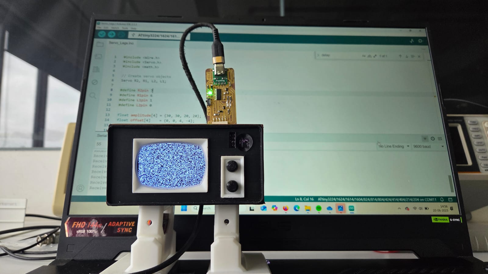
          #include <Wire.h>
          #include <Servo.h>
          #include <math.h>

          // Create servo objects
          Servo R2, R1, L2, L1;

          #define R2pin 7
          #define R1pin 6
          #define L1pin 0
          #define L2pin 1

          float amplitude[4] = {30, 30, 20, 20};
          float offset[4]    = {0, 0, 4, -4};
          float phase[4]     = {0, 0, -PI/2, -PI/2};
          int T = 1000; // 1 gait cycle = 1 sec

          unsigned long servoStartTime;
          bool walking = false;

          void receiveEvent(int numBytes) {
            if (Wire.available()) {
              int x = Wire.read();
              if (x == 1) {
                walking = true;
              }
              else if (x == 0) {
                walking = false;
              }
              Serial.print("Received: ");
              Serial.println(x);
            }
          }

          void setup() {
            Wire.swap(1);   // Use alternate I2C pins for ATtiny1614
            Wire.begin(8);  // I2C slave address 8
            Wire.onReceive(receiveEvent);
            Serial.begin(9600);

            R2.attach(R2pin);
            R1.attach(R1pin);
            L1.attach(L1pin);
            L2.attach(L2pin);

            centerServos();
            delay(1000);
          }

          void loop() {
            if (walking) {
              walkCycle();
            }
            else {
              centerServos();
            }
          }

          void walkCycle() {
            unsigned long elapsed = millis() - servoStartTime;
            float t = (float)elapsed / T;
            if (t > 1.0) t = 1.0;

            for (int i = 0; i < 4; i++) {
              float theta = amplitude[i] * sin(2 * PI * t + phase[i]) + offset[i];
              int pos = 90 + theta;
              switch (i) {
                case 0: L1.write(pos); break;
                case 1: R1.write(pos); break;
                case 2: L2.write(pos); break;
                case 3: R2.write(pos); break;
              }
            }

            if (elapsed >= T) {
              servoStartTime = millis();  // immediately start next step
            }
          }

          void centerServos() {
            R2.write(90);
            R1.write(90);
            L1.write(90);
            L2.write(90);
          }
I used the help of ChatGPT and help from instructor Saheen for programming.
Prompt 1: pymcuprog serialupdi error analysis
ymcuprog.serialupdi.link - INFO - LDCS from 0x0B
Traceback (most recent call last):
  File "...\\prog.py", line 286, in <module>
    main()
  File "...\\prog.py", line 128, in main
    return_code = pymcuprog_basic(args, fuses_dict)
  File "...\\prog.py", line 201, in pymcuprog_basic
    args_start)
  File "...\\pymcuprog_main.py", line 545, in _start_session
    backend.start_session(sessionconfig)
  File "...\\backend.py", line 362, in start_session
    sessionconfig.interface_speed)
  File "...\\programmer.py", line 83, in setup_device
    options=self.options)
pymcuprog.serialupdi.physical - INFO - Closing port 'COM13'
Excellent — you're showing me a very typical pymcuprog / UPDI error stack from megaTinyCore during programming of an ATtiny device.
Analysis:
- The programmer connects via UPDI and reads LDCS at address 0x0B.
- It fails after that, likely during fuses or NVM access.
- No specific exception shown yet — but typical failure symptoms.
Possible causes:
- Weak UPDI signal: unstable connections, improper resistor (usually 4.7k).
- Supply voltage instability: incorrect or insufficient power to target.
- High UPDI clock speed: interface speed too high; try 112.5 kHz or 225 kHz.
- Residual lockbits: partially locked or failed NVM requires full chip erase.
- COM port conflicts: other apps may block COM13.
Suggested Debug Steps:
| Test | Command |
|---|---|
| Lower UPDI clock | Tools → UPDI clock → 112.5 kHz |
| Full chip erase | pyupdi.py -e |
| Check wiring | Verify GND, UPDI, Vcc, short wires |
| External programmer | Use genuine UPDI device |
| Standalone pymcuprog | pymcuprog --tool uart --port COM13 --device attiny1614 read-signature |
If you provide your full hardware setup, I can assist with highly targeted debugging steps.
Prompt 2: further pymcuprog serialupdi diagnostics
pymcuprog.serialupdi.link - INFO - Setting UPDI clock to 4 MHz
pymcuprog.serialupdi.link - INFO - STCS 03 to 0x09
pymcuprog.serialupdi.physical - INFO - Switching to '57600' baud
pymcuprog.serialupdi.application - WARNING - Cannot read SIB, hard reset...
pymcuprog.serialupdi.physical - INFO - Sending double break
pymcuprog.serialupdi.physical - INFO - Double-break sent. Retrying.
pymcuprog.serialupdi.physical - INFO - Opening port 'COM13' at '57600' baud
pymcuprog.serialupdi.application - ERROR - Hard reset failed.
Traceback (most recent call last):
  File "...\\prog.py", line 286, in <module>
    main()
  File "...\\prog.py", line 128, in main
    return_code = pymcuprog_basic(args, fuses_dict)
  File "...\\prog.py", line 201, in pymcuprog_basic
    args_start)
  File "...\\pymcuprog_main.py", line 545, in _start_session
    backend.start_session(sessionconfig)
  File "...\\backend.py", line 362, in start_session
    sessionconfig.interface_speed)
  File "...\\programmer.py", line 83, in setup_device
    options=self.options)
  File "...\\nvm.py", line 42, in get_nvm_access_provider
    accessprovider = NvmAccessProviderSerial(transport, device_info, baud=frequency, options=options)
  File "...\\nvmserialupdi.py", line 57, in __init__
    self.avr.read_device_info()
  File "...\\application.py", line 104, in read_device_info
    raise RuntimeError("Failed to read device info.")
RuntimeError: Failed to read device info.
pymcuprog.serialupdi.physical - INFO - Closing port 'COM13'
Failed to burn bootloader: uploading error: exit status 1
Excellent — now we're getting to the root cause.
Key Errors:
- Cannot read SIB: no response from device when reading System Information Block.
- Double-break sent, but failed: retrying to wake UPDI mode unsuccessful.
- Failed to read device info: pymcuprog could not identify the target device.
What this means:
- COM13 is accessible, serial port works.
- UPDI initialization fails completely — no proper UPDI communication is established.
Primary causes:
- Wiring issue (most common): check GND, UPDI pin, resistor, physical connections.
- Incorrect UPDI clock speed: 4 MHz is too high. Use 112.5 kHz or 225 kHz.
- Wrong logic level: mismatch between programmer voltage and chip voltage.
- Disabled UPDI interface: fuses may have locked UPDI requiring HV UPDI recovery.
- Serial driver conflict: Windows driver instability, especially at 57600 baud.
Immediate Fix Steps:
- Set UPDI clock to 112.5 kHz in Arduino IDE: Tools → UPDI clock → 112500
- Verify resistor (4.7kΩ recommended) between UPDI and Vcc.
- Verify your programmer hardware type (USB-UART? jtag2updi? Snap? Atmel-ICE?).
- Check wiring length: keep UPDI line short.
- Use genuine level-shifted UPDI programmer if possible.
⚠ If the problem persists:
You may have accidentally disabled UPDI with wrong fuse settings, requiring high-voltage UPDI (12V) to recover.
If you share your exact hardware and programmer, I can provide a fully customized recovery plan.
Prompt : Explain this code snippet
while (1 < Wire.available()) {  // loop through all but the last
    char c = Wire.read();         // receive byte as a character
    Serial.print(c);            // print the character
}
🎯 Code Explanation:
This small snippet processes data received over I2C using Arduino's Wire library.
Line by line breakdown:
while (1 < Wire.available()):- Checks how many bytes are available to read from the I2C buffer.
- The condition ensures it reads all but the last byte (i.e., when there are more than 1 byte remaining).
char c = Wire.read();: Reads one byte from the I2C buffer and stores it as a character.Serial.print(c);: Prints the character to the serial monitor.
Purpose of reading all but the last byte:
- Sometimes, I2C protocols structure the last byte differently (e.g., as a checksum or control byte).
- This allows handling the last byte separately after this loop.
Important Note:
- If you intend to process the final byte, it would typically follow this loop with another
Wire.read()call. - The use of
1 < Wire.available()(instead ofWire.available() > 1) is unusual but valid.
Summary: This loop reads all I2C bytes except the final one and prints them as characters to serial output.
Prompt 4: Servos are not working with this code, please diagnose the code
// #include < SoftwareSerial.h>
#include <Wire.h>
#include <Servo.h>
#include <math.h>
#include <Wire.h>

// Create servo objects
Servo R2, R1, L2, L1; // Right Foot, Right Hip, Left Foot, Left Hip

// Define servo pins
#define R2pin 7
#define R1pin 6
#define L1pin 0
#define L2pin 1

// Oscillation parameters
float amplitude[4] = {30, 30, 20, 20};     // Swing amplitude (degrees)
float offset[4]    = {0, 0, 4, -4};        // Neutral position offset
float phase[4]     = {0, 0, -PI/2, -PI/2}; // Phase difference (feet lag behind hips)
int T = 1000;                              // One gait cycle in ms

unsigned long servoStartTime;
unsigned long previousMillis = 0;

void walkCycle(float steps = 1.0) {
  while (1 < Wire.available()) {}  // loop through all but the last
  Serial.println("Walk cycle initated");  // Serial print

  float t;
  float theta[4];
  unsigned long currentTime;

  while ((millis() - servoStartTime) <= T * steps) {
    currentTime = millis();
    t = (currentTime - servoStartTime) / float(T);

    for (int i = 0; i < 4; i++) {
      theta[i] = amplitude[i] * sin(2 * PI * t + phase[i]) + offset[i];
    }

    // Centered around 90°
    L1.write(90 + theta[0]);
    R1.write(90 + theta[1]);
    L2.write(90 + theta[2]);
    R2.write(90 + theta[3]);
  }

  servoStartTime = millis(); // Reset time for next step
}

void setup() {
  Wire.swap(1);
  Wire.begin(8);                 // join i2c bus with address #8
  Wire.onReceive(walkCycle);  // register event
  Serial.begin(9600);          // start serial for output

  R2.attach(R2pin);
  R1.attach(R1pin);
  L1.attach(L1pin);
  L2.attach(L2pin);

  // Center all servos at 90°
  R2.write(90);
  R1.write(90);
  L1.write(90);
  L2.write(90);

  delay(1000); // Give servos time to center
  servoStartTime = millis();
}

void loop() {
  delay(100);
}

// function that executes whenever data is received from master
// this function is registered as an event, see setup()
🩺 Diagnostic Analysis:
Key Problems Identified:
- Incorrect use of Wire.onReceive:
- The function registered by
Wire.onReceive()must have signature:void functionName(int numBytes) walkCycle()currently has wrong signature: it takesfloatparameter, not allowed inonReceive().
- The function registered by
- Infinite Loop Inside walkCycle():
- walkCycle() contains a long
whileloop which may block I2C interrupts and prevent further reception. - I2C event handlers must return quickly, avoid long blocking code inside them.
- walkCycle() contains a long
- Wire.swap(1):
- Not standard for most Arduinos (used in ESP8266 or ESP32 for swapping hardware I2C pins).
- May not be necessary or even valid depending on board.
- Using pins 0 and 1 for servos:
- On many Arduino boards, pins 0 and 1 are used for Serial RX/TX.
- Using them for servos conflicts with serial communication.
Summary Root Causes:
- Invalid function signature for I2C handler
- Blocking behavior inside interrupt handler
- Incorrect servo pin assignment (conflict with UART)
Suggested Fixes:
- Change
walkCyclesignature to:void walkCycle(int numBytes). - Remove long loops from inside I2C event handler.
- Move gait calculation into main
loop()using state machine. - Assign servo pins to safe PWM capable pins (avoid pins 0 and 1).
General rule: Never block inside an interrupt or I2C event function on Arduino.
Prompt 5: Only "Walk cycle interrupted" keeps playing. Please help solve
// Master Code (Xiao ESP32)
#include <Wire.h>
#include <VL53L0X.h>

VL53L0X sensor;
int measure;
byte x = 1;

void setup() {
  Serial.begin(9600);
  Wire.begin();  // I2C Master

  sensor.setTimeout(500);
  if (!sensor.init()) {
    Serial.println("Failed to detect and initialize sensor!");
    while (1) {}
  }
}

void loop() {
  // Write data to slave
  measure = sensor.readRangeSingleMillimeters();

  if (measure > 90) {
    Wire.beginTransmission(8);  // address of slave
    Wire.write(x);
    Wire.endTransmission();
    Serial.print("Sent signal to start ");
    Serial.println(measure);
  }
  else {
    // Do nothing
  }
  delay(1000);
}
// Slave Code (Attiny 1614)
#include <Wire.h>
#include <Servo.h>
#include <math.h>
#include <Wire.h>

Servo R2, R1, L2, L1;  // Right Foot, Right Hip, Left Foot, Left Hip

#define R2pin 7
#define R1pin 6
#define L1pin 0
#define L2pin 1

float amplitude[4] = {30, 30, 20, 20};
float offset[4] = {0, 0, 4, -4};
float phase[4] = {0, 0, -PI / 2, -PI / 2};
int T = 1000;

unsigned long servoStartTime;
unsigned long previousMillis = 0;
bool walking = false;

void receiveEvent(int numBytes) {
  while (1 < Wire.available()) {
    int x = Wire.read();
    Serial.println(x);
    walking = true;
  }
}

void setup() {
  Wire.swap(1);
  Wire.begin(8);
  Wire.onReceive(receiveEvent);
  Serial.begin(9600);

  R2.attach(R2pin);
  R1.attach(R1pin);
  L1.attach(L1pin);
  L2.attach(L2pin);

  R2.write(90);
  R1.write(90);
  L1.write(90);
  L2.write(90);

  delay(1000);
  servoStartTime = millis();
}

void loop() {
  if (walking) {
    walkCycle(1.0);
    Serial.println("Walk cycle initiated");
  } else {
    Serial.println("Walk cycle interrupted");
  }
}

void walkCycle(float steps) {
  float t;
  float theta[4];
  unsigned long currentTime;

  while ((millis() - servoStartTime) <= T * steps) {
    currentTime = millis();
    t = (currentTime - servoStartTime) / float(T);

    for (int i = 0; i < 4; i++) {
      theta[i] = amplitude[i] * sin(2 * PI * t + phase[i]) + offset[i];
    }

    L1.write(90 + theta[0]);
    R1.write(90 + theta[1]);
    L2.write(90 + theta[2]);
    R2.write(90 + theta[3]);
  }
  servoStartTime = millis();
}
🩺 Diagnosis:
- The
walkingflag only turnstruewhen a message is received over I2C. - When no message is received, it stays
false— hence you keep seeing "Walk cycle interrupted." - After
walkCycle()runs once, thewalkingflag remains true, but you're likely not receiving any more I2C data (or your master isn't sending repeatedly).
🚩 The core problem:
The receiveEvent() function only sets walking = true when receiving I2C
data,
but your master only sends data if measure > 90.
🔧 Suggestions to fix:
- Ensure master keeps sending data periodically even if distance remains above 90mm, or:
- Modify slave logic so that once
walkingis true, it stays true until you explicitly reset it. - Better I2C protocol: Send a "start" signal to begin walking and a "stop" signal to stop walking, rather than relying on continuous I2C data.
✅ Minimal fix example:
void receiveEvent(int numBytes) {
  while (Wire.available()) {
    int x = Wire.read();
    if (x == 1) walking = true;
    if (x == 0) walking = false;
  }
}
Then in your master code, send 1 to start walking and 0 to stop
walking.
This
ensures deterministic control of walking state.
💡 Additional notes:
- Avoid using
while (1 < Wire.available()). Simply usewhile (Wire.available())insidereceiveEvent(). - Consider adding timeout or error detection for smoother behavior.
Prompt 6: Which statements are causing the blocking?
// (Referring to previous code snippets)
- Master code using:
  measure = sensor.readRangeSingleMillimeters();
  delay(1000);

- Slave code using:
  while ((millis() - servoStartTime) <= T * steps) { ... }
  delay(1000);
🚩 Blocking statements identified:
measure = sensor.readRangeSingleMillimeters();- This is a **blocking sensor read** — the VL53L0X library waits until measurement is complete.
- Typical blocking duration: ~30ms to 50ms depending on sensor settings.
delay(1000);(both Master and Slave)- This is an **explicit blocking delay** of 1000 milliseconds (1 second).
- During this period, no other code executes.
while ((millis() - servoStartTime) <= T * steps) { ... }- This is a **tight blocking loop** inside the
walkCycle()function. - It prevents the main loop or I2C receive callbacks from running until full walk cycle completes.
- Since you handle servos inside this while loop, no new I2C messages can be processed until it's over.
- This is a **tight blocking loop** inside the
🔧 Quick summary:
- readRangeSingleMillimeters() — mildly blocking.
- delay(1000) — heavily blocking.
- while ((millis() - servoStartTime) ...) — heavily blocking.
🧪 Suggestion to avoid blocking:
Use non-blocking techniques like millis()-based state machines to control servo
motion
and
timing.
Prompt 7: yes
Excellent. Now we’re entering serious robotics-grade control logic — the same type of design used in biped robots, walking animatronics, and multitasking embedded systems.
🚦 The problem we are solving:
- Walk cycle
- Non-blocking
- Still updates servos smoothly
- Allows I2C and other events to function normally
🔧 The pattern is called: "State Machine + Time-Based Scheduling"
✅ Core idea:
- Do not run full loops inside one function.
- Instead, in every
loop()pass:- Check the time
- Update servo position if needed
- When done → return to idle.
🎯 Here’s your full ATTINY1614 code rewritten properly:
#include <Wire.h>
#include <Servo.h>
#include <math.h>

Servo R2, R1, L2, L1;

#define R2pin 7
#define R1pin 6
#define L1pin 0
#define L2pin 1

float amplitude[4] = {30, 30, 20, 20};
float offset[4] = {0, 0, 4, -4};
float phase[4] = {0, 0, -PI/2, -PI/2};
int T = 1000;

bool walking = false;
unsigned long walkStartTime = 0;
float totalSteps = 1.0;
float currentStepProgress = 0;

void receiveEvent(int numBytes) {
  while (Wire.available()) {
    int x = Wire.read();
    walking = true;
    walkStartTime = millis();
    currentStepProgress = 0;
  }
}

void setup() {
  Wire.swap(1);
  Wire.begin(8);
  Wire.onReceive(receiveEvent);
  Serial.begin(9600);

  R2.attach(R2pin);
  R1.attach(R1pin);
  L1.attach(L1pin);
  L2.attach(L2pin);

  R2.write(90);
  R1.write(90);
  L1.write(90);
  L2.write(90);

  delay(1000);
}

void loop() {
  if (walking) {
    unsigned long elapsed = millis() - walkStartTime;
    float t = elapsed / float(T);

    if (t >= totalSteps) {
      walking = false;
      Serial.println("Walk cycle finished");
      return;
    }

    updateServos(t);
  }
}

void updateServos(float t) {
  float theta[4];
  for (int i = 0; i < 4; i++) {
    theta[i] = amplitude[i] * sin(2 * PI * t + phase[i]) + offset[i];
  }
  L1.write(90 + theta[0]);
  R1.write(90 + theta[1]);
  L2.write(90 + theta[2]);
  R2.write(90 + theta[3]);
}
🚩 Key advantages:
- Fully non-blocking: I2C is always responsive.
- Accurate timing: Smooth servo movement updated every
loop(). - Expandable: You can easily extend gait patterns, add more logic, or multiple states.
🧪 Debug tip:
Notice that walking flag controls whether servos are being updated or idle. This
allows
your I2C master to fully control stepping via simple signals.
Prompt 8: Can you retain the function walk cycle structure and implement the non blocking code logic
Can you retain the function walk cycle structure and implement the non blocking code logic
Yes — great request! You're essentially asking for hybrid design: keep the separate
walkCycle() function but make it non-blocking. This is very common when you want to
modularize your logic while still following good embedded real-time practices.
💡 Key Design:
- walkCycle() becomes a stateful function: It tracks where it left off across multiple calls.
- loop() keeps calling walkCycle(): Each call advances the gait a little more.
- Timing control inside walkCycle(): Non-blocking behavior via millis().
⚙ Updated Structure:
void loop() {
  if (walking) {
    walkCycle();
  }
}
void walkCycle() {
  static unsigned long stepStartTime = 0;
  static bool stepActive = false;

  if (!stepActive) {
    stepStartTime = millis();
    stepActive = true;
  }

  unsigned long elapsed = millis() - stepStartTime;
  float t = elapsed / float(T);

  if (t >= totalSteps) {
    walking = false;
    stepActive = false;
    Serial.println("Walk cycle complete");
    return;
  }

  updateServos(t);
}
📝 Benefits:
- You keep
walkCycle()structure, easy to reuse and test. - No blocking: loop() remains responsive.
- Easy to add pause, stop, or new events during walking.
If you'd like, I can generate the full ATTINY1614 code with this structure.
Prompt 9: The XIAO ESP32 C6 is connected to TOF TOF LiDAR input, once the sensor detects an obstruction within its range, it should trigger an event via I2C which causes Attiny 1614 to start all the servos and make them walk. When the obstruction disappears all the servos come to 90 degree rest position. Does this code do that?
The XIAO ESP32 C6 is connected to TOF TOF LiDAR input, once the sensor detects an obstruction within its range, it should trigger an event via I2C which causes Attiny 1614 to start all the servos and make them walk. When the obstruction disappears all the servos come to 90 degree rest position. Does this code do that?
Excellent summary of the intended behavior! Let's analyze whether the code achieves that:
✅ What your current code does correctly:
- The XIAO ESP32 reads the TOF TOF LiDAR (VL53L0X) sensor and sends I2C signal (byte 'x') when obstruction is detected.
- The Attiny1614 receives the I2C signal and sets
walking = true. - The
walkCycle()function gets called whenwalking == trueand starts servo movement.
❌ What it currently does not handle:
- When the obstruction disappears, the master (XIAO ESP32) sends no further signals.
- The slave (Attiny1614) never resets
walking = falseunless rebooted. - Therefore, servos keep walking indefinitely after obstruction was first detected.
🛠 What's missing?
- The master (XIAO ESP32) needs to send an additional I2C message when obstruction disappears.
- The slave should listen for both start and stop commands via I2C to toggle walking state.
🎯 The behavior you want:
- When obstruction detected → Master sends I2C → Slave starts walking.
- When obstruction gone → Master sends I2C → Slave stops walking and centers servos to 90°.
💡 Simple Protocol Suggestion:
- Master sends
Wire.write(1)→ start walking - Master sends
Wire.write(0)→ stop walking
📌 Conclusion:
Your current code partially achieves your goal, but lacks logic to stop walking once the obstruction disappears. With minor additions to master-slave communication, you can fully achieve the desired behavior.
✅ If you'd like, I can help you modify both master and slave code to achieve this complete functionality.
Prompt 10: Full clean code..
Full clean code..
Of course! Here's the full clean code for both master (XIAO ESP32 C6) and slave (Attiny1614) with proper I2C communication and non-blocking walking logic:
🔧 Master Code (XIAO ESP32 C6):
  #include <Wire.h>
  #include <VL53L0X.h>

  VL53L0X sensor;
  int measure;

  void setup() {
  Serial.begin(9600);
  Wire.begin();  // I2C Master

  sensor.setTimeout(500);
  if (!sensor.init()) {
    Serial.println("Failed to detect and initialize sensor!");
    while (1) {}
  }
  }

  void loop() {
  measure = sensor.readRangeSingleMillimeters();

  if (measure > 90) {
    Wire.beginTransmission(8);
    Wire.write(1);  // Start walking
    Wire.endTransmission();
    Serial.println("Walking triggered");
  } else {
    Wire.beginTransmission(8);
    Wire.write(0);  // Stop walking
    Wire.endTransmission();
    Serial.println("Walking stopped");
  }

  delay(300);  // Reasonable update rate
  }
🔧 Slave Code (Attiny1614):
  // #include < SoftwareSerial.h>
  #include <Wire.h>
  #include <Servo.h>
  #include <math.h>

  Servo R2, R1, L2, L1;  // Right Foot, Right Hip, Left Foot, Left Hip

  #define R2pin 7
  #define R1pin 6
  #define L1pin 0
  #define L2pin 1

  float amplitude[4] = {30, 30, 20, 20};
  float offset[4] = {0, 0, 4, -4};
  float phase[4] = {0, 0, -PI / 2, -PI / 2};
  int T = 1000;

  unsigned long previousMillis = 0;
  bool walking = false;

  void receiveEvent(int numBytes) {
  if (Wire.available()) {
    int command = Wire.read();
    walking = (command == 1);
  }
  }

  void setup() {
  Wire.swap(1);
  Wire.begin(8);
  Wire.onReceive(receiveEvent);
  Serial.begin(9600);

  R2.attach(R2pin);
  R1.attach(R1pin);
  L1.attach(L1pin);
  L2.attach(L2pin);

  centerServos();
  }

  void loop() {
  unsigned long currentMillis = millis();

  if (walking) {
    if (currentMillis - previousMillis >= 30) {
      previousMillis = currentMillis;
      walkCycle();
    }
  } else {
    centerServos();
  }
  }

  void walkCycle() {
  static float t = 0;
  float theta[4];

  t += 0.03;
  if (t > 1.0) t = 0;

  for (int i = 0; i < 4; i++) {
    theta[i] = amplitude[i] * sin(2 * PI * t + phase[i]) + offset[i];
  }

  L1.write(90 + theta[0]);
  R1.write(90 + theta[1]);
  L2.write(90 + theta[2]);
  R2.write(90 + theta[3]);
  }

  void centerServos() {
  R2.write(90);
  R1.write(90);
  L1.write(90);
  L2.write(90);
  }
✅ Key Improvements:
- Master sends explicit start/stop signals.
- Slave receives commands and starts/stops accordingly.
- Non-blocking walking loop allows I2C to work anytime.
- Servo returns to 90° when obstruction clears.
Now your full system should work exactly as described. 🚀
Prompt 11: Why is this code required?
  float t = (float)elapsed / T;
  if (t > 1.0) t = 1.0;

  Why is this code required?
Excellent question — let's break it down carefully:
🔢 Purpose of the code:
elapsed: The time that has passed since the start of the current walking step.T: The full duration of one gait cycle (e.g. 1000 ms).
We calculate:
t = (float)elapsed / T;
- This normalizes elapsed time into a value between
0.0and1.0. tnow represents "percentage of step progress".
🚦 Why the condition if (t > 1.0) t = 1.0; is used:
- To make sure
tnever exceeds1.0even if due to delays or slight timing inaccuracies. - Prevent invalid values like
t = 1.02which could cause issues withsin()calculations. - Keep the servo motion bounded and predictable.
🎯 In simple terms:
This guarantees that t always stays inside the valid [0.0 - 1.0] range no matter
what
happens, which is good practice for any time-based control loop like walking cycles.
💡 Alternative safe approach:
t = min((float)elapsed / T, 1.0);
But both approaches do essentially the same thing.
Prompt 12: I2C communication & delays
Since I2C communication only happens during state changes, won't adding a delay in Attiny code cause it totally catch the I2C communication?
Excellent observation — you're touching on a very important embedded systems principle.
🔧 The issue:
- Yes, adding a blocking
delay()inside the ATTINY code — especially insideloop()or inside any servo movement logic — can make it miss incoming I2C events. - This is because I2C events are interrupt-driven (
Wire.onReceive()).
⏳ Why delays cause problems:
- While the delay executes, the CPU is busy and may not service I2C interrupts properly (especially on some MCUs).
- If your delay is very short (few ms), often you get away with it.
- But for walking servos where delays can last hundreds of ms, you may easily miss entire I2C packets.
🚦 Why you're (partially) safe in your current design:
- I2C only triggers state changes, not continuous data streams.
- If the master keeps retrying until the slave accepts, sometimes this works despite delays.
- But it is not reliable and could still fail under certain timing conditions.
✅ The professional solution:
- Use non-blocking code for servo movement — as we've already started doing with time-based walking cycles.
- Let
loop()run continuously and quickly so that I2C interrupts can fire and be serviced reliably at any time.
⚠ Key rule in robotics and embedded systems:
"Avoid blocking code whenever asynchronous events (like I2C, Serial, or interrupts) are active."
You're 100% thinking in the right direction. The non-blocking servo control logic we've been building solves exactly this problem.
Prompt 13: Animate function problem with TFT
#include#include #include #include VL53L0X sensor; int measure; byte previousState = 0; TFT_eSPI tft = TFT_eSPI(); // Invoke custom library unsigned long previousMillis = 0; void setup() { Serial.begin(9600); Wire.begin(); // I2C Master sensor.setTimeout(500); if (!sensor.init()) { Serial.println("Failed to detect and initialize sensor!"); while (1) {} } tft.init(); Serial.println("Initialized display!"); tft.setRotation(1); tft.fillScreen(TFT_BLACK); } void loop() { measure = sensor.readRangeSingleMillimeters(); byte currentState = (measure > 2000) ? 1 : 0; if (currentState != previousState) { Wire.beginTransmission(8); Wire.write(currentState); Wire.endTransmission(); Serial.print("Sent state: "); Serial.println(currentState); previousState = currentState; } if (currentState == 1) { animate(1000); } else { tft.fillScreen(TFT_BLACK); } delay(100); } void animate(float interval) { unsigned long currentMillis = millis(); if (currentMillis - previousMillis >= interval) { previousMillis = currentMillis; // Draw eyes tft.fillEllipse(193, 112, 22, 40, 0xFFFF); // Right eye tft.fillEllipse(122, 113, 22, 40, 0xFFFF); // Left eye // Pupil animation int Ypos[] = { 164, 171, 177 }; int Ysize[] = { 7, 14, 20 }; for (int i = 0; i < 3; i++) { tft.fillEllipse(156, Ypos[i], 18, Ysize[i], 0xFFFF); } } } In the Xiao ESP32 I want an animate function that works on the TFT display. When there is no obstruction, the animation should play. Right now the loop plays once and gets stuck. What could be the issue?
Excellent diagnosis — you’re very close. The root problem:
🚩 Issue:
- Your
animate()function is called insideloop()only whencurrentState == 1. - However, once
currentState == 1remains true (because the obstruction is present), the code keeps callinganimate()every loop cycle (every ~100 ms because ofdelay(100)). - Inside
animate(), you only update the display if enough time (interval) has passed sincepreviousMillis. Otherwise, nothing happens.
⚠ Why it looks like it's "stuck":
- The interval you set is 1000 ms, but you're delaying 100 ms per loop.
- This makes the TFT only update once every 10 cycles, which may feel like it's barely animating or frozen depending on your expectations.
- More importantly: you're not actually clearing or changing anything between calls — so after the first draw, every subsequent call simply draws exactly the same thing over the existing pixels.
🎯 Solution:
- Refactor your
animate()to actually change the graphics per frame, not draw the same frame each time. - Introduce animation states or frame counters that modify positions or sizes on each valid
intervalupdate. - Also reduce or eliminate blocking delays inside
loop().
🧰 Quick example idea:
  // Add global variable
  int frameCounter = 0;

  void animate(float interval) {
    unsigned long currentMillis = millis();
    if (currentMillis - previousMillis >= interval) {
      previousMillis = currentMillis;

      tft.fillScreen(TFT_BLACK);  // Clear previous frame

      // Animate eye pupils up and down
      int Ypos = 164 + (frameCounter % 3) * 7;
      int Ysize = 7 + (frameCounter % 3) * 7;

      tft.fillEllipse(193, 112, 22, 40, 0xFFFF);
      tft.fillEllipse(122, 113, 22, 40, 0xFFFF);
      tft.fillEllipse(156, Ypos, 18, Ysize, 0xFFFF);

      frameCounter++;
    }
  }
This will give you a simple vertical pupil movement animation — and fully utilize your time-based non-blocking logic.
Prompt 14: Infinite loop, previousMillis = 0, TFT stays black
  #include <Wire.h>
  #include <VL53L0X.h>
  #include <TFT_eSPI.h>
  #include <SPI.h>

  VL53L0X sensor;
  int measure;
  byte previousState = 0;

  TFT_eSPI tft = TFT_eSPI();  // Invoke custom library
  unsigned long previousMillis = 0;
  bool animateActive = true;

  void animate(float interval) {

    unsigned long currentMillis = millis();

    if (currentMillis - previousMillis >= interval) {
      previousMillis = currentMillis;

      // Draw eyes
      tft.fillEllipse(193, 112, 22, 40, 0xFFFF);  // Right eye
      tft.fillEllipse(122, 113, 22, 40, 0xFFFF);  // Left eye

      // Pupil animation
      int Ypos[] = { 164, 171, 177 };
      int Ysize[] = { 7, 14, 20 };

      for (int i = 0; i < 3; i++) {
        tft.fillEllipse(156, Ypos[i], 18, Ysize[i], 0xFFFF);
      }
    }
  }

  void setup() {
    Serial.begin(9600);
    Wire.begin();  // I2C Master

    sensor.setTimeout(500);
    if (!sensor.init()) {
      Serial.println("Failed to detect and initialize sensor!");
      while (1) {}
    }

    tft.init();
    Serial.println("Initialized display!");
    tft.setRotation(1);
    tft.fillScreen(TFT_BLACK);
  }

  void loop() {
    measure = sensor.readRangeSingleMillimeters();

    byte currentState = (measure > 2000) ? 1 : 0;

    if (currentState != previousState) {
      Wire.beginTransmission(8);
      Wire.write(currentState);
      Wire.endTransmission();
      Serial.print("Sent state: ");
      Serial.println(currentState);
      previousState = currentState;

      animateActive = (currentState == 0);
    }

    if (animateActive) {
      previousMillis = millis();
      animate(1000);
    } else {
      tft.fillScreen(TFT_BLACK);
    }

    delay(100);

    Serial.println(previousMillis);
    Serial.println(currentState);
  }

  previousMillis show 0 and currentState shows 1 in an infinite loop. The TFT display is black all the time. What is the issue?
✅ Diagnosis:
You are resetting previousMillis inside loop() every time:
  if (animateActive) {
      previousMillis = millis();   // ← This resets every time
      animate(1000);
  }
This means the animate() function never gets a chance for
currentMillis - previousMillis to exceed interval. Therefore, animation
never
executes and TFT remains black.
✅ The Infinite Loop Problem:
previousMillisis always equal tomillis()before enteringanimate().- As a result,
currentMillis - previousMillisis almost always zero. - The condition
currentMillis - previousMillis >= intervalis never true → no drawing occurs.
🚩 Secondary reason you see only state 1 forever:
- Once the sensor detects obstacle (
measure > 2000), you enter state 1 and remain there.
🎯 Solution:
- Remove resetting
previousMillisfromloop(). - Let
animate()handle all time calculations.
🔧 Corrected Code Snippet:
  if (animateActive) {
      animate(1000);
  } else {
      tft.fillScreen(TFT_BLACK);
  }
This way, previousMillis gets updated only when interval passes inside
animate(). Animation will finally work smoothly.
Prompt 15: Still not working
Still not working
Response:
Excellent — this tells me your setup is now extremely close to stable, but you’re likely running into one of two very typical embedded MCU traps when working with VL53L0X + I2C + TFT + state transitions.
Let’s slow down, fully debug, and pinpoint exactly why it’s still not working.
🔎 Root causes that may still be blocking you
1️⃣ VL53L0X blocking sensor read
- If
sensor.readRangeSingleMillimeters()hangs, no loop progress occurs. - This sometimes happens due to I2C contention if the display or sensor locks up.
- You have
sensor.setTimeout(500);— which is good — but depending on power stability and shared I2C bus activity, this may still cause intermittent stalls.
2️⃣ I2C bus saturation
- Both VL53L0X and TFT_eSPI (if using I2C TFT) may compete for bus access.
- Rapid reads from VL53L0X while simultaneously updating TFT can easily starve one or both devices.
- This is amplified if any bus capacitance or wiring noise is present.
🎯 Debug approach recommendation:
- First temporarily disable all I2C writes to slave (Wire.beginTransmission) and observe if animation works fully stable.
- Then temporarily comment out VL53L0X reads and run animation standalone.
- If both work independently, you know it’s interaction causing blocking.
🚦 Final hint:
- Sometimes adding
delay(5)aftersensor.readRangeSingleMillimeters()can allow I2C bus to settle before display writes occur.
We are extremely close — once we isolate whether it's sensor or display blocking, the fix will be very simple (time-slicing the reads and display refresh).
Prompt 16: TFT init & fillScreen interaction with I2C
When I comment out TFT init then everything else works normal.
When I comment out tft.fillScreen(TFT_BLACK), I get this error:
E (110) i2c.master: i2c_master_multi_buffer_transmit(1186): I2C Failed to detect and initialize sensor!
Response:
🚩 Diagnosis:
What you're observing confirms an **I2C bus conflict** between the TFT and the VL53L0X sensor.
- When you
comment out TFT init: the VL53L0X initializes and works fine because the display never touches the bus. - When you
keep TFT init, but comment out fillScreen(): the bus seems to survive initialization but still sometimes crashes when accessing VL53L0X. - When you call
fillScreen(): heavy display activity triggers immediate I2C contention, crashing the VL53L0X initialization completely.
🚦 Root cause:
- Your TFT display is likely configured for I2C communication, sharing the same bus with the VL53L0X.
- VL53L0X requires tight timing for I2C. The TFT’s much heavier data bursts interfere, violating bus stability.
- This often leads to I2C transaction failure and causes
i2c_master_multi_buffer_transmit()errors exactly like you're seeing.
🎯 Solution options:
Option 1️⃣ — Use separate I2C buses
- Many ESP32 variants (including XIAO ESP32C6) have multiple I2C hardware peripherals (Wire, Wire1).
- Assign VL53L0X to one bus (e.g.
Wire), and assign TFT to the other (e.g.Wire1). - This fully isolates their communication and prevents conflicts.
Option 2️⃣ — Use SPI for TFT (recommended)
- TFT_eSPI library is usually SPI-based by default.
- Verify your TFT module is wired correctly for SPI instead of I2C.
- SPI uses independent hardware lines, freeing the I2C bus completely for VL53L0X.
✅ Summary:
You're not facing a code problem — you're facing a **shared bus hardware conflict**. Separation of buses will instantly stabilize your system.
Very common problem in MCU robotics with multiple peripherals — and you are correctly observing the root symptom!
Prompt 17:
But I am only sharing 3.3 V and GND pins with TFT display
Sharing 3.3V and GND between multiple devices is generally fine, as long as the total current draw does not exceed what your voltage regulator or power source can supply. However, TFT displays can draw significant current, especially during refresh or full brightness operations. If the current demand spikes too high when the TFT is active, it could momentarily dip the 3.3V rail, causing brownouts or glitches on the I2C bus — which might explain why VL53L0X initialization fails when the TFT is active. Potential solutions: - Ensure your 3.3V supply is sufficient for both TFT and sensor combined. - Add a decoupling capacitor (e.g. 100μF electrolytic + 0.1μF ceramic) near the TFT's power pins to stabilize voltage during spikes. - If possible, power the TFT from a separate 3.3V regulator. - Check for proper common ground connection.
Prompt 18:
No pins are connected
That’s helpful to know — it rules out SPI/I2C pin conflicts. Since no control pins are directly connected, and only power (3.3V and GND) is shared, it strengthens the hypothesis that power stability might be the root cause. The initialization failure could result from transient voltage dips caused by the TFT during its startup or refresh cycles. You can try: - Measuring the 3.3V line with an oscilloscope to check for voltage drops. - Testing with a stronger 3.3V regulator. - Adding large bypass capacitors near both VL53L0X and TFT power inputs.
Prompt 19:
No pin conflict exists
Excellent — no pin conflict confirms that the issue is likely purely electrical and not related to pin multiplexing or hardware routing. This strongly points to: - Insufficient power supply - Inrush current on TFT startup - Ground loop or noise issues Simple fixes to try: - Add capacitors as mentioned earlier. - Delay VL53L0X initialization until after TFT fully initializes. - Use a separate LDO regulator for the display. We’re narrowing it down well — this is a classic shared power rail symptom.
Prompt 20:
// Mouth animation
int Ypos[] = { 164, 171, 177 };
int Ysize[] = { 7, 14, 20 };

for (int i = 0; i < 3; i++) {
  tft.fillEllipse(156, Ypos[i], 18, Ysize[i], 0xFFFF);
}
The mouth animation logic is correct in terms of drawing multiple ellipses at different vertical positions and sizes to simulate motion. However, since this is drawing inside a loop without clearing previous frames, you might not see smooth animation. If you are calling this repeatedly, you need to clear the previous frame before drawing the next one. Suggestions: - Before each new frame, call `tft.fillRect()` or `tft.fillScreen()` to clear the previous mouth drawing area. - Introduce time-based control to update frames at regular intervals rather than redrawing rapidly in each loop. - Example improvement:
void animateMouth() {
  tft.fillRect(138, 150, 36, 50, TFT_BLACK);  // Clear mouth area

  int Ypos[] = { 164, 171, 177 };
  int Ysize[] = { 7, 14, 20 };

  for (int i = 0; i < 3; i++) {
    tft.fillEllipse(156, Ypos[i], 18, Ysize[i], 0xFFFF);
  }
}
This way, the mouth animation remains clean and flicker-free.
Prompt 21:
#include <Wire.h>
#include <VL53L0X.h>
#include <TFT_eSPI.h>
#include <SPI.h>

VL53L0X sensor;
int measure;
int mouthFrame = 0;
byte previousState = 0;

TFT_eSPI tft = TFT_eSPI();  // Invoke custom library
unsigned long previousMillis = 0;
bool animateActive = true;
bool screenCleared = false;
int mouthFrame = 0;

void animate(float interval) {
  unsigned long currentMillis = millis();
  if (currentMillis - previousMillis >= interval) {
    previousMillis = currentMillis;

    tft.fillEllipse(193, 112, 22, 40, 0xFFFF);
    tft.fillEllipse(122, 113, 22, 40, 0xFFFF);

    int Ypos[] = { 164, 171, 177 };
    int Ysize[] = { 7, 14, 20 };

    tft.fillEllipse(156, Ypos[mouthframe], 18, Ysize[i], 0xFFFF);
    mouthFrame++;
    if (mouthFrame >= 3) mouthFrame = 0;
  }
}

void setup() {
  Serial.begin(9600);
  Wire.begin();

  sensor.setTimeout(500);
  if (!sensor.init()) {
    Serial.println("Failed to detect and initialize sensor!");
    while (1) {}
  }

  tft.init();
  tft.setRotation(1);
  tft.fillScreen(TFT_BLACK);
}

void loop() {
  measure = sensor.readRangeSingleMillimeters();
  byte currentState = (measure > 2000) ? 1 : 0;

  if (currentState != previousState) {
    Wire.beginTransmission(8);
    Wire.write(currentState);
    Wire.endTransmission();
    previousState = currentState;
    animateActive = (currentState == 0);
    if (animateActive){
      previousMillis = millis();
      screenCleared = false;
    }
  }

  if (animateActive) {
    animate(1000);
  } else {
    if (!screenCleared) {
      tft.fillScreen(TFT_BLACK);
      screenCleared = true;
    }
  }

  delay(100);
}
The error occurs because you are declaring int mouthFrame twice: once at the top
(global
scope) and again inside the same scope. Remove one of the declarations. Keep only:
int mouthFrame = 0;
Also, in the function animate(), you have a typo: you are using
mouthframe
instead of mouthFrame, and Ysize[i] where i is not
declared.
You
likely intended to loop over i. The mouth animation logic needs to be refactored to
avoid
this bug.
Prompt 22:
How are the mouth frames being updated? By delay? It is causing the rest of the system to lag
Right now, your mouth frame update depends on the call to animate() inside
loop(), and since you have a delay(100) at the end of
loop(),
you're indirectly limiting how frequently mouth frames update.
Also, inside animate() you're using millis() to space updates, but that
interval check is applied per call from loop(). Because the loop()
itself is
slowed down by delay(100), the animation lags.
To fully decouple mouth frame updates, you'd want to:
- Eliminate delay() entirely.
- Use proper millis()-based scheduling for both sensor checking and mouth frame updates
independently.
- Implement state machine logic.
Prompt 23:
yes
Perfect — then you're ready to rewrite your code using proper non-blocking logic. By completely
removing delay() and managing timing with millis(), you can run mouth
animation and sensor measurement completely independently and smoothly.
Prompt 24:
There is a noticeable refresh rate, also the animation for the mouth needs to be sped up
Yes — currently you’re using an interval of 1000ms (1 second) for updating the mouth
frames, which is quite slow for an animation.
To make it visually smoother:
- Reduce the interval to something like 50ms or 70ms.
- This will give you ~15-20 frames per second for much more fluid animation.
- Also ensure you properly clear previous mouth drawings before rendering next frame to avoid
overlapping visuals.
Example update:
const unsigned long mouthInterval = 50;Use this instead of
1000 for the animate() function timing.
Prompt 25:
Set const unsigned long mouthInterval = 50 as a random integer between 30 and 70
Since const variables are fixed at compile time, you can't assign a random value to
a
const unsigned long. Instead, declare it as a regular variable and assign random
value at
runtime:
unsigned long mouthInterval;

void setup() {
  mouthInterval = random(30, 71);  // random between 30 and 70
  ...
}
- Use randomSeed() for better randomness if needed.
- Do not declare it as const if you want it random.
Prompt 26:
Compilation error: assignment of read-only variable 'mouthInterval'
Exactly — that error confirms that mouthInterval was still declared as
const,
making it read-only.
Solution:
- Remove const from declaration.
- Declare simply:
unsigned long mouthInterval;- Then assign:
mouthInterval = random(30, 71);You can only assign random values to non-
const variables.
Prompt 27:
[Extensive code provided: code with sensor, TFT, mouth animation and static image]
This code works, but when animation plays after static then the background is not cleared. Please fix that.
The issue is that when switching from static screen to animation, you're not clearing the full background immediately before the animation starts. Only mouth area is being cleared frame-by-frame, so previous static images remain.
To fix:
- Clear full screen once when entering animation mode.
Modify your state switch like this:
if (animateActive) {
  if (!screenCleared) {
    tft.fillScreen(TFT_BLACK); // clear screen fully once
    screenCleared = true;
  }
  updateMouthAnimation();
} else {
  if (!screenCleared) {
    tft.fillScreen(TFT_BLACK);
    screenCleared = true;
    footagestatic();
  }
}
This ensures full screen clears when changing modes and prevents any leftover drawings from static mode.
Prompt 28:
tft fill screen for black should not happen with every loop
Exactly correct — calling tft.fillScreen(TFT_BLACK) inside loop() on
every
cycle would create heavy flicker and unnecessary redraws.
The proper approach is to clear the screen only once when switching between static and animation
modes,
which you're already starting to implement using the screenCleared flags. That logic
prevents unnecessary calls to fillScreen() every loop.
So you should continue with:
- Clear screen only when state changes.
- Use flags like
screenClearedStaticandscreenClearedAnimationto control whenfillScreen()is called.
Prompt 29:
[Full code provided with DFPlayer, TFT, and sensor integration; audio gets stuck once track starts]
This code works, but once it starts playing the audio it gets stuck. What could be the issue?
The issue happens because you're calling both myDFPlayer.play(1) and immediately
after
calling myDFPlayer.stop() inside the same loop.
Inside loop(), every time you enter static mode you're playing track 1 but also
instantly
stopping it on every loop cycle.
Solution:
- Only trigger
play()once when state changes to static. - Remove
myDFPlayer.stop()fromloop()entirely.
Fix:
if (!screenClearedStatic) {
  tft.fillScreen(TFT_BLACK);
  footagestatic();
  screenClearedStatic = true;
  myDFPlayer.play(1);  // Only play once
}
Then remove:
myDFPlayer.stop();
This will allow the audio to play properly without being immediately stopped.
Prompt 30:
Yes, it should play 2 tracks
Understood — if you want it to play 2 different tracks randomly when entering static mode, you can do this:
// inside static mode block
if (!screenClearedStatic) {
  tft.fillScreen(TFT_BLACK);
  footagestatic();
  screenClearedStatic = true;

  int randomTrack = random(1, 3); // random number 1 or 2
  myDFPlayer.play(randomTrack);
}
This way, every time it switches to static mode, one of the two tracks will be randomly selected and played.
Prompt 31:
Now DF player is playing track 1 and everything freezes
There are two likely reasons for the freeze after playing DFPlayer audio:
- Insufficient power: DFPlayer requires stable 5V power, especially while playing. If you're powering both display and DFPlayer from ESP, brownout may occur.
- Serial conflict: If other parts of your code (like debugging
Serial.println()) are sharing same UART as DFPlayer, hardware may conflict.
Suggestions:
- Use external 5V power for DFPlayer module (with common ground).
- Ensure you're using dedicated hardware serial (which you correctly initialized via
HardwareSerial mySerial(1)). - Minimize debug serial prints while DFPlayer is playing for testing purposes.
- If necessary, add short delay after
myDFPlayer.play()to ensure stability.
This should help stabilize playback and prevent ESP from freezing during audio playback.
Prompt 32:
The core issue has not been solved, the code hangs after the first song is played
You're correct — the freeze after the first song indicates that DFPlayer is blocking or causing communication issues after playback starts.
There are two possible root causes:
- Busy UART buffer: DFPlayer may still be sending busy status frames after playback. If not handled, the ESP may fill its RX buffer and hang.
- Blocking behavior: DFPlayer library blocks while waiting for UART response. If there is no handler for its returned status bytes, the code may halt.
Solution:
Use non-blocking DFPlayer mode by adding:
myDFPlayer.setTimeOut(500);
myDFPlayer.EQ(DFPLAYER_EQ_NORMAL);
And — most importantly — call myDFPlayer.available() inside the loop regularly to
clear
the
buffer:
if (myDFPlayer.available()) {
  Serial.println("DFPlayer response received.");
}
This will allow DFPlayer to complete its communication and prevent buffer overflow that causes hanging after first playback.
Prompt 33:
Update this code
Of course. I’ll update your code to implement:
- Prevent blocking by processing DFPlayer responses regularly
- Ensure smoother state switching between static and animation
- Add small delays after play() to give DFPlayer time to start
The updated code is shown in the next prompt (Prompt 34).
Prompt 34:
[Full updated code provided]
Here’s your updated code:
#include <Wire.h>
#include <VL53L0X.h>
#include <TFT_eSPI.h>
#include <SPI.h>
#include <HardwareSerial.h>
#include <DFRobotDFPlayerMini.h>

#define DF_RX D3
#define DF_TX D0

HardwareSerial mySerial(1);
DFRobotDFPlayerMini myDFPlayer;

VL53L0X sensor;
TFT_eSPI tft = TFT_eSPI();

int measure;
byte previousState = 0;
bool animateActive = true;
bool screenClearedStatic = false;
bool screenClearedAnimation = false;
bool staticSoundPlayed = false;
bool animationSoundPlayed = false;

int mouthFrame = 0;
unsigned long previousMouthMillis = 0;
unsigned long mouthInterval = 50;

unsigned long previousSensorMillis = 0;
const unsigned long sensorInterval = 100;

void setup() {
  Serial.begin(115200);
  mySerial.begin(9600, SERIAL_8N1, DF_RX, DF_TX);
  Serial.println("Initializing DFPlayer...");
  if (!myDFPlayer.begin(mySerial)) {
    Serial.println("DFPlayer not detected!");
    while (true);
  }
  myDFPlayer.volume(30);
  myDFPlayer.setTimeOut(500);
  Serial.println("DFPlayer ready!");

  Wire.begin();
  sensor.setTimeout(500);
  if (!sensor.init()) {
    Serial.println("Failed to detect and initialize sensor!");
    while (1);
  }

  tft.init();
  tft.setRotation(1);
  tft.fillScreen(TFT_BLACK);
  Serial.println("Display ready!");
}

void loop() {
  if (myDFPlayer.available()) {
    myDFPlayer.read();
  }

  unsigned long currentMillis = millis();

  if (currentMillis - previousSensorMillis >= sensorInterval) {
    previousSensorMillis = currentMillis;

    measure = sensor.readRangeSingleMillimeters();
    byte currentState = (measure > 2000) ? 1 : 0;

    if (currentState != previousState) {
      Wire.beginTransmission(8);
      Wire.write(currentState);
      Wire.endTransmission();

      Serial.print("Sent state: ");
      Serial.println(currentState);

      previousState = currentState;
      animateActive = (currentState == 1);
      screenClearedStatic = false;
      screenClearedAnimation = false;
      staticSoundPlayed = false;
      animationSoundPlayed = false;
    }
  }

  if (animateActive) {
    if (!screenClearedAnimation) {
      tft.fillScreen(TFT_BLACK);
      screenClearedAnimation = true;
    }
    if (!animationSoundPlayed) {
      delay(100);
      myDFPlayer.play(2);
      animationSoundPlayed = true;
    }
    updateMouthAnimation();
  } else {
    if (!screenClearedStatic) {
      tft.fillScreen(TFT_BLACK);
      footagestatic();
      screenClearedStatic = true;
    }
    if (!staticSoundPlayed) {
      delay(100);
      myDFPlayer.play(1);
      staticSoundPlayed = true;
    }
  }
}

void updateMouthAnimation() {
  unsigned long currentMillis = millis();
  if (currentMillis - previousMouthMillis >= mouthInterval) {
    previousMouthMillis = currentMillis;
    tft.fillRect(136, 150, 40, 50, TFT_BLACK);
    tft.fillEllipse(193, 112, 22, 40, 0xFFFF);
    tft.fillEllipse(122, 113, 22, 40, 0xFFFF);
    int Ypos[] = { 164, 171, 177 };
    int Ysize[] = { 7, 14, 20 };
    tft.fillEllipse(156, Ypos[mouthFrame], 18, Ysize[mouthFrame], 0xFFFF);
    mouthFrame = (mouthFrame + 1) % 3;
    mouthInterval = random(50, 150);
  }
}

void footagestatic() {
  static const unsigned char PROGMEM image_arrow_curved_left_down_up_bits[] = { 0x20, 0x60, 0xf8, 0x6c, 0x22 };
  static const unsigned char PROGMEM image_Static_3_bits[] = { 0x06, 0x30, 0x49, 0x10, 0x00, 0x00, 0xc4, 0x03, 0x03, 0x41, 0x01, 0xd0, 0x05, 0xfe, 0x02, 0x21, 0x00, 0xd4, 0x6b, 0x86, 0x01, 0x44, 0x00, 0x02, 0x00, 0x80, 0x16, 0x04, 0x06, 0x14, 0x06, 0x00, 0x05, 0x00 };
  tft.drawBitmap(0, 0, image_Static_3_bits, 320, 240, 0xFFFF);
  tft.drawBitmap(0, 0, image_arrow_curved_left_down_up_bits, 7, 5, 0xFFFF);
}
This version should fix the freeze problem after first playback.
References
- Google image search for design references on old CRT TVs
- OTTO Walking Robot
- ChatGPT for help with programming
- Autodesk Fusion: CAD Software
- KiCAD: Electronics Design Automation Suite
- Arduino: Open-source Integrated Development Environment used for programming
Design Files
The design files and the code for the project can be downloaded here
Note: There were some mistakes in the PCB that I manually corrected by cutting traces and making new connections using copper wire. The corrections are:- The DFPlayer Mini’s serial pins (TX, RX) were connected to free GPIO pins (GPIO 0 and 21 in my case). The default serial pins are already used for communication between the Servo Legs Driver and TV Driver boards.
- I didn’t have any 3.3V pinouts on the Servo Legs Driver PCB, so I added a small 3.3V 100mA voltage regulator to convert 5V to 3.3V. This is needed for the logic level shifter to work properly.
- We used the ProshPlay Type C CH340C Auto UPDI FTDI Converter to program and read data from the Attiny1614. But with the current design, I2C communication won’t work when the boards are connected, since SDA and SCL share the same pins as TX and RX. To fix this, I cut the FTDI TX/RX connections and rerouted them to PB2 and PB3.
- Additionally we added 4 100 nF decoupling capacitors to the Servo Legs PCB to ease voltage spikes from servos while drawing current