Project Development
Timeline
- 08/05/2025- Made a lasercut cardboard mockup of my final project
- 09/05/2025-
- 10/05/2025- Updated a sketch showing an exploded view of of my final project and how each compenent will be integrated
- 11/05/2025- Started CAD designing that integrated various electronics
- 12/05/2025- Tested kerf bending, dovetail joint for laser cut wooden frame.
- 13/05/2025-
- Made a functional flow diagram
- Finalised audio system
- Confirmed pinouts for using ESP32-WROOM 32E
- Updated the BOM
- arranged the SD card reader in CAD
- 14/05/2025-
- Checked library compatibility and storage with alternate libraries
- Completed 70% of CAD design related to arranging of electronics
- 15/05/2025-
- Made changes on electronics placement in CAD based on instructor feedback
- Finalized arrangemnt of speaker and how to connect different boards together
- Changed assembly mechanism to two piece 3d printed housing attached with a lip and 5 mm magnets, decided on making a 2 piece mold using vaccum forming to make buttons for Lumi
- 16/05/2025-
- Completed 80% of CAD for arranging electronics, except servo placement and legs
- 45% of PCB designing for mounting the PCB
- 17/05/2025- TV Driver PCB schematic design completed
- 19/05/2025-
- Master PCB schematic design done
- Made lasercut mockup of mount PCB to confirm placement of screw holes of the TFT display
- 20/05/2025- TV Mount PCB layout design done, 3D model done, Vaccuum forming of potential molds for silicone buttons ended up in failure
- 21/05/2025-Redesign TV Mount PCB with connections for servos, Master PCB layout design is ongoing
- 22/05/2025-
- There are lots of potential problems with using rivets for connections in a double sided PCB, so the Master PCB has to be redesigned to be single sided
- Testing 3D printed standoffs
- Modified TV mount PCB schematic to use 2x5 pin SMD headers to provide two different 3.3V sources (one for the ESP32 and the other for all other electronics) and holes for 3D printed standoffs
- 23/05/2025-TV Mount PCB schematic redesign based on new design constraints
- 24/05/2025-
- Changes in CAD model due to change in choice of speaker and PCB
- Start fresh as Lumi V2; started CAD design of walking mechanism
- 28/05/2025- Completed assembly of the servo legs
- 29/05/2025- Made a basic walk cycle using the Xiao ESP32 C6
- 30/05/2025-
- Was able to integrate servos and TFT onto Xiao ESP32 C6, ended up breaking TFT display and hence had to replace it
- 80% done in programming a basic animation in TFT display, stuck due to a logical error using millis function
- Tested ToF sensor limit at 3.3V and 5V
- A seperate PCB will be required for servos controlled by a Attiny 1614 acting as a node in I2C communication
- PCB design of TV Driver and Servo Legs Driver PCB started
- 31/05/2025- PCB design of Servo Legs Driver done. PCB design of TV Driver completed by 50%
- 01/06/2025- PCB design of TV Driver done
- 02/06/2025- CAD design of TV head completed by 90%
- 03/06/2025- PCB production started
- 05/06/2025- A second PCB for TV Driver PCB milled and produced due to errors in flipping pnouts for the DF Player Mini and TFT display
- 07/06/2025- Due to serious changes in positioning of various elements of the PCB, TV Head had to be redesigned. The position of the TFT display and the Xiao USB C has been corrected
- 10/06/2025-Positioning of buttons, TOF TOF LiDAR sensor, battery charger, mounting screw holes between TV_case and TV_top, locator pin placement, SD card slot placement, hole for FTDI pins of Servo Driver PCB has been corrected, TV_case sent for 3D printing
- 11/06/2025-
- TV lid printed
- Vinyl Wrapper applied
- Mistakes in PCB corrected manually using enamel coated copper wire
- 12/06/2025-Programming started
- 13/06/2025-Minimum programming done.
What tasks have been completed, and what tasks remain?
By the time of final project presentations;
- Design and 3D printing of TV Head ✔
- Design and 3D printing of Legs ✔
- Detailing of TV Head using Vinyl Cutting ✔
- Design and production of TV Mount PCB ✔ (with minimum features)
- Design and production of Servo Legs PCB ✔
- Assembly of final project ✔
- Added a LIDAR TOF input ✔
- Programming a 'curious' facial animation ✔
- Programming a 'surprised' facial animation ✖
- Added TV static in the TFT display ✖
- Added TV footage in the TFT display ✖
- Added sound effects for TV static ✔
- Added sound effects for TV footage ✔
- Added sound effects for 'curious' facial expression ✔
- Added sound effects for 'surpised' facial expression ✔
- Added sound effects for TV footage ✔
- Programmed a minimum walk cycle ✔
- Make Lumi walk sideways ✖
- Integrate LIDAR TOF input with TFT display ✔
- Integrate LIDAR TOF input with Speakers ✔
- Integrate LIDAR TOF input with Servo Legs ✔
What's working? what's not?
- Due to the difficulty in integrating electronics into my system, I had to drop the idea of an SD card reader that stores TV footage, so currently I am unable to play long duration TV footage.
- By the time of the final project presentation Lumi does not play TV footage
- While each function (audio, video, and movement) plays individually in response to TOF TOF LiDAR input, there are some issues in syncing the timing of all three. By the time of final presentations, it would only work sometimes
- Lumi 'moves', but does not walk properly. The logic behind servo control must be modified.
- Only one facial animation plays. The facial animations should be improved to increase the interactiveness.
- Right now the TOF TOF LiDAR sensor reacts to all objects, including non-human objects. This means that reflections from surfaces, especially white surfaces cause Lumi to switch erraticly between 'TV' and 'alive' mode.
- The button switch gets obstructed on the base of the buttons and the TOF TOF LiDAR enclosure. To make space, the part of the TOF TOF LiDAR enclosure that obstrcuts the button had to be cut.The tip of the button also had to be cut to reduce its overall height
- The clearance between the buttons and the button frame should be increased
- The mounting of the hip servos must be made easier. One idea is to redesign the TV head so that one can add screws from below the base of the TV head
- Currently, the goal of easy dissassembly has not been achieved. to replace the hip servos, the whole mechanism has to be dissassembled. Also it is very hard to remove the TV Driver PCB because the clearance is too small
- The locator pins/lip/flange at the bottom of the TV_Top should be extended farther. The vinyl wrapper adds thickness which reduces the usefulness of the locator pins
- There is no visual indication of charging status, which needs improvement
- A debugging/power LED on the servo legs PCB would have been a good touch to improve debugging experience
- The speaker mounting method should be improved, at one point, the speaker would start sliding through and obstructing the servo legs.
By the time of final presentations
What questions need to be resolved?
These questions are yet to be resolved:
- There is some lag that occurs when integrating all three outputs; servos, TFT display and speakers together.
- Is it possible to program a few seconds of footage of a loopable animation in the TFT display without the use of an SD caed
- Is it possible to make Lumi 'crab walk' sideways?
What will happen when?
This question has been answered clearly in the section on Time Management
What have you learned?
Apart from the skills I have learnt as a part of other weeks, I have used the following processes in this project:
- Laser cutting - for initial prototyping in cardboard
- 3D printing - for making the outer body
- Vinyl cutting - to mimic a wood finish for the TV case
- PCB Designing - in KiCAD
- Milling - To make the PCB
- Soldering - To make the PCB
- Programming - In Arduino IDE & VS Code
Time Management
I made multiple attempts at scheduling my work, and I failed most of the time. The biggest reason being I underestimated the time I would required to complete a specific task
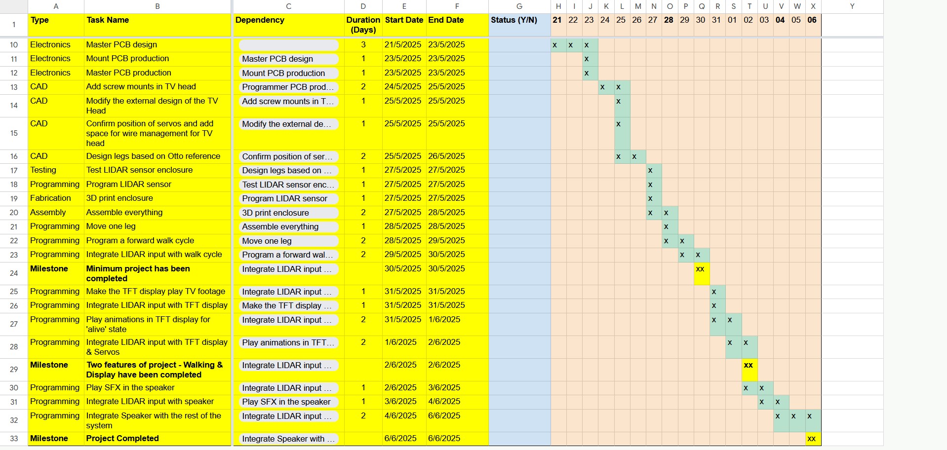
You can see my schedule here
Week 18: Assessing Project Progress
This is an assessment of my progress as of 29-05-2025:
-
What tasks have been completed, and what tasks remain?
- Master PCB design ✖
- Mount PCB design ✖
- Master PCB production ✖
- Mount PCB production ✖
- Master PCB production ✖
- CAD Add screw mounts in TV head ✖
- CAD Modify the external design of the TV Head ✖
- Confirm position of servos and add space for wire management for TV head ✖
- Design legs based on Otto reference ✔
- Test TOF TOF LiDAR sensor enclosure ✖
- Program TOF TOF LiDAR sensor ✖
- 3D print enclosure - 50%; Printed legs
- Assemble everything - 30%; Assembled legs
- Move one leg ✖
- Program a forward walk cycle ✖
Because I was struggling to design an integrated PCB and electronics enclosure that is easily dissassemblable for repairing, my instructor advised me to rethink my approach and start with the servo controlled legs. Also I greatly overestimated my speed and efficiency.
-
What's working? what's not?
At this point in time:
- The servos are not rotating 180 degrees completely
- The speakers can be operated using the MAX98357A amplifiers
- Kerf bending cannot be used to make the lasercut enclosure from birchwood without some kind of supporting material to strengthen the wood layer.
- I was not successful in making silicone molds from vacuum forming.
-
What questions need to be resolved?
- Can my robot walk successfully now that I know that the servos cannot rotate complete 180 degrees?
- Can I finish a minimum viable project in time; A TOF TOF LiDAR input, Display anf servo output, and a LiPo battery for charging.
- To simplify my design, I plan to change my microcontroller to a Xiao ESP32 to be able to easily program it without a programmer and to charge it with a LiPo battery.
-
What will happen when?
I am cutting out a lot of features. Right now all I have is a TFT display that can display some emotions, servo legs that help it walk, and a TOF TOF LiDAR input. The microcontroller will likely be a Xiao ESP32. I will be making a new schedule with the deadline of finishing within 6th June 2025
-
What have you learned?
Time management is crucial to successfully complete a project. This is one aspect I need more practice in.
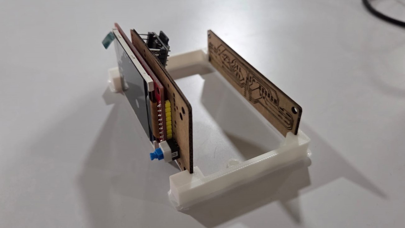
Making Mockups in Cardboard
08-05-2025: I lasercut a mockup design of my final project.
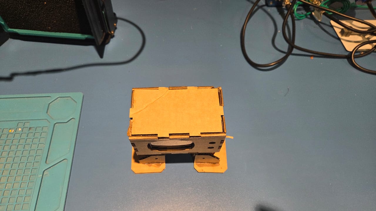
To test screw hole placement, I made laser cut mockups of my PCB design
I tested how the PCBs could fit without fasteners using a mechanism similar to a drawer slide.
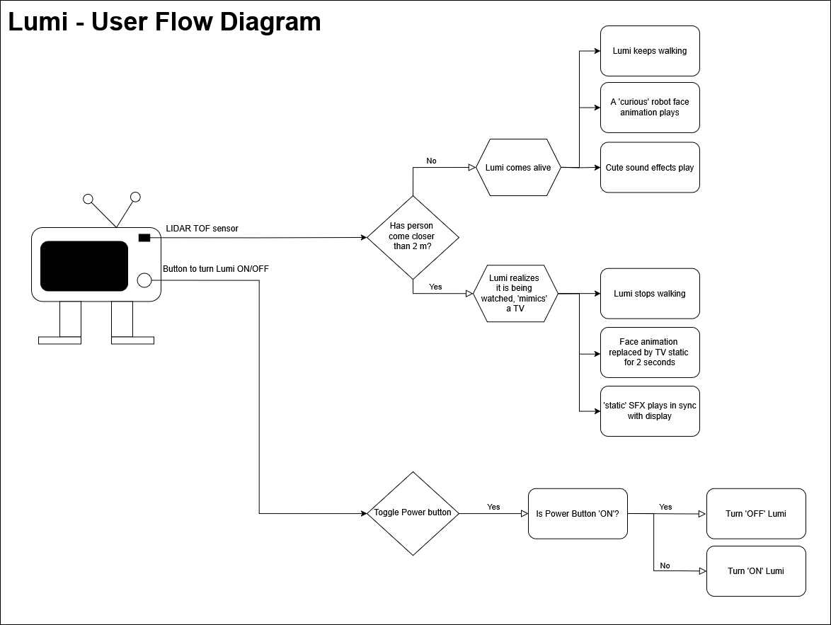
User Flow and Functional Flow
09/05/2025- During System Integration Week I made a system diagrams for user flow and function flow based on instructions from our instructor. This helped us in finalising all the electronics that would be used.
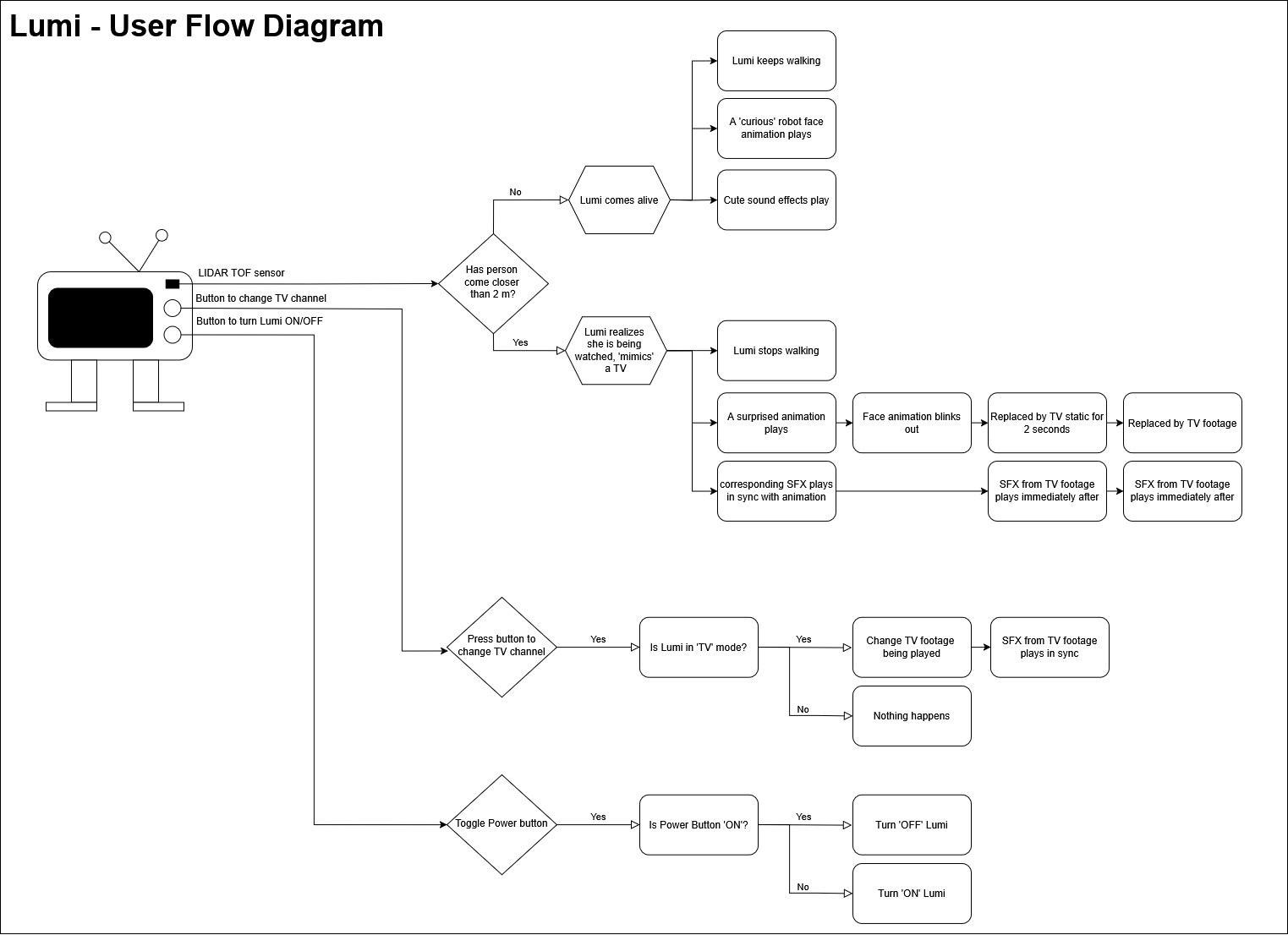
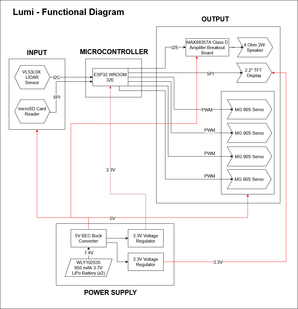
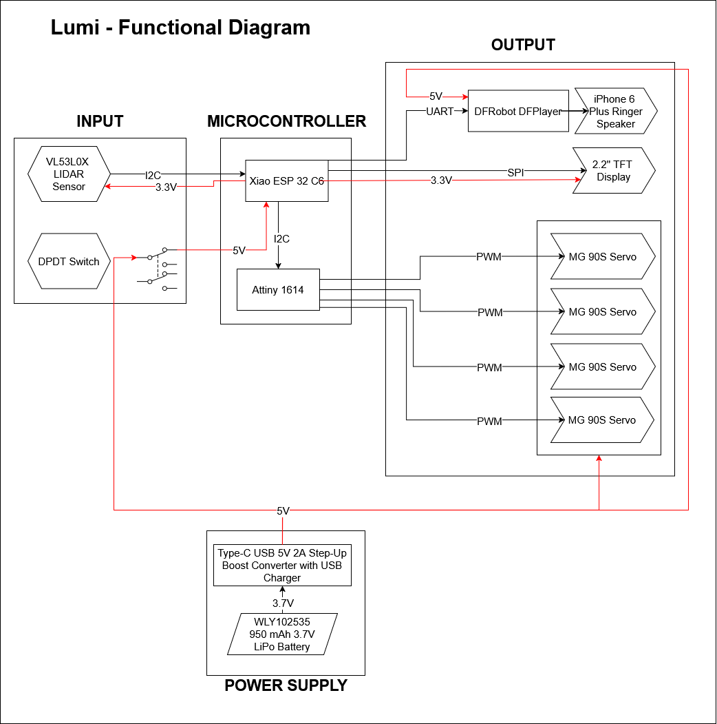
Later on, as I simplified my design due to time constraints, I updated the User and FunctionalFlow
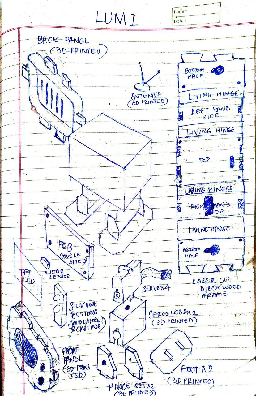
Sketching an Exploded View
10-05-2025: Updated a sketch showing an exploded view of of my final project and how each compenent will be integrated
13/05/2025-Today I confirmed the pinouts for ESP32-WROOM-32E. This guide to pinouts for ESP32 by Random Nerd Tutorials helped a lot, especially when I found it difficult to understand the terminology used in the official datasheet
SD Card Reader & TFT Display
| Pin | Description |
|---|---|
| 3.3V | Power Supply |
| GND | Ground |
| SCK | SPI Clock |
| MISO | SD Card Reader |
| MOSI | |
| CS (SD) | Chip Select for SD |
| CS (TFT) | Chip Select for TFT (any GPIO) |
| RST | Reset |
Note: LED ➝ 3.3V, SPI interface used
LiDAR Connections
| Pin | Description |
|---|---|
| 3.3V | Power Supply |
| GND | Ground |
| SCL | I2C Clock |
| SDA | I2C Data |
MAX98557 Audio Amplifier
| Pin | Description |
|---|---|
| LRC | Left-Right Clock |
| BCK | Bit Clock |
| DIN | Data In |
| GAIN | Connect to GND |
| GND | Ground |
| 5V | Power Supply |
Output ➝ Speaker
Servo Motor (x4)
| Pin | Description |
|---|---|
| Signal | Control Signal |
| GND | Ground |
| +5V | Power |
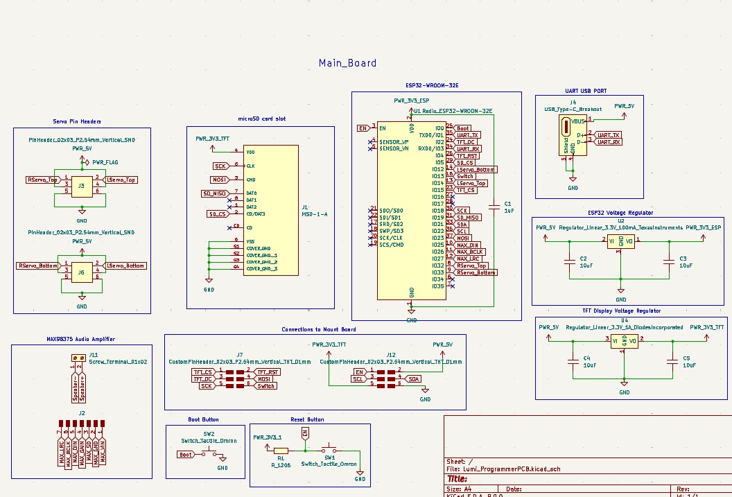
ESP32 WROOM-32E Pin Mapping
| ESP32 Pin | Function |
|---|---|
| IO0 | BOOT |
| GND | Ground |
| 3V3 | 3.3V Power |
| 26 | GND |
| 27 | LRC |
| 26 | BCLK |
| 25 | DIN |
| 32 | SDA |
| 33 | S2 |
| 34 | S3 |
| 12 | S4 |
| 23 | MOSI |
| 18 | SCK |
| 15 | CS (TFT) |
| 5 | CS (SD) |
| 4 | RST |
| 2 | DC |
| 19 | MISO |
| 21 | SCL |
Notes: “Don't use GPIOs 36, 39 – Analog only” and power requirements include 5V, 3.3V, and GND.
30-05-2025- An ongoing discussion was whether to opt for ESP32WROOM controlling everything or for a Xiao ESP32 C6 (to control the LIDAR TOF sensor, the TFT Display and the speaker) and Atiny 1614 combination (to control the Servo legs). Today, I decided to go with the Xiao-Attiny combination for more pinouts and an easier time in routing traces
These changes were integrated into the CAD design of the TV head as well
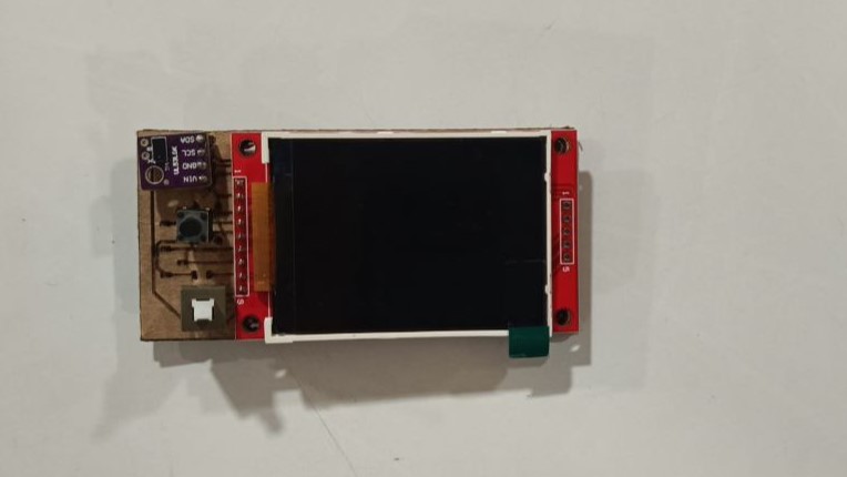
Testing TFT display
09-05-2025: Testing refresh rate of LCD screen to play animations and video footage
Testing Kerf Bending with Birch wood
12/05/2025- I tested kerf bending with 3mm birch wood. My test was a fail, since the radius needs to be at least 15 mm.
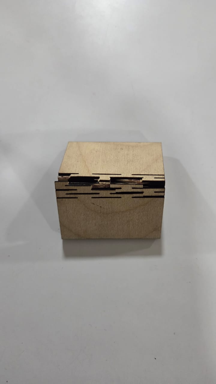
This led me to scrap the idea instead replacing it with vinyl cut wrapper to mimic a wood finish
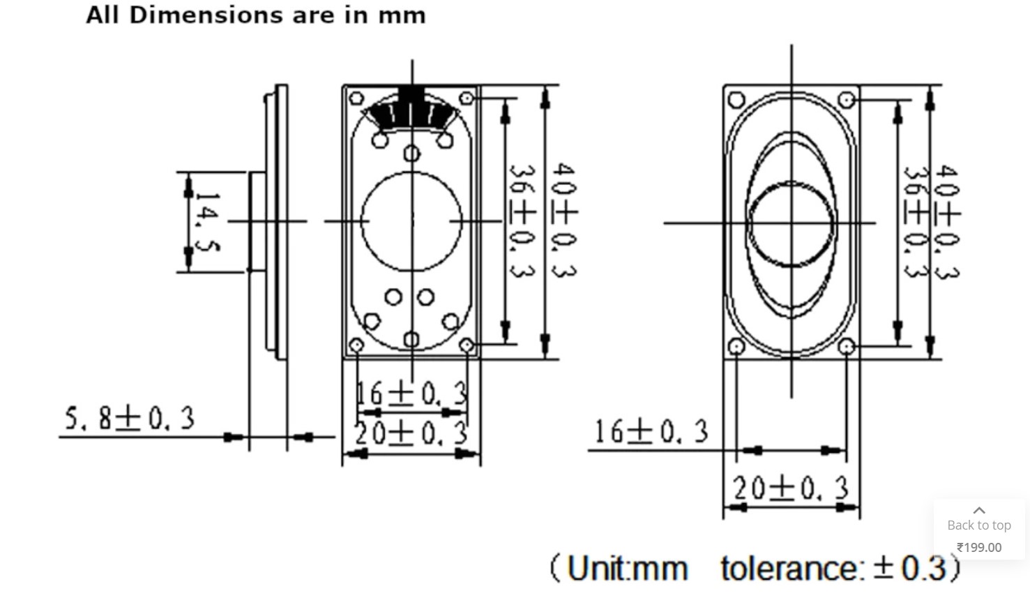
Speaker Testing
13/05/2025- Initially, I had chosen to purchase a 8 Ohm 2W speaker as shown below. I used measurements I obtained from online to make CAD models that I integrated into my early designs. Along with this speaker, I planned to use the MAX98357A Class D amplifier in combination with the ESP32-WROOM-32E
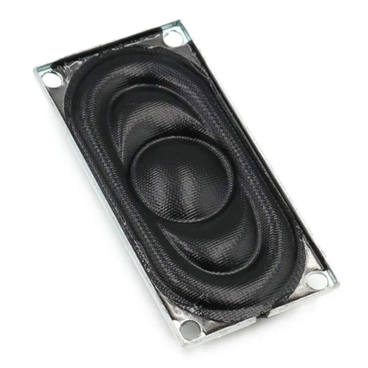
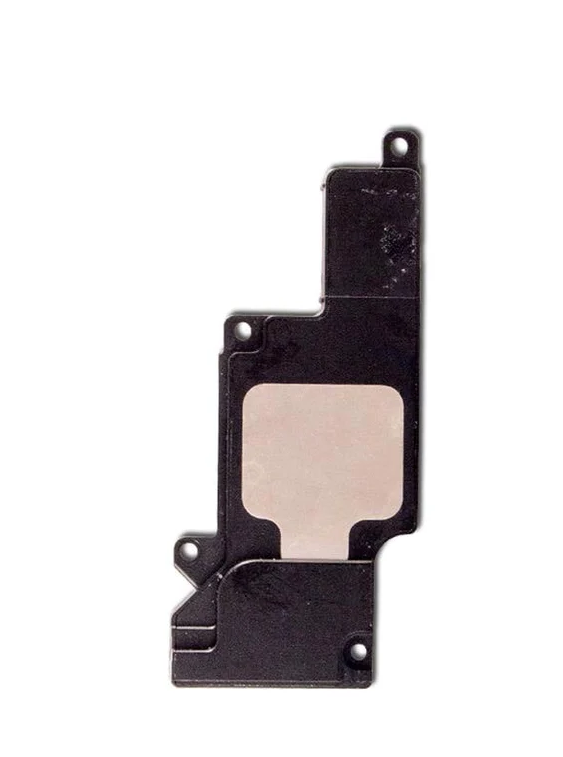
23/05/2025- But due to constraints in procurement, I had to switch to using the iPhone 6 Plus speaker
I was able to successfully test the functioning of the SD card player with the MAX98357A audio amplifer and the iPhone 6 Plus speaker with the help of Revi's code
Later on the MAX98357A audio amplifer was switched for DFPlayer Mini to reduce the complexity of PCB designing
CAD Design
11-16/05/2025: I started CAD designing, trying to integrate different electronics into a limited spaces
I made a finalised CAD model of my design that integrates all the electronics. To do this I first arranged all the electronics placement, then went to KiCAD if connections can be made in the desired arrangement, make minor changes, then reintegrate those changes in the CAD model.
As for aesthetics, I wanted it be small and cute. Initally I opted for a more rounded design to achieve this effect, but later on I changed it to more hard edges since old TVs had more hard edges rather than rounded corners
23/05/2025: Due to many changes in the design, I decided to start from scratch from the ground up after some advice from our instructor
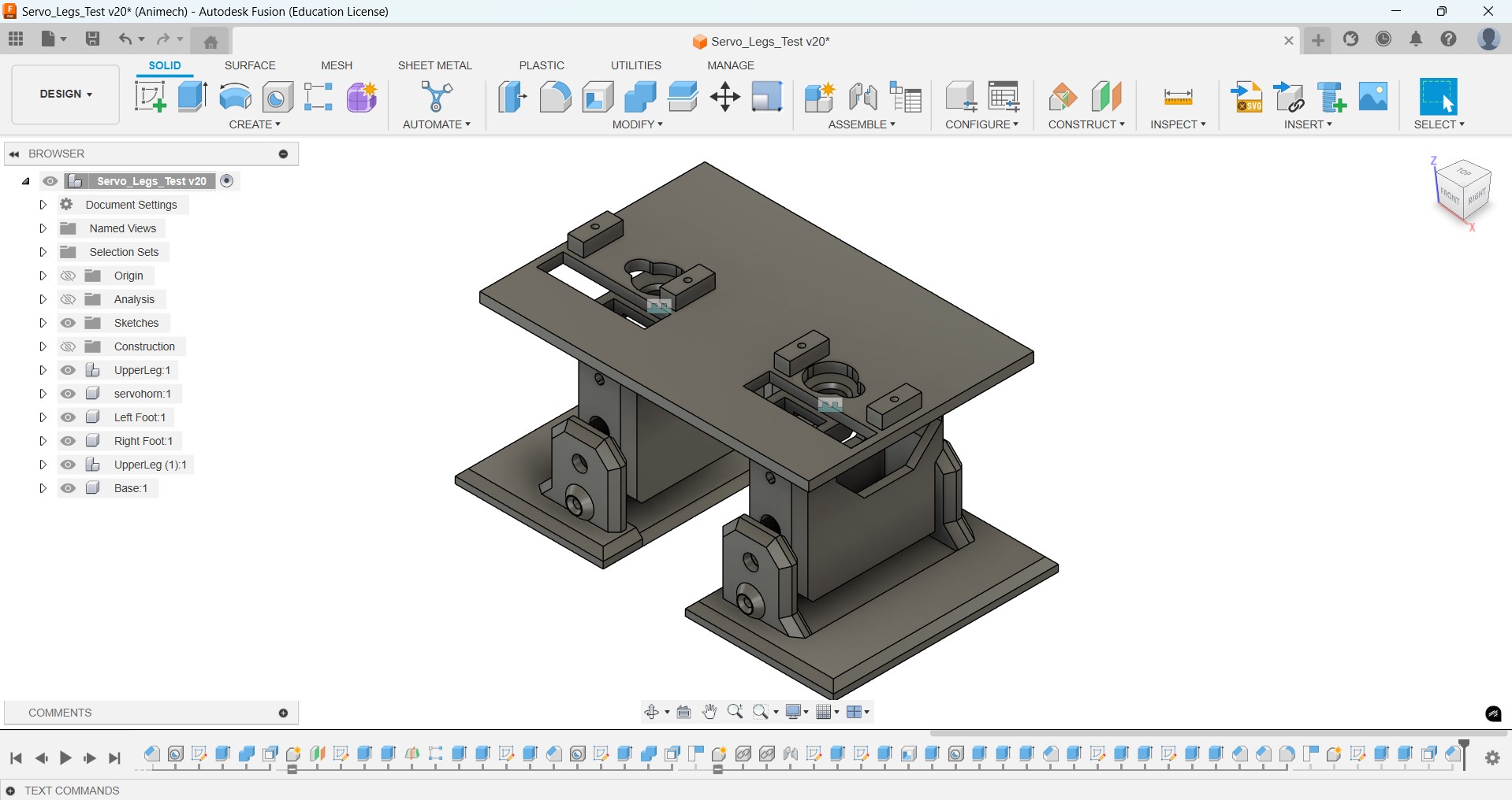
I started with designing the legs downloaded the STEP files of OTTO and used that as a reference to design my walking mechanism in Fusion, accommodating for changes in:
- the servo mount height
- the size of the servo horns
- changed position of the servos
Then I went on to testing the walking mechanism programmatically before I designed the TV head
Since I faced a lot of difficulties in routing traces for the PCB, I reduced or simplified the electronics inside. After some iterations this is how how the system integration of the Electronics would look like.
Then I made a CAD design showing how the inner electronics will be assembled. The screw holes will be used to mount each component
PCB Design
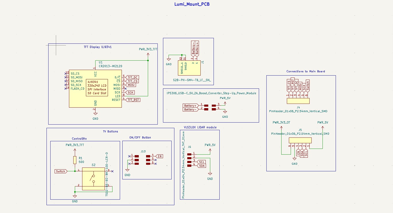
I designed two PCBs, the bigger 'mount' PCB that holds the front facing electronics; the LCD display and the switches, along with the battery on the back side. On this PCB, I stacked another doublesided PCB that holds all the internal electronics; including the microcontroller, the buck converter, the amplifer, along with the USB port and the micro SD card reader
I used this schematic that connected the
microSD card directly to their microcontroller. I adapted this for my Use
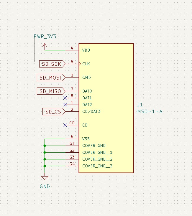
Question: Will the SD card work without pullup resistors between MOSI, MISO and SCK connections.
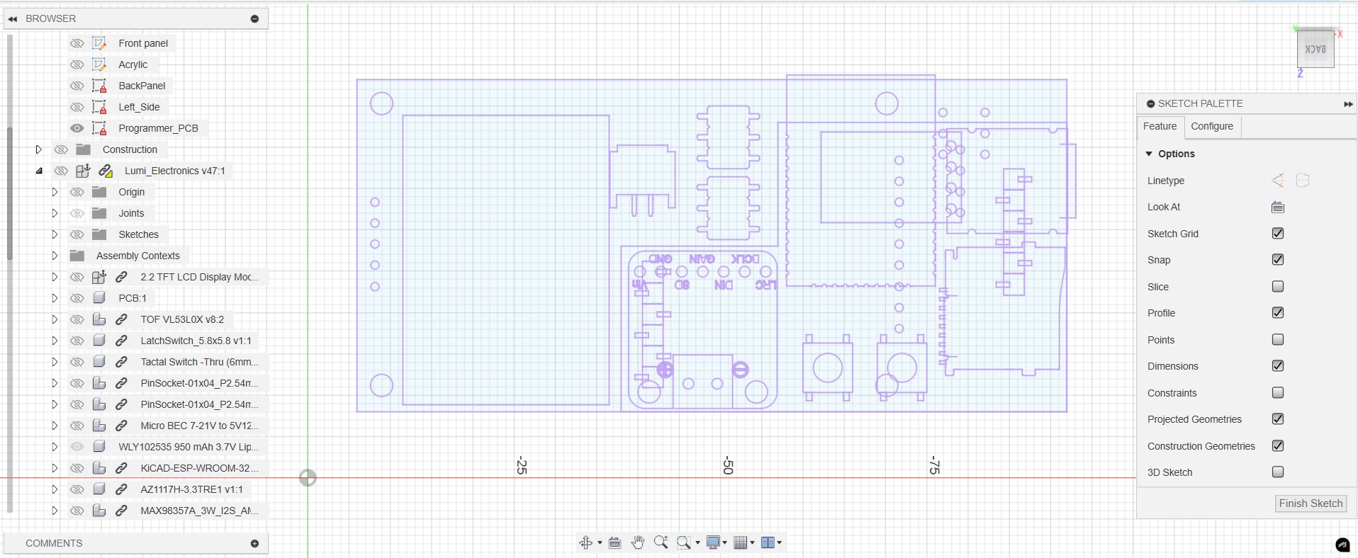
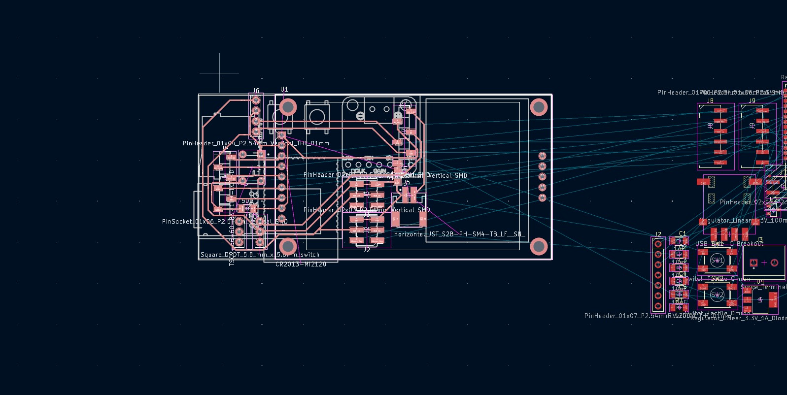
After I arranged all the components in Fusion, I projected a sketch of placements into KiCAD and used that as a reference to make my final PCB design, Due to pads and spaces for traces, the design will be slightly modified from original. Once my mount PCB design was done, I exported a CAD model back into Fusion, projected all reference geometries including from the battery, 2x3 pin headers, JST connectors and screw holes and edge cut of mount PCB into a new sketch that I exported as a DXF that I brought once again into KiCAD to repeat the steps.
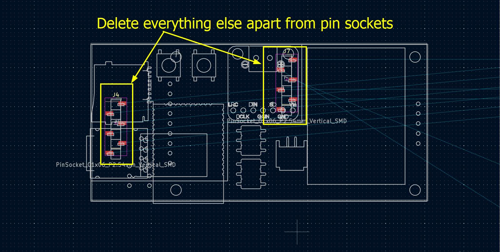
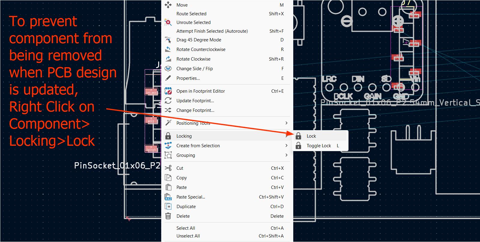
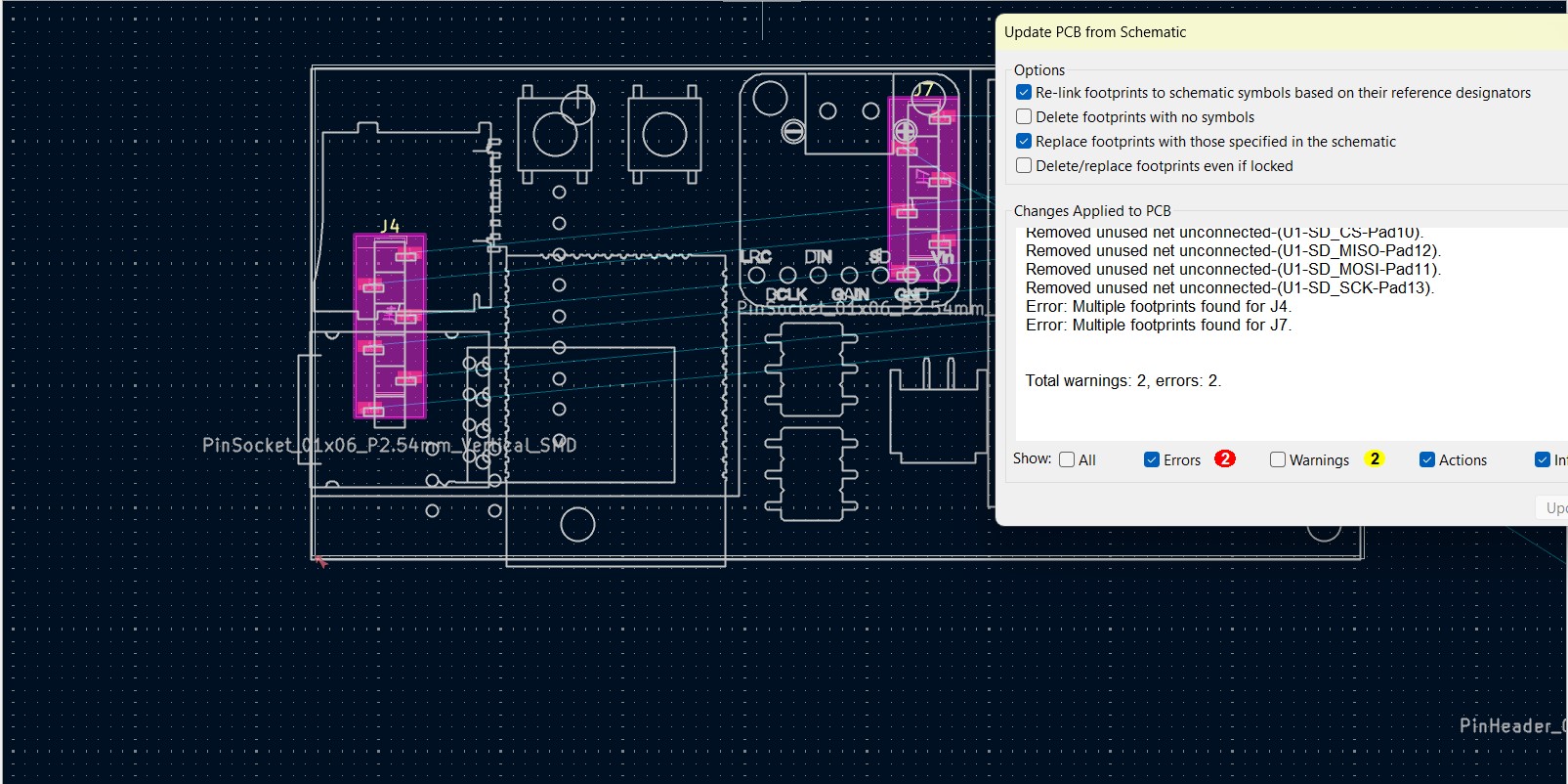
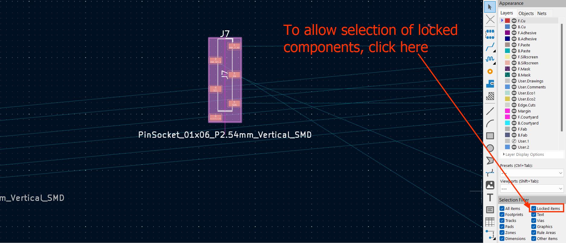
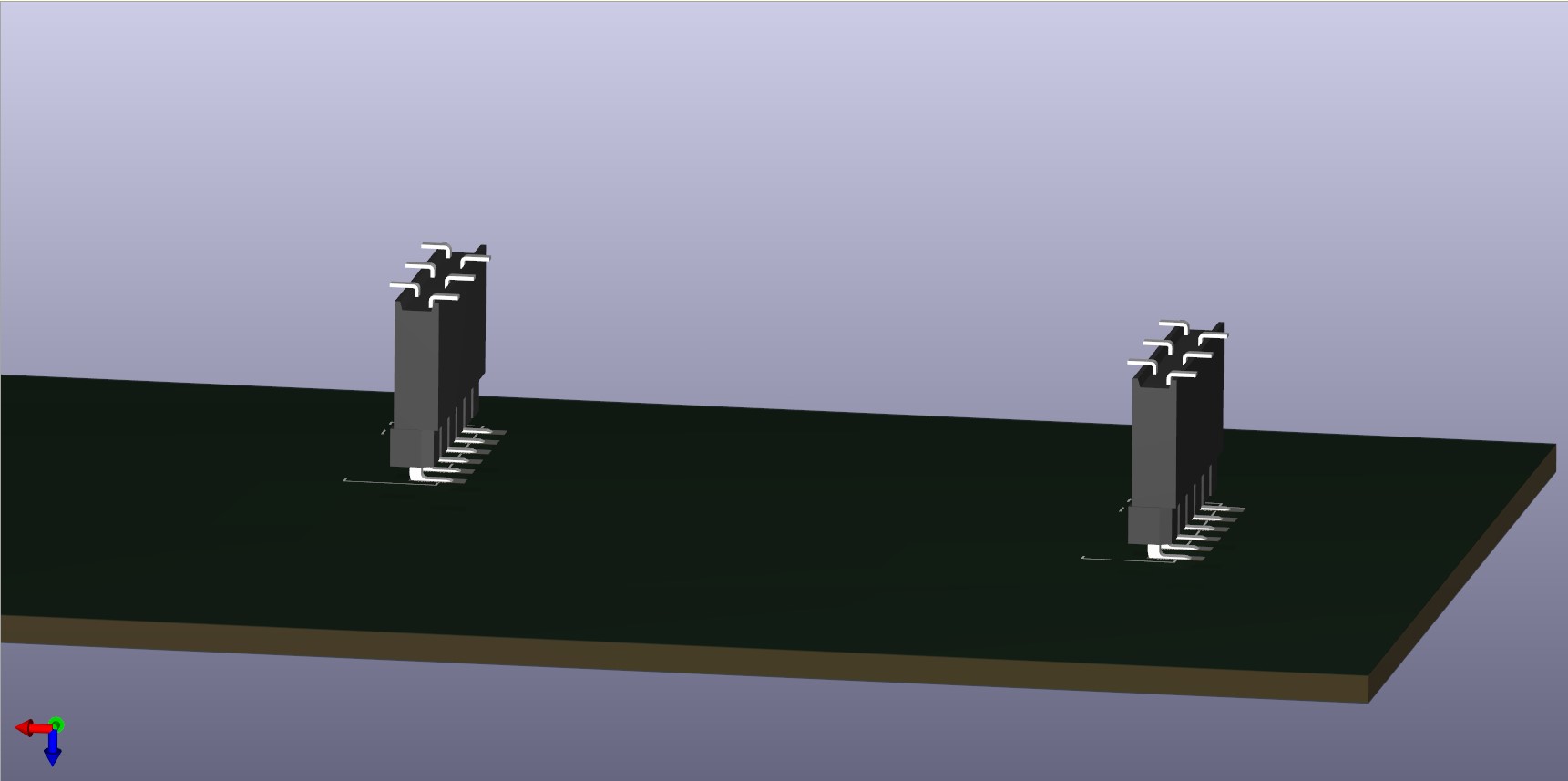
To make sure I align the male pins and female sockets of both PCBs, I copy and paste PCB layout from PCB mount and line it up on top of my DXF sketch. I then delete all the components apart from the pin sockets and lock it to prevent it from being removed when I update the design. Then I manualluy adjusted the position of the headers by looking at the 3D view to get the best possible alignment. Since the pads are long enough, minor adjustments can be made as long as the header is nearly on top of the sockets
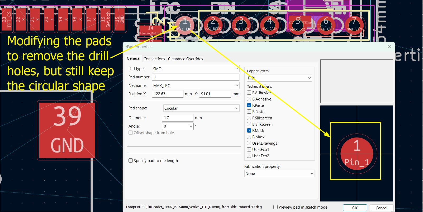
I then modified the Audio Amplifer Pads to be an SMD type
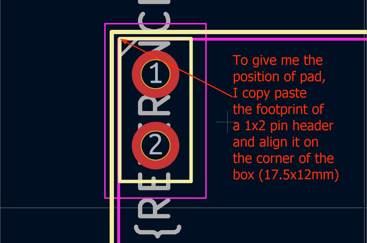
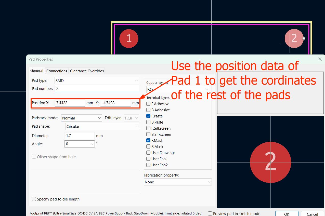
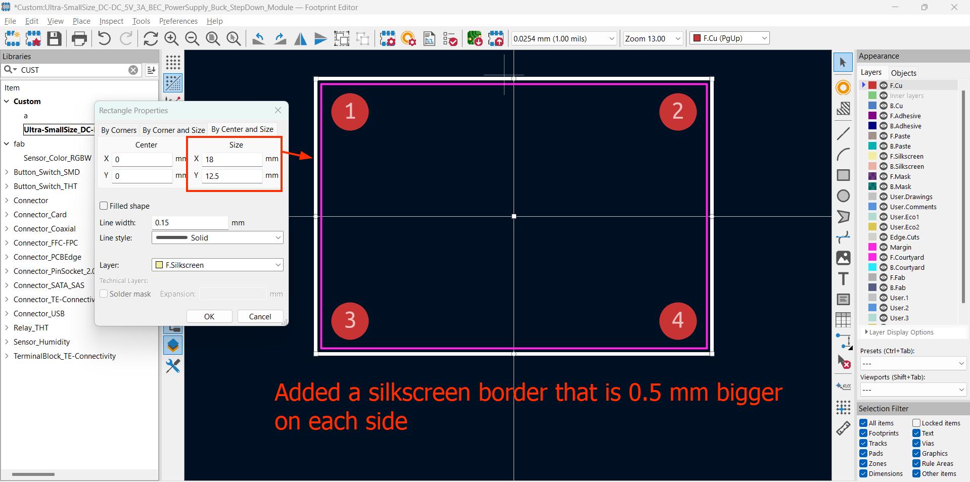
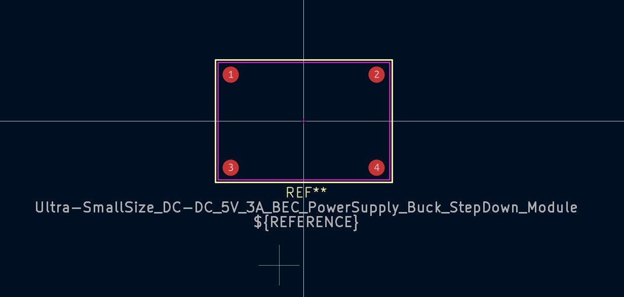
Since I did not find any datasheet for the BEC buck converter except external dimensions, I made an educated guess that since the module mostly likely uses 2.54 mm pitch header pins, the spacing of the holes will also be the same as other components like header pins.
Fabrication
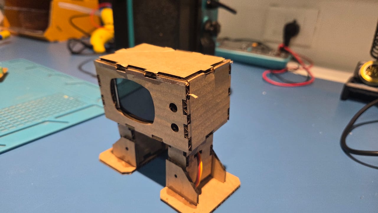
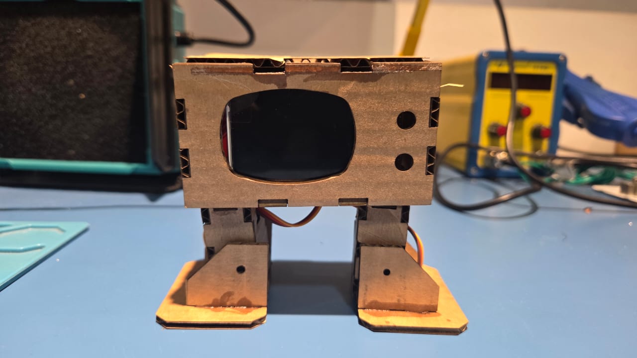
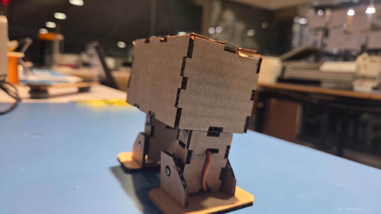
I was able to start fabrication and I sorted some issues with the servo leg. I was succesful in fully assembling one pair of servo upper leg and feet
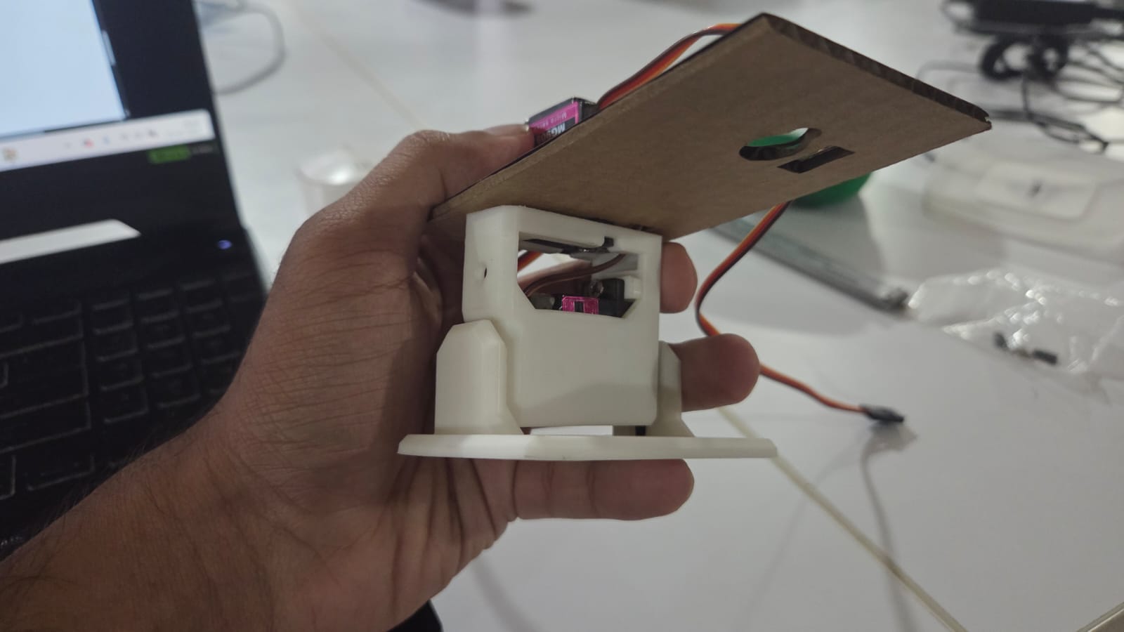
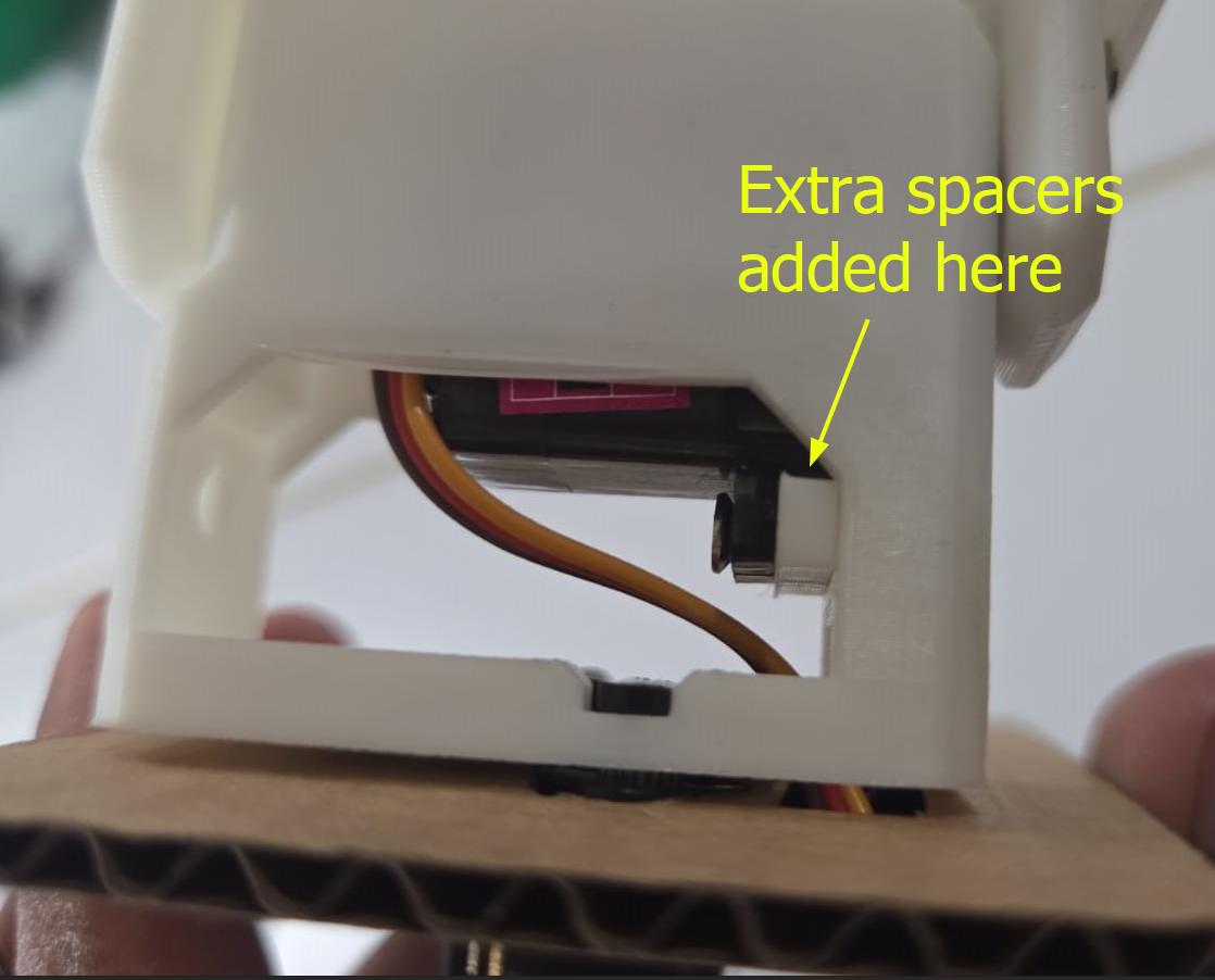
Once I corrected the issues with the first servo leg in CAD, I got a correct 3D print of the other leg This is how it looks once assembled
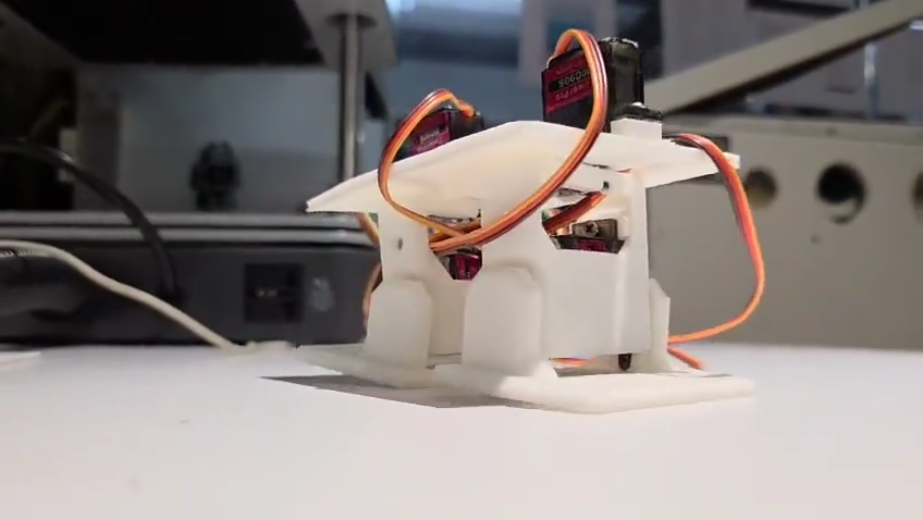
Then I proceeded to program a basic walk cycle before continuing with fabrication of the rest of the parts
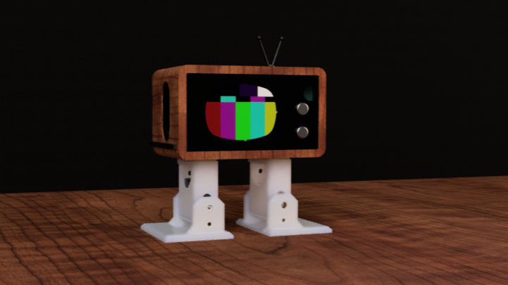
I 3D printed the TV Head in black PLA and the feaures in white, then I pressfit both of them together, and added a bit of superglue from behind to fix them together. I then used the vinyl cutter to add a wood-grain finish on the TV Head
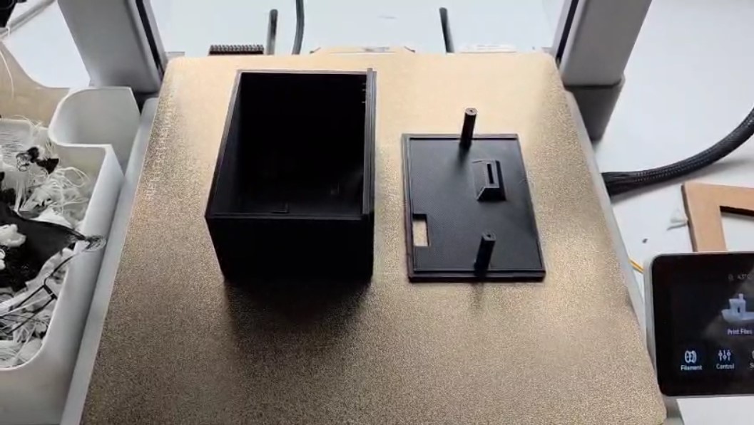
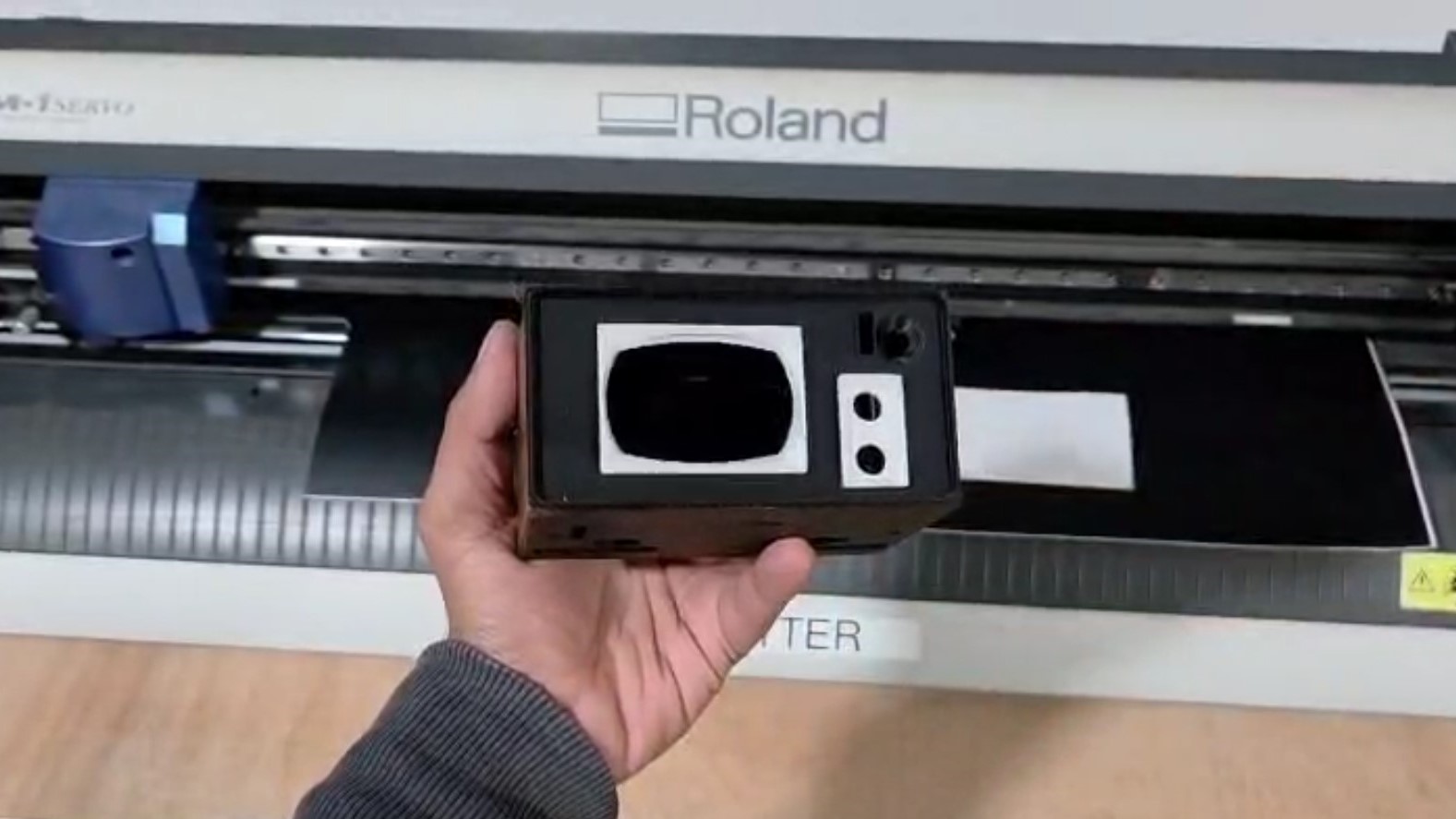
For detailing I used a wood grain vinyl sheet to wrap the TV Head enclosure
Programming a Walk Cycle
29/05/2025- I was not able to use the <Otto> library and its example
code due to a problem with the <SoftwareSerial.h> library. To speed
things up, I used the help of ChatGPT
Prompt 1: Generate Arduino code for 4-servo walking gait based on _execute function logic
Based on your `_execute()` function in Otto's library, here is an adapted Arduino code that uses oscillation for 4 servos to generate a walking gait:
 #include <ESP32Servo.h> #include <math.h>

        // Create servo objects
        Servo R2, R1, L2, L1; // Right Foot, Right Hip, Left Foot, Left Hip

        // Define servo pins
        int R2pin = D1;
        int R1pin = D2;
        int L1pin = D3;
        int L2pin = D4;

        // Oscillation parameters
        float amplitude[4] = {30, 30, 20, 20}; // Swing amplitude (degrees)
        float offset[4] = {0, 0, 4, -4}; // Neutral position offset
        float phase[4] = {0, 0, -PI/2, -PI/2}; // Phase difference (feet lag behind hips)
        int T = 1000; // One gait cycle in ms

        unsigned long startTime;

        void setup() {
        Serial.begin(9600);

        // Allocate all timers
        ESP32PWM::allocateTimer(0);
        ESP32PWM::allocateTimer(1);
        ESP32PWM::allocateTimer(2);
        ESP32PWM::allocateTimer(3);

        // Set frequency for each servo
        R2.setPeriodHertz(50);
        R1.setPeriodHertz(50);
        L1.setPeriodHertz(50);
        L2.setPeriodHertz(50);

        // Attach servos to pins
        R2.attach(R2pin, 1000, 2000);
        R1.attach(R1pin, 1000, 2000);
        L1.attach(L1pin, 1000, 2000);
        L2.attach(L2pin, 1000, 2000);

        // Center all servos at 90°
        R2.write(90);
        R1.write(90);
        L1.write(90);
        L2.write(90);

        delay(1000); // Give servos time to center
        startTime = millis();
        }

        void loop() {
        walkCycle(1.0); // One step
        delay(50); // Short delay before repeating
        }

        // --- Function to oscillate the servos in a step ---
        void walkCycle(float steps) {
        float t;
        float theta[4];
        unsigned long currentTime;

        while ((millis() - startTime) <= T * steps) {
        currentTime = millis();
        t = (currentTime - startTime) / float(T);

        for (int i = 0; i < 4; i++) {
        theta[i] = amplitude[i] * sin(2 * PI * t + phase[i]) + offset[i];
        }

        // Centered around 90°
        L1.write(90 + theta[0]);
        R1.write(90 + theta[1]);
        L2.write(90 + theta[2]);
        R2.write(90 + theta[3]);

        }

        startTime = millis(); // Reset time for next step
        }
- The hips (L1, R1) swing with 30° amplitude, feet (L2, R2) with 20° amplitude.
- Feet lag behind hip swing by 90° phase shift to simulate realistic stepping.
- Each servo oscillates around its center (90°), creating a walking pattern.
- This mimics the Otto _execute() and oscillateServos() logic in a simple standalone sketch.
                        #include <ESP32Servo.h>
                        #include <math.h>

                        // Create servo objects
                        Servo R2, R1, L2, L1; // Right Foot, Right Hip, Left Foot, Left Hip

                        // Define servo pins
                        int R2pin = D1;
                        int R1pin = D2;
                        int L1pin = D3;
                        int L2pin = D4;

                        // Oscillation parameters
                        float amplitude[4] = {30, 30, 20, 20};     // Swing amplitude (degrees)
                        float offset[4]    = {0, 0, 4, -4};        // Neutral position offset
                        float phase[4]     = {0, 0, -PI/2, -PI/2}; // Phase difference (feet lag behind hips)
                        int T = 1000;                              // One gait cycle in ms

                        unsigned long startTime;

                        void setup() {
                        Serial.begin(9600);

                        // Allocate all timers
                        ESP32PWM::allocateTimer(0);
                        ESP32PWM::allocateTimer(1);
                        ESP32PWM::allocateTimer(2);
                        ESP32PWM::allocateTimer(3);

                        // Set frequency for each servo
                        R2.setPeriodHertz(50);
                        R1.setPeriodHertz(50);
                        L1.setPeriodHertz(50);
                        L2.setPeriodHertz(50);

                        // Attach servos to pins
                        R2.attach(R2pin, 1000, 2000);
                        R1.attach(R1pin, 1000, 2000);
                        L1.attach(L1pin, 1000, 2000);
                        L2.attach(L2pin, 1000, 2000);

                        // Center all servos at 90°
                        R2.write(90);
                        R1.write(90);
                        L1.write(90);
                        L2.write(90);

                        delay(1000); // Give servos time to center
                        startTime = millis();
                        }

                        void loop() {
                        walkCycle(1.0); // One step
                        delay(50);      // Short delay before repeating
                        }

                        // --- Function to oscillate the servos in a step ---
                        void walkCycle(float steps) {
                        float t;
                        float theta[4];
                        unsigned long currentTime;

                        while ((millis() - startTime) <= T * steps) {
                            currentTime = millis();
                            t = (currentTime - startTime) / float(T);

                            for (int i = 0; i < 4; i++) {
                            theta[i] = amplitude[i] * sin(2 * PI * t + phase[i]) + offset[i];
                            }

                            // Centered around 90°
                            L1.write(90 + theta[0]);
                            R1.write(90 + theta[1]);
                            L2.write(90 + theta[2]);
                            R2.write(90 + theta[3]);
                        }

                        startTime = millis(); // Reset time for next step
                        }
Conclusion
Notes for the Future
Add Mistakes only in Mistakes and Solutions section to avoid break in flow
References
References to help reader understand in detail
Look at previous year documentation