Week 15: System Integration
Objectives
- Individual Assignment: Design and document the system integration for your final project
Individual Assignment
Final Project Features
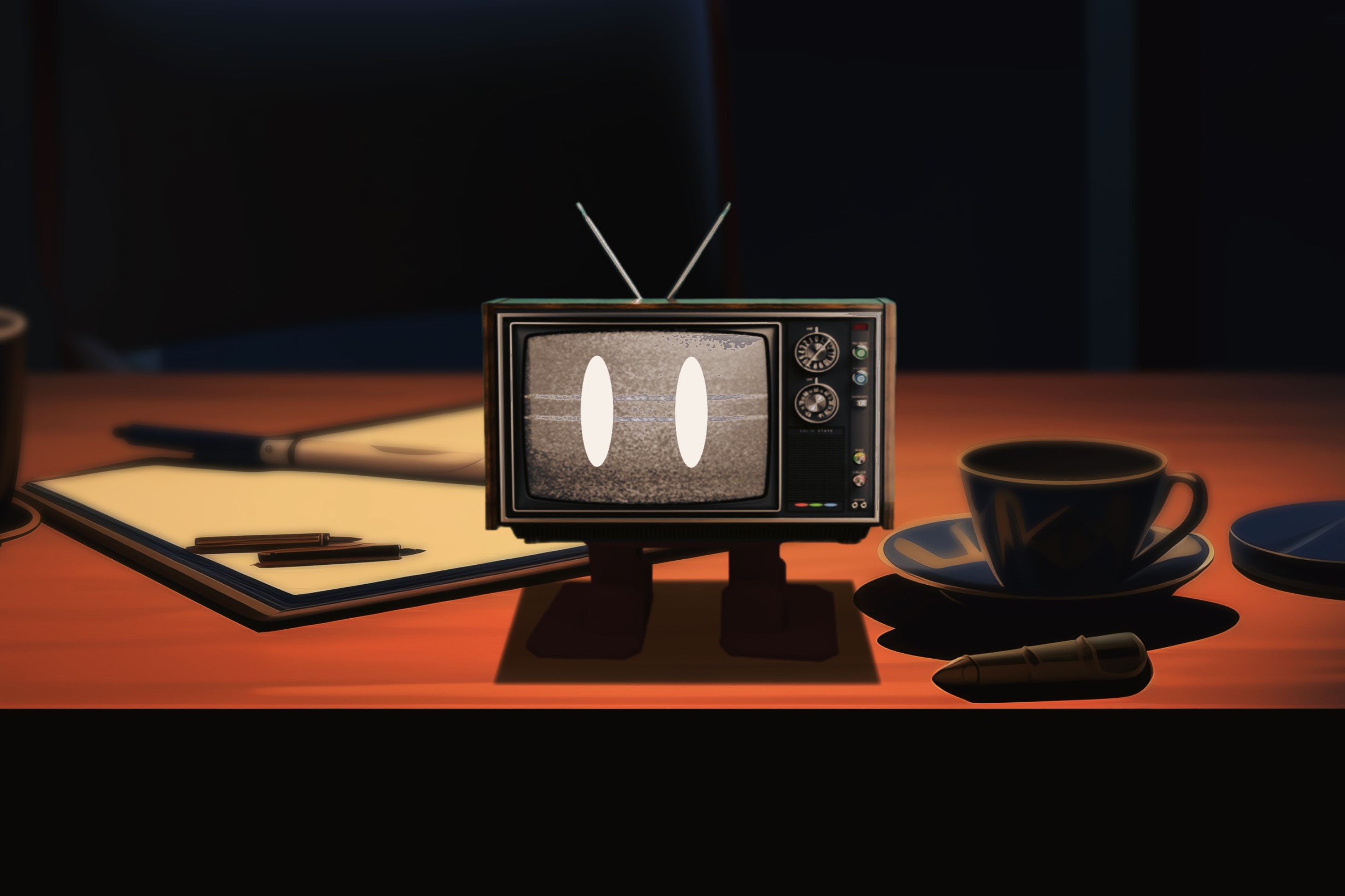
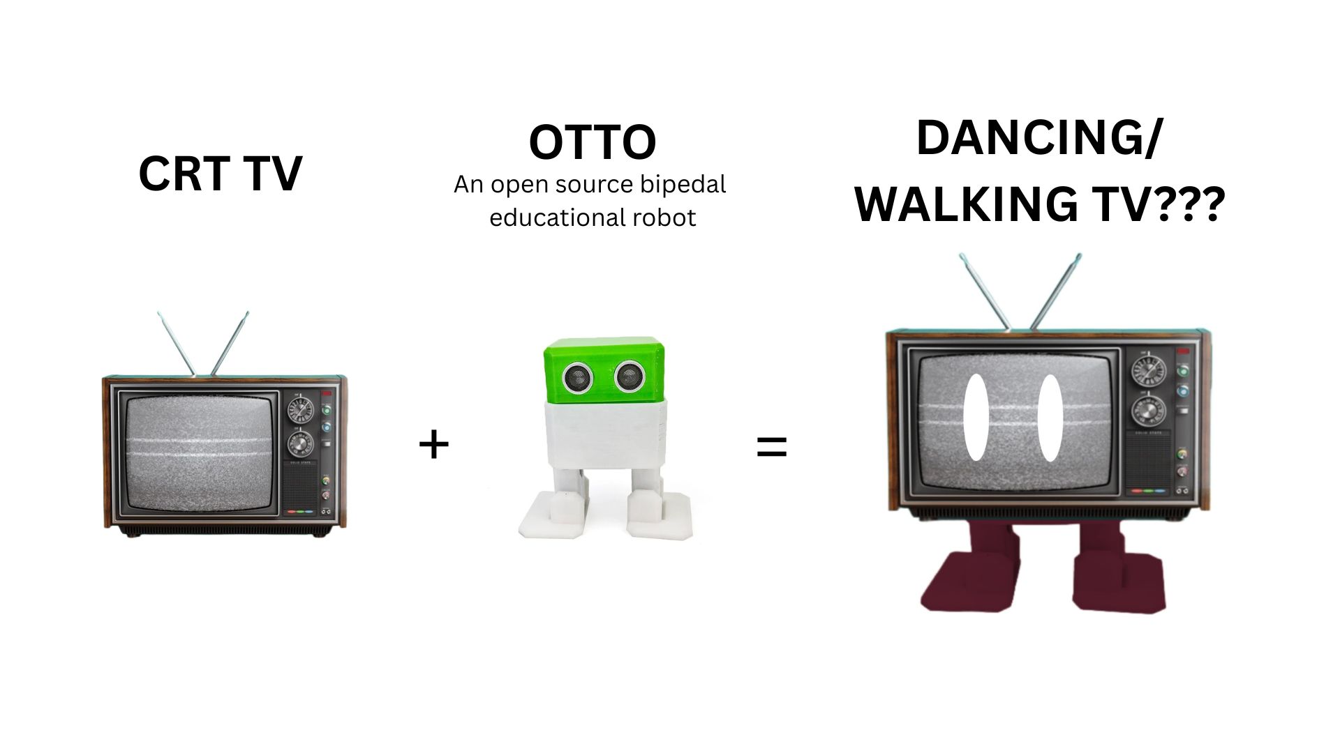
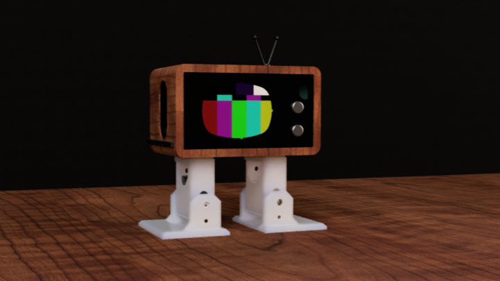
My project is called 'Lumi'. Essentially it is a walking TV.
Lumi has the following key features, which have been arranged in order here
- Lumi can detect if the user comes closer than 2m to it.
- When the user is farther than 2m, Lumi behaves like a living being
- Lumi 'shuffle' walks just like Otto
- Lumi plays facial animations randomly
- Sound effects corresponding to animations will also play
- When the user is closer than 2m, Lumi 'realizes' it is being watched, it then starts behaving like a regular TV
- Lumi stops moving
- It starts playing TV footage
- Accompaning sound effects will be playes from its speakers
To read more, please go to the Final Project Page
Exploded View
We had a class on system integration from Kalyani (FA'25), and I drew an exploded view of my final project as part of an assignment. The exploded view shows how different components will be integrated together and the physical space each of them will occupy in the final design
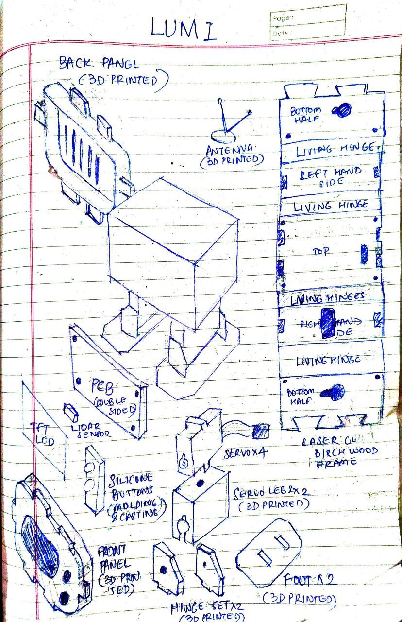
Point to note here is that I have since added a speaker to the list of output devices and abandoned lasercutting wooden frame based on results I got while testing.
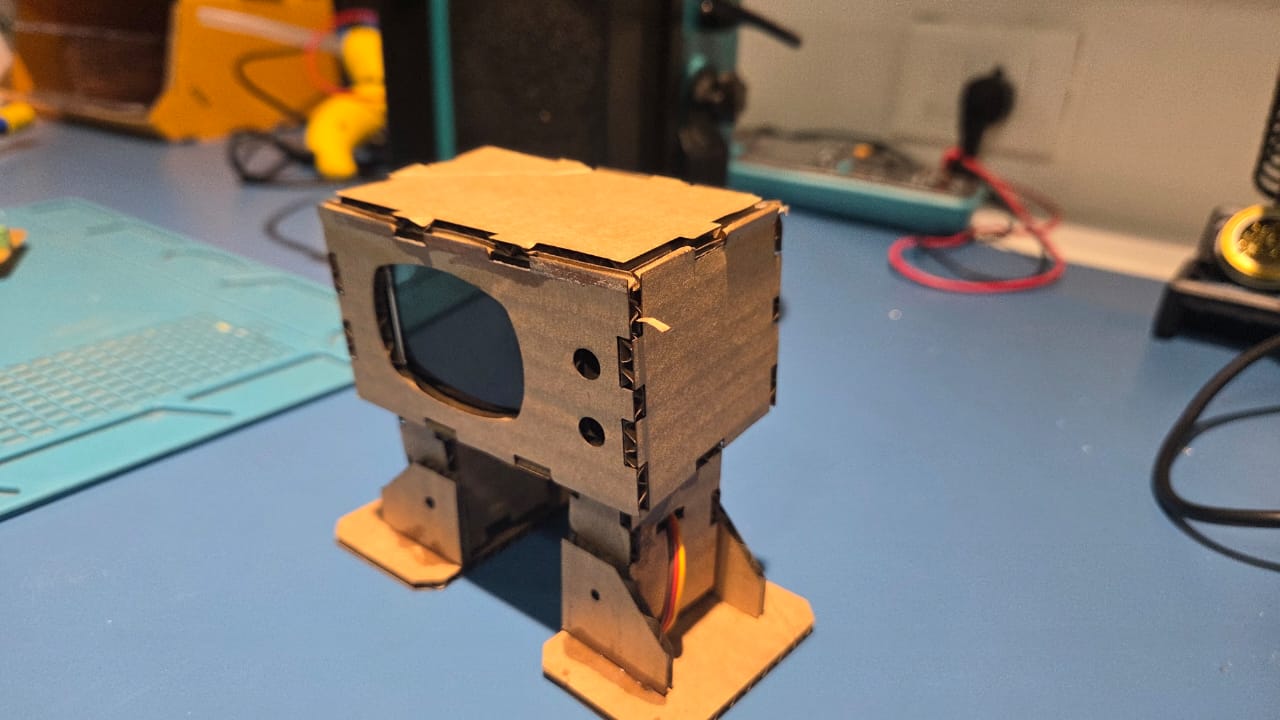
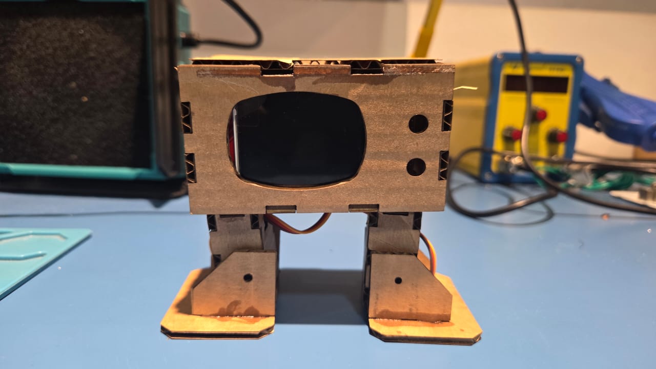
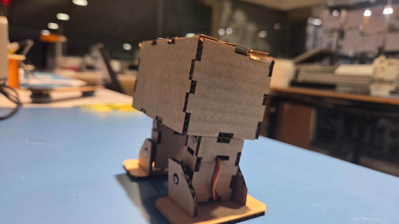
Making a Cardboard Mockup
To visualize my design a bit better, I had made a mockup of my final design, I also incorporated my TFT display and servos into it, as they are the biggest parts of the electronics I need
To make my work a bit easier I used Boxes.py, which is an Open Source box generator written in Python. The designs for Otto has already been uploaded in Boxes.py,so all I have to do is adjust the parameters related to number of pads and spacing between them to be able to get an easily assemblable design
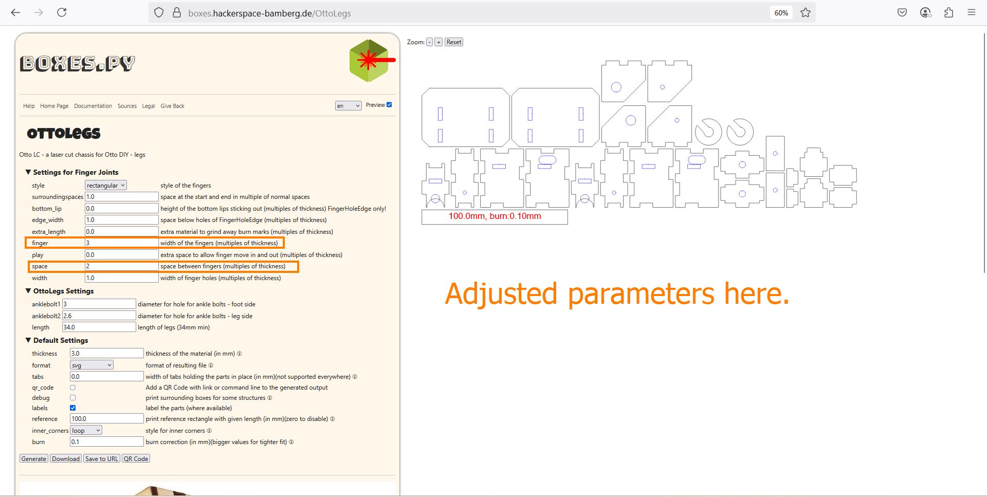
I then import the SVG file as a sketch into Fusion and extrude it to ccreate multiple bodies.
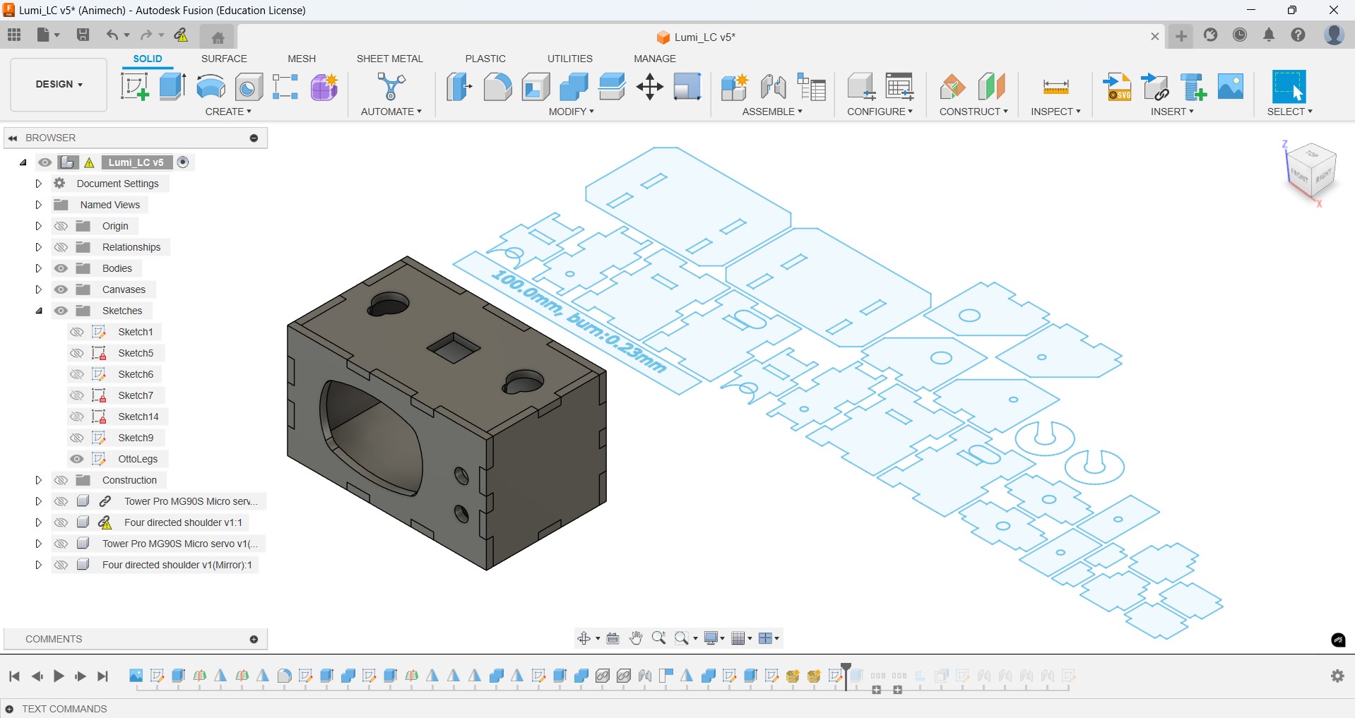
Then I arranged all the bodies using the Arrange feature.
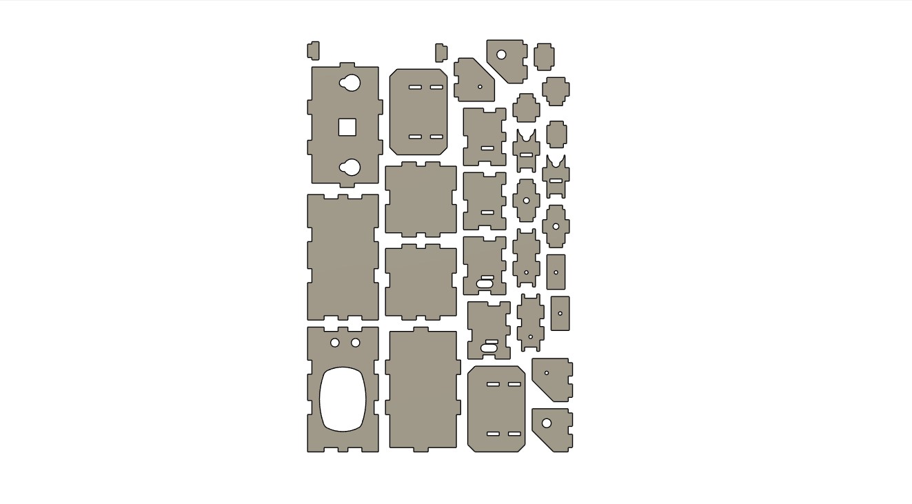
Once I made the lasercut mockup, and tried fitting in some electronics, I realized that I would require more space inside. I plan to achieve this by increasing the 'depth' of my TV head.
User Flow Diagram
Based on instructor Saheen's advice, I created a user flow diagram using Draw.io.
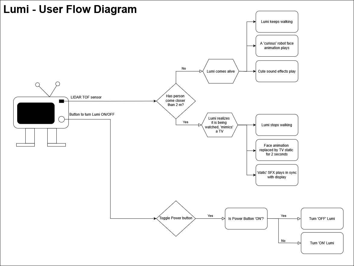
Each feature has been ordered according to order of priority:
- The TV should be able to switch between 'alive' and 'regular TV' modes in response to input from the time-of-flight sensor
- Sound effects should be played in sync with both these modes
- Lumi should be able to walk around and stop based on these two modes
Download the .drawio file here
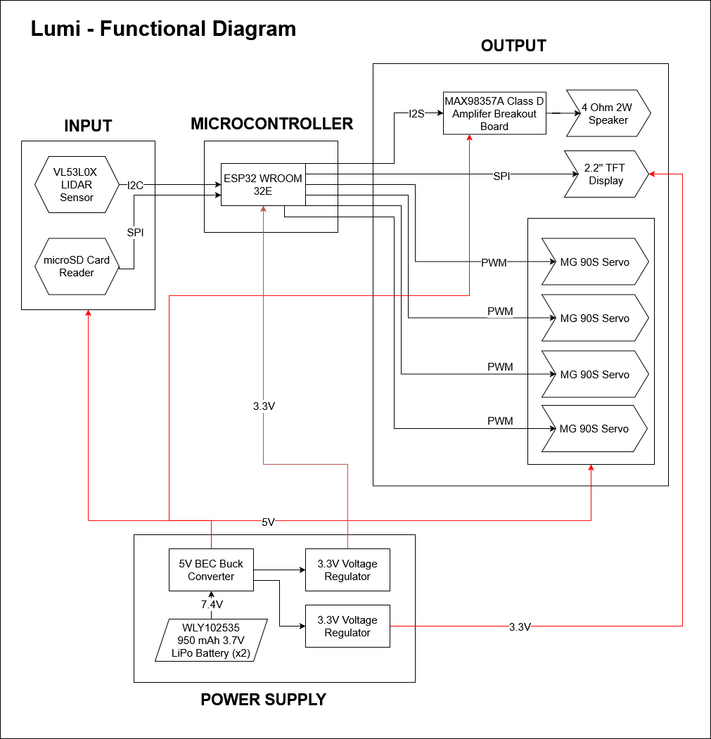
Functional Flow Diagram
Based on instructor Saheen's advice, I created a functionality flow diagram using Draw.io.
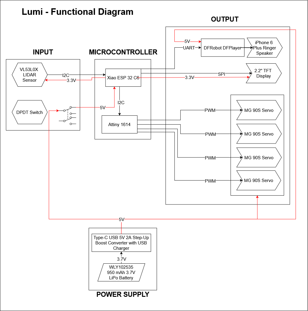
A note on some elements of the functionality diagram
- A buck converter is used to provide a step down voltage of 5V. A voltage regulator would be much more likely to fail in this scenario due to overheating
- Two different voltage regulators are used to keep voltage supply to the ESP32 seperate from other current drawing electronics
- When testing the ESP32 for library conflicts, I, with the help of my instructorSaheen was able to
identify that the
<Audio.h>library is very heavy. In combination with other libraries, around 73% of memory space was used up just to load the libraries. I used an alternate library calledESP8266Audio, importing specific header files within it based on programming work done by Revi (FA'25) for a simiplar application. This saved a lot of space. If problems persist during programming, I will have to switch to using 2 microcontrollers, one dedicated to playing audio
Download the .drawio file here
Packaging the Electronics using CAD
Intially I wanted to use ESP32-WROOM32 E and some other electronic components. The plan was to use two PCBs stacked on top of each other since I was unsuccessful at fitting all the electronics in one PCB. The larger PCB would single sided and will attached to TFT display and other through hole components and the battery on the other side. A smaller PCB will will be stacked behind it using pin headers. This PCB can be double sided if required, and it will house the microSD card slot, the USB-C-type breakout board, and the ESP32 WROOM 32E and some other smaller SMD components.
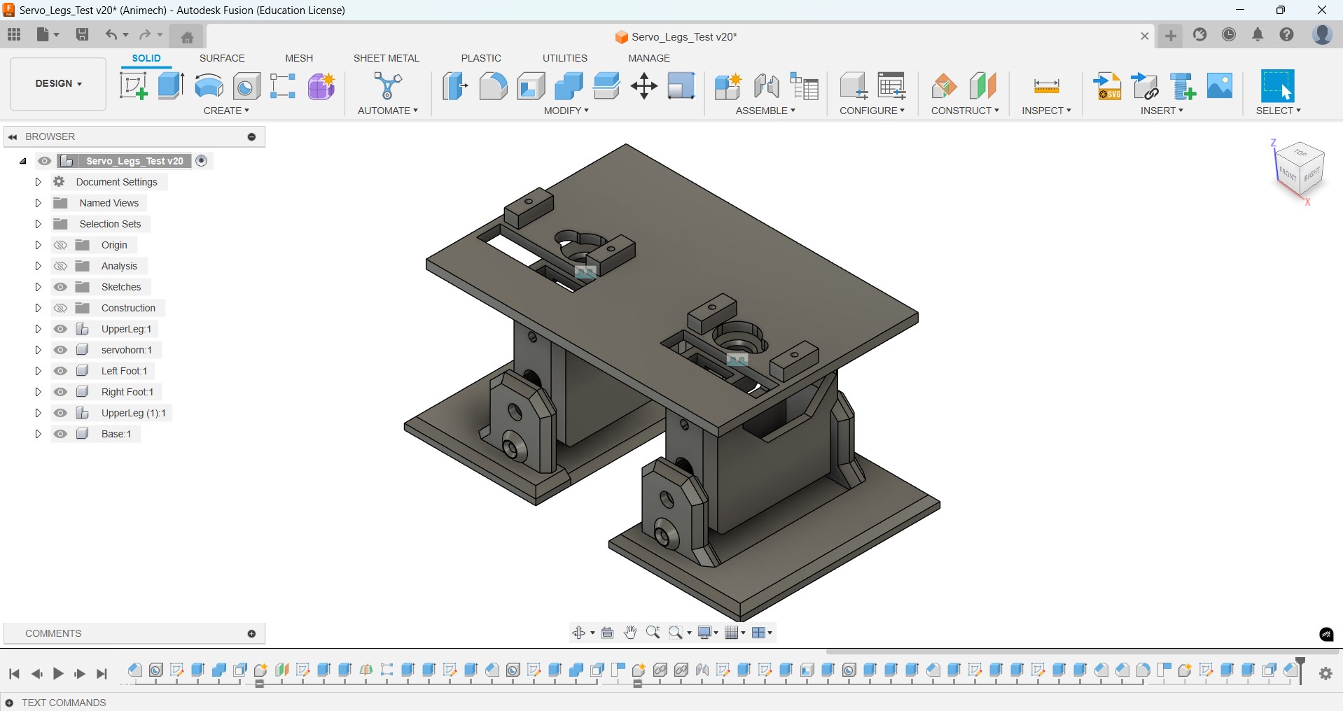
Also, I downloaded the STEP files of OTTO and used that as a reference to design my walking mechanism in Fusion, accommodating for changes in:
- the servo mount height
- the size of the servo horns
- changed position of the servos
As for aesthetics, I wanted it be small and cute. Initally I opted for a more rounded design to achieve this effect, but later on I changed it to more hard edges since old TVs had more hard edges rather than rounded corners
But I had to start from scratch and simplify my design by reducing the components since I faced a lot of difficulties in routing traces for the PCB. After some iterations this is how how the system integration of the Electronics would look like.
Then I made a CAD design showing how the inner electronics will be assembled. The screw holes will be used to mount each component
Wiring
- Since I had two boards, I planned to use 2x2 IDC connectors and ribbon cables to connect the two boards together.
- For attaching the LIDAR TOF sensor, I used the same ribbon cable and soldered the ends to the PCB
- The servo cables were left as is and connecte to 1x3 pin sockets on the Servo Legs PCB
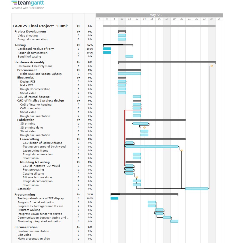
Scheduling
Based on my finalised Functionality diagram, I finalised the schedule of my final project using Team Gantt a gantt chart maker I found online, but I faced challenges in adhering to the timelines I have set for myself.
Updating the BOM
Based on my finalised Functionality diagram, I finalised the BOM of my final project and have begun the procurement process
| Srl. No. | Item | Description | Unit Cost (Rs.) | Quantity (g/nos) | Total Cost (Rs.) |
|---|---|---|---|---|---|
| 1 | Wood Grain Vinyl Wrap | For detailing | 0.0003827 | 1 | 0.3827 |
| 2 | eSun PLA+ White | 3D printing filament | 44.25 | 1.3 | 57.525 |
| 3 | eSun PLA+ Black | 3D printing filament | 79.74 | 1 | 79.74 |
| 4 | M2×5 mm SS CSK Countersunk Philips Head Bolt | To screw lid in place with rest of the TV Head | 8.2 | 1 | 8.2 |
| 5 | FR1 Copper Clad - Single Sided | For old TV board | 100 | 1 | 100 |
| 6 | 2 pin JST PH 2 mm SMT Header Horizontal Right Angle Side Entry | For Servo Legs Driver board, minimum 89x24 mm | 3 | 2 | 6 |
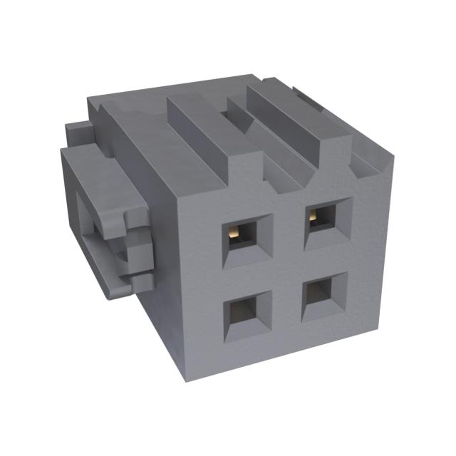
| 7 | Connector Header SMD 4 POS 2.54 mm 2x2 | To connect to speaker | 32 | 3 | 96 |
| 8 | 4 Position Rectangular Receptacle Connector IDC Gold 28-30 AWG | Connectors that have to be crimped onto flat ribbon cable | 81.78 | 2 | 163.56 |
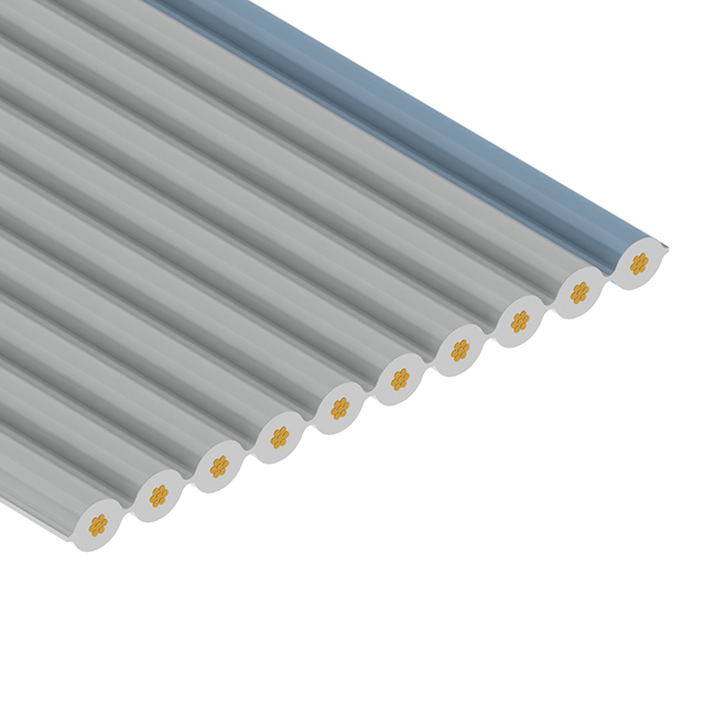
| 9 | Flat Ribbon Cable Gray 10 Conductors 0.025" (0.64mm) Flat Cable 50.0" (1.25.4cm) 10×2 | Should have 4 minimum wires and be compatible with IDC connectors | 187.5 | 1 | 187.5 |
| 10 | PinSocket (10x2) 2.54 mm Vertical SMD | 25 | 2 | 50 | |
| 11 | Xiao ESP32 C3 | Microcontroller for the TV driver board | 583 | 1 | 583 |
| 12 | VL53L0X TOF Based LiDAR Laser Distance Sensor | To sense when you get close | 169 | 4 | 676 |
| 13 | 2.2" ILI9341 driver TFT Display | Display that will be programmed to look like an old TV screen | 344 | 1 | 344 |
| 14 | 6 Pin Square Tactile DDPDT Push Button Switch (6.8mm×6.8mm) | For powering ON/OFF the circuit | 3.23 | 1 | 3.23 |
| 15 | Apple iPhone 6 Loud Speaker | Speaker | 297 | 2 | 594 |
| 16 | DFRobot DFPlayer | Mini MP3 Player with microSD card slot for sound | 629 | 1 | 629 |
| 17 | 16 GB class 4 micro SD Card | ESP32 can read 2MB/second, can be satisfied by class 4 card, recommended to be in FAT32 format | 280 | 1 | 280 |
| 18 | WLY102535 950 mAh 3.7V LiPo battery | For charging | 399 | 2 | 798 |
| 19 | Type-C USB to 5V 2A Step-Up Boost Converter with USB Charger | Integrated charger circuit and boost converter to 5V | 88 | 1 | 88 |
| 20 | Attiny 1614 | Microcontroller for the Servo driver for the legs | 237 | 1 | 237 |
| 21 | MG90S mini Servos | Motors for the legs | 113 | 4 | 452 |
| 22 | TXB0108PWR SOIT 23 | ICs level shifter 200 mA max per i/o for logic level shifter for I2C/sensors | 61 | 1 | 61 |
| 23 | Resistor 10k Ohm | For logic level operation | 0.5 | 2 | 1 |
| 24 | 10 uF capacitor | Decoupling capacitor to protect the Attiny 1614 | 2 | 2 | 4 |
| 25 | 100 nF capacitor | To save voltage spikes in servo motion | 0.18 | 4 | 0.72 |
| 26 | AN431 voltage regulator 3.3 V 100mA LDO | To provide 3.3 V for logic level shifter | 4 | 2 | 8 |
| 27 | 0 ohm resistor | To bridge two traces that are difficult to connect otherwise | 0.0375 | 2 | 0.075 |
| 28 | Connector Header SMD 6 POS 2.54 mm 2x3 | To connect to 4 sensors | 12.75 | 2 | 25.5 |
| 29 | Connector FHD pin header 01x06, 2.54 mm Horizontal SMD | 0 | 1 | 0 | |
| 30 | ProshPlay Type C CH340C Auto UPDI FTDI Converter | A FTDI to UPDI converter that we used to serially program the Attiny 1614 | 212 | 1 | 212 |
| Purchase Cost (INR) | 15664.87 | ||||
| Inventory Cost (INR) | 18248.22 | ||||
| Total Cost (INR) | 50262.70707 | ||||
| Total Cost (USD) | 602.9849412 | ||||
To convert the below given screenshot into an HTML table using the help of ChatGPT. The excel sheet can be downloaded from Design Files
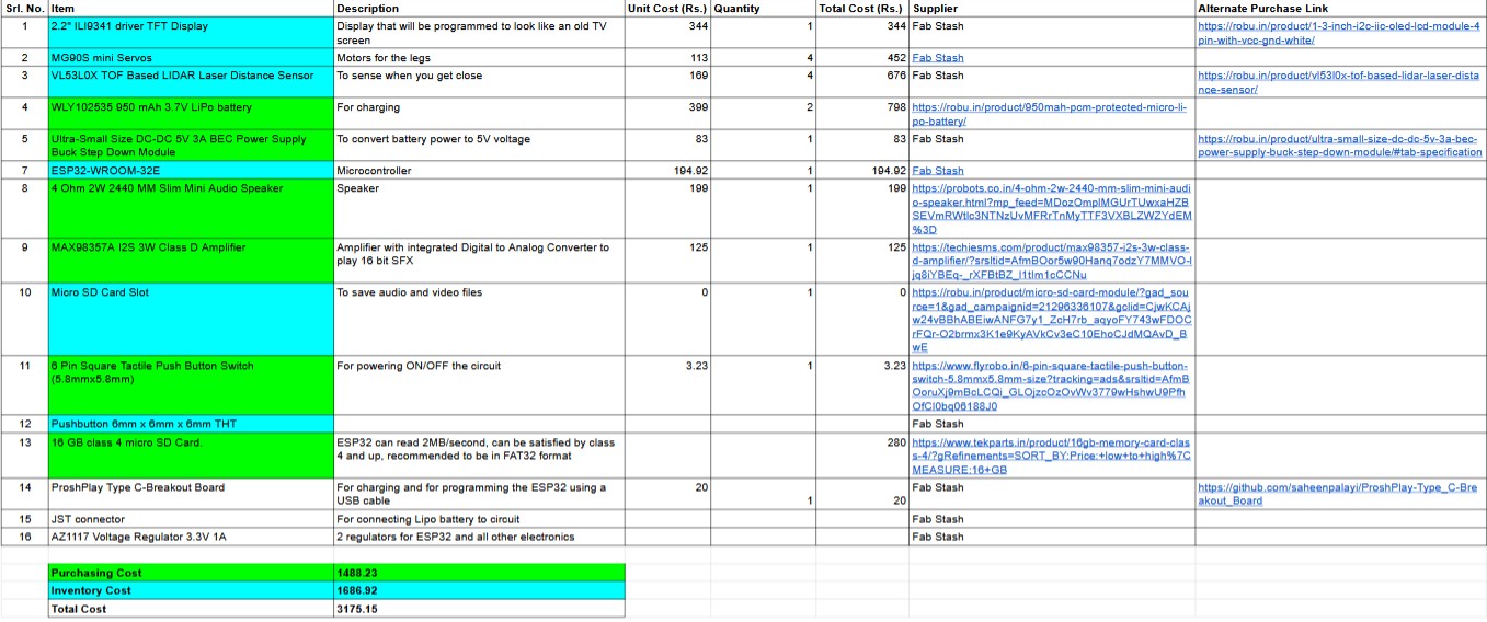
Prompt 1 : Convert this page to an HTML table without 'Supplier and Alternate Supplier columns
Convert this page to an HTML table without 'Supplier and Alternate Supplier columns
HTML Table Output
<table border="1">
  <thead>
    <tr>
      <th>Srl. No.</th>
      <th>Item</th>
      <th>Description</th>
      <th>Unit Cost (Rs.)</th>
      <th>Quantity</th>
      <th>Total Cost (Rs.)</th>
    </tr>
  </thead>
  <tbody>
    <tr><td>1</td><td>2.2" ILI9341 driver TFT Display</td><td>Display that will be programmed to look like an old TV screen</td><td>344</td><td>1</td><td>344</td></tr>
    <tr><td>2</td><td>MG90S mini Servos</td><td>Motors for the legs</td><td>113</td><td>4</td><td>452</td></tr>
    <tr><td>3</td><td>VL53L0X TOF Based LIDAR Laser Distance Sensor</td><td>To sense when you get close</td><td>169</td><td>4</td><td>676</td></tr>
    <tr><td>4</td><td>WLY-102535 950 mAh 3.7V LiPo battery</td><td>For charging</td><td>399</td><td>2</td><td>798</td></tr>
    <tr><td>5</td><td>Ultra-Small Size DC-DC 5V 3A BEC Power Supply Buck Step Down Module</td><td>To convert battery power to 5V voltage</td><td>83</td><td>1</td><td>83</td></tr>
    <tr><td>6</td><td>ESP32-WROOM-32E</td><td>Microcontroller</td><td>194.92</td><td>1</td><td>194.92</td></tr>
    <tr><td>7</td><td>4 Ohm 2W 2440 MM Slim Mini Audio Speaker</td><td>Speaker</td><td>199</td><td>1</td><td>199</td></tr>
    <tr><td>8</td><td>MAX98357A I2S 3W Class D Amplifier</td><td>Amplifier with integrated Digital to Analog Converter to play 16 bit SFX</td><td>125</td><td>1</td><td>125</td></tr>
    <tr><td>9</td><td>Micro SD Card Slot</td><td>To save audio and video files</td><td>0</td><td>1</td><td>0</td></tr>
    <tr><td>10</td><td>8 Pin Square Tactile Push Button Switch (6.8mm×6.8mm)</td><td>For powering ON/OFF the circuit</td><td>3.23</td><td>1</td><td>3.23</td></tr>
    <tr><td>11</td><td>Pushbutton 6mm × 6mm × 6mm THT</td><td></td><td>0</td><td>1</td><td>0</td></tr>
    <tr><td>12</td><td>16 GB class 4 micro SD Card</td><td>ESP32 can read 2MB/second, can be satisfied by class 4 and up, recommended to be in FAT32 format</td><td>280</td><td>1</td><td>280</td></tr>
    <tr><td>13</td><td>ProshPlay Type-C Breakout Board</td><td>For connecting and for programming the ESP32 using a USB cable</td><td>20</td><td>1</td><td>20</td></tr>
    <tr><td>14</td><td>JST connector</td><td>For connecting Lipo battery to circuit</td><td>0</td><td>1</td><td>0</td></tr>
    <tr><td>15</td><td>AZ1117 Voltage Regulator 3.3V 1A</td><td>2 regulators for ESP32 and all other electronics</td><td>0</td><td>1</td><td>0</td></tr>
  </tbody>
  <tfoot>
    <tr><td colspan="5"><strong>Purchasing Cost</strong></td><td>1488.23</td></tr>
    <tr><td colspan="5"><strong>Inventory Cost</strong></td><td>1686.92</td></tr>
    <tr><td colspan="5"><strong>Total Cost</strong></td><td>3175.15</td></tr>
  </tfoot>
</table>
Programming Logic
This section has been updated after Fab Academy to provide a better overview of the programming logic of both boards
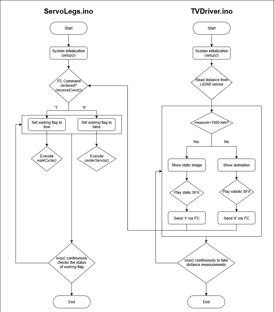
Download the .drawio file here
Conclusion
This week I learnt a couple of techniques that can help with integrating multiple systems together. These include making cardboard mockups, drawing an exploded view of my design, and making user flow and functional diagrams.
Future Outlook
- Keep electronics and mechanical design seperate but linked to each other:A better approach to CAD system integration is to keep the mechanical aspect and the electronics in seperate files that are linked to each other. This keeps the design workspace clutter free while still maintaining the ease of making design changes.
- Stacking PCBs:The larger PCB is single sided and will attached to TFT display and other through hole components and the battery on the other side. A smaller PCB will will be stacked behind it using pin headers. This PCB can be double sided if required, and it will house the microSD card slot, the USB-C-type breakout board, and the ESP32 WROOM 32E and some other smaller SMD components.
- Testing library support and storage space on your microcontroller:Testing if the various libraries conflict with each other or if there is enough space before finalising the choice of microcontroller, is very important.
References
References to help reader understand in detail
Design Files
Click here to access the design files