Project Development
This week, I focused on designing, fabricating, and assembling a custom PCB. I used KiCad for schematic and PCB design, then fabricated the board using milling and laser etching, and finally assembled and tested it.
Bluetooth Speaker Test
I tested the Bluetooth speaker functionality using an ESP32. The ESP32 connects to a smartphone via Bluetooth, allowing audio playback through the speaker.
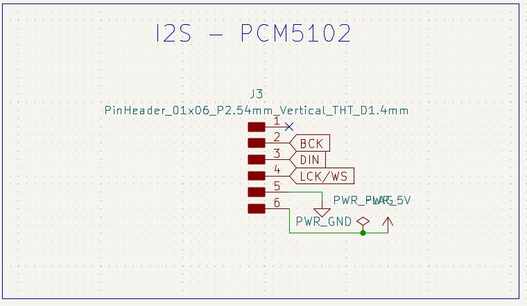
For the ESP32 to output analog audio you need to connect an I2S DAC which converts the I2S Digital Audio Signals to Analog Output and an amplifier and speaker to get the output. In the software side, we need the 'Audio Tools' and BluetoothA2DPSink Libraries
- Audio Tools - I2S
- BluetoothA2DPSink - Bluetooth Audio Sink
Here is the code to test the Bluetooth speaker functionality using ESP32:
#include "AudioTools.h"
#include "BluetoothA2DPSink.h"

I2SStream i2s;
BluetoothA2DPSink a2dp_sink(i2s);

void setup() {
    auto cfg = i2s.defaultConfig();
    cfg.pin_bck = 13;
    cfg.pin_ws = 14;
    cfg.pin_data = 12;
    i2s.begin(cfg);

    a2dp_sink.start("Symphoni");
}

void loop() {
}
I tested the Bluetooth speaker with a smartphone, playing audio through the speaker. The ESP32 connects to the smartphone via Bluetooth, allowing audio playback. You can check the documetnation for Week 10: Output Devices to know more about I2S, DAC and Amplifier.
App interface
I developed a simple Android app to write the NFC tags and also to control playback. The app allows users to play/pause audio, next and previous, and adjust volume. It uses the http communication using WiFi for communication with the ESP32, which communicates with Spotify WebAPI. The app is developed using Dart(Flutter) in Android Studio.
The documentation for the app development can be seen in the Week 14: Interface and Application Programming assignment.
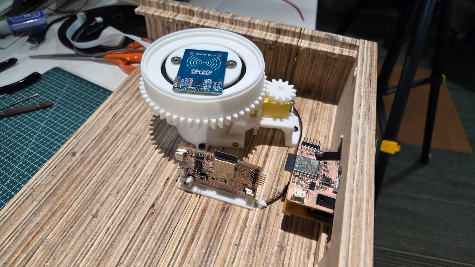
App and Turntable Test
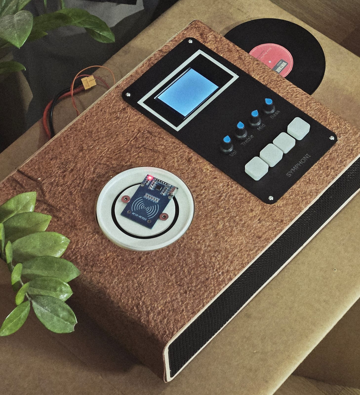
I tested the app with the cardboard turntable. The turntable allows users to control playback by placing NFC tags on it. The app communicates with the ESP32 to play specific tracks based on the NFC tags scanned. I tested this in the Week 14: Interface and Application Programming assignment. I used my board that I made in the Network and Communication Week
When the NFC tag is detected by the RFID reader module, it sends the Spotify URI to the Spotify Web API which starts playback and also I have written a code to drive the motor using analogWrite.
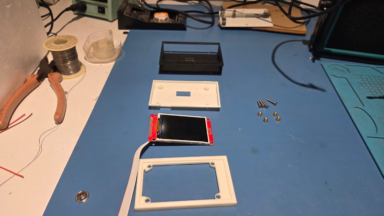
Display Test
I tested the 2.8-inch SPI TFT display with the ESP32. The display is powered by the ESP32 and communicates via SPI.
Here, I am running the test code provided in the examples of TFT_eSPI library for 320x240. The example code 'TFT_Meters.ino' is linked here
I need to test the album cover image and URL fetching and displaying on the board.
Draft Slide and Video
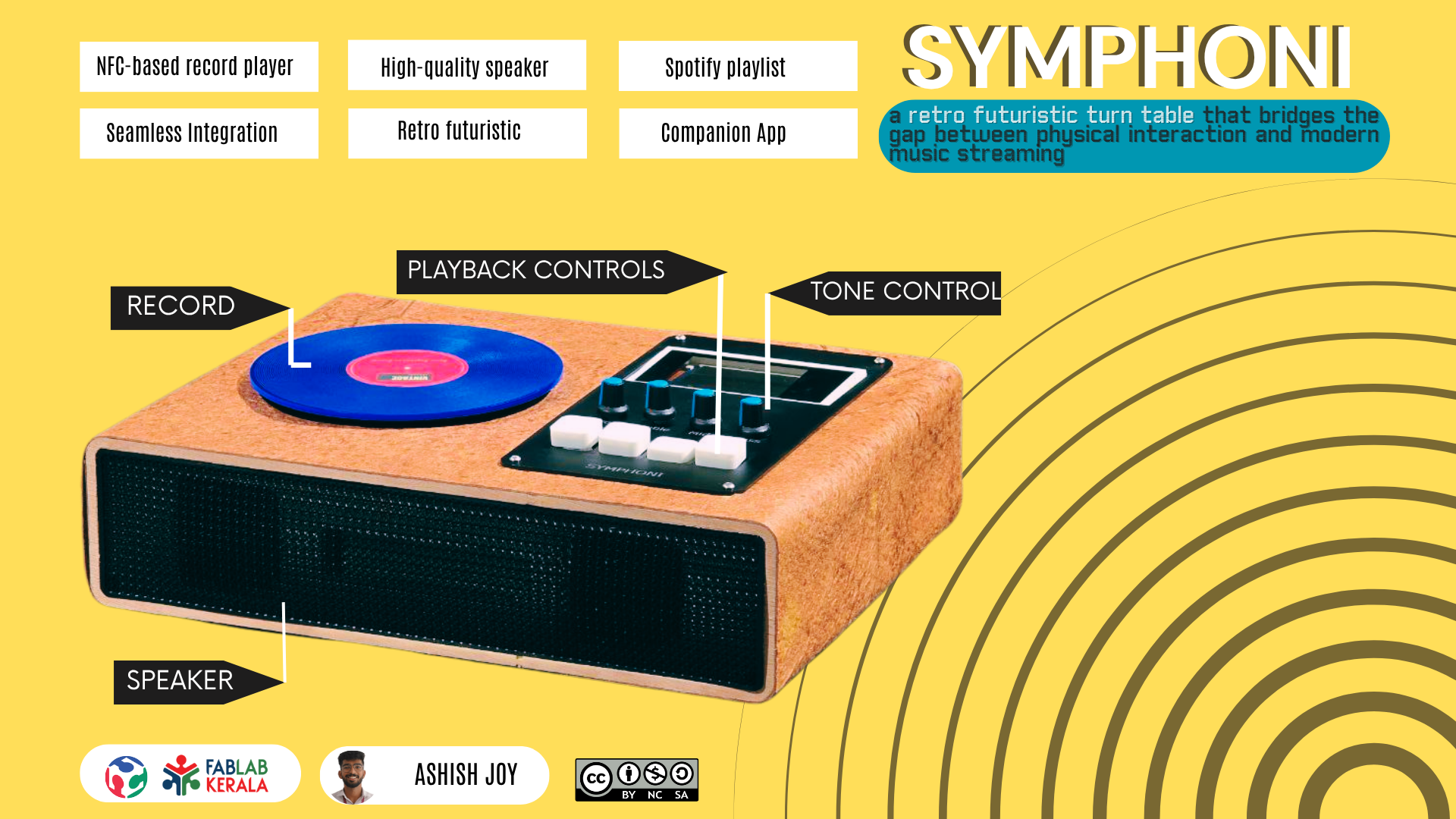
I made the draft slide and video using Canva.
The slide is made using Canva, which is a user-friendly design tool that allows users to create professional-looking presentations and graphics. The slide acts just as a draft for the final presentation, showcasing the key features and functionalities of the Symphoni project.
Canva VideoThe presentation slide and the presesntation video have certain criterias for the presentation.
The presentation slide should be of the dimensions 1920x1080 pixels, which is the standard size for high-definition presentations. The slide should be named "presentation.png" and should be in PNG format. The video should be of the dimensions 1920x1080 pixels, which is the standard size for high-definition videos. The video should be named "presentation.mp4" and should be in MP4 format.
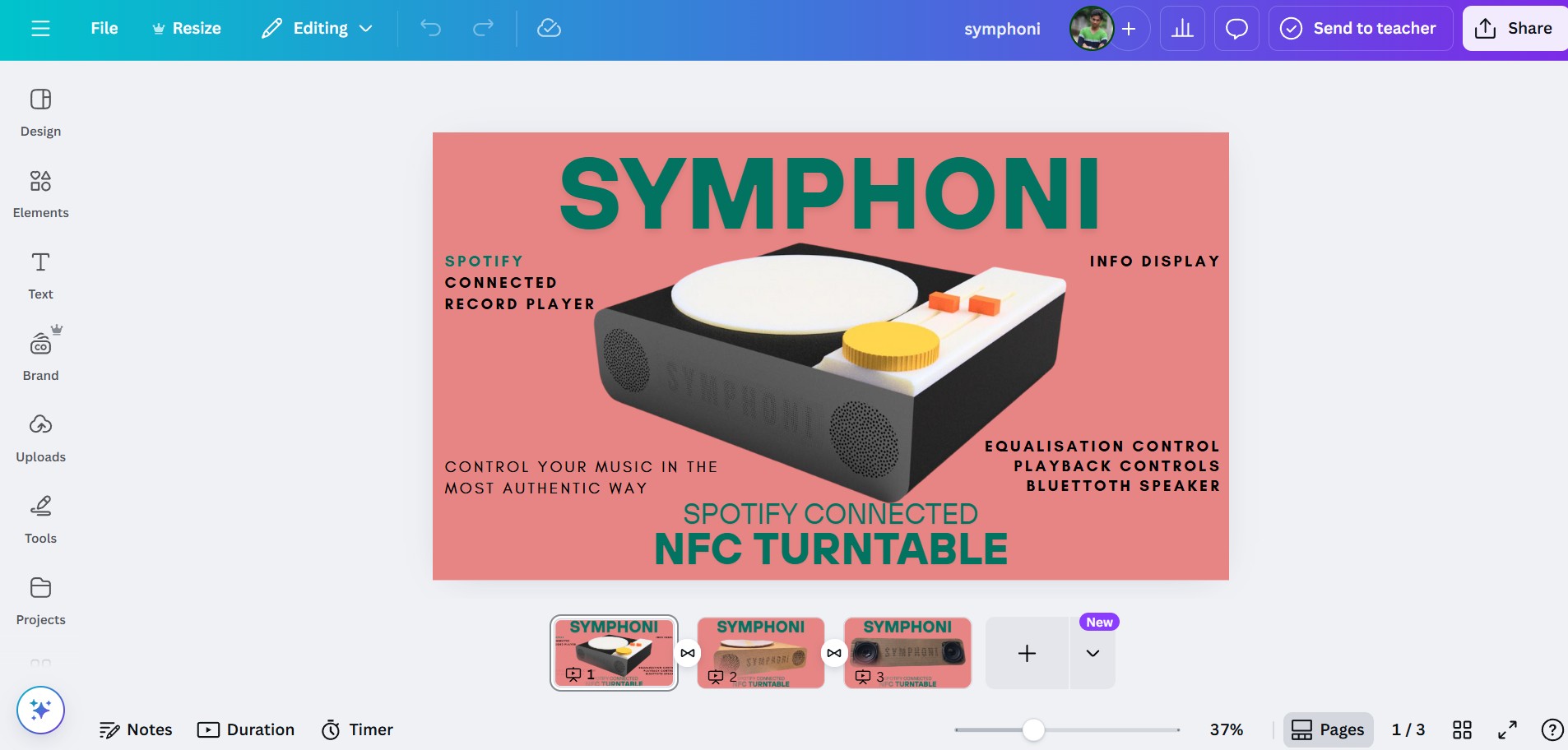
I used the Presentation Size preset to start designing my slide and Video. I added the rendered images to the slide and added some text about the features of the project.
For the video, I used the Canva Video preset to start designing my video. I added the rendered images to the video and added some text about the features of the project. The video is a short overview of the project, showcasing its key features and functionalities.
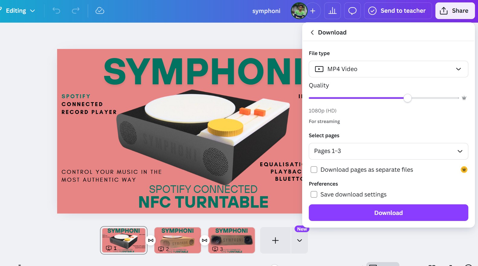
There are multiple options to export, I exported the three slides as a MP4 video of 1080p(HD) resolution.
The presentation slide(presentation.PNG) and video(presentation.mp4) are placed in the root directory of the repository.
Schedule
Week 1 (May 1 – May 7)
- CAD Design (Fusion 360):
- Design wooden enclosure for CNC routing
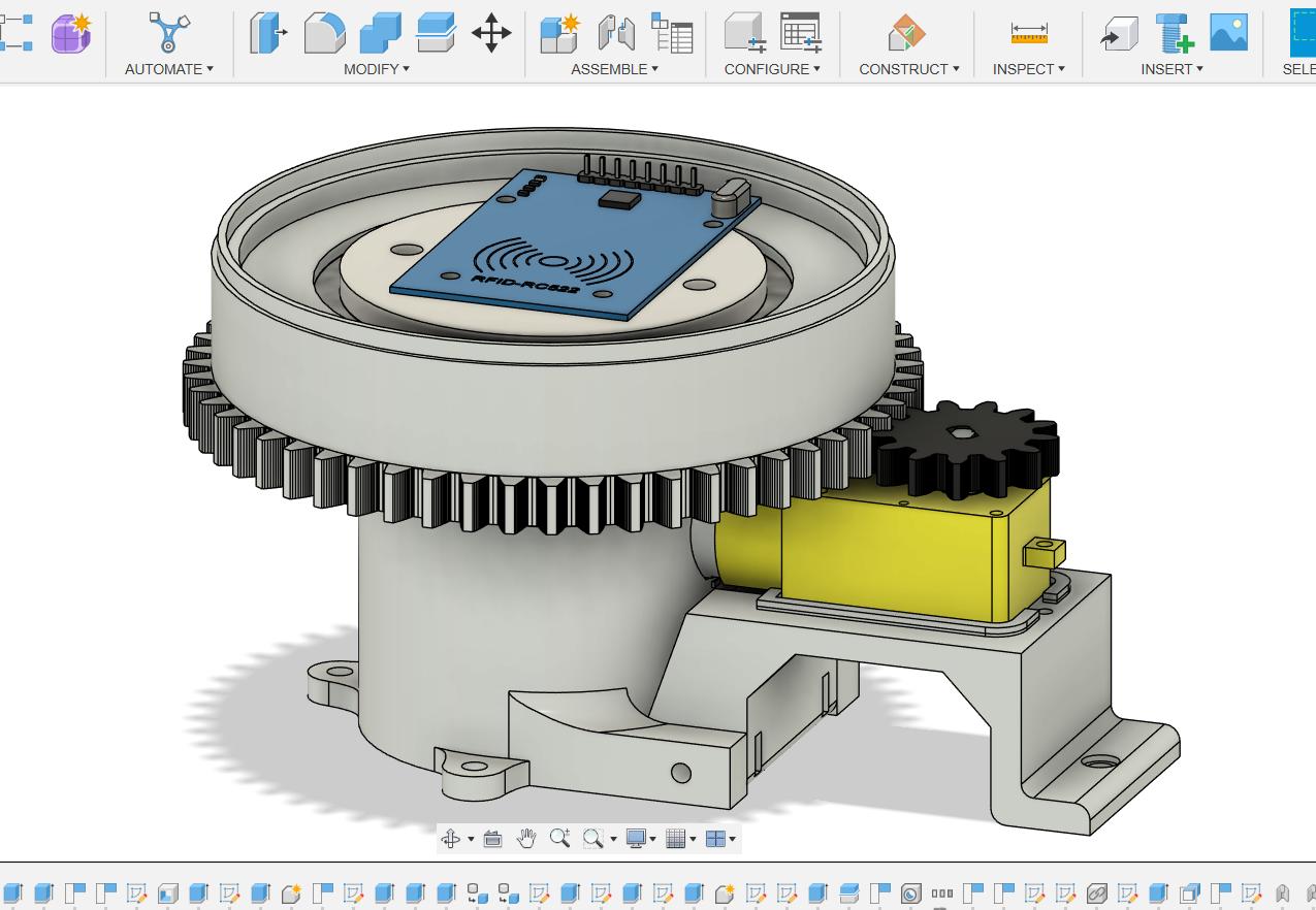
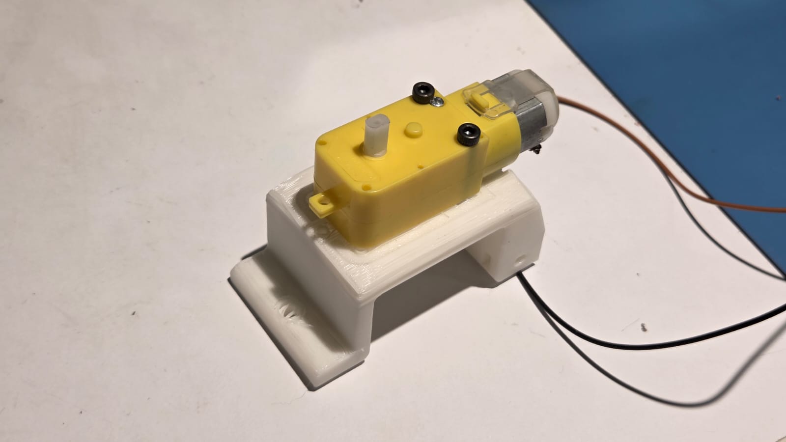
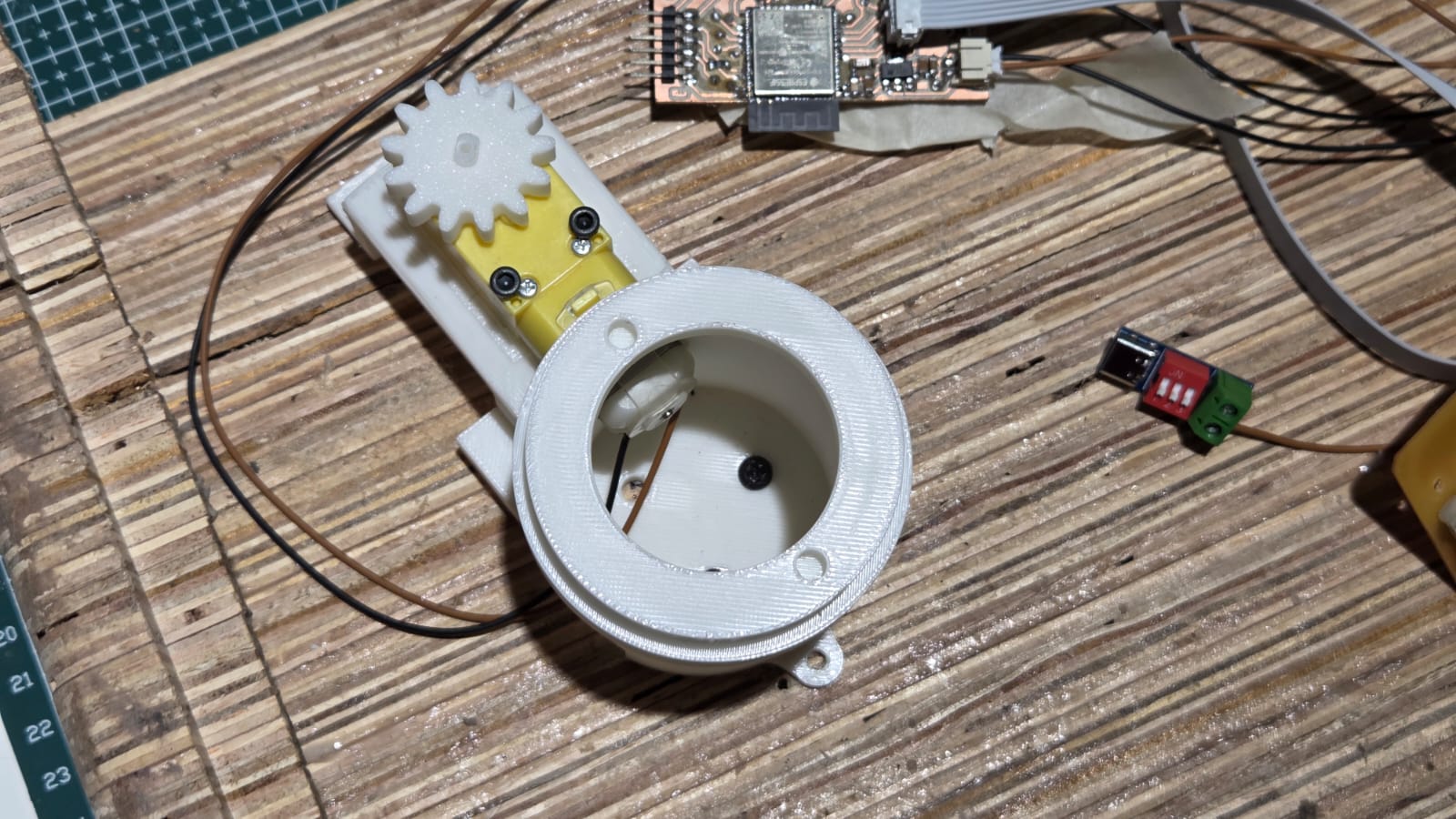
- Design motor mount & rotating platform
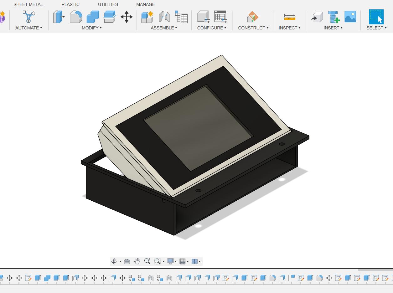
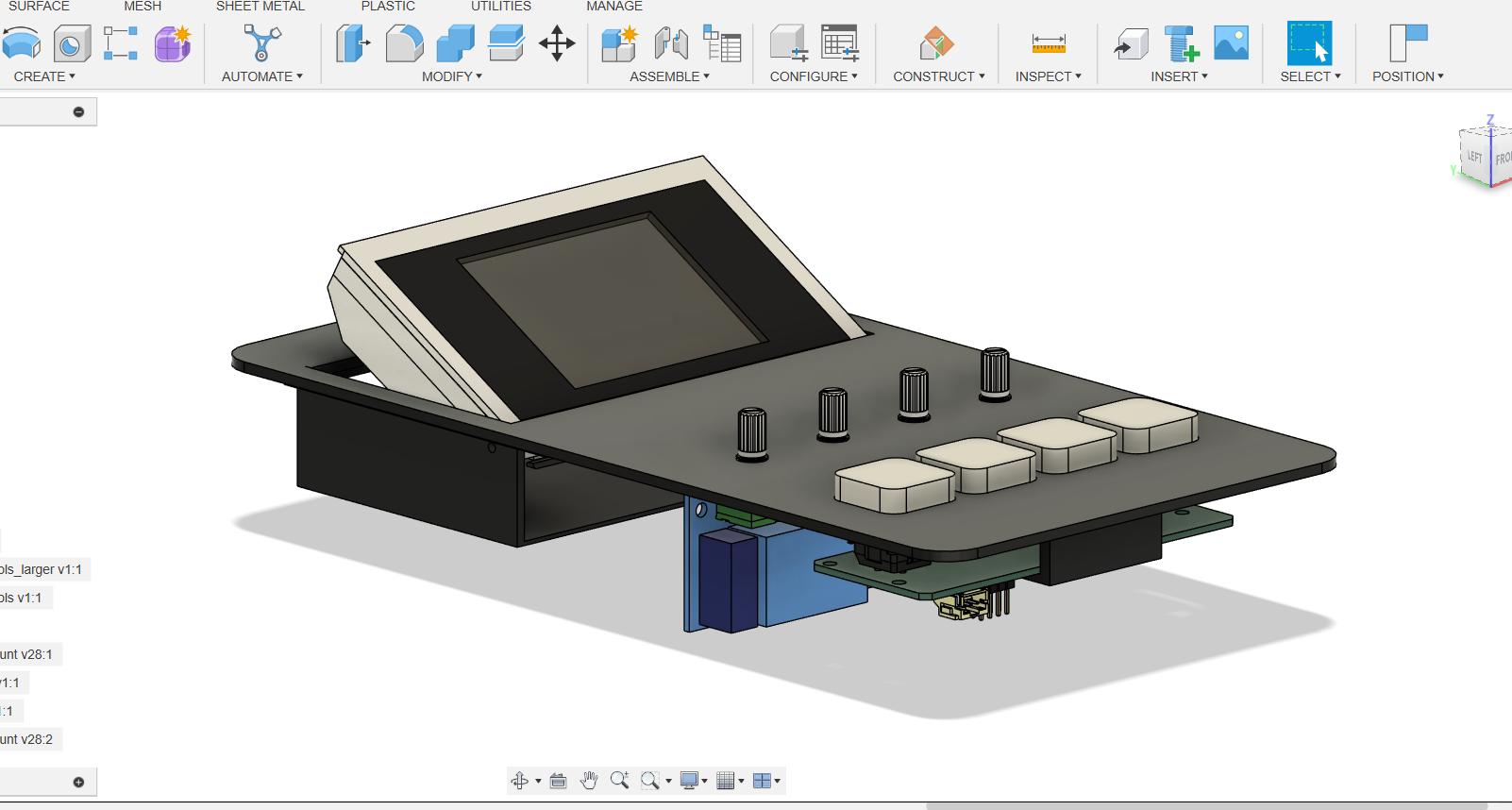
- Design display mount & button mounts
- PCB Design (KiCad):
- Main ESP32 Board (Spotify Connect)
- ESP32 Bluetooth Speaker PCB
- Power Management PCB
- Playback Control PCB with buttons
Week 2 (May 8 – May 14)
- PCB Production & Assembly:
- Fabricate the 4 PCBs
- Solder and assemble components
- Initial electrical validation for each board
- Mechanical Fabrication:
- CNC routing of wooden enclosure
- 3D printing of motor mounts, buttons & small parts
Week 3 (May 15 – May 21)
- Assembly:
- Assemble enclosure, motor mount, rotating platform, display & buttons
- Install and wire all PCBs (Main ESP32, Bluetooth Speaker, Power Mgmt, Playback Control)
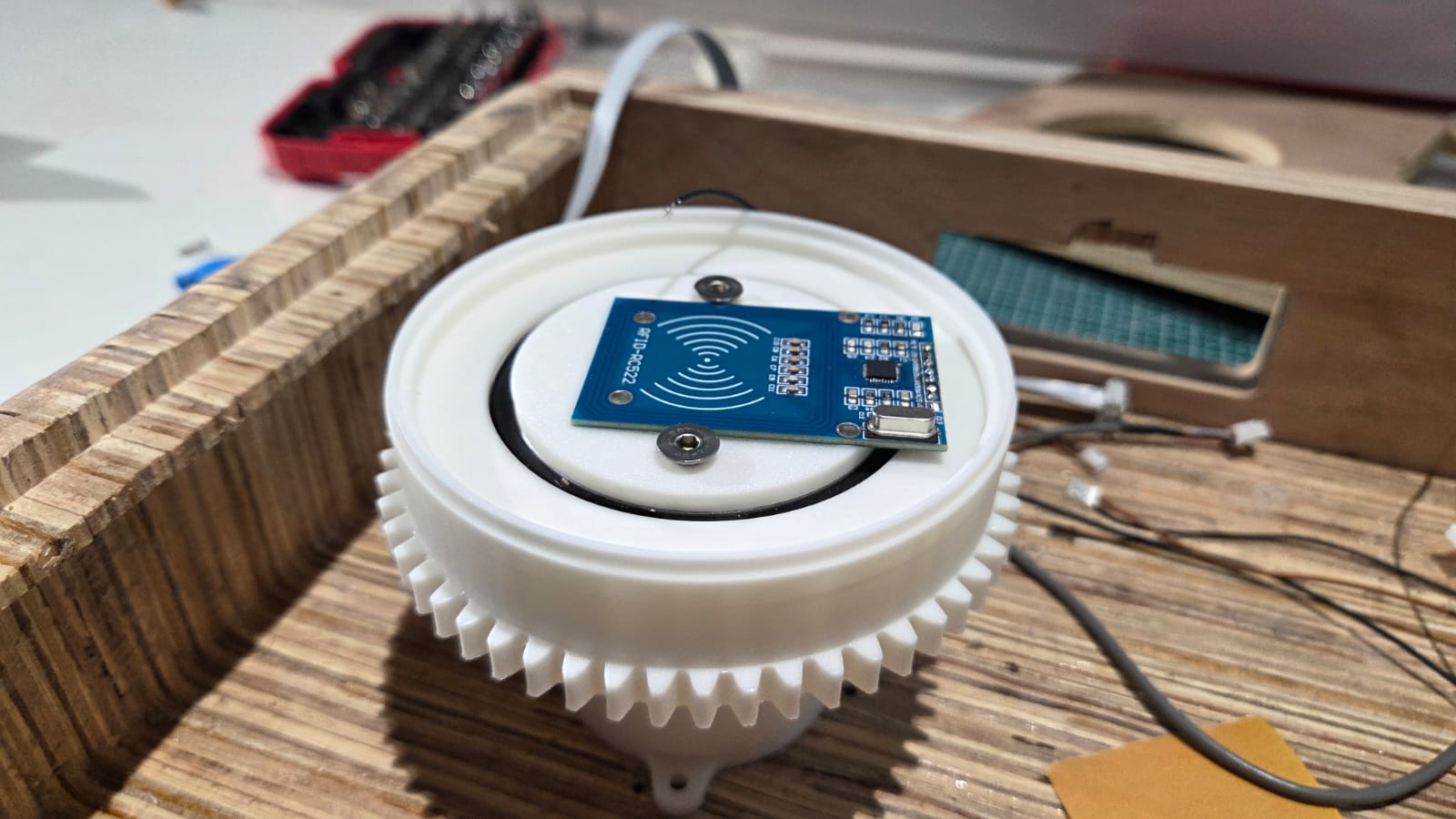
- Integrate motor, NFC reader and display inside enclosure
- Programming – Phase 1:
- Implement Spotify API communication
- Program NFC tag reading & writing
Week 4 (May 22 – May 28)
- Programming – Phase 2:
- Flutter app (UI + communication with ESP32)
- Display programming (album art, track info, etc.)
- Playback Control PCB: implement play/pause, next/prev, volume
- System Integration:
- Debug interaction between Spotify API, NFC, display, audio & controls
Week 5 (May 29 – June 4)
- Testing & Debugging:
- Full system integration tests
- Stress-test playback controls and NFC while record spins
- Optimize Bluetooth audio/streaming stability
- Capture working demo videos & photos
- Polish:
- Finish/paint wooden enclosure and apply aesthetic touches
Week 6 (June 5 – June 7) – Finalization
- Documentation & Submission:
- Write detailed Fab Academy documentation
- Organize and include CAD files, PCB files, firmware, and app code
- Prepare final slide deck and record/edit final project video
- Upload all documentation before June 7 deadline
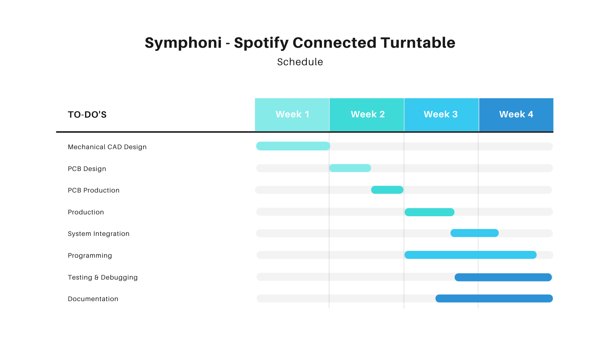
Gannt Chart
The Gannt Chart shows the approxiamte time required to complete the project. I have to dedicate more of the time on the physical design of th eenclosure and the integration of the components in the project. The programming of the project is also time intensive process as the programming and debugging process is
Schematic Design
I designed the schematic for my final project, Symphoni, using KiCad. The schematic includes an ESP32 for Wi-Fi and Bluetooth connectivity, a 2.8-inch SPI TFT display for visual output, NFC for NFC scanning.
I took this ESP32 Autoprogrammer circuit as a reference for my schematic design from my classmate Revisankar. The circuit is designed to program the ESP32 using a USB-to-serial converter, which allows for easy programming and debugging of the ESP32 module. The circuit includes necessary components such as resistors, capacitors, and a voltage regulator to ensure stable operation during programming.
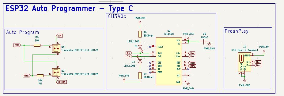
Realising that the Type C Auto Programmer would require a complex PCB Design, I chose to avoid the Type C part of it. I focused on the Auto programmer Circuit with the FTDI Programmer
Main Board Schematic
The main board is also based on the ESP32, which is a powerful microcontroller with built-in Wi-Fi and Bluetooth capabilities. The schematic includes components such as a 2.8-inch SPI TFT display for visual output, an NFC module for NFC scanning, and various passive components for signal conditioning and power management.
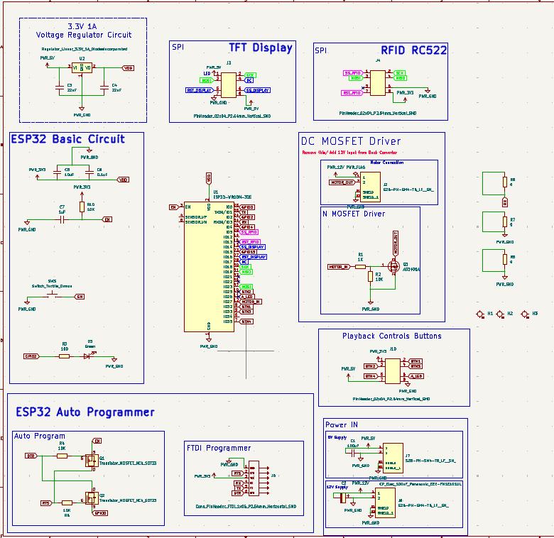
The above schematic is for the Symphoni Main Board it includes various componets which are explained in detailed in the below section.
ESP32 Pinout Reference - Random Nerd TutorialsThe above documentation by Random Nerd Tutorials talks about ESP32 Pinout Referenece: Which GPIO pins should you use?. It is very helpful for designing circuit boards with ESP32 WROOM modules.
This is the pinout provided in the above linked documentation. I kept these pins in mind while designing my schematic for the board.
| GPIO | Input | Output | Notes |
|---|---|---|---|
| 0 | pulled up | OK | outputs PWM signal at boot, must be LOW to enter flashing mode |
| 1 | TX pin | OK | debug output at boot |
| 2 | OK | OK | connected to on-board LED, must be left floating or LOW to enter flashing mode |
| 3 | OK | RX pin | HIGH at boot |
| 4 | OK | OK | |
| 5 | OK | OK | outputs PWM signal at boot, strapping pin |
| 6 | ✘ | ✘ | connected to the integrated SPI flash |
| 7 | ✘ | ✘ | connected to the integrated SPI flash |
| 8 | ✘ | ✘ | connected to the integrated SPI flash |
| 9 | ✘ | ✘ | connected to the integrated SPI flash |
| 10 | ✘ | ✘ | connected to the integrated SPI flash |
| 11 | ✘ | ✘ | connected to the integrated SPI flash |
| 12 | OK | OK | boot fails if pulled high, strapping pin |
| 13 | OK | OK | |
| 14 | OK | OK | outputs PWM signal at boot |
| 15 | OK | OK | outputs PWM signal at boot, strapping pin |
| 16 | OK | OK | |
| 17 | OK | OK | |
| 18 | OK | OK | |
| 19 | OK | OK | |
| 20 | OK | OK | |
| 21 | OK | OK | |
| 22 | OK | OK | |
| 23 | OK | OK | |
| 24 | OK | OK | |
| 25 | OK | OK | |
| 26 | OK | OK | |
| 27 | OK | OK | |
| 32 | OK | OK | |
| 33 | OK | OK | |
| 34 | input only | ✘ | |
| 35 | input only | ✘ | |
| 36 | input only | ✘ | |
| 39 | input only | ✘ |
Components in Schematic
There are various types of components and circuits in the Schematic Design.
ESP32 Auto Programmer with FTDI PinoutThe ESP32 requires a boot and reset button while programming, which needs to be held while programming for successful uploading the program. To avoid the hassle of using the buttons, we can use the auto programmer circuit which consists of N Channel Mosfets. The GPIO 0 and EN pins are used for this.
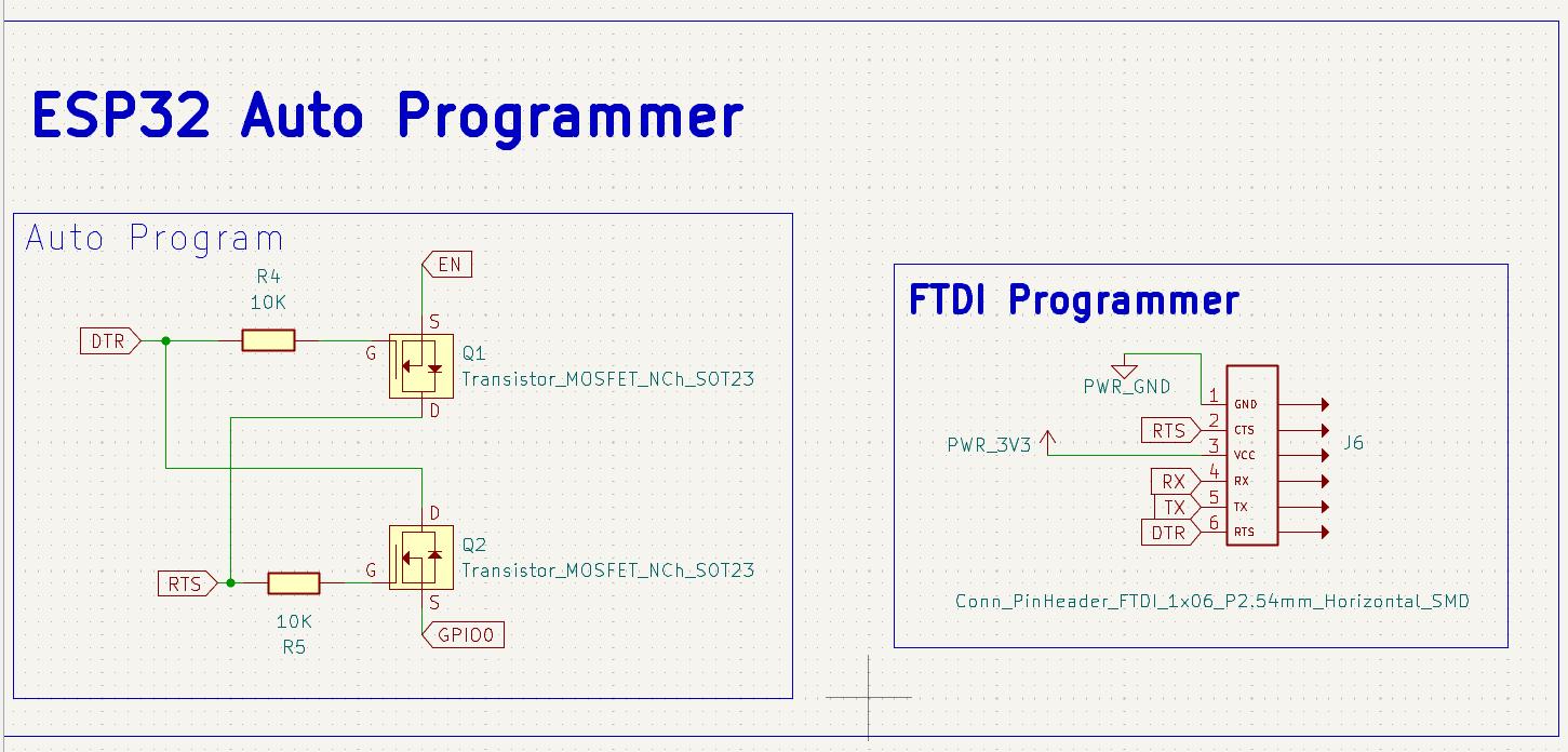
To program the board I'll be using a FTDI Programmer, that's why I kept the FTDI Pins using a 6 Pin Horizontal SMD.
ESP32 Basic CircuitThe ESP32 requires the below given minium circuit for basic operation. Initially I didn't notice this circuit and had to manually make these connections in my board. This is the minimum circuit for proper booting and programming for ESP32.
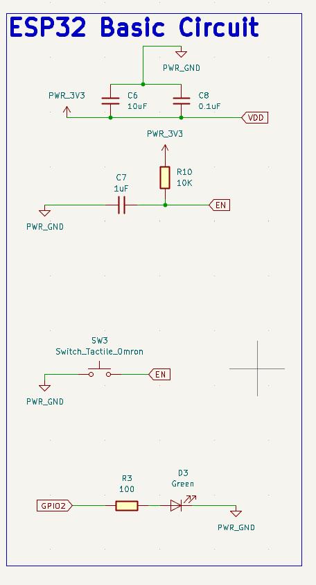
The ESP32 chip has the following strapping pins:
- GPIO 0 (must be LOW to enter boot mode)
- GPIO 2 (must be floating or LOW during boot)
- GPIO 4
- GPIO 5 (must be HIGH during boot)
- GPIO 12 (must be LOW during boot)
- GPIO 15 (must be HIGH during boot)
Enable (EN) is the 3.3V regulator's enable pin. It's pulled up, so connect to ground to disable the 3.3V regulator. This means that you can use this pin connected to a pushbutton to restart your ESP32, for example.
Voltage Regulator CircuitThe ESP32 WROOM Moduel runs on 3.3V, therefore to provide a regulated 3.3V Voltage Supply I used this Voltage Regulator Circuit. The Input for the Voltage regulator is the 5V Power input.
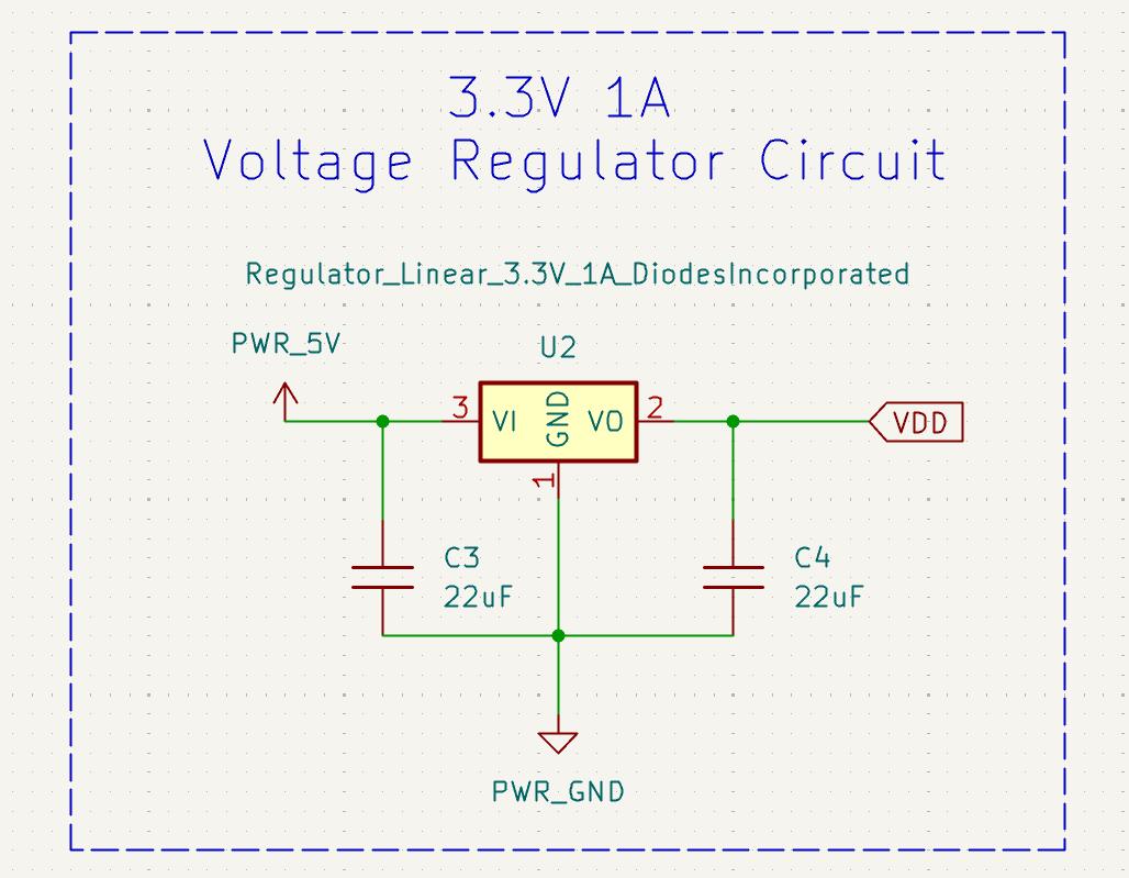
The board requires two sources of voltage input: 5V and 12V. The 5V is required to power the ESP32 through the voltage regualtor circuit. The 12V is required to drive the DC BO Motor which drives the turntable.
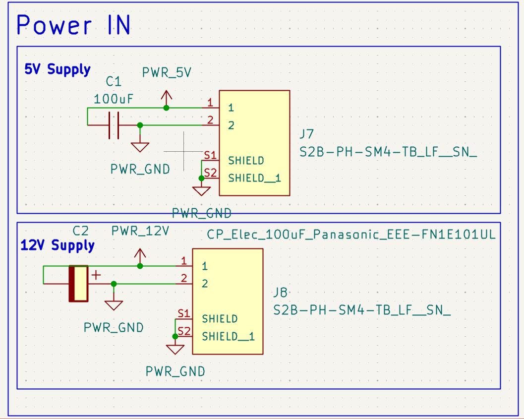
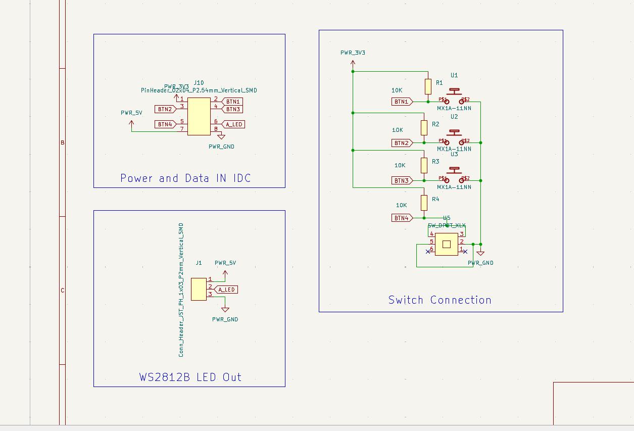
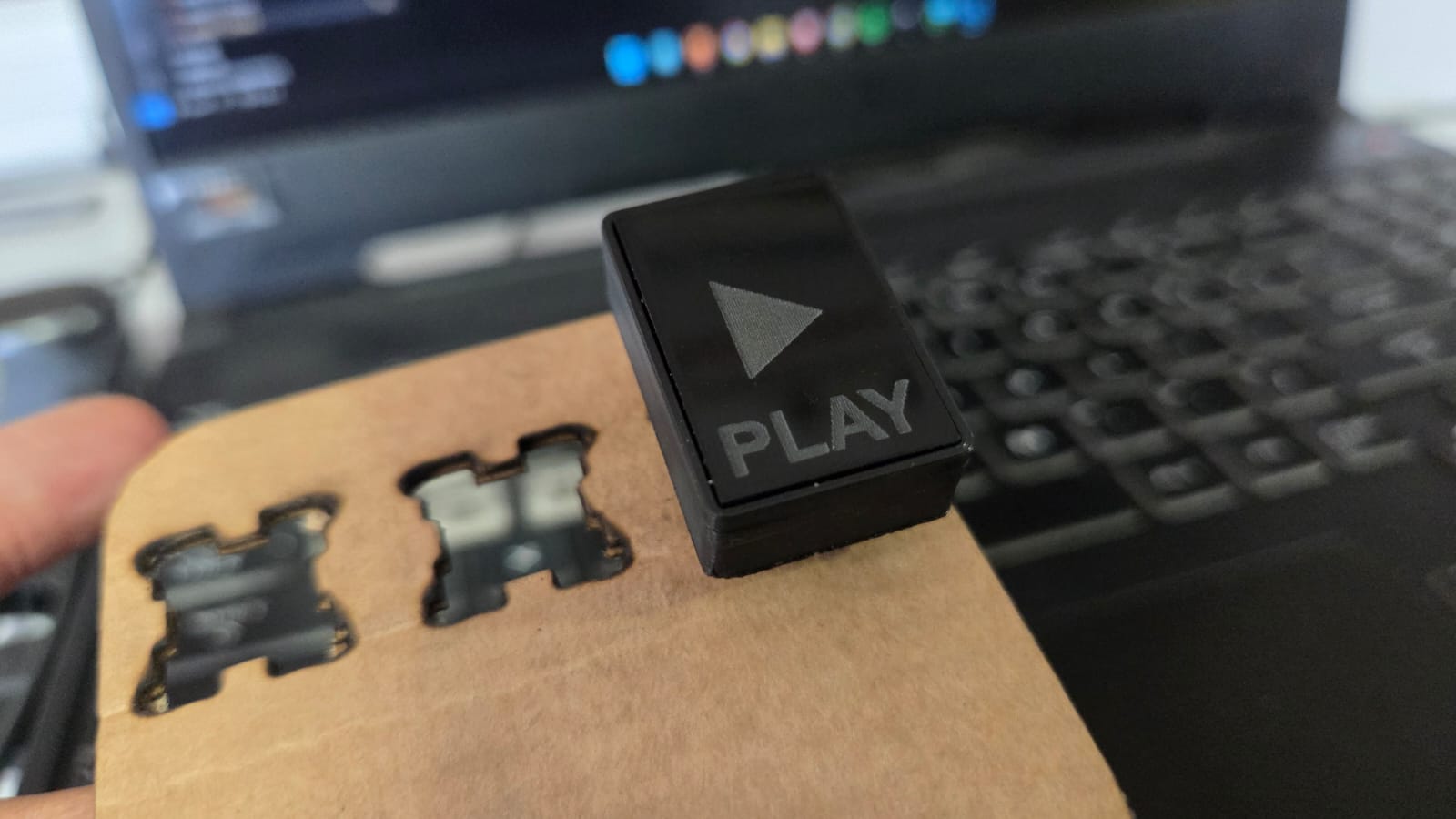
The power inputs are through a 1x2 JST Connectors
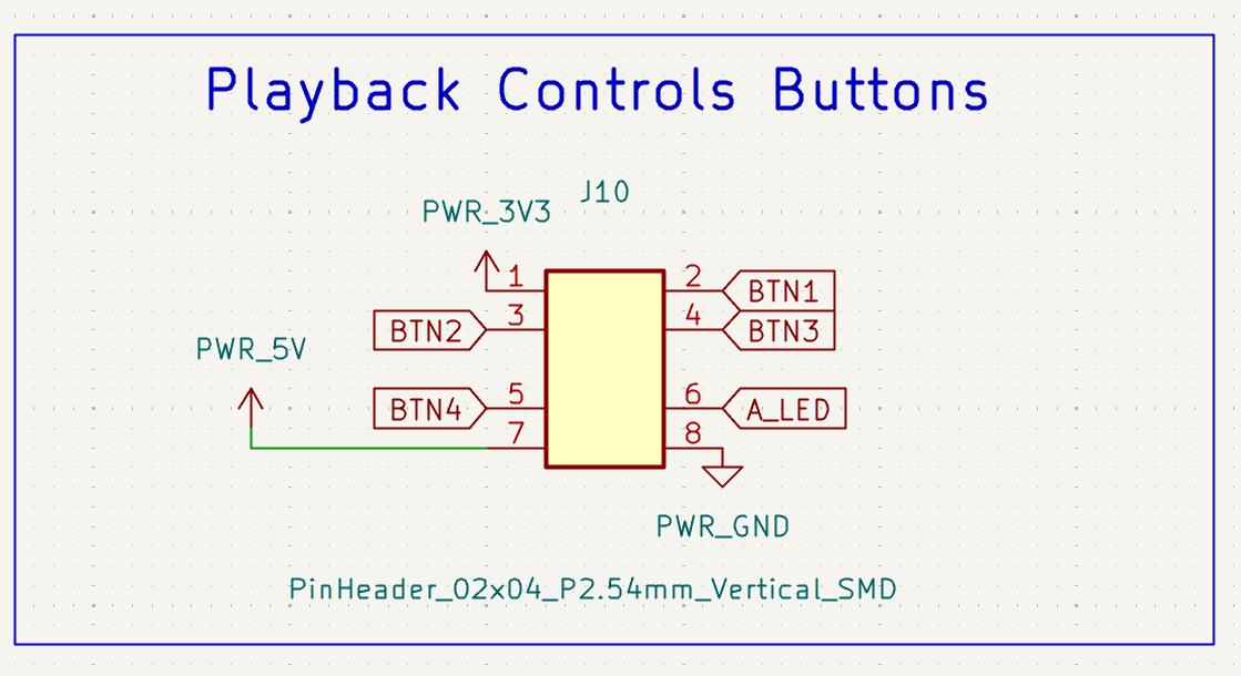
Playback Control PinsThe playback controls for the record player are on a separate PCB which houses 3 Mechanical Switches and one self Latching Switch. To connect the main board to the Playback Controls PCB, i'll be using the 8 Pin IDC Connector: 4 Pins for Switches, 3.3V, and GND. The additional 2 pins are for controlling a addressable LED(Data IN) and 5V for the LEDs. That's why I am using the 02x04 Vertical SMD Header for the same.
THe other two peripherals that will connected to this board are the SPI TFT Display and the MFRC522 RFID Reader Module, which are both using the SPI protocol. I have used the default ESP32 pins for MOSI, MISO and SCK and the Chip Select (CS) and reset (RST) pins are different for the two devices.
SPI
By default, the pin mapping for SPI is:
| SPI | MOSI | MISO | CLK | CS |
|---|---|---|---|---|
| VSPI | GPIO 23 | GPIO 19 | GPIO 18 | GPIO 5 |
| HSPI | GPIO 13 | GPIO 12 | GPIO 14 | GPIO 15 |
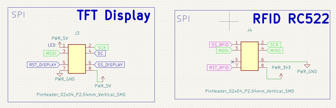
I'll be using the 2x4 SMD Header Pins to connect using the IDC Connectors to the Display and RFID Reader.
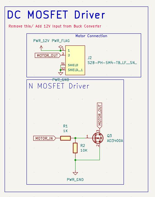
Motor MOSFET based DriverThe turntable is driven by a DC BO Motor which is controlled using a MOSFET based driver circuit. The MOSFET is controlled using the ESP32 GPIO pin and the motor is powered by the 12V power input.
The below schematic PDF is the final schematic design of the Symphoni PCB board.
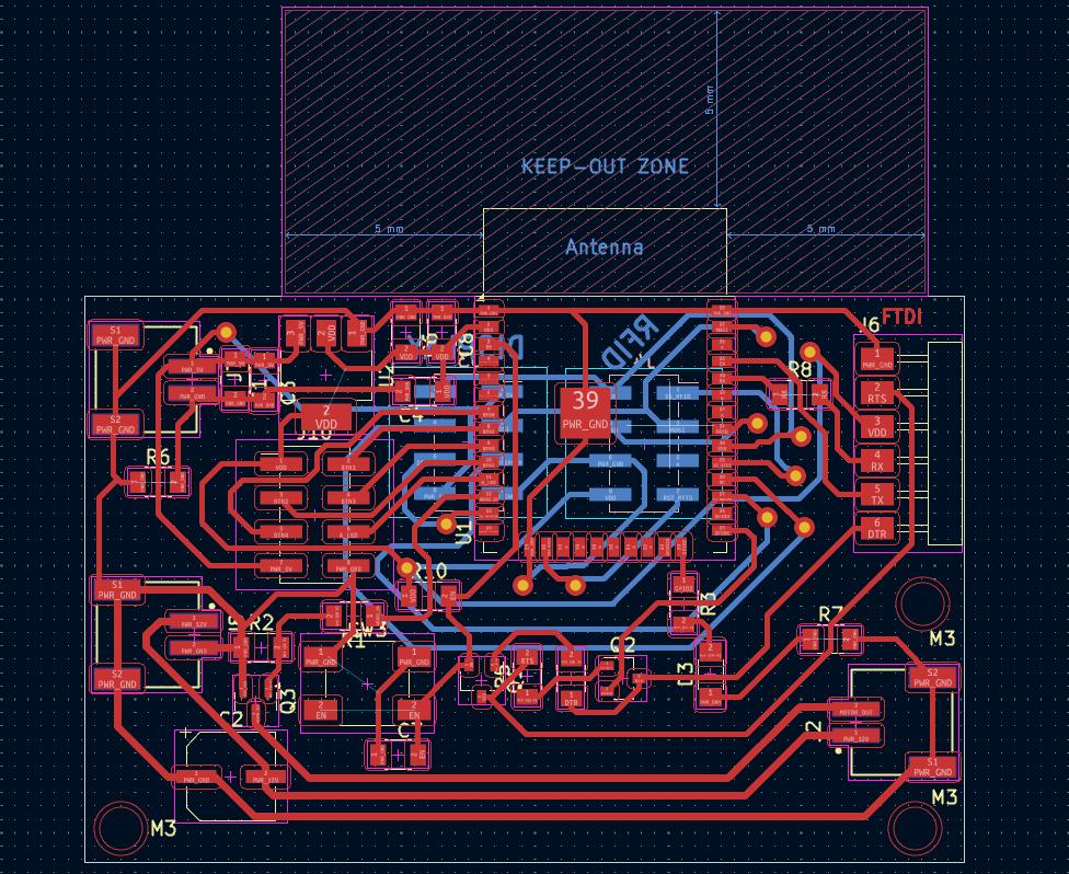
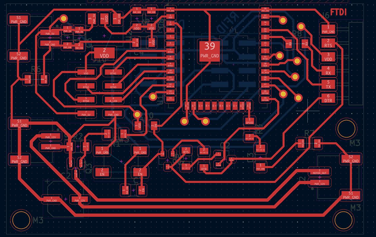
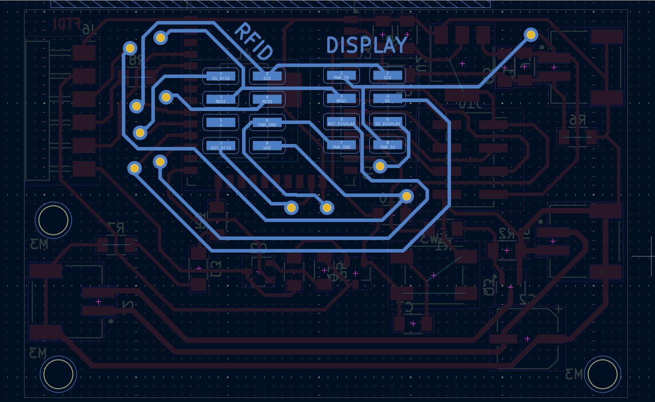
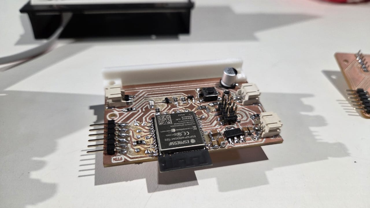
Symphoni Schematic PDFPCB Design
I designed a 2 side PCB for this as I had many peripheral conections like the RFID Reader, TFT Display, Motor, Buttons, etc. which were all further away from the mainboard.
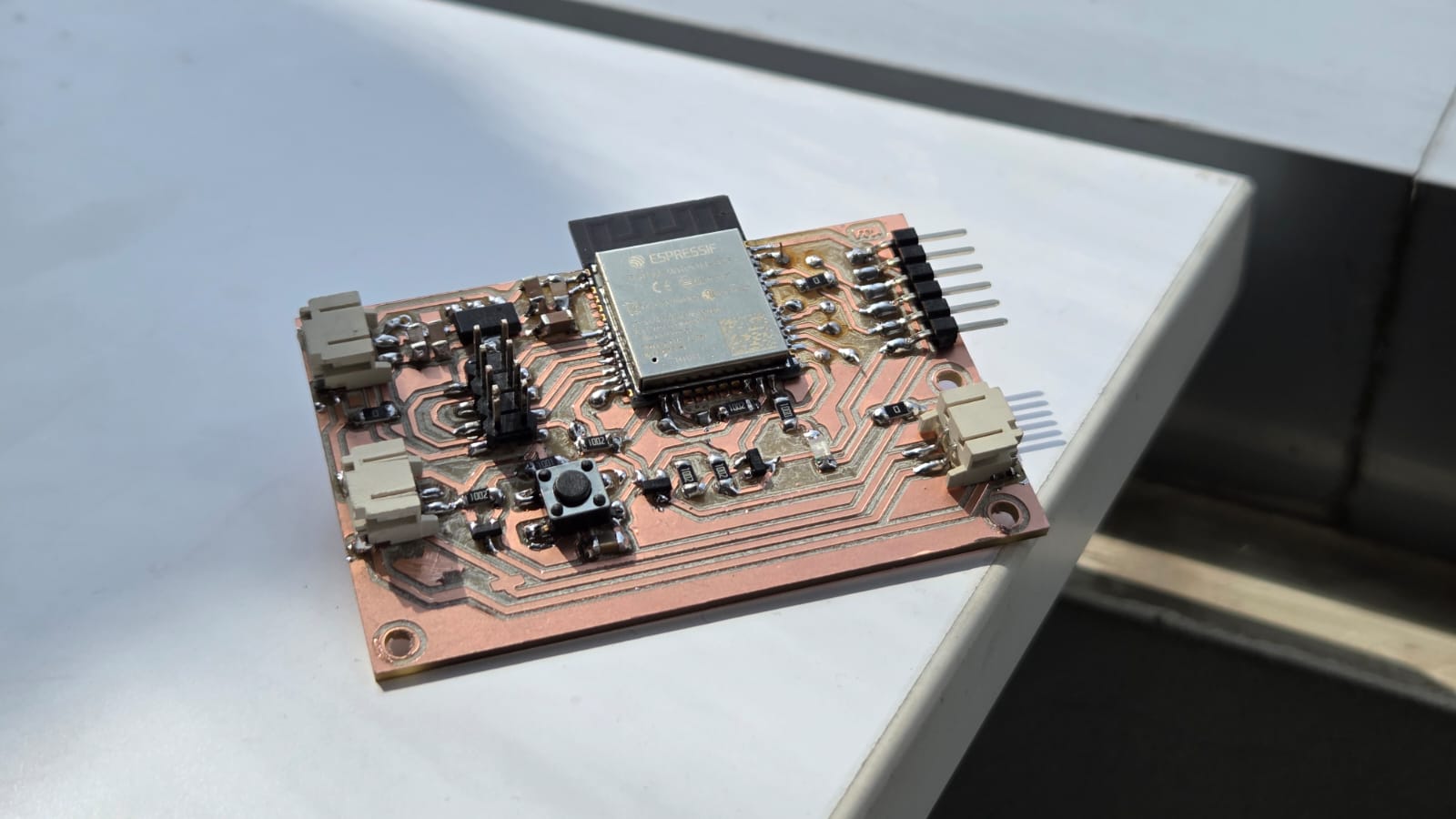
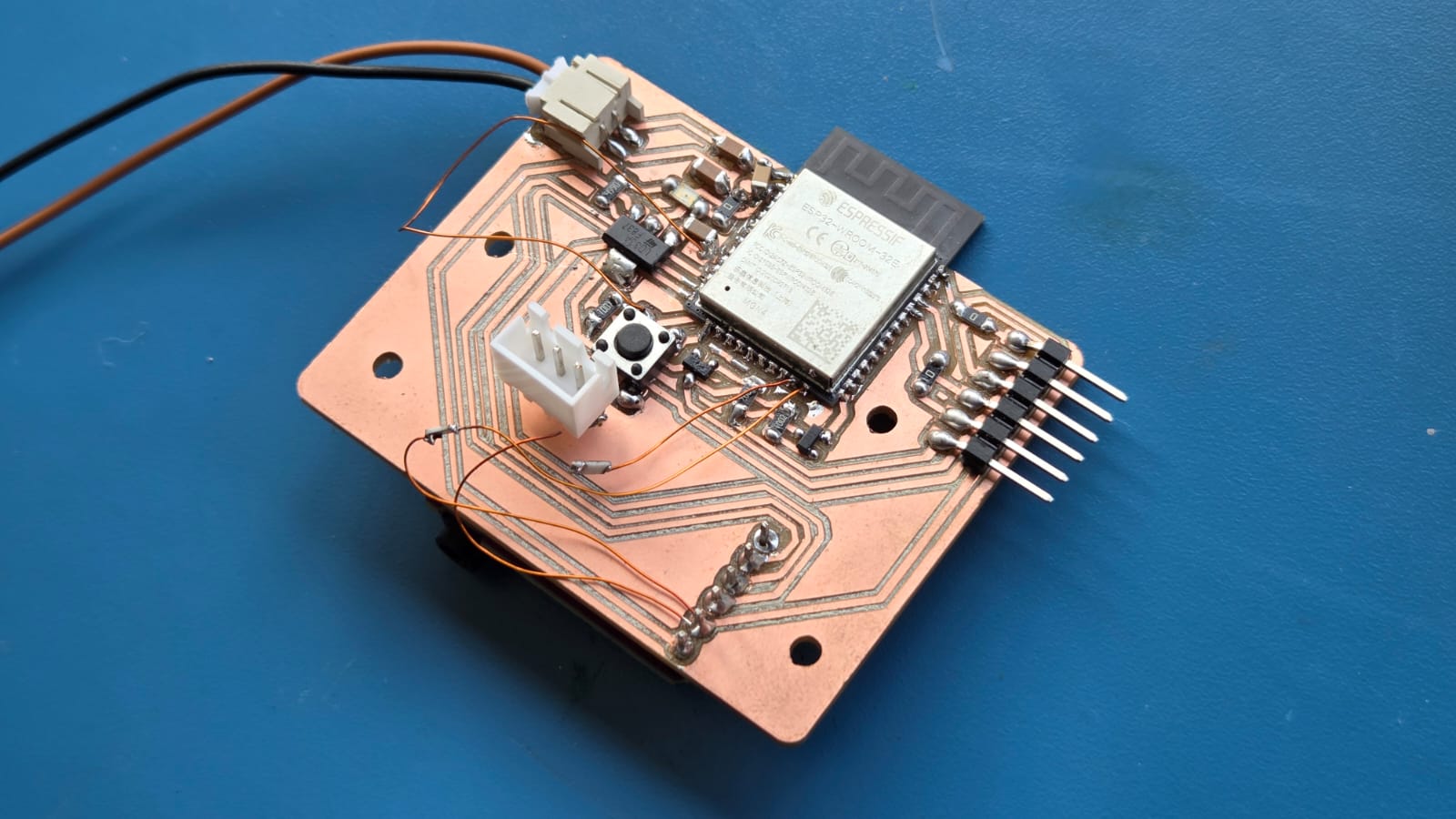
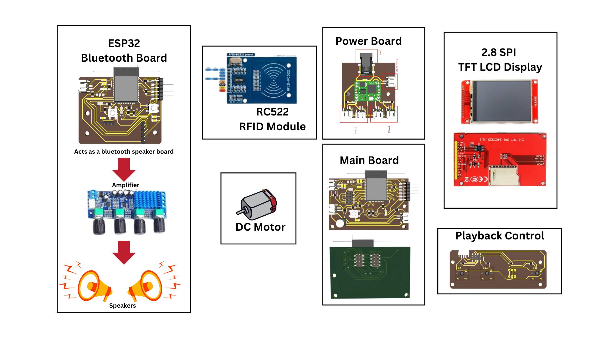
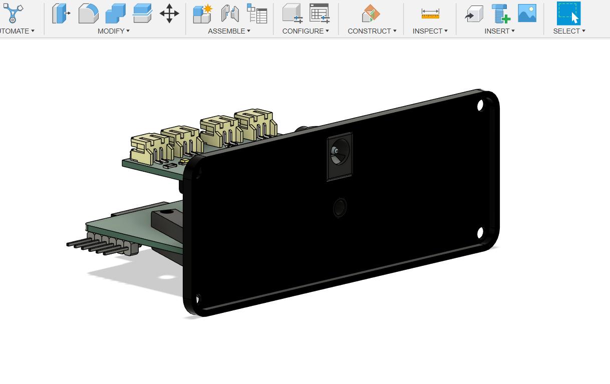
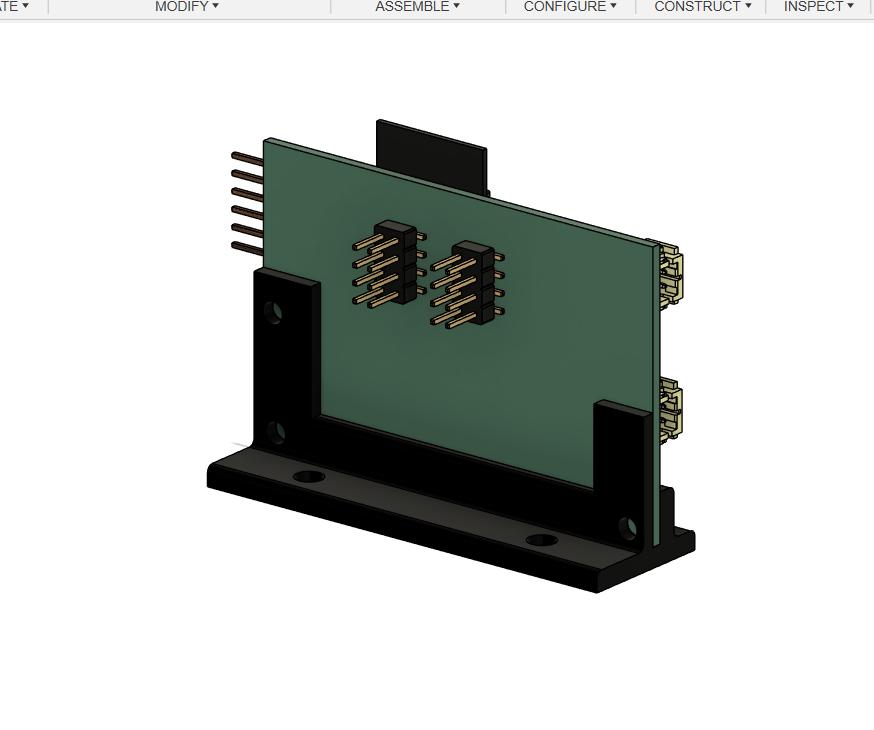
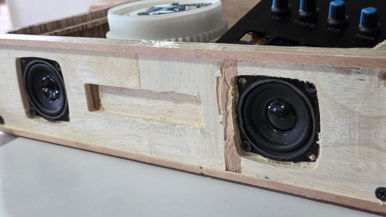
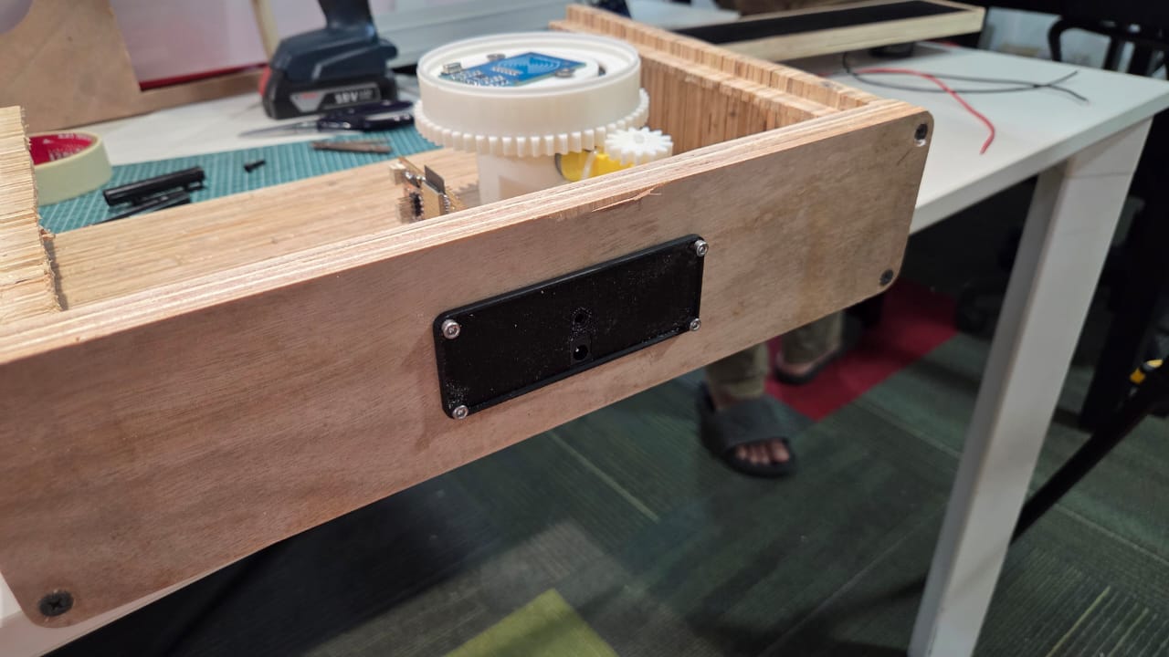
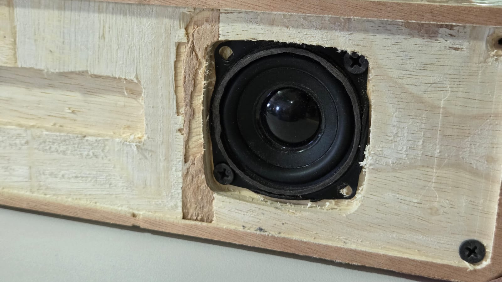
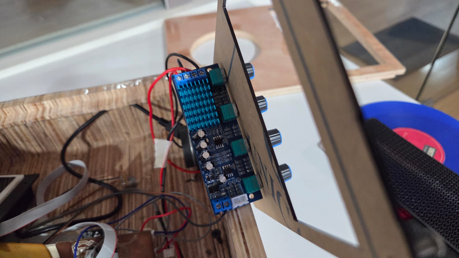
Symphoni - Bluetooth Speaker Module
The bluetooth module is a part of the Symphoni project, which is a Bluetooth speaker system that allows users to play music from their smartphones or other Bluetooth-enabled devices. The module is designed to be compact and efficient, providing high-quality audio output while being easy to integrate into various projects. The module uses an ESP32 microcontroller for Bluetooth connectivity and audio processing. I have used the TPA3116D2 amplifier for driving the speakers using a PCM5102 I2S DAC module connected to the ESP32. The PCB design includes the necessary components for power management, audio output, and Bluetooth communication. The module is designed to be compatible with various speaker drivers and can be easily integrated into my final project.

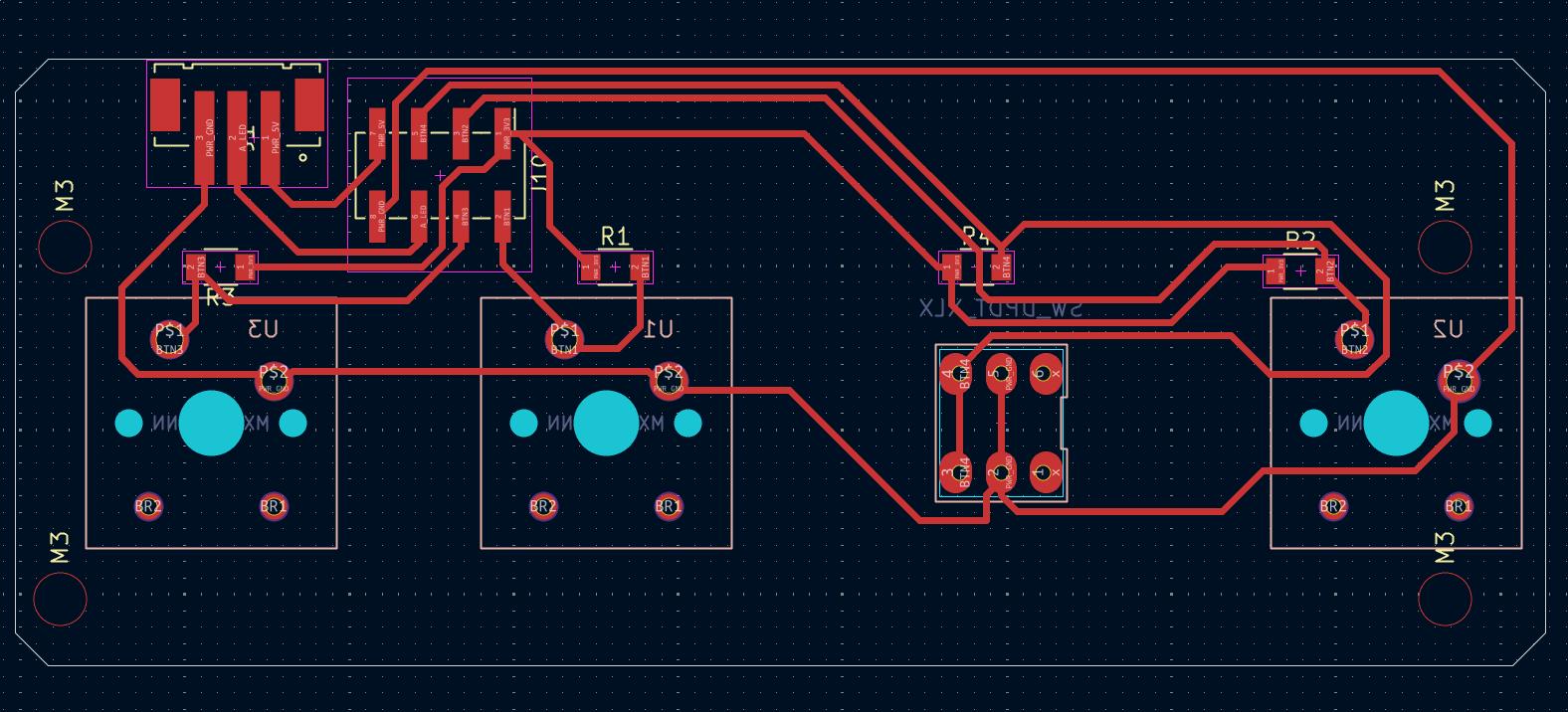
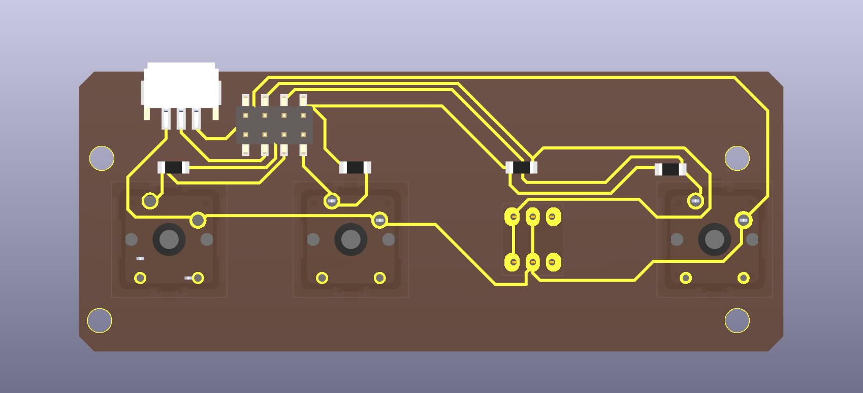
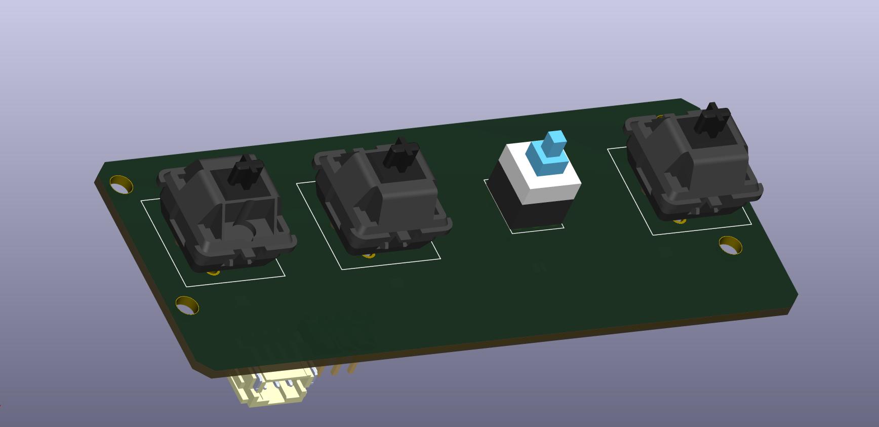
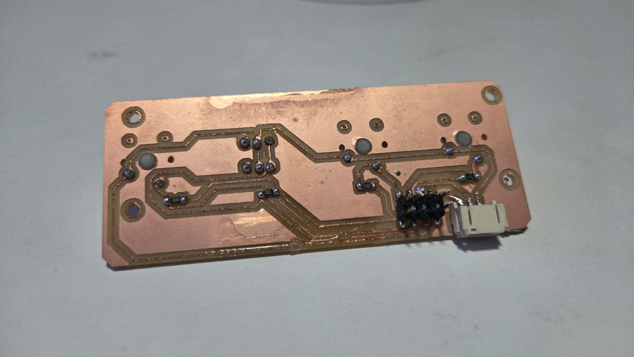
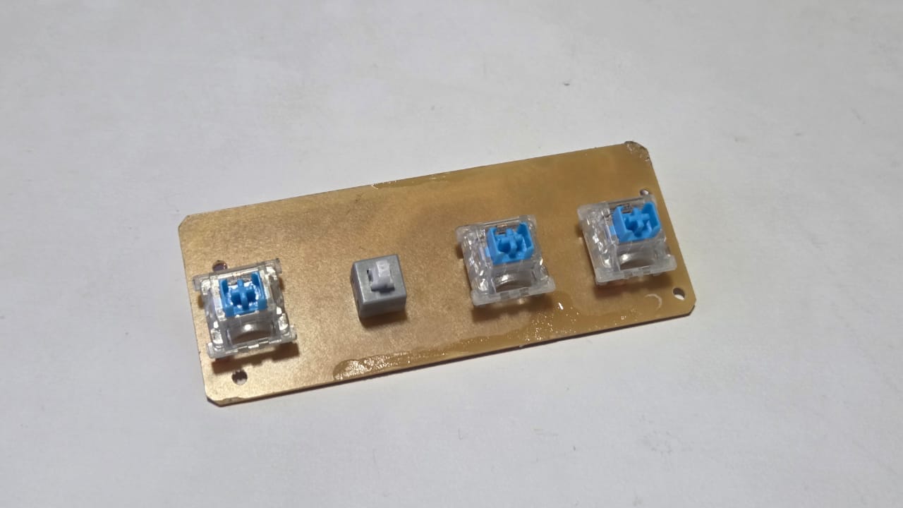
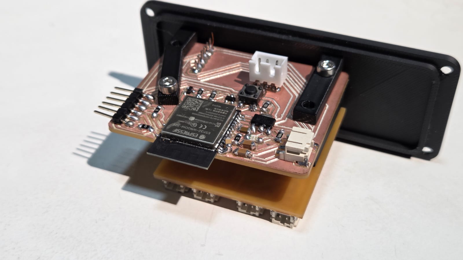
Playback Controls PCB
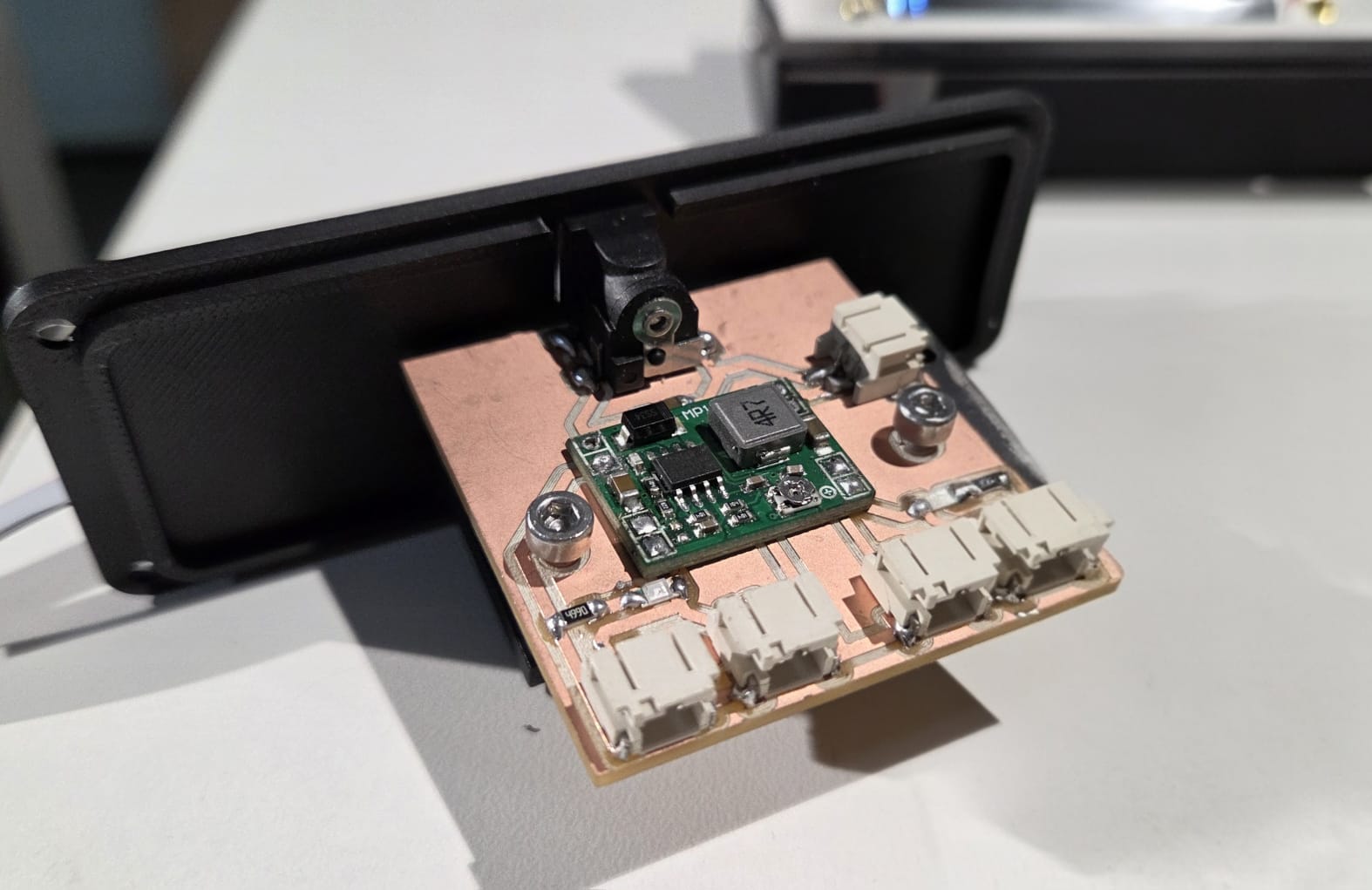
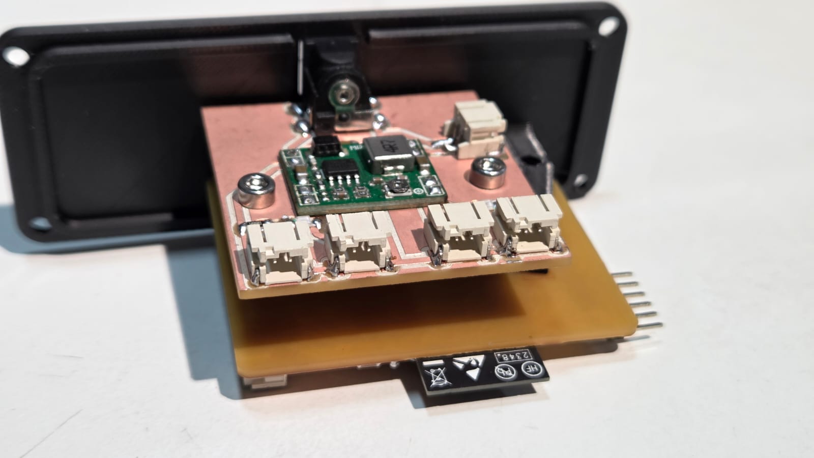
Power Board
MP1584 Kicad Files ZIP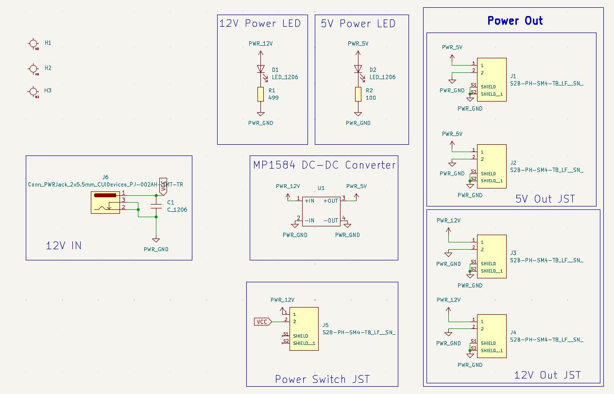
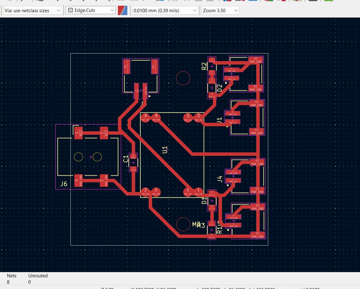
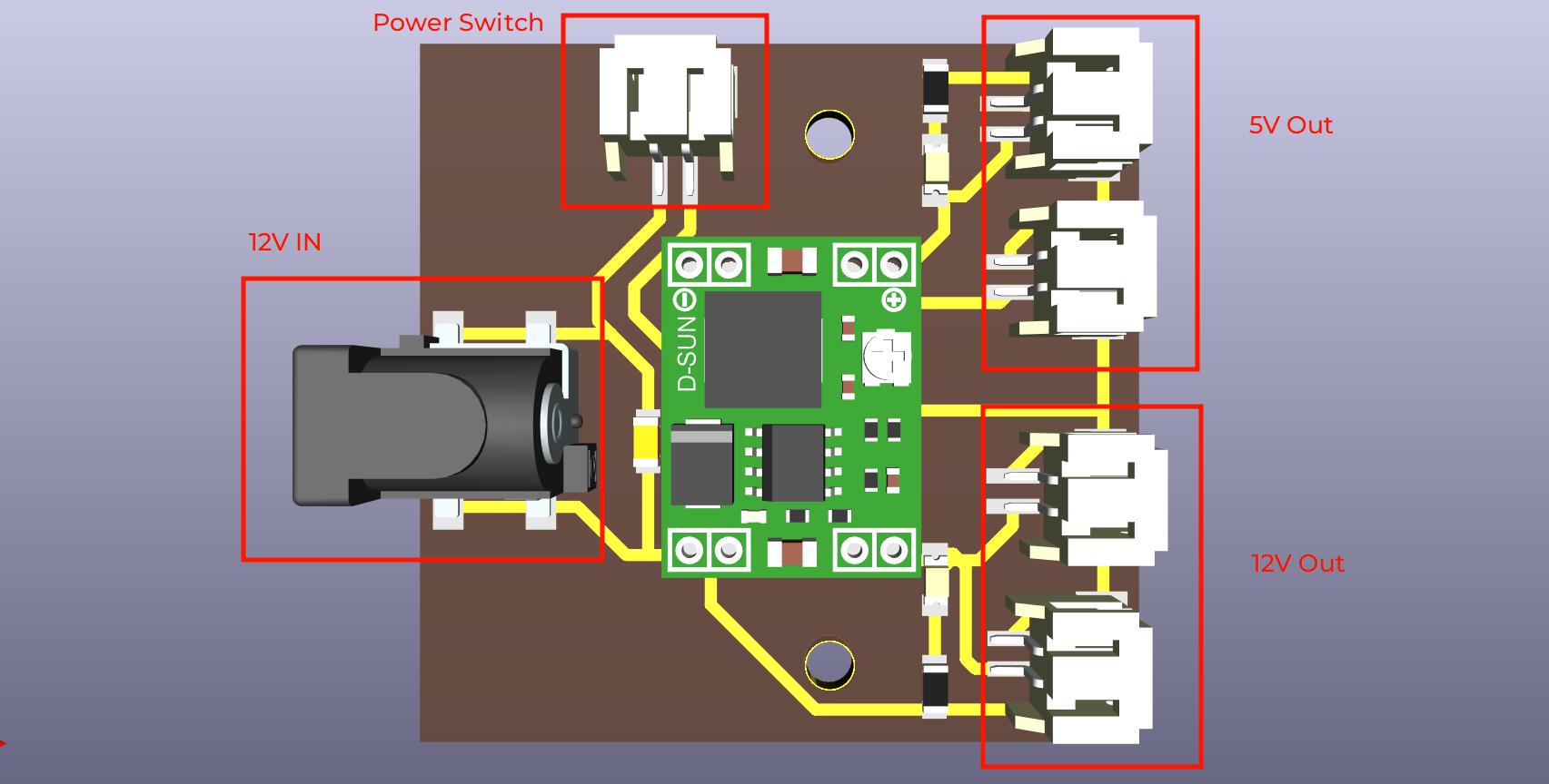
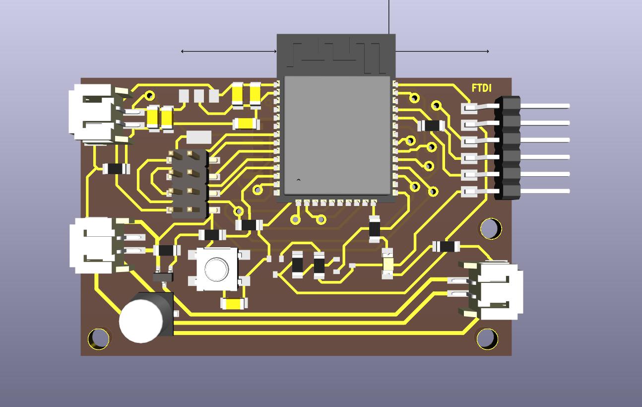
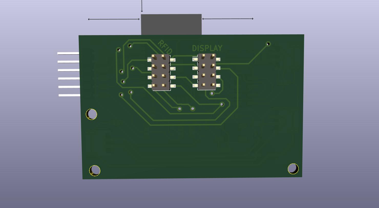
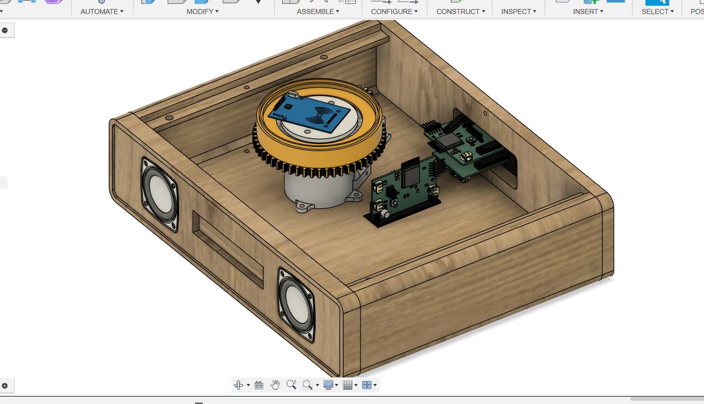
Electronics Layout
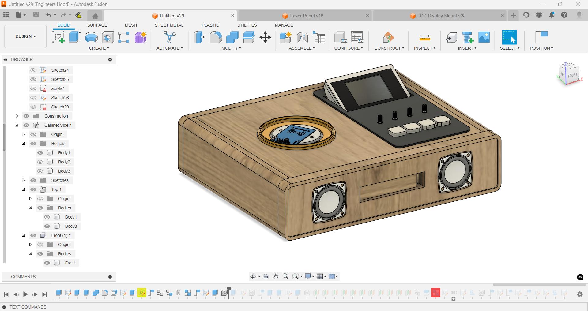
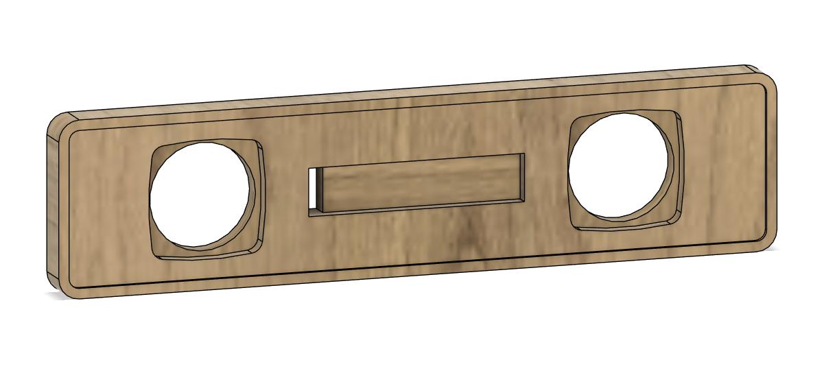
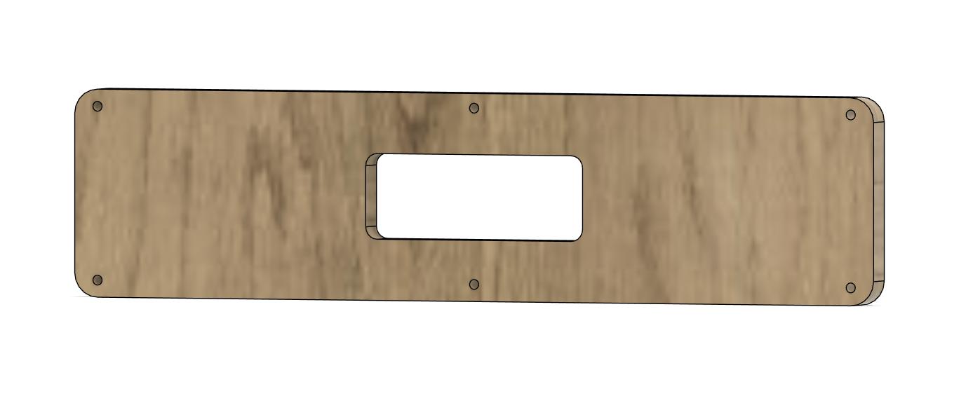
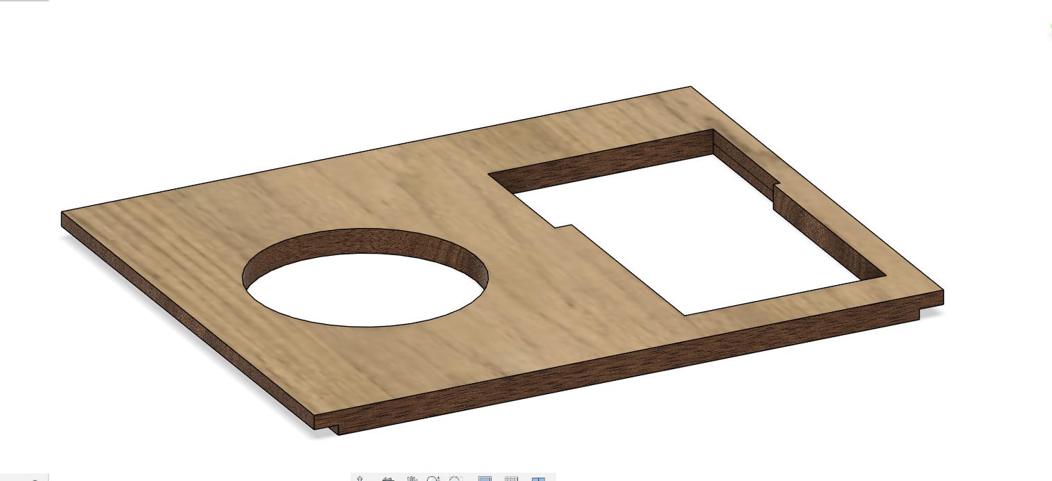
CAD Design
I used Fusio360 to design the enclosure for the project.
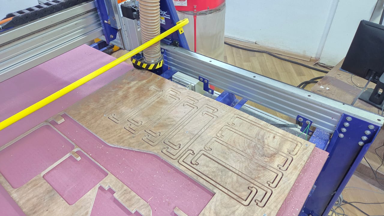
Production and Manufacturing
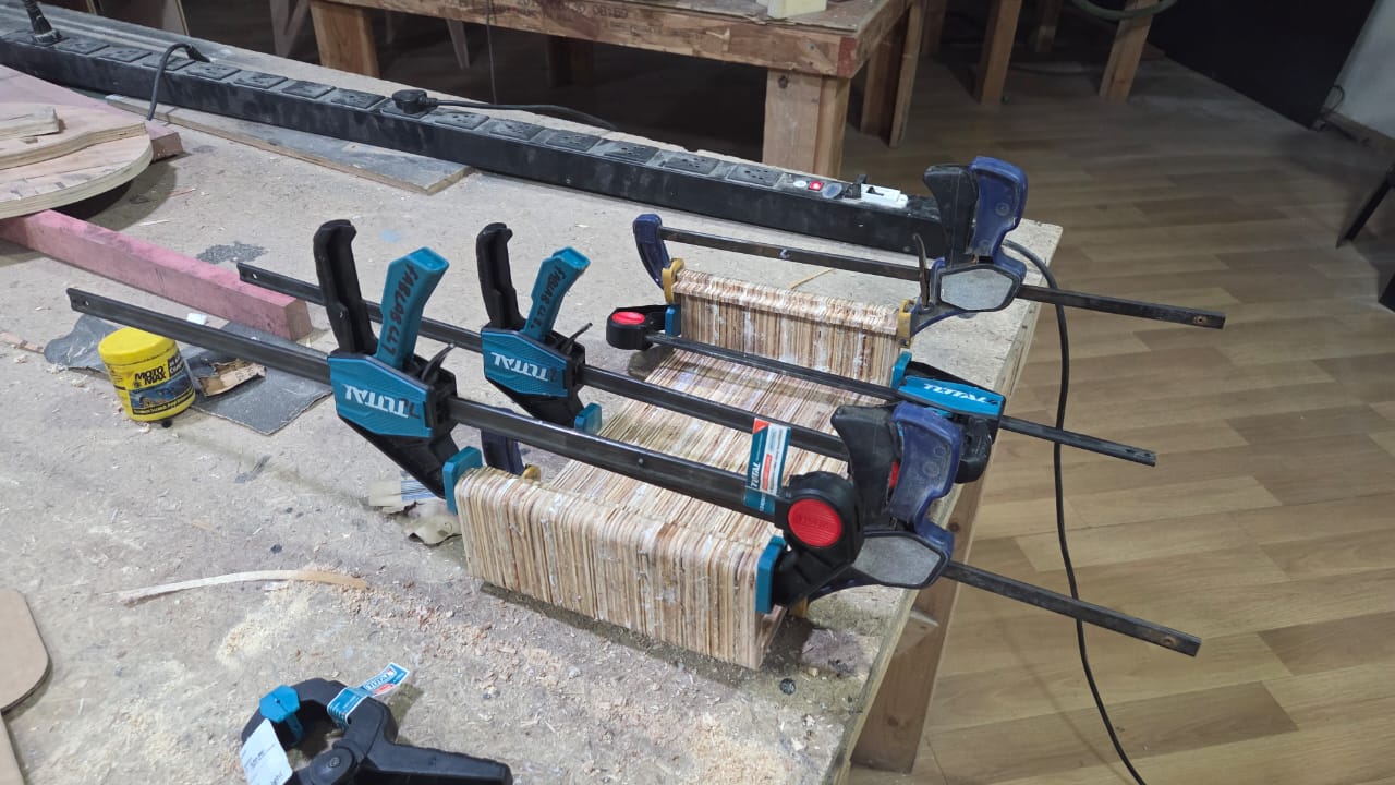
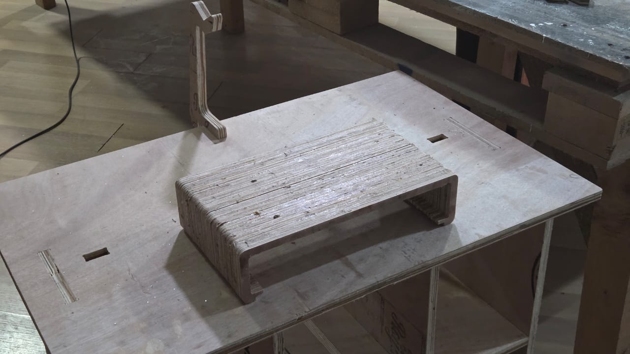
CNC Machining Plywood
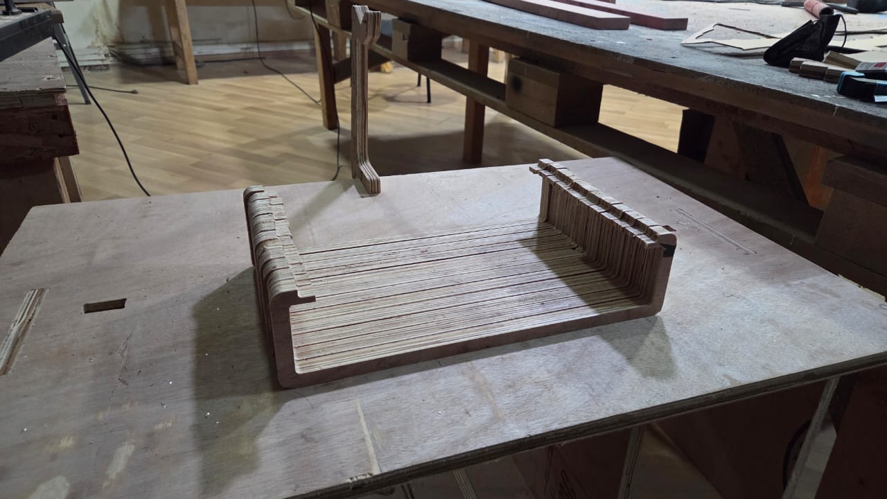
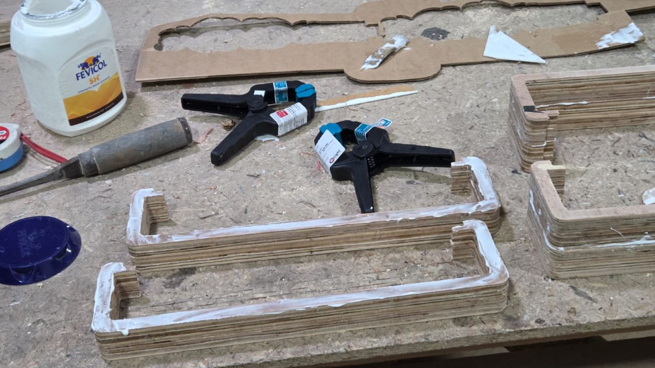
I used Fevicol Wood Adhesive to glue the cross-sections together and used clamps available at the lab. Initially I stuck pairs of two pieces with the help of Saheen and clamped them and left them for a few hours before releasing them from the clamps.
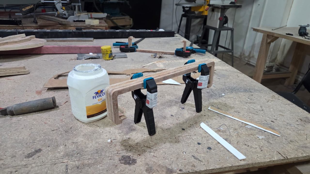
After that I stacked them together and clamped them again and left them for a few hours before releasing them from the clamps.
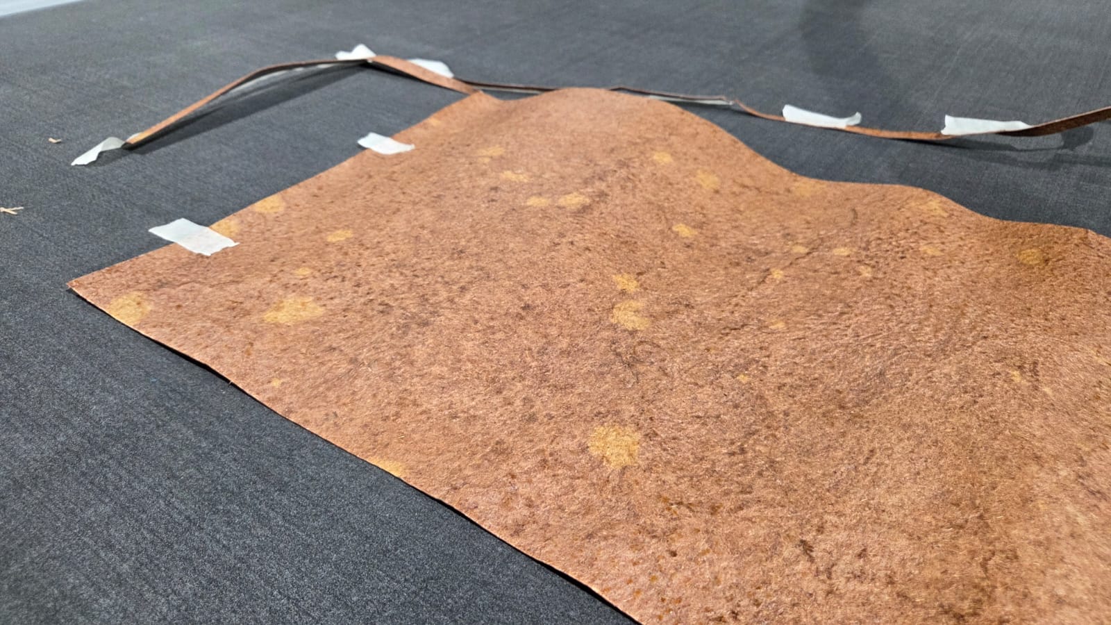
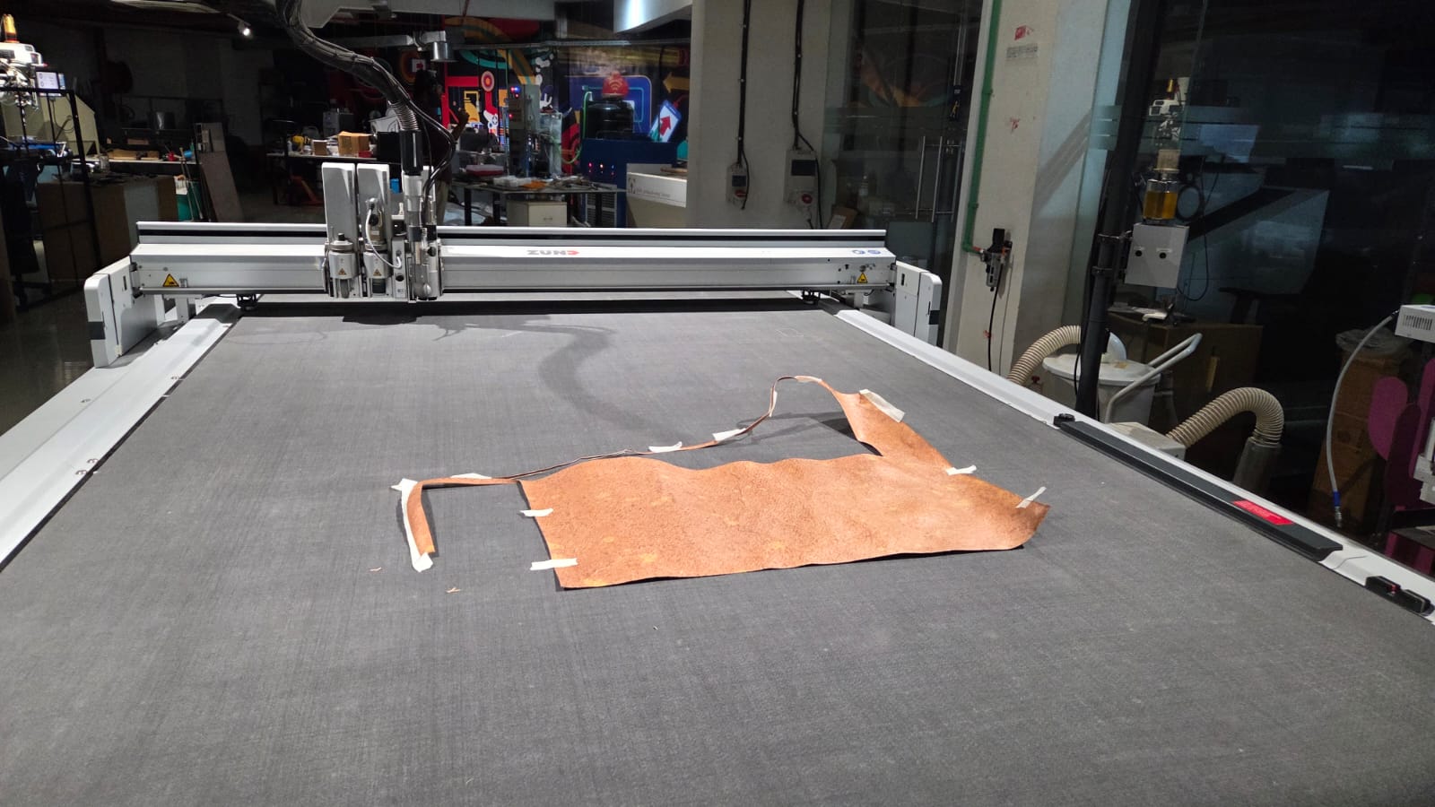
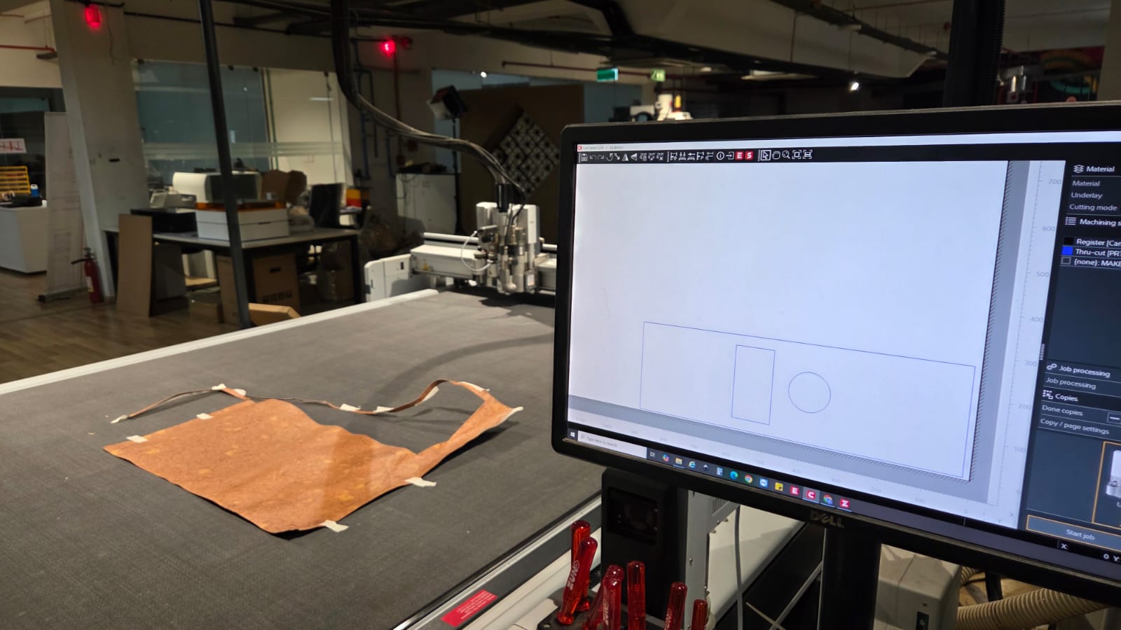
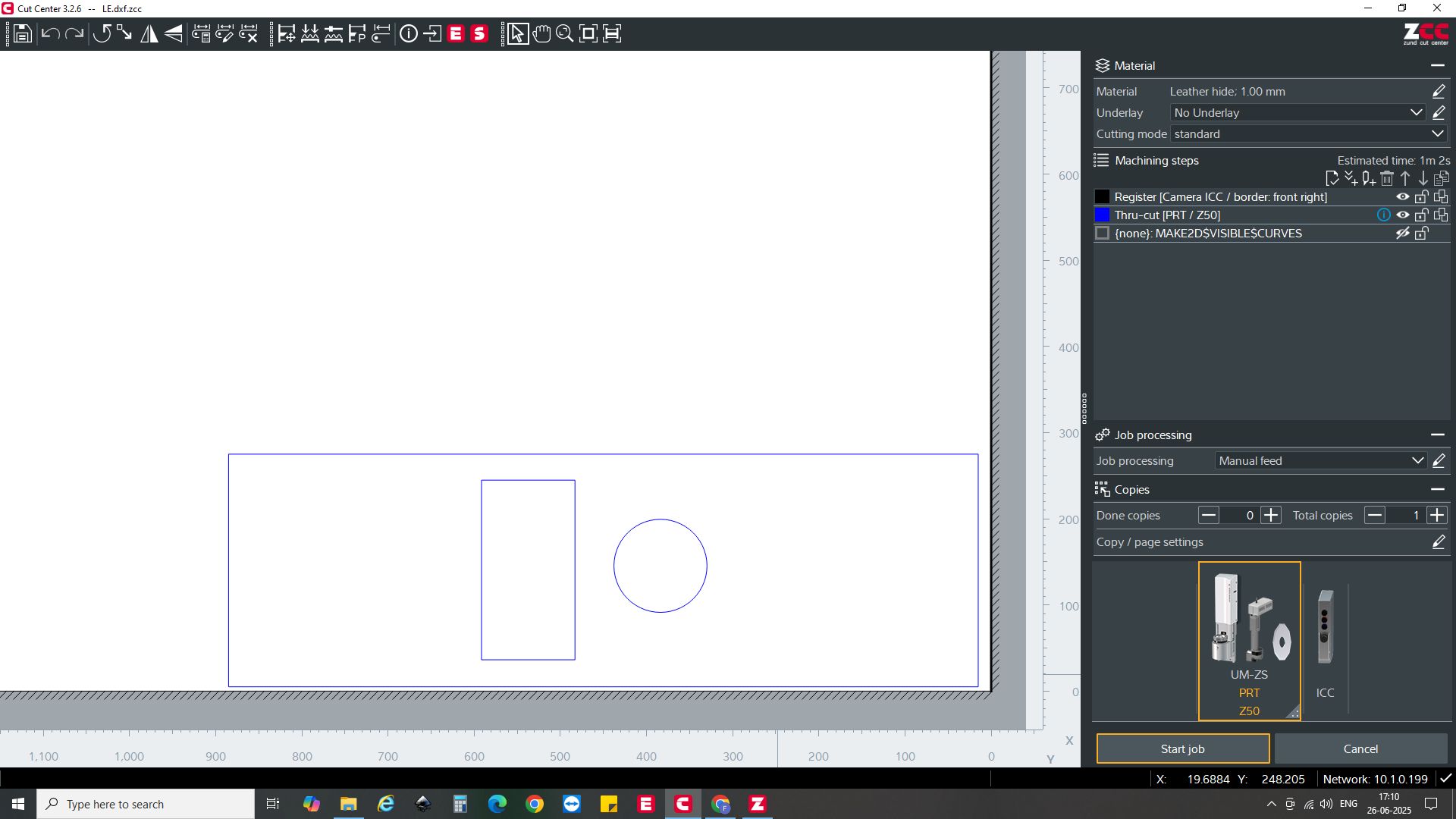
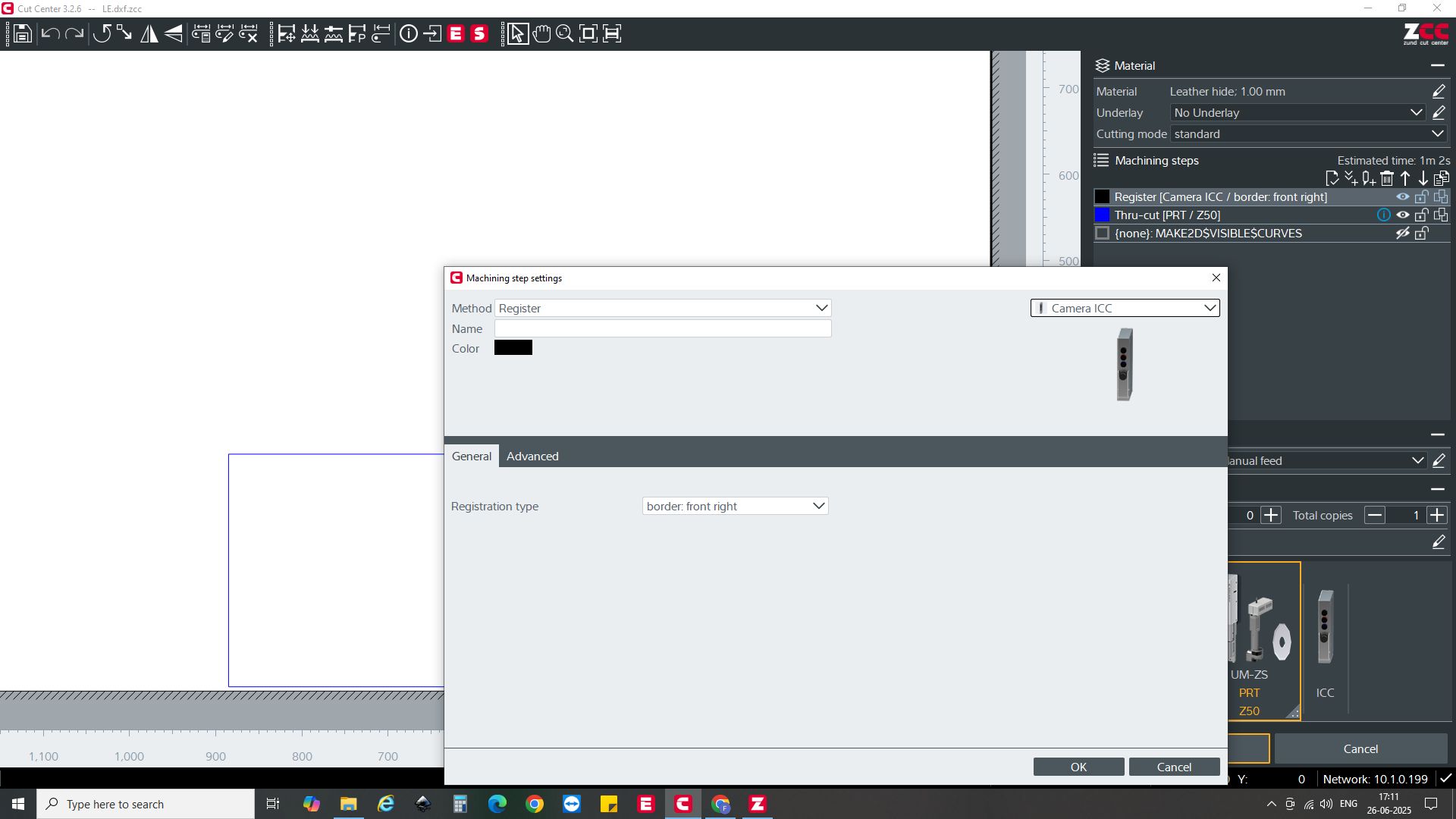
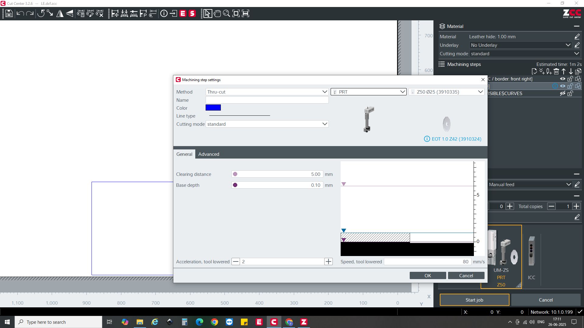
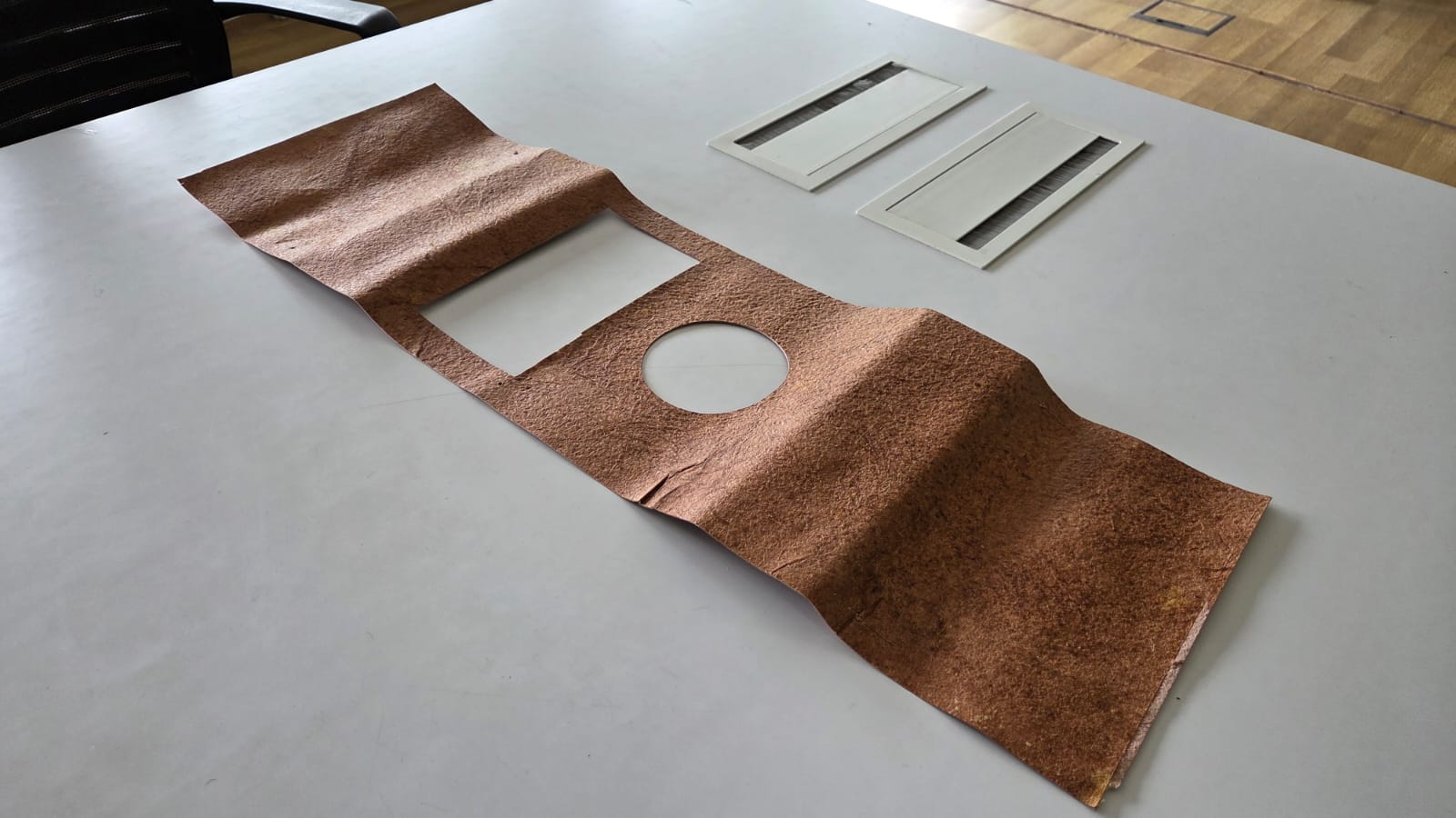
Leather Cutting
This is the video of the vegan leather cutting on the Zund Flat Bed Cutter. I used the Malai.eco Vegan Coconut Leather to finish Symphoni. I cut the leather using the Zund Flat Bed Cutter.
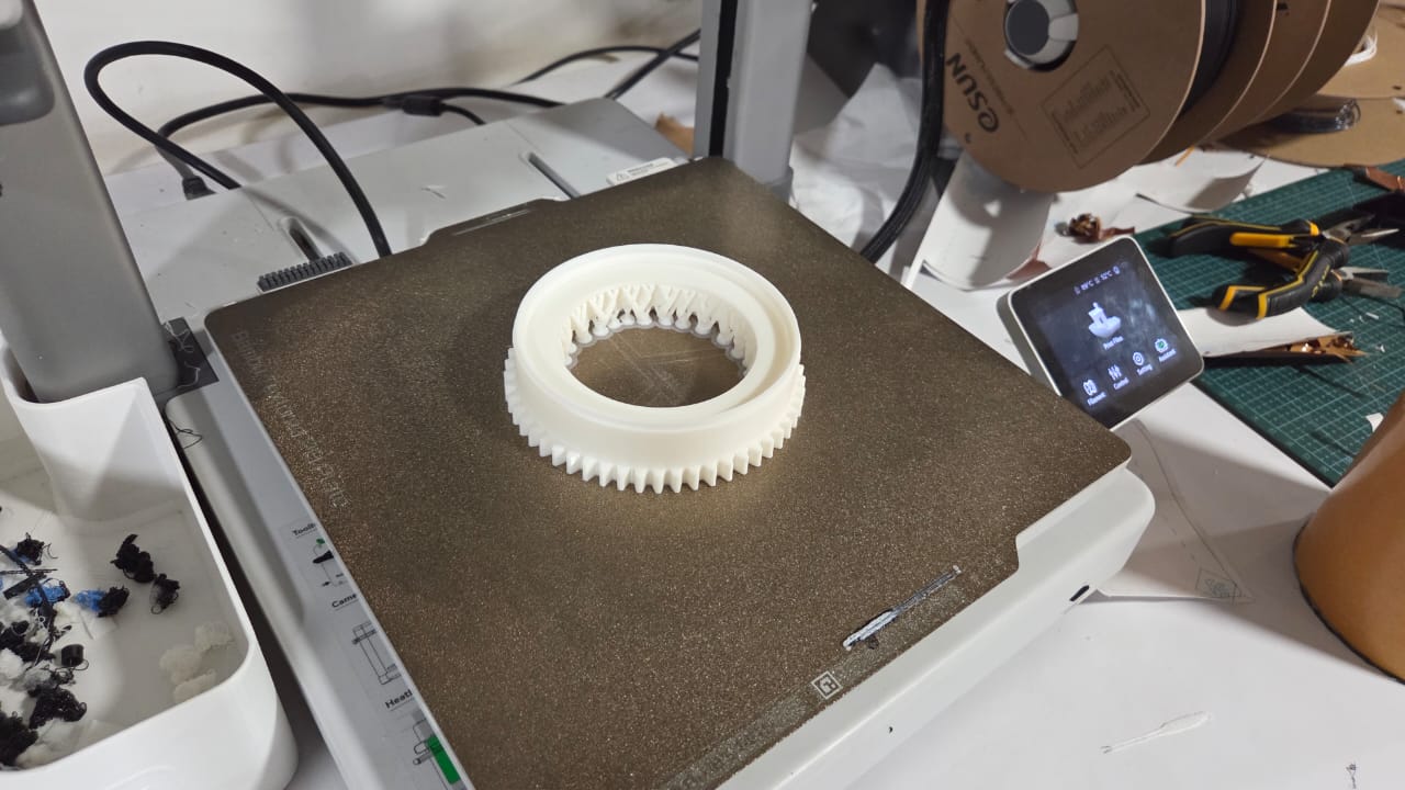
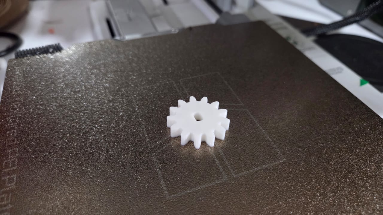
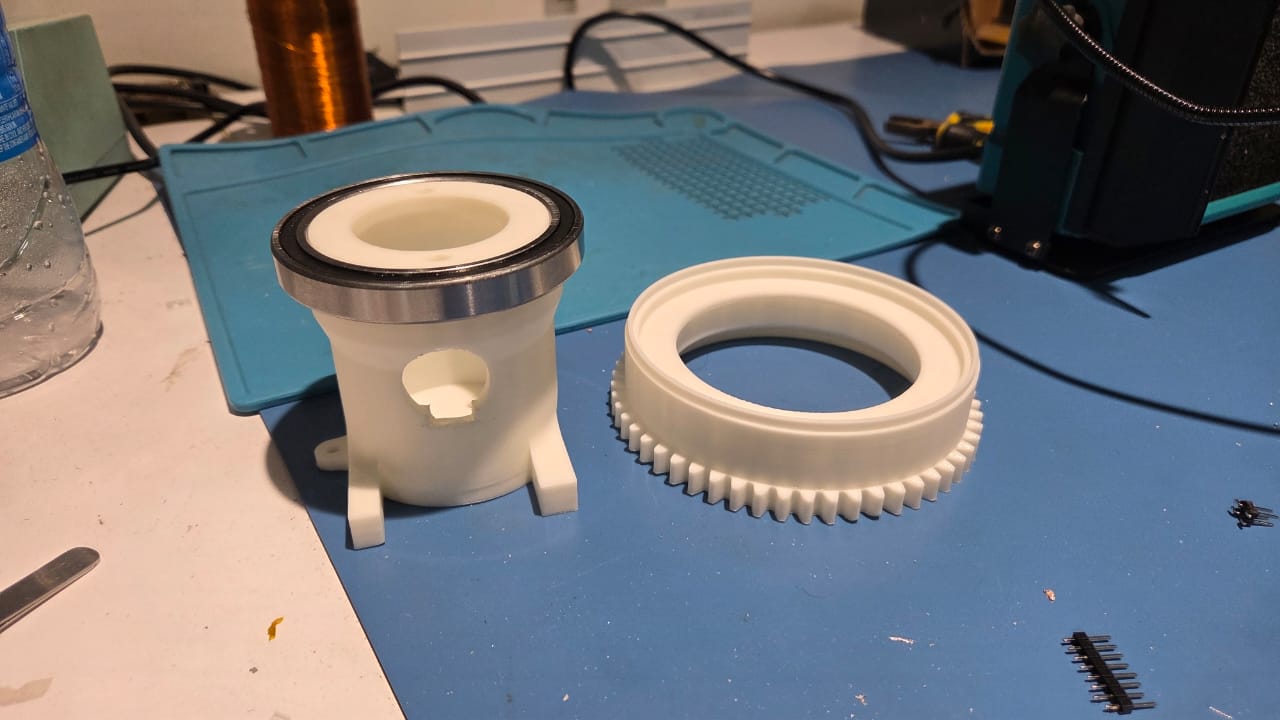
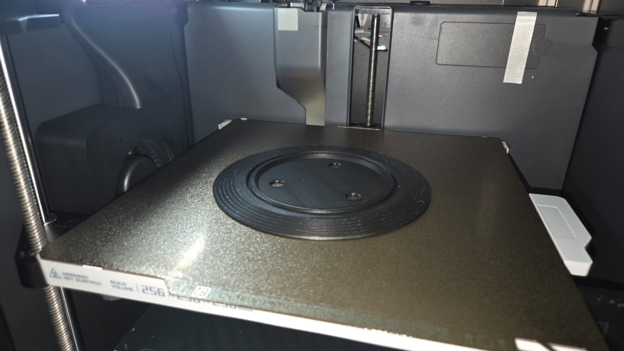
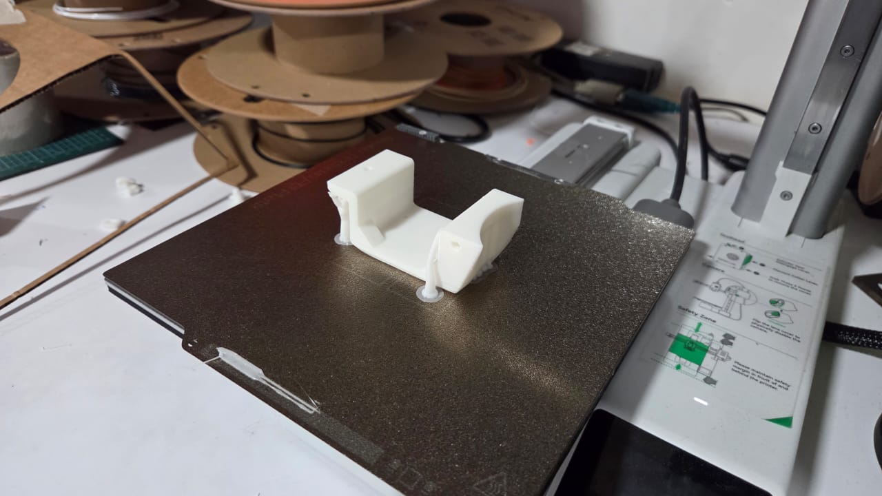
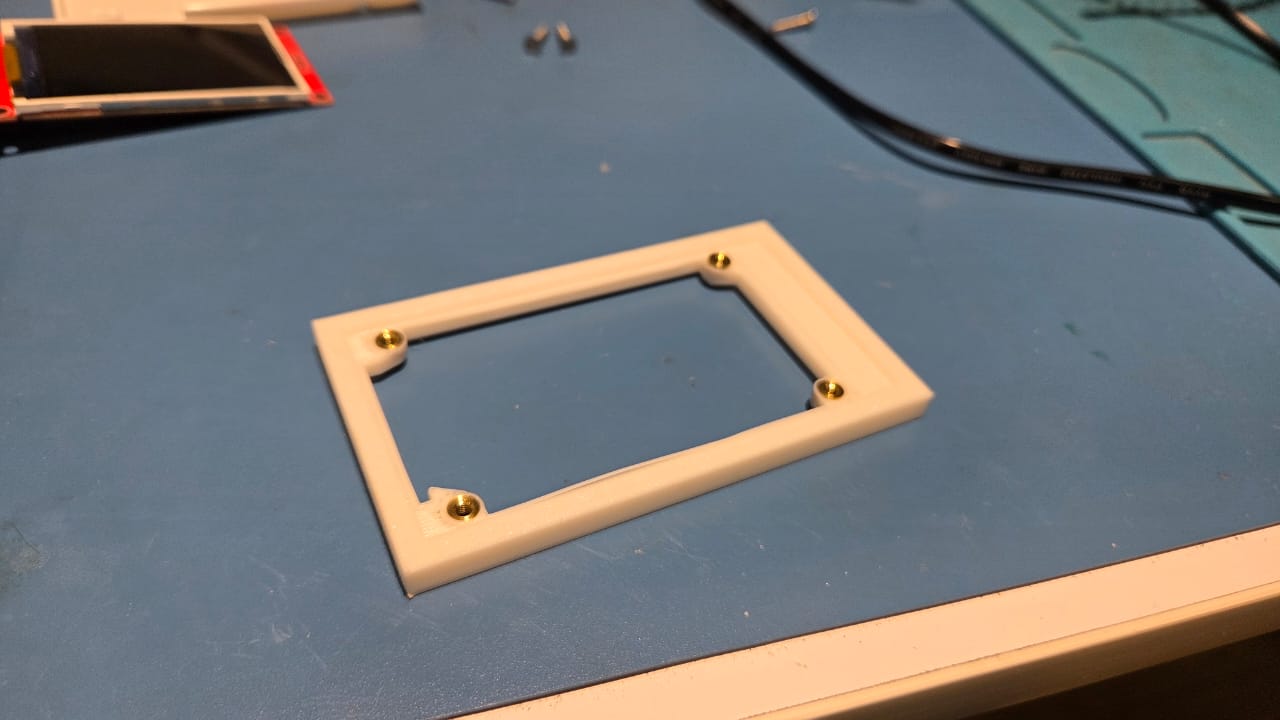
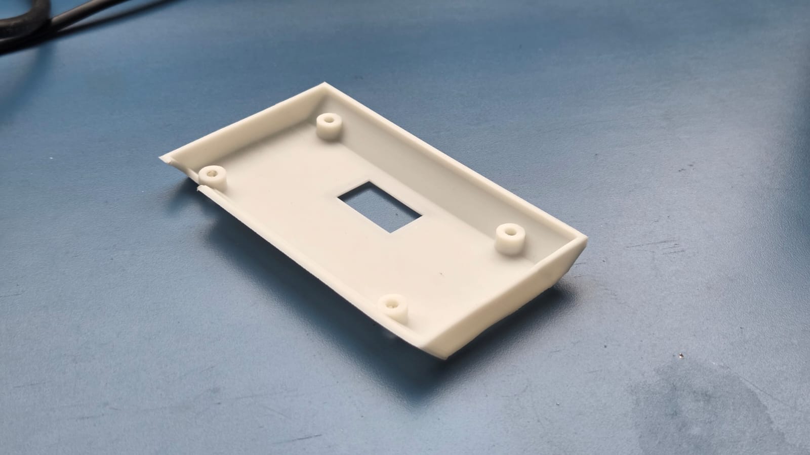
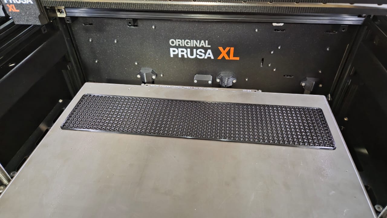
3D Printing
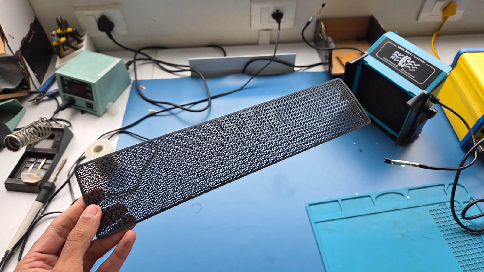
Laser Cutting and Engraving
I used the Trotec Laser Engraver mainly for 3 things:
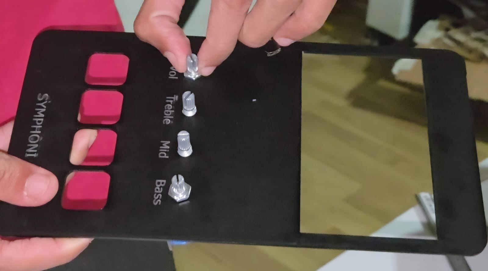
- Control Panel
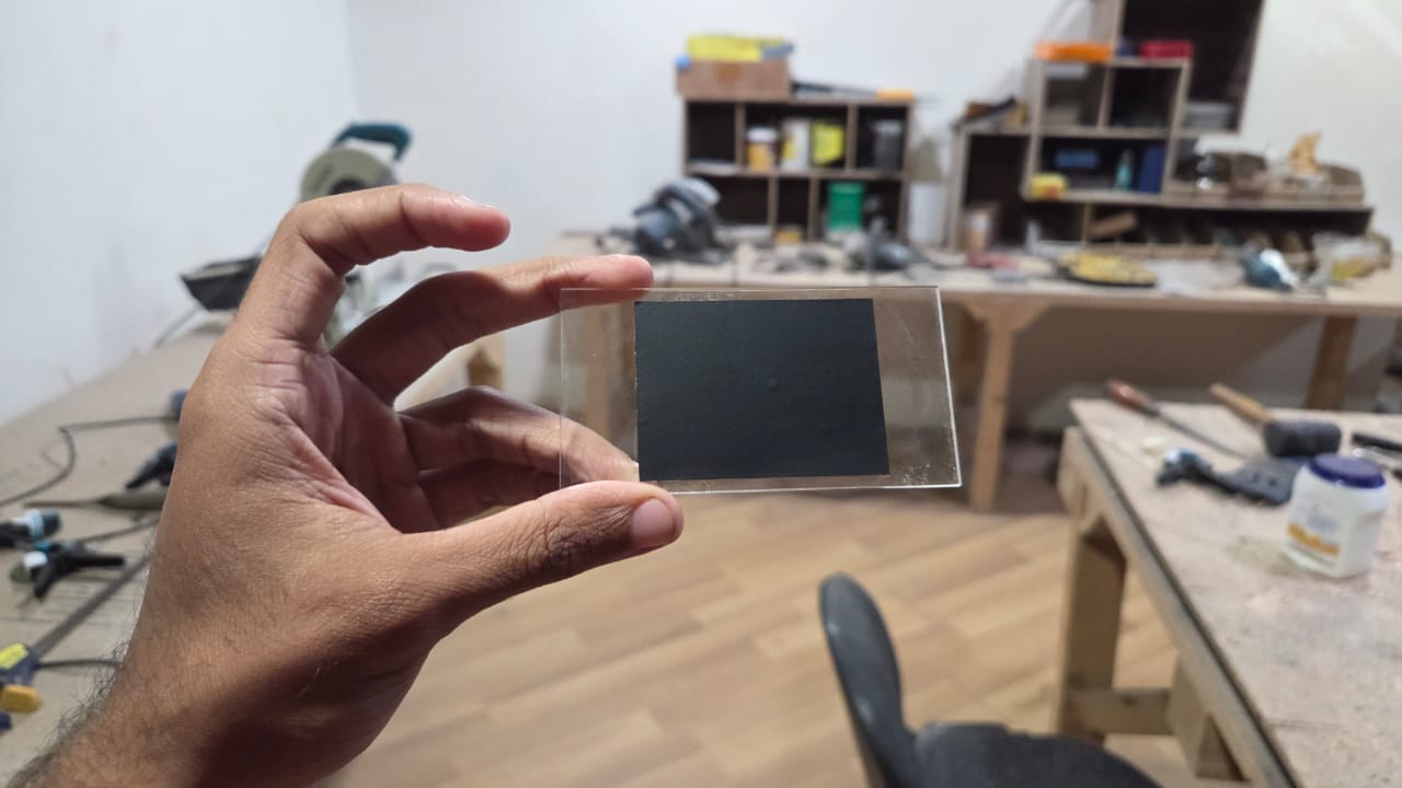
- Acrylic Record
- Acrylic Front Screen
I engraved and cut a Matt Black 2mm Acrylic Sheet for my control panel which consisted of cutouts for the display unit, Tone Control Knobs and Playback Buttons. Below video shows a glimpse of the laser engraving and cutting of the Control Panel.
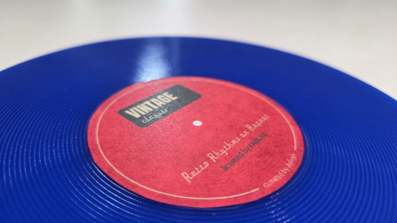
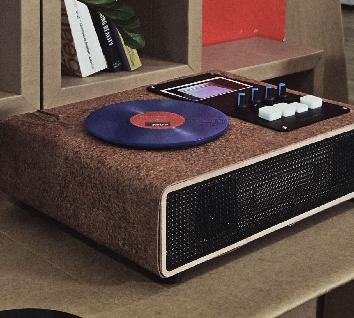
I used black, blue and red acrylic sheets to form the Acrylic Records. The Records basically were designed with a lot of concentric lines mimicking the lines on record. The lines were engraved on the acrylic. They serve no functional purpose but do enhance the aesthetic appeal of the record.
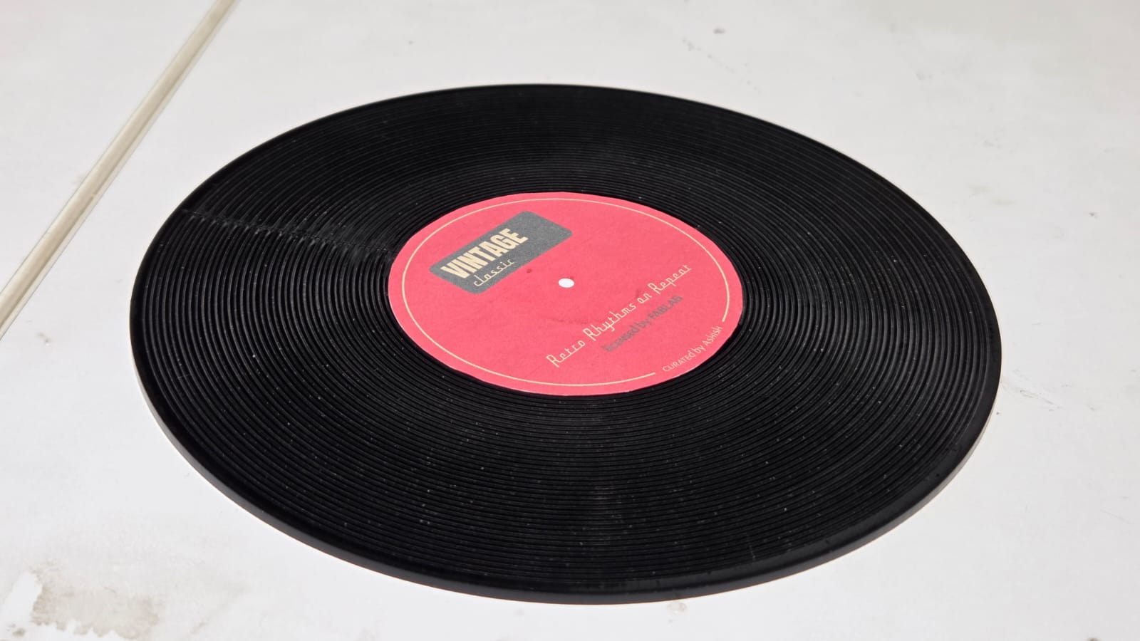
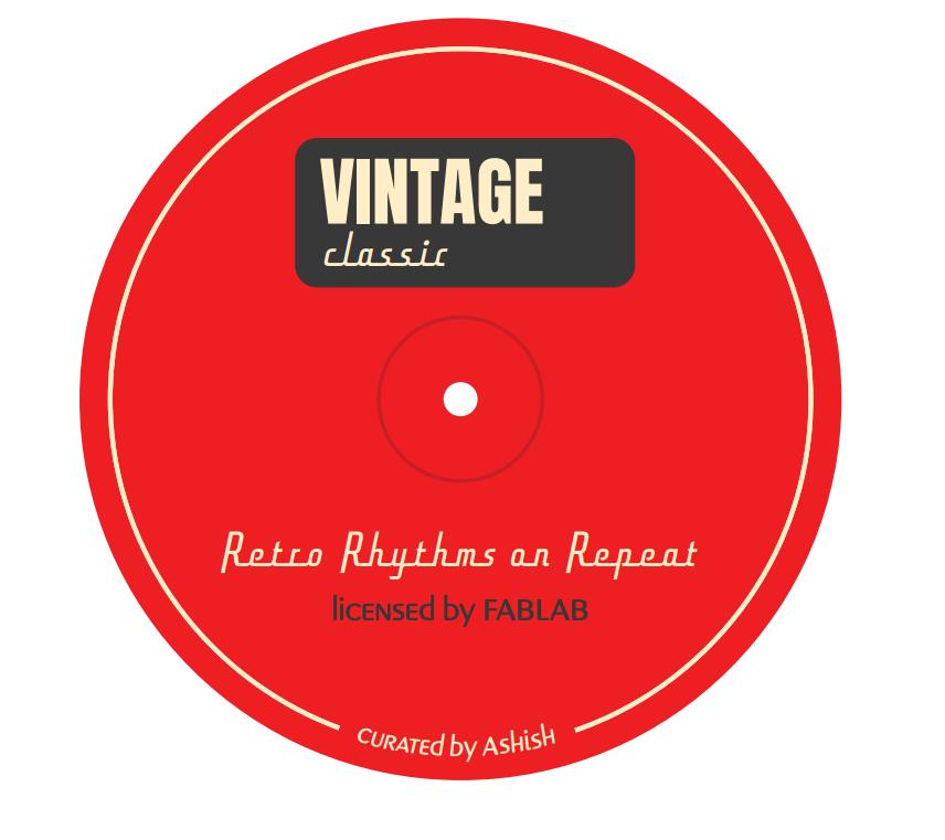
The record has to house a NFC Sticker Tag on it which will store the Spotify UPI. Therefore, I needed a center sticker to hide the NFC Sticker. Balasankar from the lab helped me with the design of the Sticker.
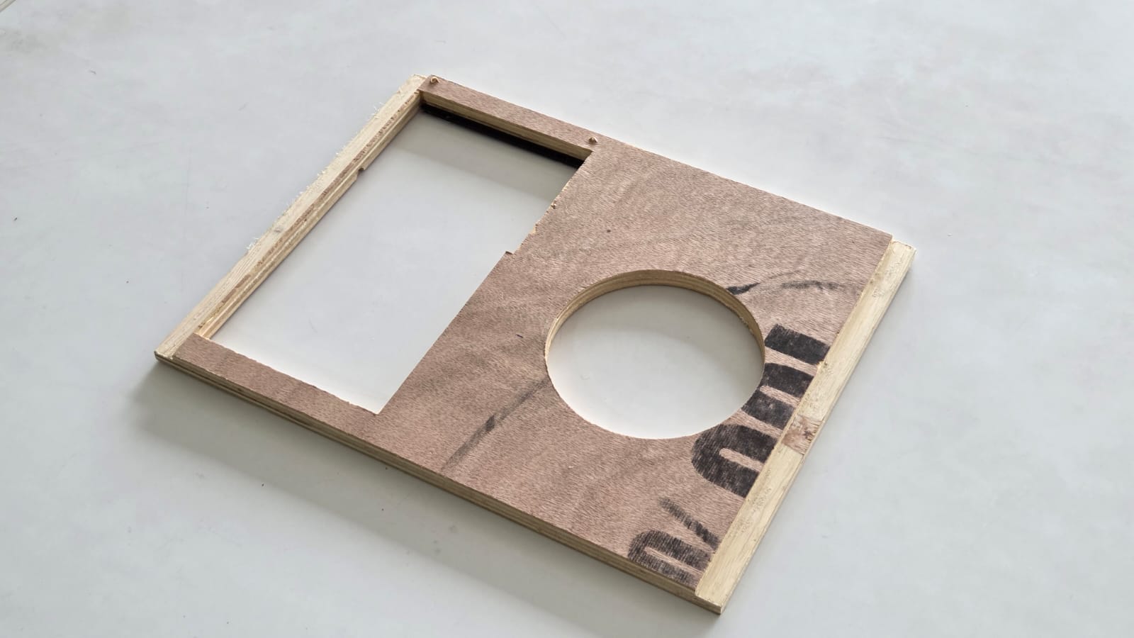
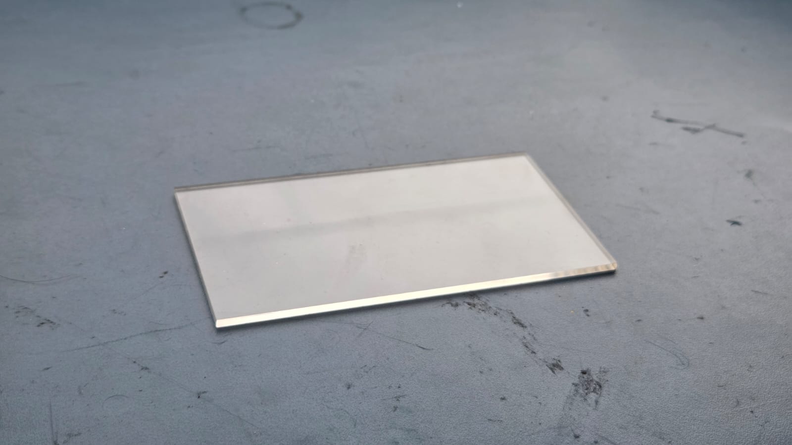
The front panel for the display was cut from clear acrylic according to the dimensions of the display module which I designed. The acrylic cut piece would be press fit from top of the 3D Printed Display Case.
Vinyl Cutting
For the front panel of the display unit, I wanted to have a flush screen which could blend with the LCD Display panel. For that I decide to use a Clear Acrylic and use a vinyl sticker as a placeholder to spray paint the rest of the acrylic.
The below video shows the vnyl cutting process using the Roland GS-24 vinyl cutter. I exported the design from Fusion360 as a DXF File and using Inkscape and the mods software made a cutout for the placeholder. The vinyl cutter cuts the design on the vinyl sheet, which is then applied to the acrylic panel. The vinyl sticker acts as a mask for spray painting, allowing for a clean and professional finish on the acrylic panel.
The vinyl cutter is not accurate and there is a mismatch with the cut acrylic. I didn't have time to correct the error and redesign the design. That's why I manually removed the center portion(placeholder) and stuck it on the acrylic cutout.
After sticking it, I applied Matt Black Spray paint on the acryclic cutout and left it to dry for an hour. After the paint dried up, I removed the vinyl, leaving a beautiful front panel for my display unit.
Assembly


PRogramming
The programming was already done in the previous weeks as part of the final project
#include "AudioTools.h"
#include "BluetoothA2DPSink.h"

I2SStream i2s;
BluetoothA2DPSink a2dp_sink(i2s);

void setup() {
  auto cfg = i2s.defaultConfig();
  cfg.pin_bck = 27;
  cfg.pin_ws = 12;
  cfg.pin_data = 14;
  i2s.begin(cfg);

  a2dp_sink.start("Symphoni2");
}

void loop() {
}
This is the fianl code that allows me to control playback using the NFC Tags and also connect to the Symphoni App to write the NFC Tags through the RFID Reader.
#include <Arduino.h>
#include <WiFi.h>
#include <SpotifyEsp32.h>
#include <WebServer.h>
#include <SPI.h>
#include <MFRC522.h>

const char* ssid = "SSID Name";  //replace with your WiFi SSID
const char* password = "SSID PAssword"; //replace with your WiFi Password

const char* CLIENT_ID = "Spotify CLIENT ID"; //replace with your Spotify Client ID
const char* CLIENT_SECRET = "Spotify CLIENT SECRET"; 	//replace with your Spotify Client Secret
const char* REFRESH_TOKEN = "Spotify Refresh Token"; //replace with your Spotify Refresh Token

#define RST_PIN 13
#define SS_PIN   5

#define motor 27

MFRC522 mfrc522(SS_PIN, RST_PIN);

Spotify sp(CLIENT_ID, CLIENT_SECRET,REFRESH_TOKEN);

WebServer server(80);

String receivedUri = "";  // <- store latest URI
bool writePending = false; // <- flag to indicate pending write


void setup() {

  pinMode(motor, OUTPUT);


  Serial.begin(115200);
  SPI.begin();
  mfrc522.PCD_Init();

  connect_to_wifi();

  server.on("/uri", HTTP_POST, handleUriPost);
  server.begin();
  Serial.println("HTTP server started");

  sp.begin();

  while(!sp.is_auth()){
    sp.handle_client();
  }

  Serial.println("Authenticated");
}

void loop() {
  server.handleClient();

  if (writePending) {
    write_nfc();
  }

  read_nfc();

    mfrc522.PICC_HaltA();
    mfrc522.PCD_StopCrypto1();
    delay(3000);

}

void connect_to_wifi(){
    WiFi.begin(ssid, password);
    Serial.print("Connecting to WiFi...");
    while (WiFi.status() != WL_CONNECTED) {
        delay(1000);
        Serial.print(".");
    }
    Serial.printf("\nConnected to WiFi\n");
    Serial.println(WiFi.localIP());
}

void handleUriPost() {
  if (server.hasArg("uri")) {
    receivedUri = server.arg("uri");
    writePending = true;  // mark that we need to write
    Serial.println("Received URI: " + receivedUri);
    server.send(200, "text/plain", "URI received: " + receivedUri);
  } else {
    server.send(400, "text/plain", "Missing 'uri' parameter");
  }
}

void write_nfc(){
  Serial.println("Waiting for NFC card to write...");

    MFRC522::MIFARE_Key key;
    for (byte i = 0; i < 6; i++) key.keyByte[i] = 0xFF;  // Default key

    if (!mfrc522.PICC_IsNewCardPresent()) return;
    if (!mfrc522.PICC_ReadCardSerial()) return;

    Serial.print(F("Card UID: "));
    for (byte i = 0; i < mfrc522.uid.size; i++) {
      Serial.print(mfrc522.uid.uidByte[i] < 0x10 ? " 0" : " ");
      Serial.print(mfrc522.uid.uidByte[i], HEX);
    }
    Serial.println();

    // Prepare data
    byte buffer1[16];
    byte buffer2[16];
    const char* playlistID = receivedUri.c_str();
    size_t len = strlen(playlistID);

    // Fill buffer1 with first 16 bytes
    for (byte i = 0; i < 16; i++) {
      buffer1[i] = (i < len) ? playlistID[i] : ' ';
    }

    // Fill buffer2 with next 16 bytes (if any)
    for (byte i = 0; i < 16; i++) {
      byte index = i + 16;
      buffer2[i] = (index < len) ? playlistID[index] : ' ';
    }

    // Write to block 1
    byte block = 1;
    MFRC522::StatusCode status;
    status = mfrc522.PCD_Authenticate(MFRC522::PICC_CMD_MF_AUTH_KEY_A, block, &key, &(mfrc522.uid));
    if (status != MFRC522::STATUS_OK) {
      Serial.print(F("Auth failed for block 1: "));
      Serial.println(mfrc522.GetStatusCodeName(status));
      return;
    }
    status = mfrc522.MIFARE_Write(block, buffer1, 16);
    if (status != MFRC522::STATUS_OK) {
      Serial.print(F("Write failed for block 1: "));
      Serial.println(mfrc522.GetStatusCodeName(status));
      return;
    }
    Serial.println(F("Block 1 written successfully."));

    // Write to block 2
    block = 2;
    status = mfrc522.PCD_Authenticate(MFRC522::PICC_CMD_MF_AUTH_KEY_A, block, &key, &(mfrc522.uid));
    if (status != MFRC522::STATUS_OK) {
      Serial.print(F("Auth failed for block 2: "));
      Serial.println(mfrc522.GetStatusCodeName(status));
      return;
    }
    status = mfrc522.MIFARE_Write(block, buffer2, 16);
    if (status != MFRC522::STATUS_OK) {
      Serial.print(F("Write failed for block 2: "));
      Serial.println(mfrc522.GetStatusCodeName(status));
      return;
    }
    Serial.println(F("Block 2 written successfully."));

    mfrc522.PICC_HaltA();
    mfrc522.PCD_StopCrypto1();

    Serial.println(F("Done writing Spotify ID!"));

    writePending = false;  // clear the flag after writing
    delay(3000);
}

void read_nfc(){
  MFRC522::MIFARE_Key key;
    for (byte i = 0; i < 6; i++) key.keyByte[i] = 0xFF;  // Default key

    if (!mfrc522.PICC_IsNewCardPresent()) return;  //skip everything if the card present is not new
    if (!mfrc522.PICC_ReadCardSerial()) return;    //skip everything if the card is new but the data is same

    Serial.print(F("Card UID: "));
    for (byte i = 0; i < mfrc522.uid.size; i++) {
      Serial.print(mfrc522.uid.uidByte[i] < 0x10 ? " 0" : " ");
      Serial.print(mfrc522.uid.uidByte[i], HEX);
    }
    Serial.println();

    byte buffer1[18];  // 16 bytes + 2 for CRC
    byte size = sizeof(buffer1);
    byte block;

    // Read block 1
    block = 1;
    if (!authenticateAndRead(block, buffer1, size, key)) return;

    // Read block 2
    block = 2;
    byte buffer2[18];
    size = sizeof(buffer2);
    if (!authenticateAndRead(block, buffer2, size, key)) return;

    // Combine both buffers into one string
   char context_uri[64]; // 32 + null terminator
    for (int i = 0; i < 16; i++) {
      context_uri[i] = (char)buffer1[i];
      context_uri[i + 16] = (char)buffer2[i];
    }
    context_uri[32] = '\0'; // null terminator

    // Trim trailing spaces
    for (int i = 31; i >= 0; i--) {
      if (context_uri[i] == ' ') {
        context_uri[i] = '\0';
      } else {
        break;
      }
    }
    char final_uri[80];
    snprintf(final_uri, sizeof(final_uri), "spotify:%s", context_uri);  //concatenating 'spotify:playlist:'+'context_uri' into 'final_uri'

    Serial.print(F("Context URI: "));
    Serial.println(final_uri);

response resp = sp.start_resume_playback(final_uri, 0, 0, nullptr); //send the put message to play the final_uri

if (resp.status_code == 204 || resp.status_code == 200) {
    Serial.println(F("Playback started successfully!"));
    analogWrite(motor, 40);
} else {
    Serial.print(F("Failed to start playback. HTTP code: "));
    Serial.println(resp.status_code);
}
    // Serial.print(F("Playlist ID: "));
    // Serial.println(context_uri);

}

bool authenticateAndRead(byte block, byte *buffer, byte &size, MFRC522::MIFARE_Key &key) {
    MFRC522::StatusCode status;

    status = mfrc522.PCD_Authenticate(MFRC522::PICC_CMD_MF_AUTH_KEY_A, block, &key, &(mfrc522.uid));
    if (status != MFRC522::STATUS_OK) {
      Serial.print(F("Authentication failed for block "));
      Serial.print(block);
      Serial.print(F(": "));
      Serial.println(mfrc522.GetStatusCodeName(status));
      return false;
    }

    status = mfrc522.MIFARE_Read(block, buffer, &size);
    if (status != MFRC522::STATUS_OK) {
      Serial.print(F("Read failed for block "));
      Serial.print(block);
      Serial.print(F(": "));
      Serial.println(mfrc522.GetStatusCodeName(status));
      return false;
    }

    return true;
}
Testing
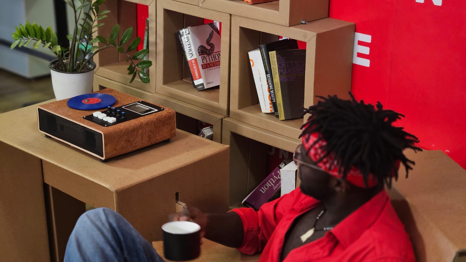
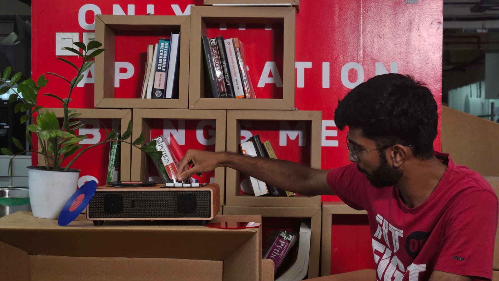
I tested the Symphoni project by playing music from my smartphone via Bluetooth. The NFC tags on the turntable allowed me to control playback and switch tracks.
Finishing the look
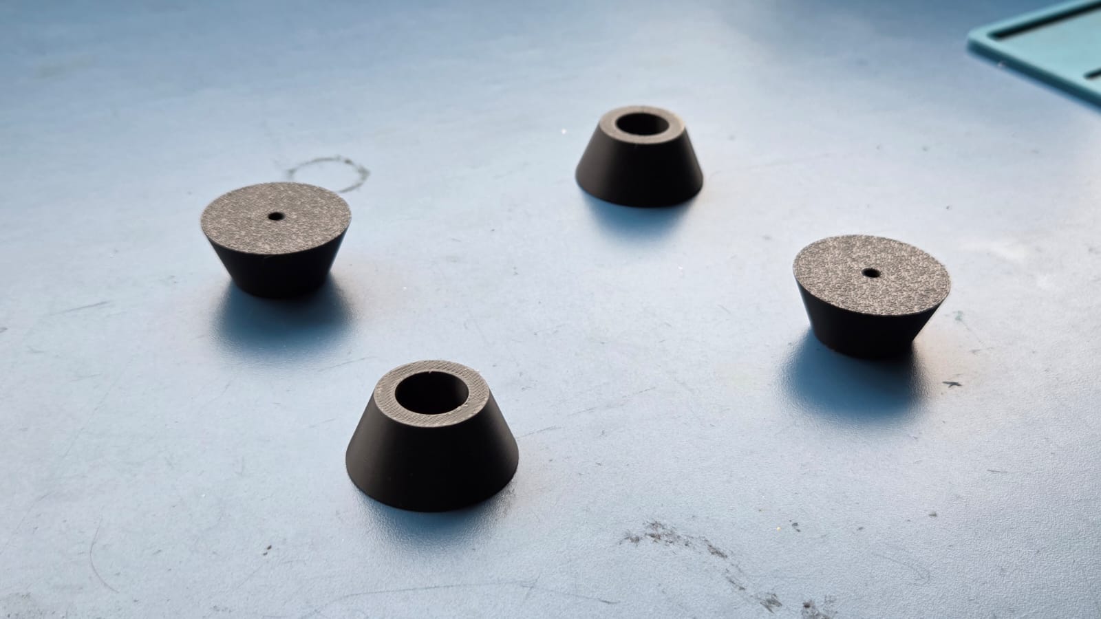
I stuck the vegan leather on the body of the Symphoni using double sided tape for the scope of the project. Mufeed, Midhun and Amal helped me to give Symphoni its finished look. Adding the leather and the 3D printed Standoffs was the highlight of project giving it that aesthetic.
Result
The below image is of our Academic Intern Kenneth from MIT who was ready to model for my project.