
Networking and Communications
This week, I focused on designing, fabricating, and assembling a custom PCB. I used KiCad for schematic and PCB design, then fabricated the board using milling and laser etching, and finally assembled and tested it.
Learning Objectives
Assignments
Group Assignments
Individual Assignments
Group Assignment
The group assignment was to communicate between any 2 projects already made. For the assignment purpose, we communicated between my and Ancy's project. The commnication between the two projects was done by ESP-NOW as both are boards were XIAO ESP32s. You can find the group assignment on the below page.
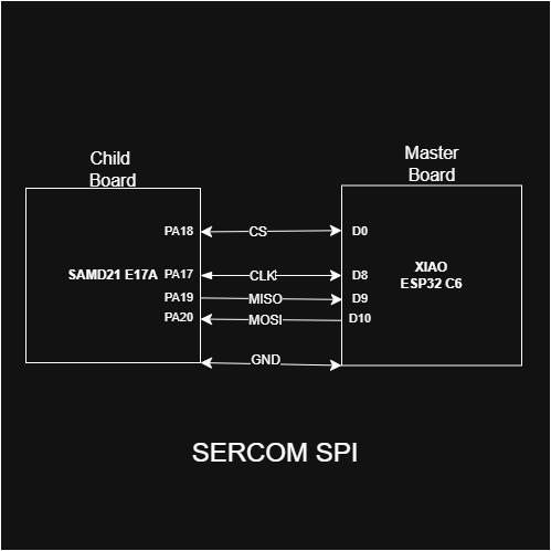
Group AssignmentSPI ESP32C6-SAMD21
SERCOM
Generally a microcontroller will have separate serial communication modules with different pinouts for each module. Separate dedicated peripherals and user registers will be available for each module. For example, USART will be a separate peripheral with dedicated pins for its function and I2C will be a separate peripheral with its own dedicated pins.
In SAM D microcontrollers, all the serial peripherals are designed into a single module as serial communication interface (SERCOM). A SERCOM module can be configured either as USART, I2C, or SPI, selectable by the user. Each SERCOM will be assigned four pads from PAD0 to PAD3. The functionality of each pad is configurable depending on the SERCOM mode used. Unused pads can be used for other purposes and the SERCOM module will not control them unless they are configured to be used by the SERCOM module.
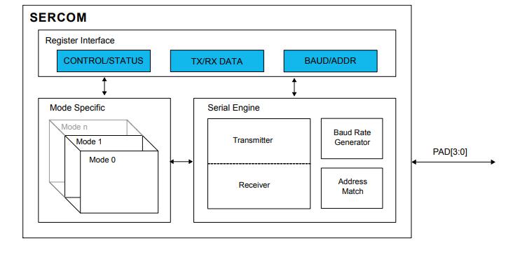
Photo credit: Microchip
For example, SERCOM0 can be configured as USART mode with PAD0 as transmit pad and PAD1 as receive pad. Other unused pads (PAD2 and PAD3) can be used either as GPIO pins or be assigned to some other peripherals. The assignment of SERCOM functionality for different pads is highly flexible making the SERCOM module more advantageous compared to the typical serial communication peripheral implementation
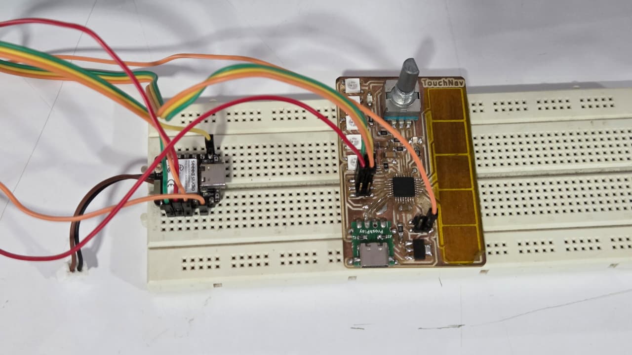
In this assignment, I used the SERCOM SPI Library to communicate between the SAMD21 and ESP32C6 Boards. The ESP32C6 Board acts as the master and the SAMD21 Board acts as the child in the SPI Communication.
For more information about the SERCOM SPI Library, you can refer to the GitHub repository.
Sercom SPI Slave LibraryI used this library for my SAMD21 Board to communicate it as a Child
I took this example code from the above given github repository to initialize the SAMD21 Board as the child in the SPI Communication. I have edited the code for the correct pins in my case for my SAMD21 Board. You can find the detailed documentation of the TouchNav SAMD21 Board in the input week assignment.
/*
  Copyright (C) 2022 lenvm

  This program is free software: you can redistribute it and/or modify
  it under the terms of the GNU General Public License as published by
  the Free Software Foundation, either version 3 of the License, or
  (at your option) any later version.

  This program is distributed in the hope that it will be useful,
  but WITHOUT ANY WARRANTY; without even the implied warranty of
  MERCHANTABILITY or FITNESS FOR A PARTICULAR PURPOSE.  See the
  GNU General Public License for more details.

  For the GNU General Public License see https://www.gnu.org/licenses/

  Contact Information
  -------------------
  lenvm
  GitHub   : https://github.com/lenvm
*/

/*
  Example code for the SercomSPISlave library.
  This code initializes a SERCOM1 SPI Child and prints the data received.

  Written 2020 July 15
  by lenvm
  Updated 2021 June 8
  by lenvm
  Updated 2022 November 1
  by lenvm
*/

#include <SercomSPISlave.h>
Sercom1SPISlave SPISlave; // to use a different SERCOM, change this line and find and replace all SERCOM1 with the SERCOM of your choice

#define DEBUG // uncomment this line to print debug data to the serial bus
#define INTERRUPT2BUFFER // uncomment this line to copy the data received in the Data Received Complete interrupt to a buffer to be used in the main loop
//#define INTERRUPT2SERIAL // uncomment this line to print the data to the serial bus whenever the Data Received Complete interrupt is triggered

// initialize variables
byte buf[1]; // initialize a buffer of 1 byte

void setup()
{
  Serial.begin(115200);
  Serial.println("Serial started");
  SPISlave.SercomInit(SPISlave.MOSI_Pins::PA16, SPISlave.SCK_Pins::PA17, SPISlave.SS_Pins::PA18, SPISlave.MISO_Pins::PA19);
  Serial.println("SERCOM1 SPI child initialized");
}

void loop()
{
  #ifdef INTERRUPT2BUFFER
    Serial.println(buf[0]); // Print latest data written into the buffer by the interrupt
    delay(1); // Delay of 1 ms
  #endif
  #ifdef INTERRUPT2SERIAL
    delay(1000); // Delay of 1 s to keep the main loop running, while data is written to the serial every time the Data Received Interrupt is triggered
  #endif
}

void SERCOM1_Handler()
/*
Reference: Atmel-42181G-SAM-D21_Datasheet section 26.8.6 on page 503
*/
{
  #ifdef DEBUG
    Serial.println("In SPI Interrupt");
  #endif
  uint8_t data = 0;
  data = (uint8_t)SERCOM1->SPI.DATA.reg;
  uint8_t interrupts = SERCOM1->SPI.INTFLAG.reg; // Read SPI interrupt register
  #ifdef DEBUG
    Serial.print("Interrupt: "); Serial.println(interrupts);
  #endif

  // Child Select Low interrupt
  if (interrupts & (1 << 3)) // 1000 = bit 3 = SSL // page 503
  {
    #ifdef DEBUG
      Serial.println("SPI Child Select Low interupt");
    #endif
    SERCOM1->SPI.INTFLAG.bit.SSL = 1; // Clear Child Select Low interrupt
  }

  // Data Received Complete interrupt: this is where the data is received, which is used in the main loop
  if (interrupts & (1 << 2)) // 0100 = bit 2 = RXC // page 503
  {
    #ifdef DEBUG
      Serial.println("SPI Data Received Complete interrupt");
    #endif
    data = SERCOM1->SPI.DATA.reg; // Read data register
    SERCOM1->SPI.INTFLAG.bit.RXC = 1; // Clear Receive Complete interrupt
  }

  // Data Transmit Complete interrupt
  if (interrupts & (1 << 1)) // 0010 = bit 1 = TXC // page 503
  {
    #ifdef DEBUG
      Serial.println("SPI Data Transmit Complete interrupt");
    #endif
    SERCOM1->SPI.INTFLAG.bit.TXC = 1; // Clear Transmit Complete interrupt
  }

  // Data Register Empty interrupt
  if (interrupts & (1 << 0)) // 0001 = bit 0 = DRE // page 503
  {
    #ifdef DEBUG
      Serial.println("SPI Data Register Empty interrupt");
    #endif
    SERCOM1->SPI.DATA.reg = 0xAA;
  }

  #ifdef INTERRUPT2BUFFER
    // Write data to buffer, to be used in main loop
    buf[0] = data;
  #endif
  #ifdef INTERRUPT2SERIAL
    // Print data received during the Data Receive Complete interrupt
    char _data = data;
    Serial.print("DATA: ");
    Serial.println(_data); // Print received data
  #endif

}
This is the master code for the XIAO ESP32C6 Board that I used for communicating with the TouchNav SAMD21 Board. I used ChatGPT to write this code.
ChatGPT Prompt: I want to communicate between a SAMD21 and a XIAO ESP32-C6 using SPI. The ESP32-C6 will act as the SPI master and send integer data to the SAMD21 (SPI child). The data should be sent when I type a number into the Serial Monitor and press Enter.
#include

#define SCK  D8
#define MISO D10
#define MOSI D9
#define CS   D0

void setup() {
  Serial.begin(115200);

  SPI.begin(SCK, MISO, MOSI, CS);
  pinMode(CS, OUTPUT);
  digitalWrite(CS, HIGH);
}

void loop() {
  delay(1000);  // Every 1 sec send data


    if (Serial.available()) {
    String inputString = Serial.readStringUntil('\n');  // read till Enter key
    int response = inputString.toInt();  // convert to integer
    digitalWrite(CS, LOW);
    SPI.transfer(response);  // Send 0x55 and read response

    Serial.print("You entered: ");
    Serial.println(response);

    digitalWrite(CS, HIGH);
  }


}
Individual Assignments
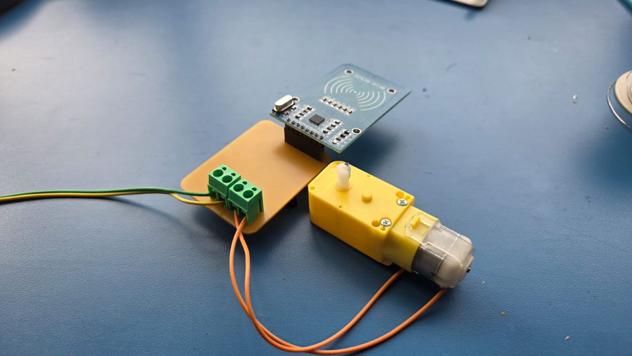
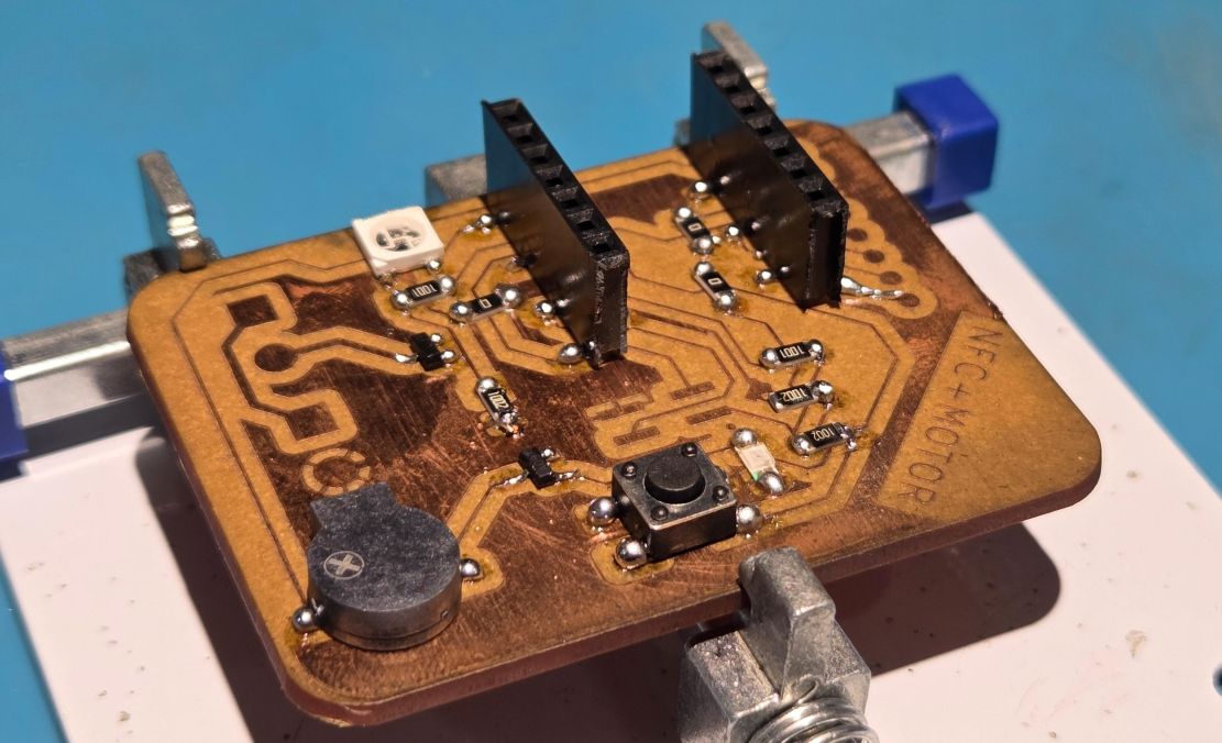
NFC + Motor Board
I wanted to design a board which used RFID communication as it was required for my final project. This week was the best time to try the MRFC522 RFID Reader Module. I also wanted to control a motor according to the RFID Input. This would help me to integrate in the final project.
I also wanted to try using my boards to communicate using Morse Code. That's why I added a push button and a speaker/buzzer to the board.
Designing the board
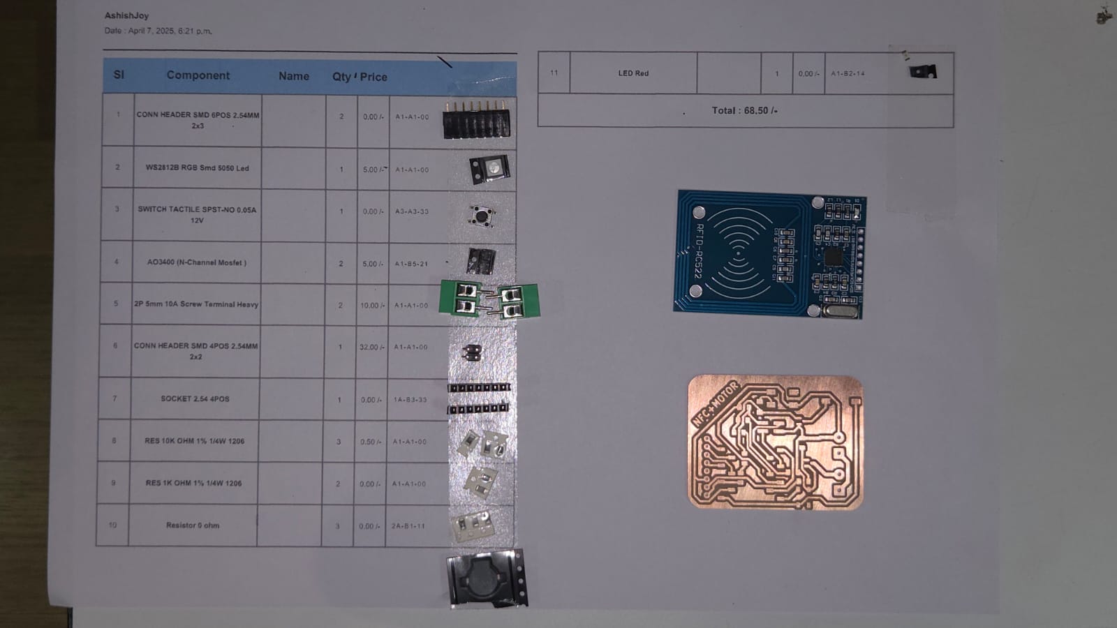
Components Used
- RFID RC522 Dev Kit
- DC Motor
- Speaker
- Push Button
- WS2812B LED
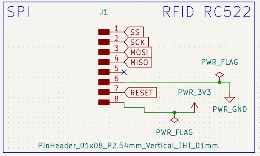
RFID-RC522 Development Kit
This RC522 RFID Development kit is based on NXP's a highly integrated reader/writer IC MFRC522 for contactless communication at 13.56 MHz. The MFRC522 reader supports ISO/IEC 14443 A/MIFARE and NTAG. The MFRC522's internal transmitter is able to drive a reader/ writer antenna designed to communicate with ISO/IEC 14443A cards and transponders without additional active circuitry. The receiver module provides a robust and efficient implementation for demodulating and decoding signals from ISO/IEC 14443A compatible cards and transponders.
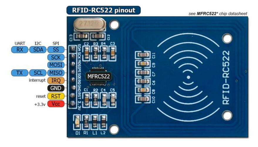
Photo credit: handsontec
- Operating Voltage: 2.5V~3.3V.
- Operating/Standby current: 13~26mA/10~13mA.
- Operating Frequency: 13.56MHz.
- Supports ISO/IEC 14443A higher transfer speed communication up to 848 KBd.
- SPI bus speed up to 10Mbit/s.
- I2C-bus interface up to 400 kBd in Fast mode, up to 3400 kBd in High-speed mode.
- RS232 Serial UART up to 1228.8 kBd, with voltage levels dependant on pin voltage supply.
- Compatible with MIFARE and ISO 14443A cards.
- Typical operating distance in Read/Write mode up to 50 mm depending on the antenna size and tuning.
I used the SPI protocol to communicate with the RFID RC522 Development Board as it offered maximum speed. I have used a 1x8 Through Hole Header Array to connect the RC522 Board.
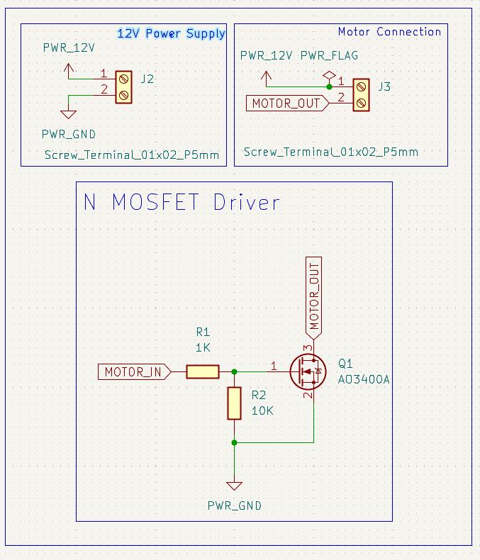
DC Motor with N Channel Mosfet
For my final project, I need a motor to rotate the record to mimic the turntable effect of the classic Vinyl Record Player. I didn't need any complex motor control, so I decide to make a simple DC Motor circuit driven by a simple N Channel Mosfet.
I refered to Akash's documentation to design my motor driver circuit
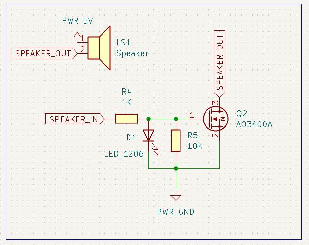
Speaker
For this week's assignment , I wanted to make a Wifi based Morse Code communication board. For a typical Morse Code Machine the sound is very essential, that's why I wanted to use a speaker/buzzer for the board. So I decide to use the speaker that Namita used for her last week's assignment as it required a simple driver circuit which is MOSFET based unlike my I2S DAC+Amplifier Based Circuit which used for my assignment last week. The AST0927MW-3.6Q Speaker is an electromagnetic transducer which is specifically designed for audio indication, with a resonant frequency of 2.73 kHz and a sound pressure level (SPL) of 85 dB. I used the footprint provided by Namita which she made last week. You can refer to her documentation for more information about the speaker and how she made the footprint.
The footprint of the AST0927MW-3.6Q Speaker is attached here - Speaker Footprint
The speaker also uses a N Channel Mosfet as a driver. I have attached a Red LED to the Speaker-In pin through a resistor, this makes it light up by default everytime the speaker is on, making it easier for me. I didn't have to use a pin or program the LED Separately.
WS2812B and Push Button
The WS2812B Addressable RGB LED is also used to signify the status of the board and the push button is used to send morse code messages. The push button is pulled up hy by a resistor to avoid floating values.
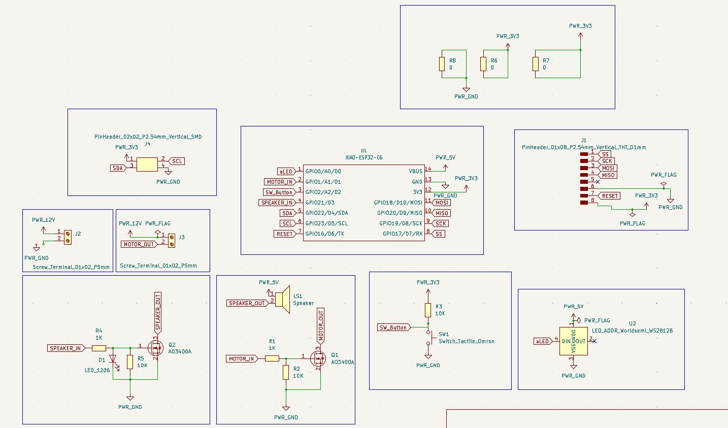
NFC Motor Board Schematic
The schematic and PCB design was doen in the KiCad Software.
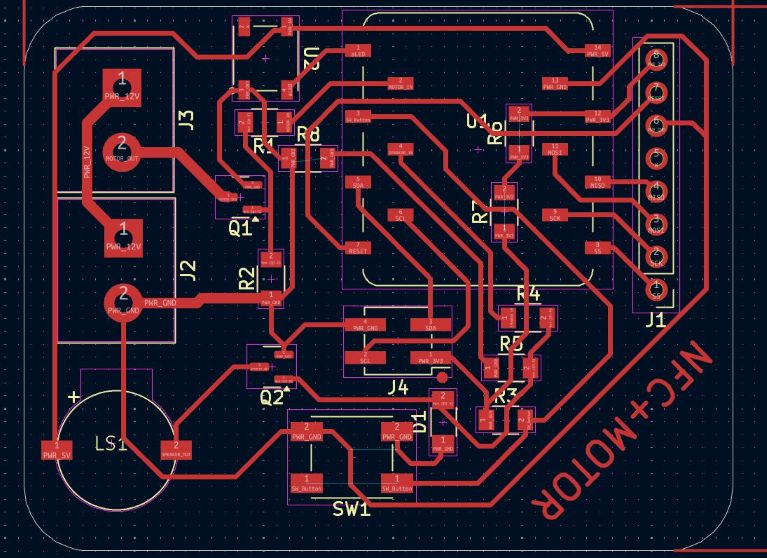
NFC Motor Board PCB Design
This is the PCB Design of the board. I edited the trace width of the 12V and GND lines to carry more current. The trace width of those power lines is 0.8mm whiile rest of the trace widths are 0.4 mm.
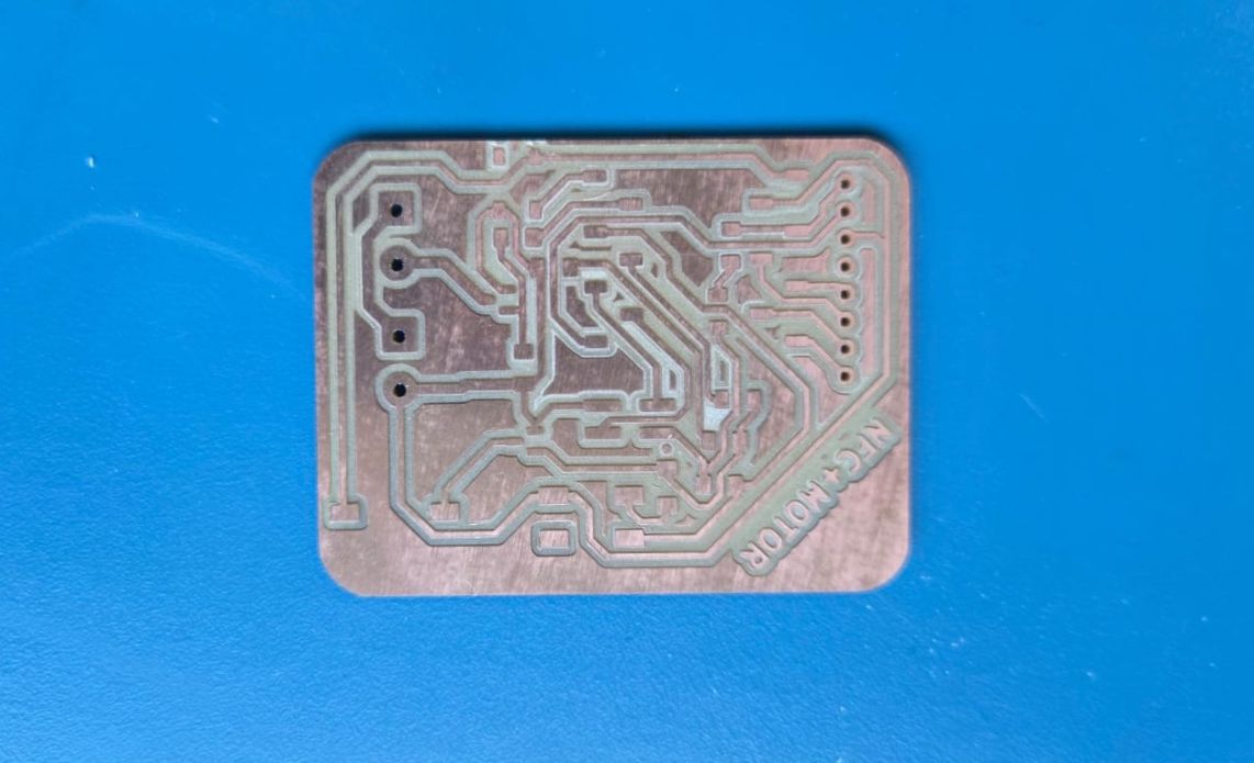
PCB Milling using Milling Machine
I used the Modela RDX Milling Machine for milling the PCB
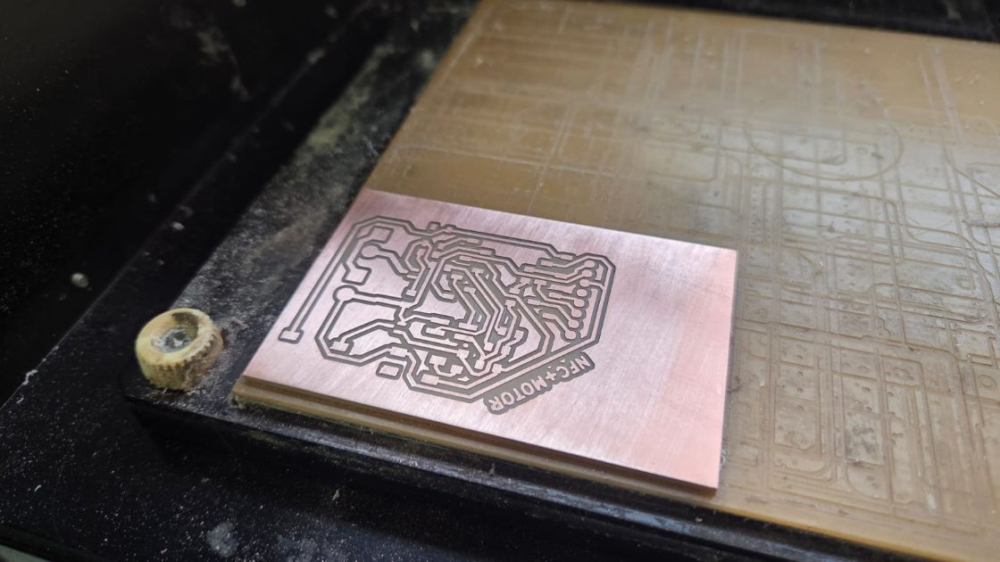
The traces were clean and the board was ready to be assembled using all the components.
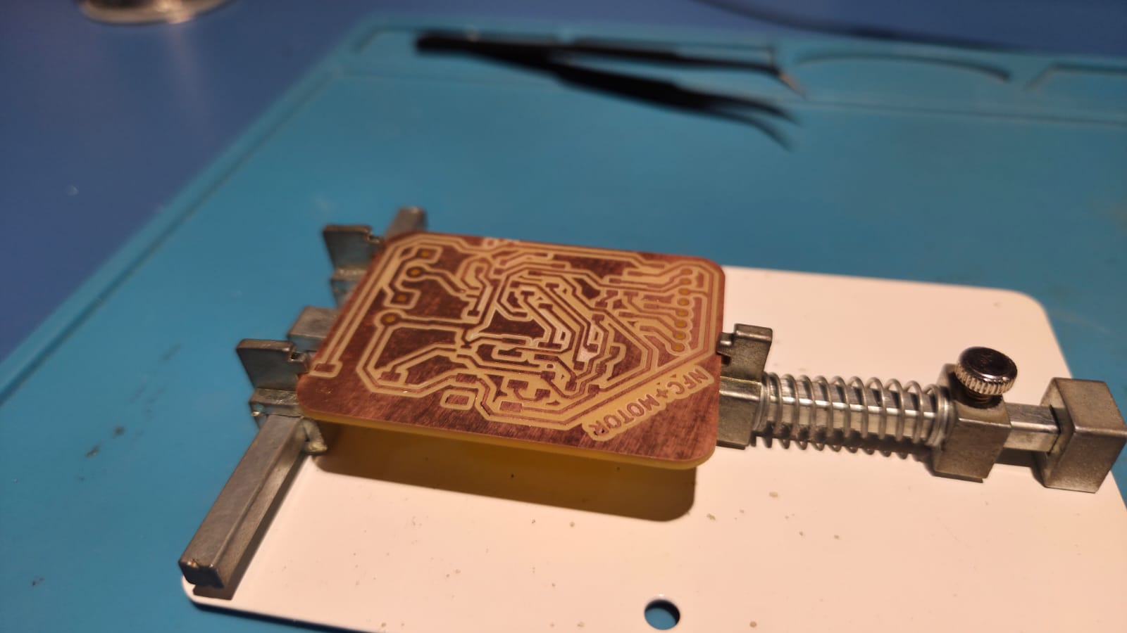
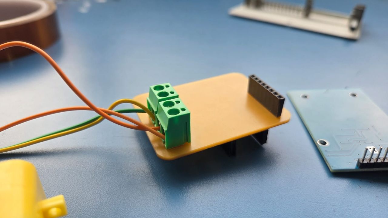
Assembly
I setup the board on the PCB holder setup and requested all the components from the Fab Stash and collected it from the inventory.
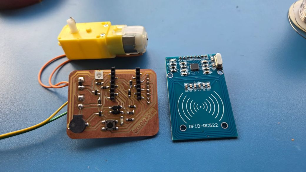
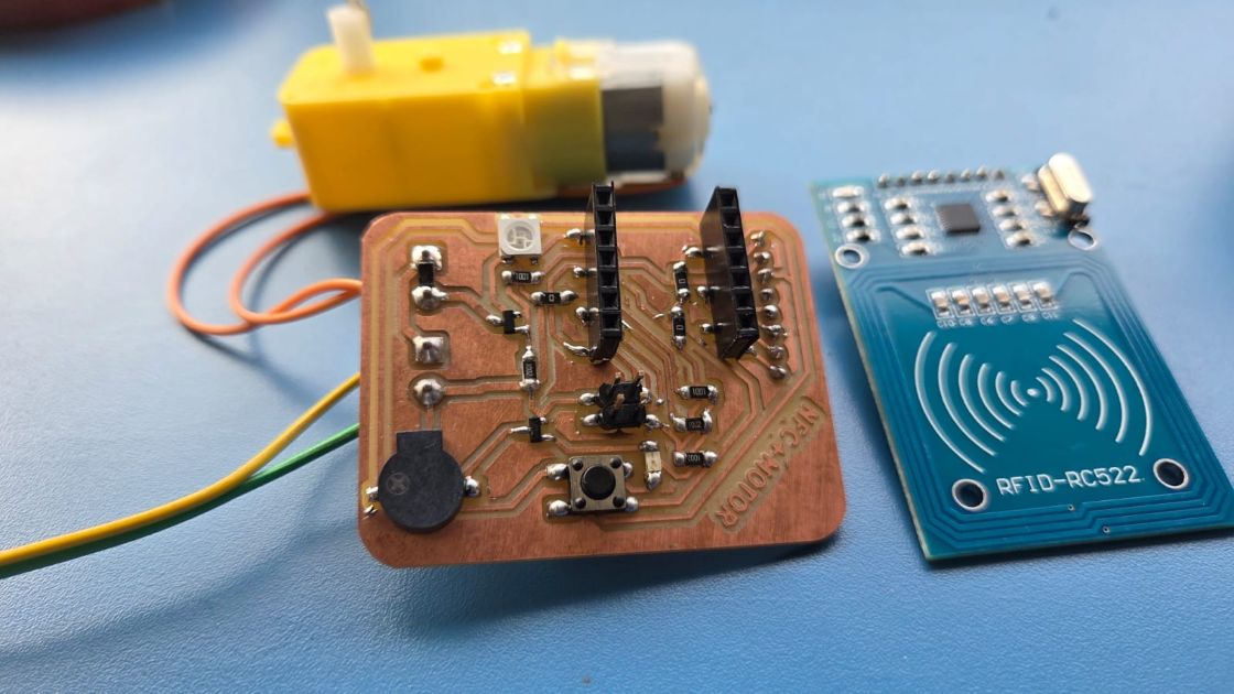
Hero Shots
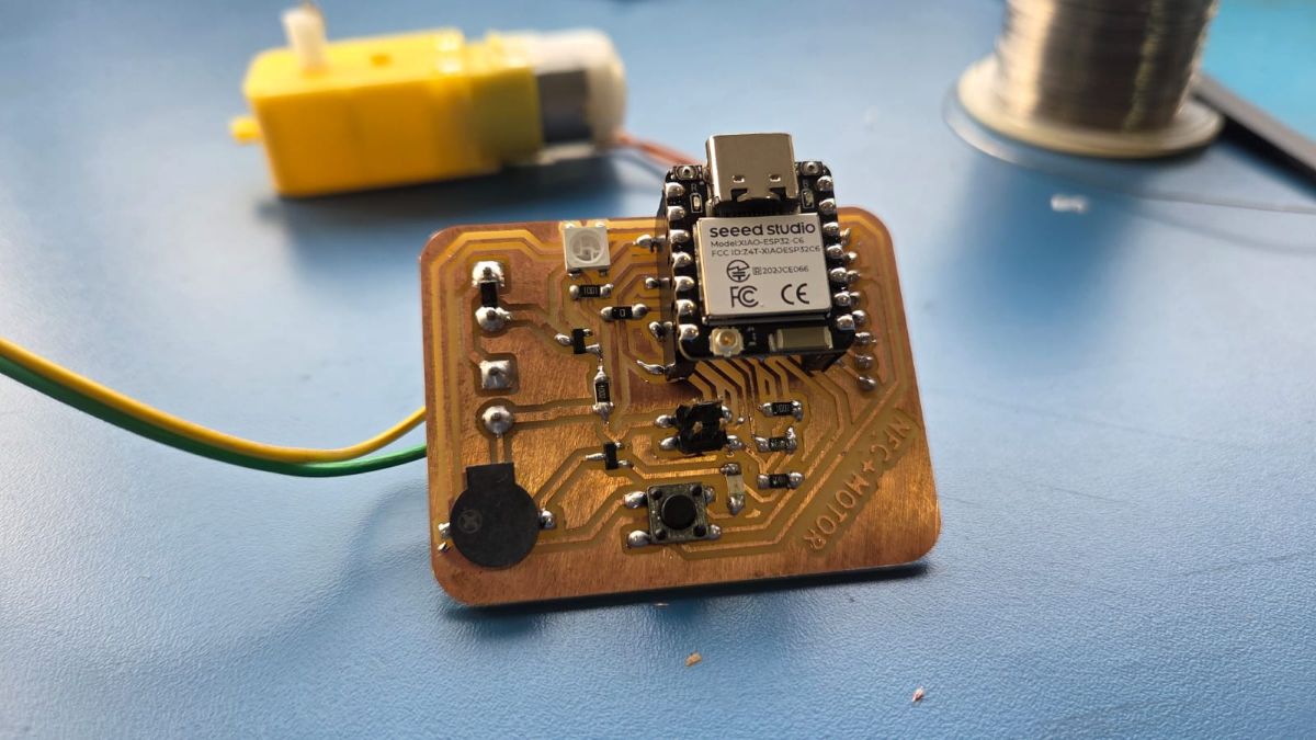
After soldering all the components on the PCB, I attached the motor and the RC522 RFID Reader Module to the board. Below are some hero shots of the board.
PCB Engraving using XTools F1 Ultra
After the milling the board on the Modela RDX Milling machine, I wanted to try using another process for my next PCB. I used the XTools F1 Ultra for my next board.
Electroncis Production: Group AssignmentYou can refer to the above documentation on the process of PCB engraving using the XTools F1 Ultra in the 'Using the XTool F1 Ultra for PCB Engraving' section.
YOu have to import the Trace Outline in the XTools Creative Studio and Trace it.
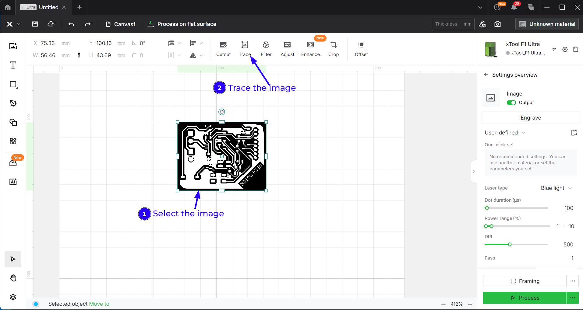
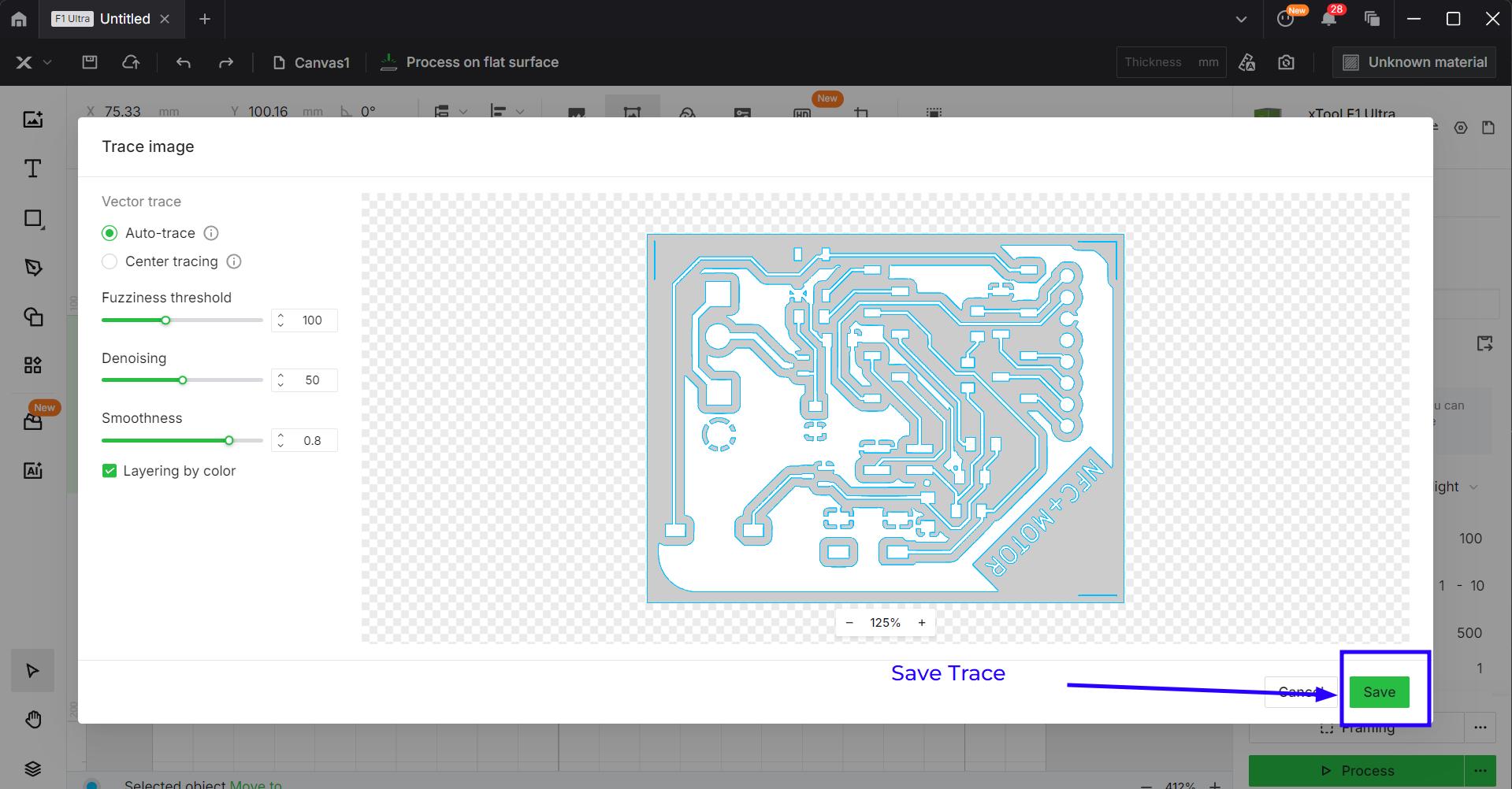
The Trace Window creates a vector image from the imported image which can be engraved or scored. I wanted to engrave it for this purpose. Click the Save button.
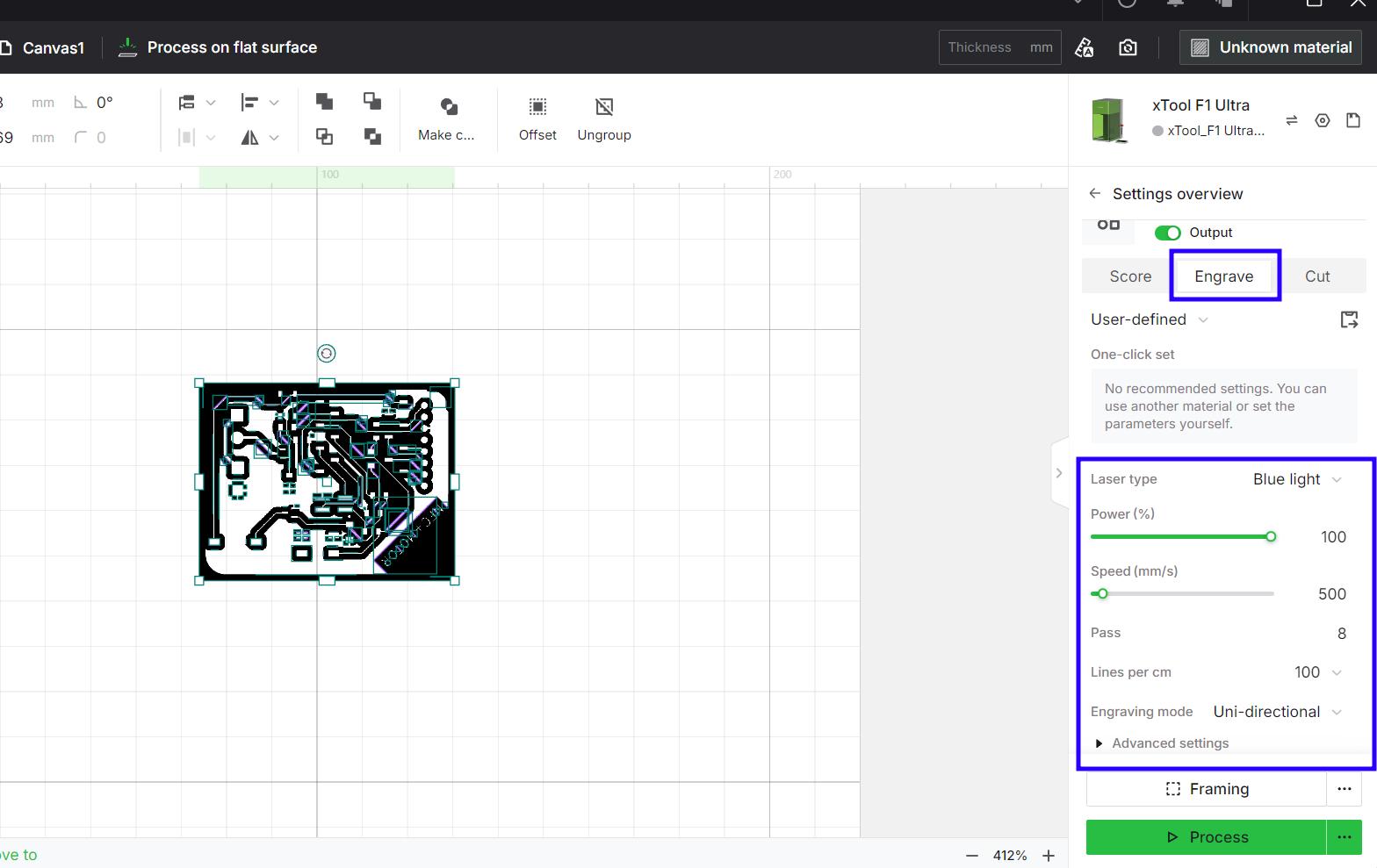
You have to select the Engrave Option and set the parameters as given in the image. After setting the parameters, we have to process this. So click the Process button.
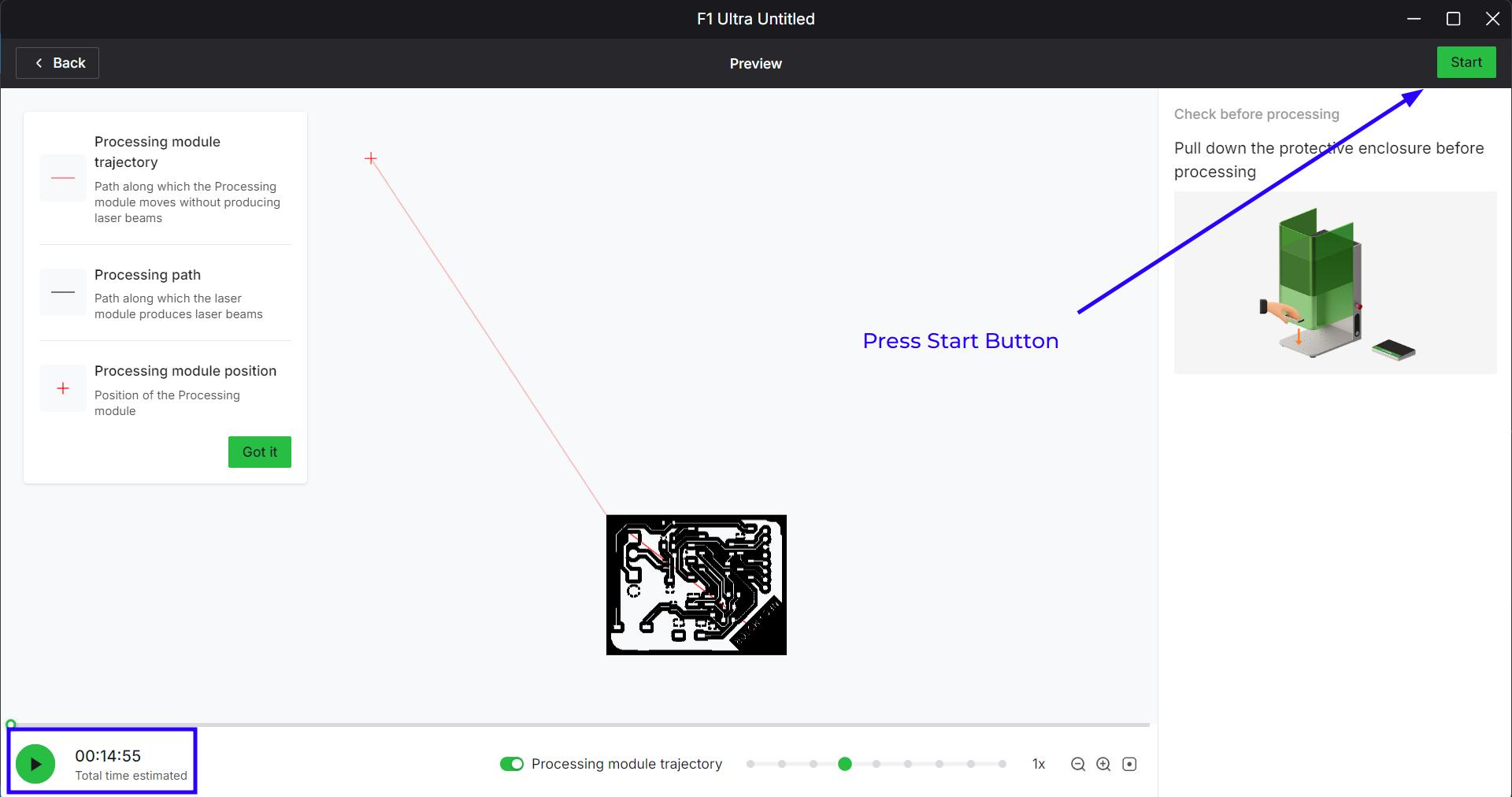
After that press the Start button and then click the button on the XTools F1 Ultra. Please note you have to focus the laser source before running this operation and make sure the lens cap is off.
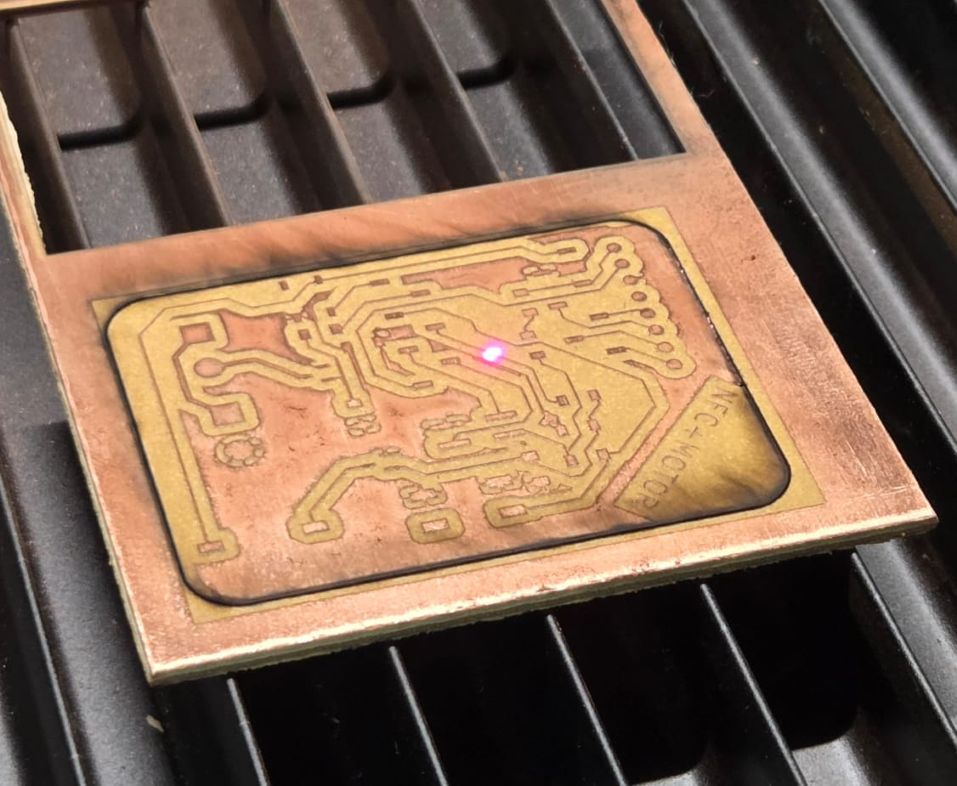
You can see the video of the Xtools engraving the FR4 Board. It is not possible to engrave on the FR1 board as the board would burn eventually in the process. The FR4 is heat resistant as compared to the FR1.
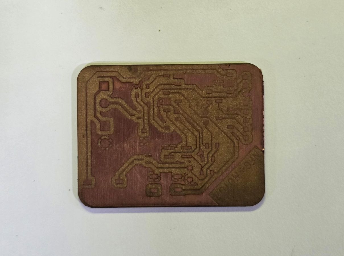
The output looks really nice with really tight tolerances and neat traces as compared to the milling process
Programming
I tested the NFC Module using the example code from the library. You need to install the MFRC522 library by Github to use this code.
The library and the step by step process is mentioned in the documentation
The example is called "ReadNUID" in the MFRC522 library. It will read the NUID of the MIFARE Classic Tag and print it to the Serial Monitor. The code is given below.
#include <SPI.h>
#include <MFRC522.h>

#define SS_PIN D7
#define RST_PIN D6

MFRC522 rfid(SS_PIN, RST_PIN); // Instance of the class

// Init array that will store new NUID
byte nuidPICC[4];

void setup() {
  Serial.begin(9600);
  SPI.begin(); // Init SPI bus
  rfid.PCD_Init(); // Init MFRC522

  Serial.println(F("This code scan the MIFARE Classsic NUID."));
}

void loop() {

  // Reset the loop if no new card present on the sensor/reader. This saves the entire process when idle.
  if ( ! rfid.PICC_IsNewCardPresent())
    return;

  // Verify if the NUID has been readed
  if ( ! rfid.PICC_ReadCardSerial())
    return;

  Serial.print(F("PICC type: "));
  MFRC522::PICC_Type piccType = rfid.PICC_GetType(rfid.uid.sak);
  Serial.println(rfid.PICC_GetTypeName(piccType));

  // Check is the PICC of Classic MIFARE type
  if (piccType != MFRC522::PICC_TYPE_MIFARE_MINI &&
    piccType != MFRC522::PICC_TYPE_MIFARE_1K &&
    piccType != MFRC522::PICC_TYPE_MIFARE_4K) {
    Serial.println(F("Your tag is not of type MIFARE Classic."));
    return;
  }

  if (rfid.uid.uidByte[0] != nuidPICC[0] ||
    rfid.uid.uidByte[1] != nuidPICC[1] ||
    rfid.uid.uidByte[2] != nuidPICC[2] ||
    rfid.uid.uidByte[3] != nuidPICC[3] ) {
    Serial.println(F("A new card has been detected."));

    // Store NUID into nuidPICC array
    for (byte i = 0; i < 4; i++) {
      nuidPICC[i] = rfid.uid.uidByte[i];
    }

    Serial.println(F("The NUID tag is:"));
    Serial.print(F("In hex: "));
    printHex(rfid.uid.uidByte, rfid.uid.size);
    Serial.println();
    Serial.print(F("In dec: "));
    printDec(rfid.uid.uidByte, rfid.uid.size);
    Serial.println();
  }
  else Serial.println(F("Card read previously."));

  // Halt PICC
  rfid.PICC_HaltA();

  // Stop encryption on PCD
  rfid.PCD_StopCrypto1();
}


/**
 * Helper routine to dump a byte array as hex values to Serial.
 */
void printHex(byte *buffer, byte bufferSize) {
  for (byte i = 0; i < bufferSize; i++) {
    Serial.print(buffer[i] < 0x10 ? " 0" : " ");
    Serial.print(buffer[i], HEX);
  }
}

/**
 * Helper routine to dump a byte array as dec values to Serial.
 */
void printDec(byte *buffer, byte bufferSize) {
  for (byte i = 0; i < bufferSize; i++) {
    Serial.print(' ');
    Serial.print(buffer[i], DEC);
  }
}
I wanted to try something basic for my final project progress. So I made the motor run when the NFC ID was detected and to stop the motor when the ID was detected again
#include <SPI.h>
#include <MFRC522.h>

#define SS_PIN D7
#define RST_PIN D6

#define motor D1

MFRC522 rfid(SS_PIN, RST_PIN); // Instance of the class

// Init array that will store new NUID
byte nuidPICC[4];

void setup() {
  pinMode(motor,OUTPUT);
  Serial.begin(9600);
  SPI.begin(); // Init SPI bus
  rfid.PCD_Init(); // Init MFRC522

  Serial.println(F("This code scan the MIFARE Classsic NUID."));
}

void loop() {

  // Reset the loop if no new card present on the sensor/reader. This saves the entire process when idle.
  if ( ! rfid.PICC_IsNewCardPresent())
    return;

  // Verify if the NUID has been readed
  if ( ! rfid.PICC_ReadCardSerial())
    return;

  Serial.print(F("PICC type: "));
  MFRC522::PICC_Type piccType = rfid.PICC_GetType(rfid.uid.sak);
  Serial.println(rfid.PICC_GetTypeName(piccType));

  // Check is the PICC of Classic MIFARE type
  if (piccType != MFRC522::PICC_TYPE_MIFARE_MINI &&
    piccType != MFRC522::PICC_TYPE_MIFARE_1K &&
    piccType != MFRC522::PICC_TYPE_MIFARE_4K) {
    Serial.println(F("Your tag is not of type MIFARE Classic."));
    return;
  }

  if (rfid.uid.uidByte[0] != nuidPICC[0] ||
    rfid.uid.uidByte[1] != nuidPICC[1] ||
    rfid.uid.uidByte[2] != nuidPICC[2] ||
    rfid.uid.uidByte[3] != nuidPICC[3] ) {
    Serial.println(F("A new card has been detected."));
    analogWrite(motor, 30);

    // Store NUID into nuidPICC array
    for (byte i = 0; i < 4; i++) {
      nuidPICC[i] = rfid.uid.uidByte[i];
    }

    Serial.println(F("The NUID tag is:"));
    Serial.print(F("In hex: "));
    printHex(rfid.uid.uidByte, rfid.uid.size);
    Serial.println();
    Serial.print(F("In dec: "));
    printDec(rfid.uid.uidByte, rfid.uid.size);
    Serial.println();
  }
  else
  {
    Serial.println(F("Card read previously."));
    analogWrite(motor, 0);
  }
  // Halt PICC
  rfid.PICC_HaltA();

  // Stop encryption on PCD
  rfid.PCD_StopCrypto1();
}


/**
 * Helper routine to dump a byte array as hex values to Serial.
 */
void printHex(byte *buffer, byte bufferSize) {
  for (byte i = 0; i < bufferSize; i++) {
    Serial.print(buffer[i] < 0x10 ? " 0" : " ");
    Serial.print(buffer[i], HEX);
  }
}

/**
 * Helper routine to dump a byte array as dec values to Serial.
 */
void printDec(byte *buffer, byte bufferSize) {
  for (byte i = 0; i < bufferSize; i++) {
    Serial.print(' ');
    Serial.print(buffer[i], DEC);
  }
}
ESP-NOW Communication
ESP-NOW is a wireless communication protocol defined by Espressif, which enables the direct, quick and low-power control of smart devices, without the need of a router. ESP-NOW can work with Wi-Fi and Bluetooth LE, and supports the ESP8266, ESP32, ESP32-S and ESP32-C series of SoCs. It's widely used in smart-home appliances, remote controlling, sensors, etc.
Getting Started with ESP-NOWTo communicate via ESP-NOW, you need to know the MAC Address of the ESP32 receiver. That's how you know to which device you'll send the data to. Each ESP32 has a unique MAC Address and that's how we identify each board to send data to it using ESP-NOW
/*
Rui Santos & Sara Santos - Random Nerd Tutorials
Complete project details at https://RandomNerdTutorials.com/get-change-esp32-esp8266-mac-address-arduino/
Permission is hereby granted, free of charge, to any person obtaining a copy of this software and associated documentation files.
The above copyright notice and this permission notice shall be included in all copies or substantial portions of the Software.
*/
#include
#include

void readMacAddress(){
uint8_t baseMac[6];
esp_err_t ret = esp_wifi_get_mac(WIFI_IF_STA, baseMac);
if (ret == ESP_OK) {
	Serial.printf("%02x:%02x:%02x:%02x:%02x:%02x\n",
				baseMac[0], baseMac[1], baseMac[2],
				baseMac[3], baseMac[4], baseMac[5]);
} else {
	Serial.println("Failed to read MAC address");
}
}

void setup(){
Serial.begin(115200);

WiFi.mode(WIFI_STA);
WiFi.STA.begin();

Serial.print("[DEFAULT] ESP32 Board MAC Address: ");
readMacAddress();
}

void loop(){

}
For better understanding, we'll call “sender” to ESP32 #1 and “receiver” to ESP32 #2.
Here's what we should include in the sender sketch:
- Initialize ESP-NOW;
- Register a callback function upon sending data - the OnDataSent function will be executed when a message is sent. This can tell us if the message was successfully delivered or not;
- Add a peer device (the receiver). For this, you need to know the receiver MAC address;
- Send a message to the peer device.
On the receiver side, the sketch should include:
- Initialize ESP-NOW;
- Register for a receive callback function (OnDataRecv). This is a function that will be executed when a message is received.
- Inside that callback function, save the message into a variable to execute any task with that information.
typedef struct structName {
	type member1;
	type member2;
	// ...
} typedefName;
Serial.println(status == ESP_NOW_SEND_SUCCESS ? "Delivery Success" : "Delivery Fail");This is a ternery operator,replacing if-else statement. If the status is successful, then print 'Delivery Success' else print 'Delivery Fail'
ESP32 Sender Code
This is the example code provided by RandomNerdTutorials for ESP-NOW communication. You can use this code to send data from one ESP32 to another ESP32. Make sure to replace the MAC address in the code with the MAC address of your receiver ESP32.
/*
	Rui Santos & Sara Santos - Random Nerd Tutorials
	Complete project details at https://RandomNerdTutorials.com/esp-now-esp32-arduino-ide/
	Permission is hereby granted, free of charge, to any person obtaining a copy of this software and associated documentation files.
	The above copyright notice and this permission notice shall be included in all copies or substantial portions of the Software.
  */
  #include <esp_now.h>
  #include <WiFi.h>

  // REPLACE WITH YOUR RECEIVER MAC Address
  uint8_t broadcastAddress[] = {0xFF, 0xFF, 0xFF, 0xFF, 0xFF, 0xFF};

  // Structure example to send data
  // Must match the receiver structure
  typedef struct struct_message {
	char a[32];
	int b;
	float c;
	bool d;
  } struct_message;

  // Create a struct_message called myData
  struct_message myData;

  esp_now_peer_info_t peerInfo;

  // callback when data is sent
  void OnDataSent(const uint8_t *mac_addr, esp_now_send_status_t status) {
	Serial.print("\r\nLast Packet Send Status:\t");
	Serial.println(status == ESP_NOW_SEND_SUCCESS ? "Delivery Success" : "Delivery Fail");
  }

  void setup() {
	// Init Serial Monitor
	Serial.begin(115200);

	// Set device as a Wi-Fi Station
	WiFi.mode(WIFI_STA);

	// Init ESP-NOW
	if (esp_now_init() != ESP_OK) {
	  Serial.println("Error initializing ESP-NOW");
	  return;
	}

	// Once ESPNow is successfully Init, we will register for Send CB to
	// get the status of Trasnmitted packet
	esp_now_register_send_cb(OnDataSent);

	// Register peer
	memcpy(peerInfo.peer_addr, broadcastAddress, 6);
	peerInfo.channel = 0;
	peerInfo.encrypt = false;

	// Add peer
	if (esp_now_add_peer(&peerInfo) != ESP_OK){
	  Serial.println("Failed to add peer");
	  return;
	}
  }

  void loop() {
	// Set values to send
	strcpy(myData.a, "THIS IS A CHAR");
	myData.b = random(1,20);
	myData.c = 1.2;
	myData.d = false;

	// Send message via ESP-NOW
	esp_err_t result = esp_now_send(broadcastAddress, (uint8_t *) &myData, sizeof(myData));

	if (result == ESP_OK) {
	  Serial.println("Sent with success");
	}
	else {
	  Serial.println("Error sending the data");
	}
	delay(2000);
  }
ESP32 receiver Code
This is the example code provided by RandomNerdTutorials for ESP-NOW communication. You can use this code to receive data from another ESP32. Make sure to upload this code to the receiver ESP32. The major point is to make sure that the structure of the data being sent matches the structure of the data being received.
	/*
  Rui Santos & Sara Santos - Random Nerd Tutorials
  Complete project details at https://RandomNerdTutorials.com/esp-now-esp32-arduino-ide/
  Permission is hereby granted, free of charge, to any person obtaining a copy of this software and associated documentation files.
  The above copyright notice and this permission notice shall be included in all copies or substantial portions of the Software.
*/

#include <esp_now.h>
#include <WiFi.h>

// Structure example to receive data
// Must match the sender structure
typedef struct struct_message {
    char a[32];
    int b;
    float c;
    bool d;
} struct_message;

// Create a struct_message called myData
struct_message myData;

// callback function that will be executed when data is received
void OnDataRecv(const uint8_t * mac, const uint8_t *incomingData, int len) {
  memcpy(&myData, incomingData, sizeof(myData));
  Serial.print("Bytes received: ");
  Serial.println(len);
  Serial.print("Char: ");
  Serial.println(myData.a);
  Serial.print("Int: ");
  Serial.println(myData.b);
  Serial.print("Float: ");
  Serial.println(myData.c);
  Serial.print("Bool: ");
  Serial.println(myData.d);
  Serial.println();
}

void setup() {
  // Initialize Serial Monitor
  Serial.begin(115200);

  // Set device as a Wi-Fi Station
  WiFi.mode(WIFI_STA);

  // Init ESP-NOW
  if (esp_now_init() != ESP_OK) {
    Serial.println("Error initializing ESP-NOW");
    return;
  }

  // Once ESPNow is successfully Init, we will register for recv CB to
  // get recv packer info
  esp_now_register_recv_cb(esp_now_recv_cb_t(OnDataRecv));
}

void loop() {

}
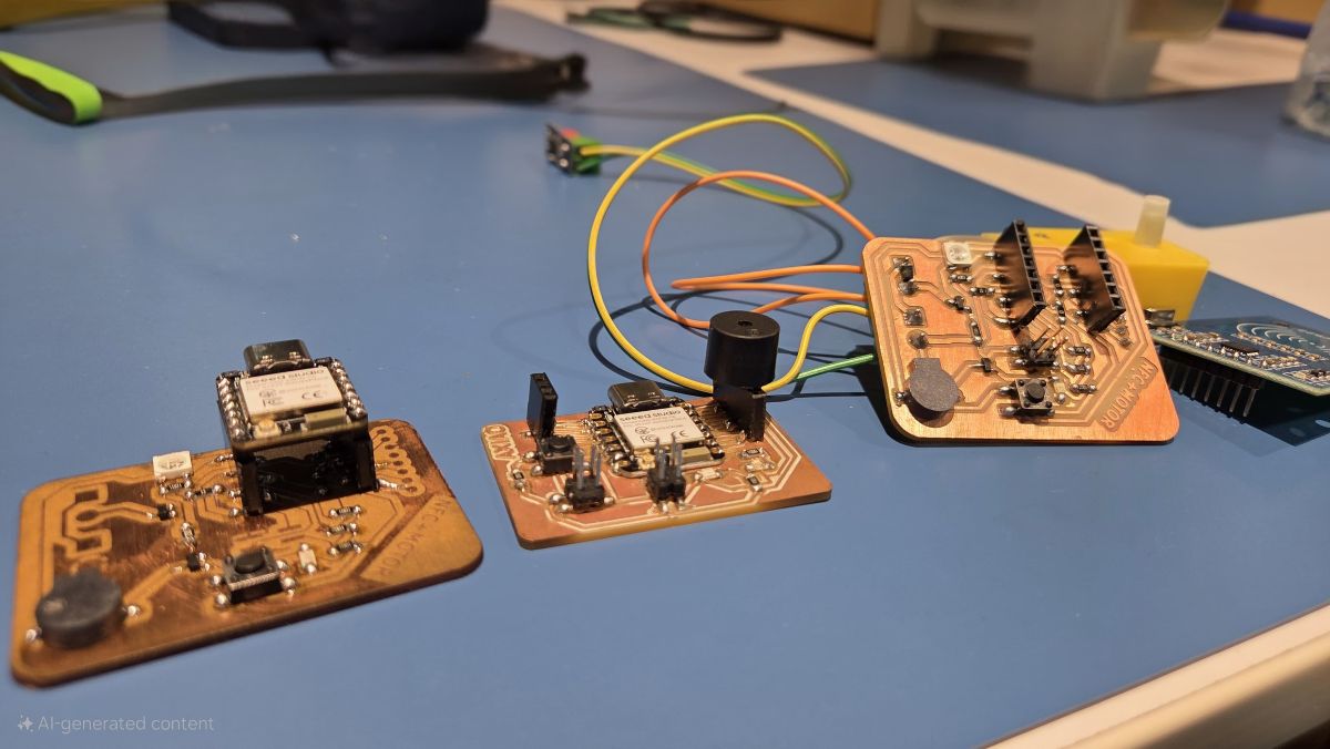
I want to use ESP-NOW to communicate through the network of boards. I'll be using the NFC+Motor Board for this, it has a speaker, LED and WS2812B RGB LED. I'll be using the two boards that I made this week for this network.
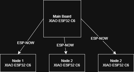
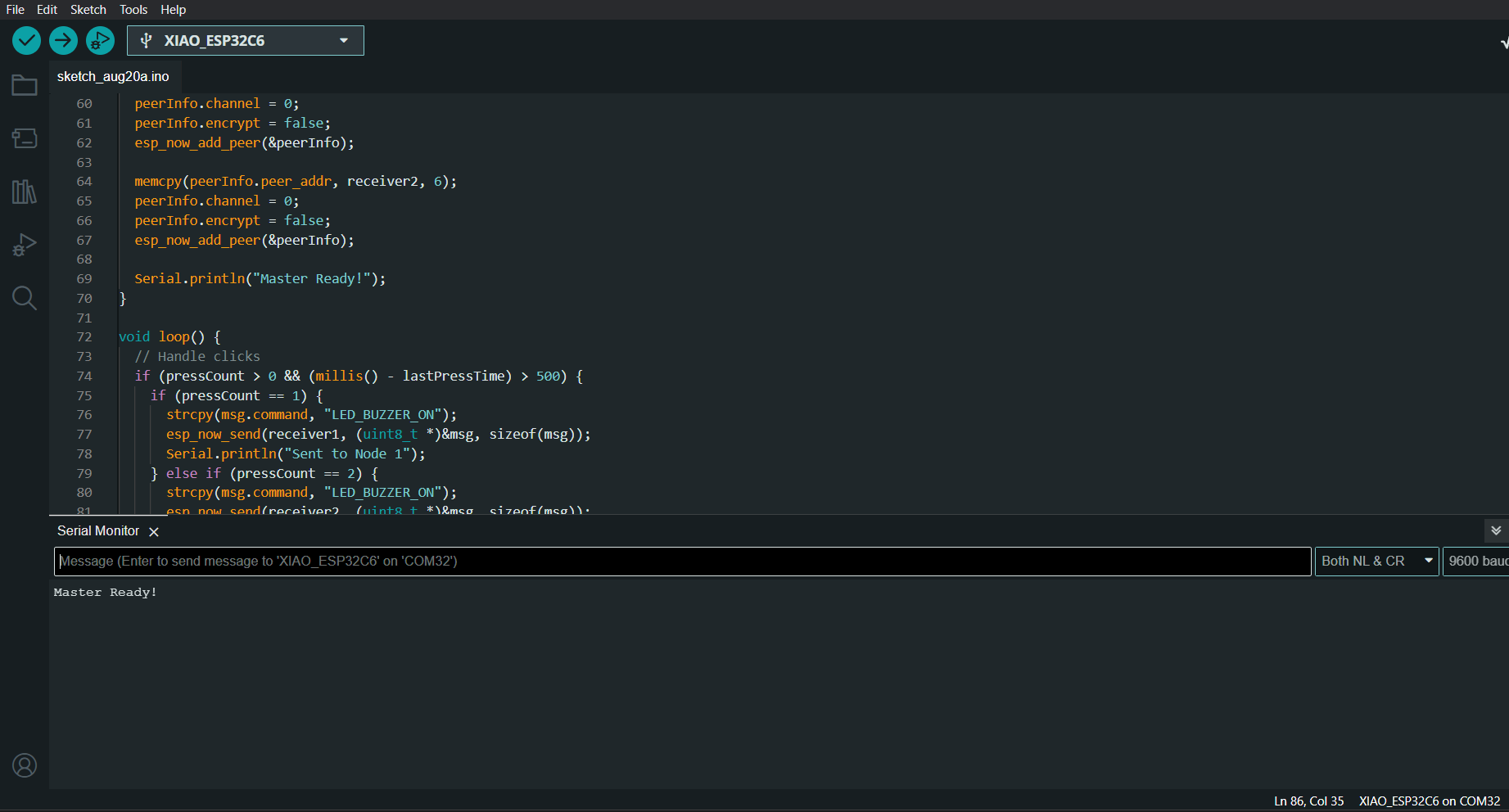
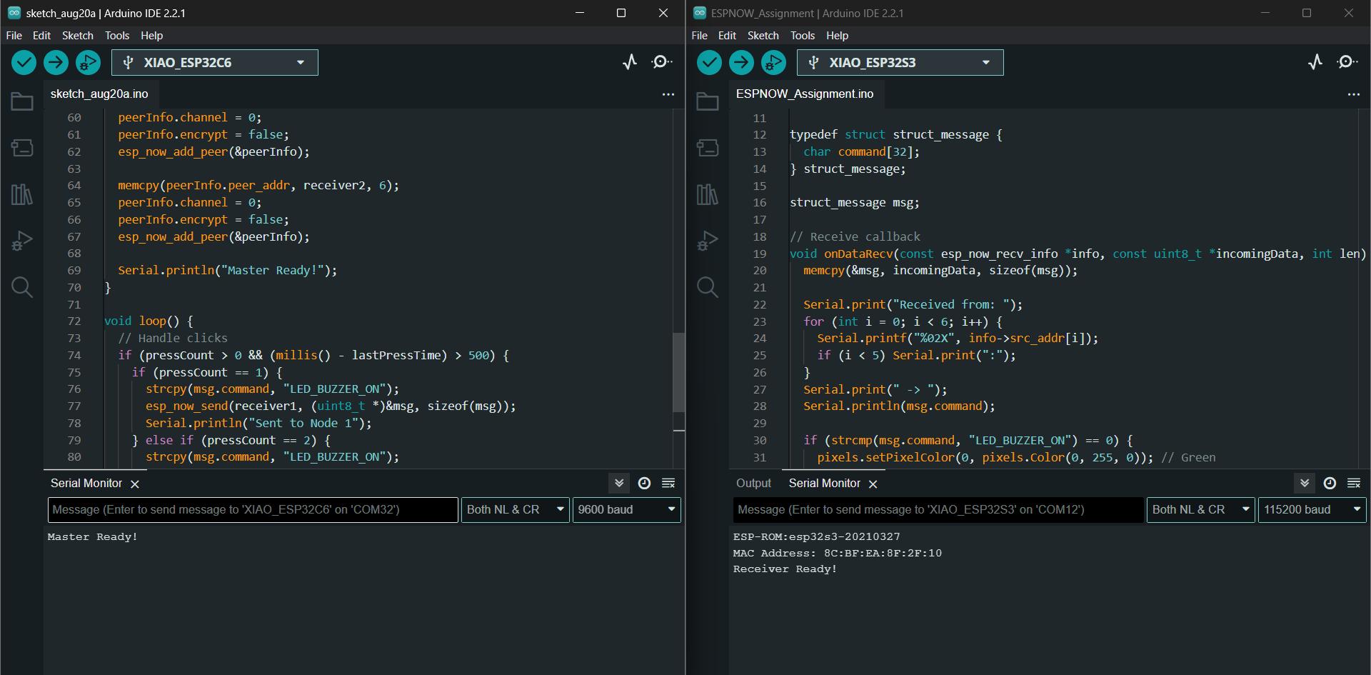
Master Board
The master board can selectively send messages to the nodes and control them. The reciever MAC Addresses need to be initialised here and the ESP-NOW communication needs to be
#include <esp_now.h>
#include <WiFi.h>

// Replace with your receivers' MAC addresses
uint8_t receiver1[] = {0x8C, 0xBF, 0xEA, 0x8F, 0x2F, 0x10}; //8C:BF:EA:8F:2F:10
// uint8_t receiver2[] = {0x8C, 0xBF, 0xEA, 0x65, 0x43, 0x21};

#define BUTTON_PIN 2   // GPIO2 for push button

typedef struct struct_message {
  char command[32];
} struct_message;

struct_message msg;

// Button handling
unsigned long lastPressTime = 0;
int pressCount = 0;

// ISR for button
void IRAM_ATTR buttonISR() {
  unsigned long now = millis();
  if (now - lastPressTime > 200) {  // debounce
    pressCount++;
    lastPressTime = now;
  }
}

// Send status callback
void onDataSent(const uint8_t *mac_addr, esp_now_send_status_t status) {
  Serial.print("Delivery to ");
  for (int i = 0; i < 6; i++) {
    Serial.printf("%02X", mac_addr[i]);
    if (i < 5) Serial.print(":");
  }
  Serial.print(" -> ");
  Serial.println(status == ESP_NOW_SEND_SUCCESS ? "Success" : "Fail");
}

void setup() {
  Serial.begin(115200);
  WiFi.mode(WIFI_STA);

  pinMode(BUTTON_PIN, INPUT_PULLUP);
  attachInterrupt(digitalPinToInterrupt(BUTTON_PIN), buttonISR, FALLING);

  if (esp_now_init() != ESP_OK) {
    Serial.println("Error initializing ESP-NOW");
    return;
  }

  // Register send callback
  esp_now_register_send_cb(onDataSent);

  // Add peers
  esp_now_peer_info_t peerInfo;
  memset(&peerInfo, 0, sizeof(peerInfo));

  memcpy(peerInfo.peer_addr, receiver1, 6);
  peerInfo.channel = 0;
  peerInfo.encrypt = false;
  esp_now_add_peer(&peerInfo);

  memcpy(peerInfo.peer_addr, receiver2, 6);
  peerInfo.channel = 0;
  peerInfo.encrypt = false;
  esp_now_add_peer(&peerInfo);

  Serial.println("Master Ready!");
}

void loop() {
  // Handle clicks
  if (pressCount > 0 && (millis() - lastPressTime) > 500) {
    if (pressCount == 1) {
      strcpy(msg.command, "LED_BUZZER_ON");
      esp_now_send(receiver1, (uint8_t *)&msg, sizeof(msg));
      Serial.println("Sent to Node 1");
    } else if (pressCount == 2) {
      strcpy(msg.command, "LED_BUZZER_ON");
      esp_now_send(receiver2, (uint8_t *)&msg, sizeof(msg));
      Serial.println("Sent to Node 2");
    }
    else if(pressCount == 3) {
      strcpy(msg.command, "ALL_OFF");
      esp_now_send(receiver1, (uint8_t *)&msg, sizeof(msg));
      Serial.println("Turn OFF Message sent");
    }
    pressCount = 0;
  }

}
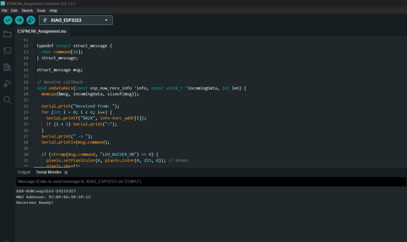
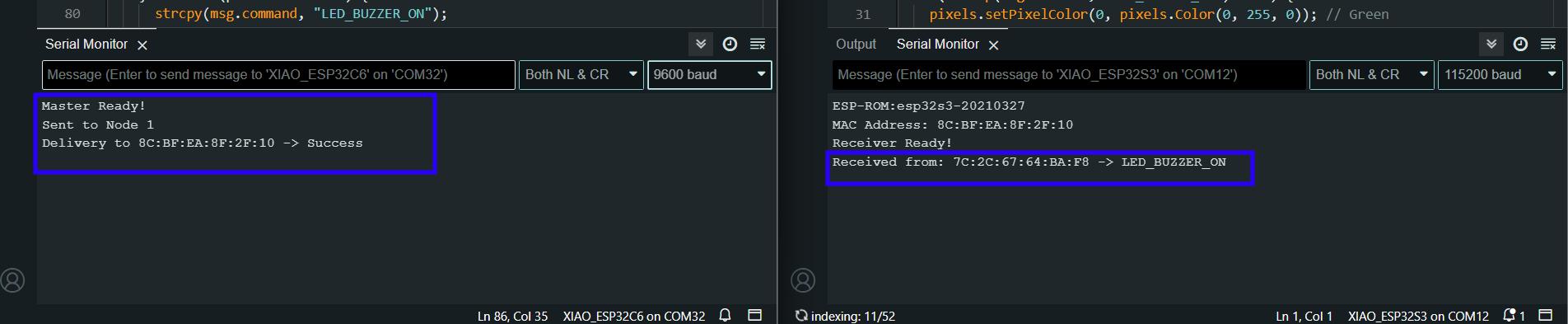
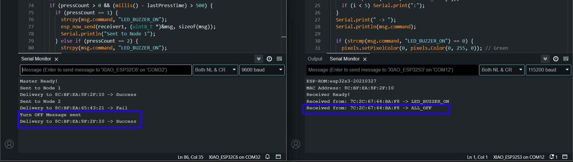
Reciever Nodes
The reciever nodes in the network need to recieve the ESP-NOW message and respond accordingly. The master node can selectively send messages to respective nodes. The nodes recieve the LED_BUZZER_ON message and turn the oboard WS2812B LED green and a simple tone on the speaker.
#include <esp_now.h>
#include <WiFi.h>
#include <esp_wifi.h>
#include <Adafruit_NeoPixel.h>

#define BUZZER_PIN D3   // GPIO3
#define LED_PIN    D0   // GPIO0
#define NUMPIXELS  1

Adafruit_NeoPixel pixels(NUMPIXELS, LED_PIN, NEO_GRB + NEO_KHZ800);

typedef struct struct_message {
  char command[32];
} struct_message;

struct_message msg;

// Receive callback
void onDataRecv(const esp_now_recv_info *info, const uint8_t *incomingData, int len) {
  memcpy(&msg, incomingData, sizeof(msg));

  Serial.print("Received from: ");
  for (int i = 0; i < 6; i++) {
    Serial.printf("%02X", info->src_addr[i]);
    if (i < 5) Serial.print(":");
  }
  Serial.print(" -> ");
  Serial.println(msg.command);

  if (strcmp(msg.command, "LED_BUZZER_ON") == 0) {
    pixels.setPixelColor(0, pixels.Color(0, 255, 0)); // Green
    pixels.show();
    digitalWrite(BUZZER_PIN, HIGH);
    delay(300);
    digitalWrite(BUZZER_PIN, LOW);
  } else if (strcmp(msg.command, "ALL_OFF") == 0) {
    pixels.clear();
    pixels.show();
    digitalWrite(BUZZER_PIN, LOW);
  }
}

void readMacAddress() {
  uint8_t baseMac[6];
  esp_err_t ret = esp_wifi_get_mac(WIFI_IF_STA, baseMac);
  if (ret == ESP_OK) {
    Serial.printf("MAC Address: %02X:%02X:%02X:%02X:%02X:%02X\n",
                  baseMac[0], baseMac[1], baseMac[2],
                  baseMac[3], baseMac[4], baseMac[5]);
  } else {
    Serial.println("Failed to read MAC address");
  }
}

void setup() {
  Serial.begin(115200);

  pinMode(BUZZER_PIN, OUTPUT);
  digitalWrite(BUZZER_PIN, LOW);

  pixels.begin();
  pixels.clear();
  pixels.show();

  WiFi.mode(WIFI_STA);

  if (esp_now_init() != ESP_OK) {
    Serial.println("Error initializing ESP-NOW");
    return;
  }

  esp_now_register_recv_cb(onDataRecv);

  readMacAddress();
  Serial.println("Receiver Ready!");
}

void loop() {
  // all handled in callback
}
MQTT Communication with Rico
Using the board that I designed in this week, I communicated with Rico Kanthatham at Skylab Workshop. I used Message Query Telemetry Transportation (MQTT) for this purpose. I have documented about MQTT and the whole process in the week 14 Interface and Application assignment. You can refer to the same.
This is the video of Rico sending and recieving the morse code to our lab
Design Files
You can download my design files from below
NFC+Motor XIAO ESP32C6 Board
Milling Files
KiCad Files
Laser Files
Xtools Processing Files