This week, I focused on designing, fabricating, and assembling a custom PCB featuring a SAMD21 MCU, a rotary encoder, and a capacitive touch slider. I also learned about the functionality and integration of these input devices.
Hero Shot
Learning Objectives
Demonstrate workflows used in sensing something with input device(s) and MCU board
Assignments
Group Assignments
probe an input device's analog levels and digital signals
In this week, I decided to work with Capacitive Touch Slider and Rotary Encoder. I wanted to explore the capabilities of capacitive touch sensors and how they can be integrated into a microcontroller board.
Step Response/ Capacitive Touch
Capacitive touch sensors are devices that detect touch or proximity by measuring changes in capacitance. They work by using a conductive pad that forms a capacitor with the human body. When a finger approaches the pad, it alters the capacitance, which can be measured to determine if a touch has occurred.
I refered to some previous works of students who used capacitive touch and SAMD21
I refered to these documentations and studied about different types of Capacitive touch sensors and how they work. I studied about how these sensors work, and then Saheen told me that the board I chose, already has QTouch capibilities
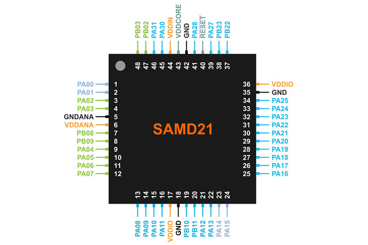
I studied about how QTouch works on SAMD21 E17, the SAMD21 has specific pins called PTC pins to control
The QTouch® Peripheral Touch Controller (PTC) offers built-in hardware for capacitive touch measurement on sensors that function as buttons, sliders, and wheels. The PTC has been designed to perform capacitive touch acquisition on sensors independently from the CPU, resulting in low CPU utilization and reduced power consumption.
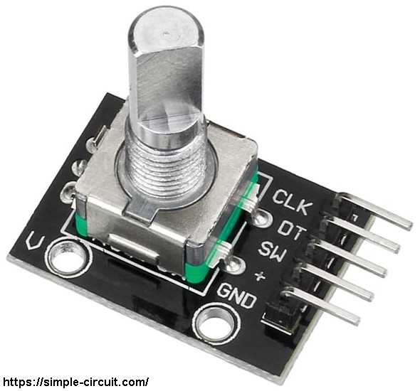
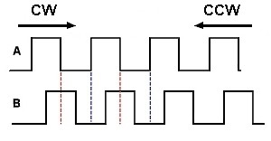
Since the normal state of pin A (CLK) and pin B (DT) are logic high we've to detect falling (transition from high to low) of one of them, here pin A is used to detect the movement of the rotary encoder in both directions (falling of pin A signal). Direction of rotation can be detected by knowing the status of pin B, if pin B is logic high this means the direction of rotation is clockwise (CW), and if pin B is logic low this means the direction of rotation is counter clockwise (CCW).
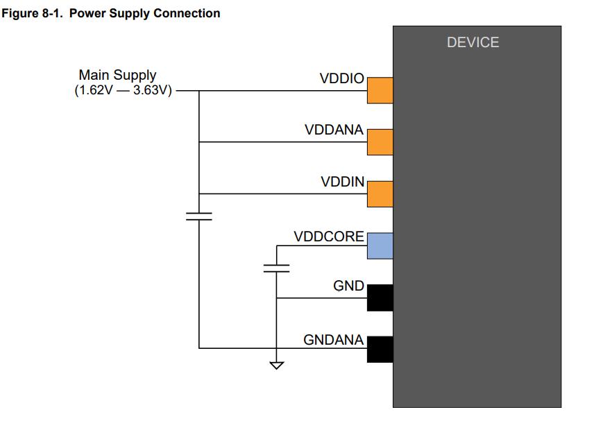
The device has several different power supply pins:
VDDIO: Powers I/O lines, OSC8M and XOSC. Voltage is 1.62V to 3.63V.
VDDIN: Powers I/O lines and the internal regulator. Voltage is 1.62V to 3.63V.
VDDANA: Powers I/O lines and the ADC, AC, DAC, PTC, OSCULP32K, OSC32K, XOSC32K. Voltage is 1.62V
to 3.63V.
VDDCORE: Internal regulated voltage output. Powers the core, memories, peripherals, FDPLL96M, and
DFLL48M. Voltage is 1.2V.
The same voltage must be applied to both VDDIN, VDDIO and VDDANA. This common voltage is referred to as VDD
in the datasheet.
The ground pins, GND, are common to VDDCORE, VDDIO and VDDIN. The ground pin for VDDANA is GNDANA
SAMD21 Recommended Power connection
I decided to try something which involved buttons, sliders and enncoders for my final project - Symphoni The Record Player. But after seeing the class, I was amused by the capacitive touch and its capabilities. Therefore I decided my sensors for the week - Capacitive Touch Slider and Rotary Encoder.
I decided to use a 5 Capacitive Pad slider with a rotary encoder. And I decided to explore a new microcontroller - SAMD21 E17A.
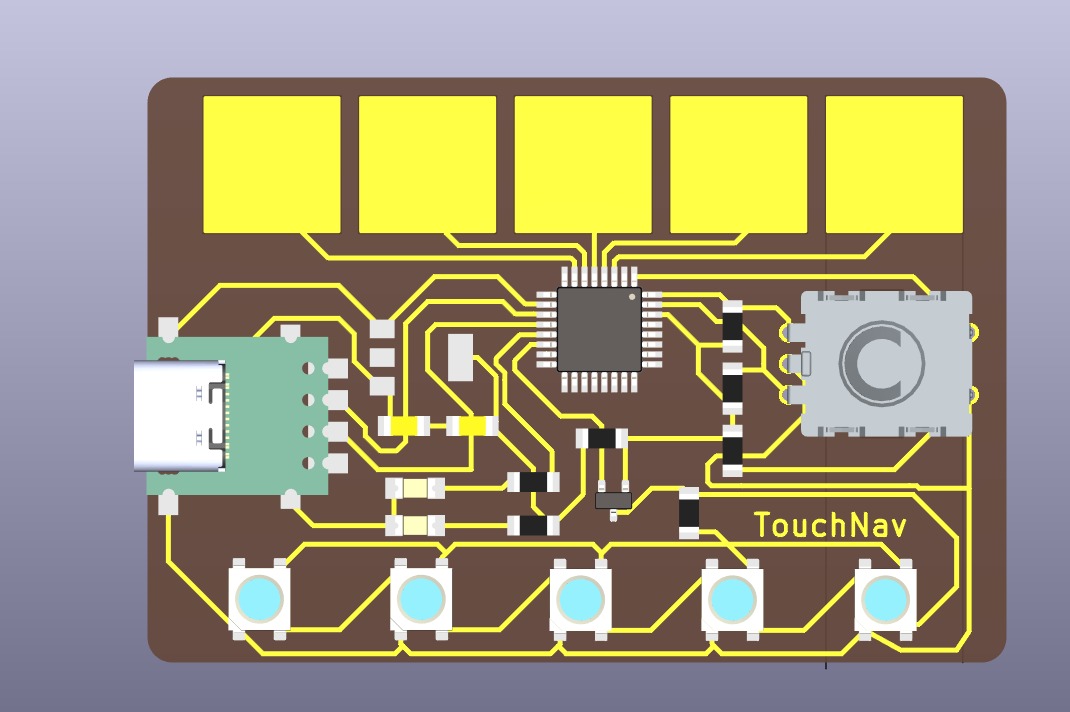
TouchNav SAMD21
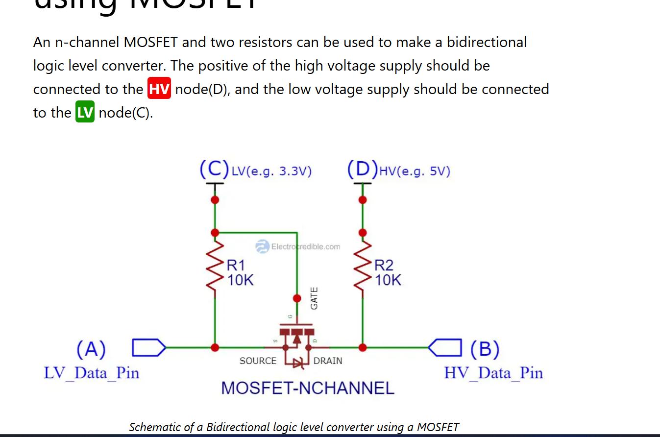
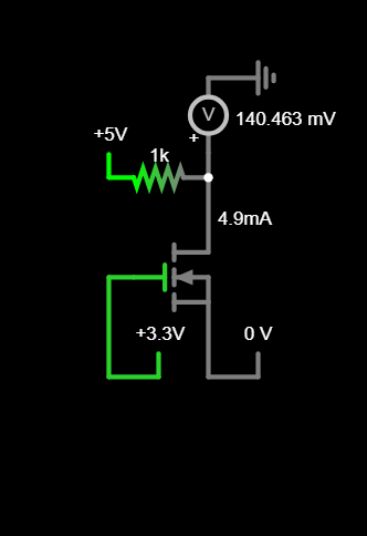
The WS2812B uses 5V but my MCU uses 3.3 V logic level, therefore I needed the 5V output. So I had to make a logic level shifter. So I learned more about Logic Level Shifter.
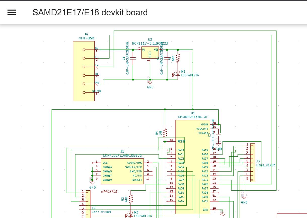
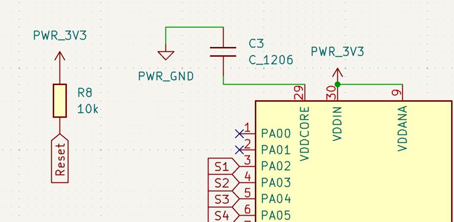
The SAMD21 E17 requires some mandatory connections for its basic functionality. The connections are mainly for the power connections and Serial Debug Wire Pins . The below shown image shows the connections in the schematic Design.
VDD Connections
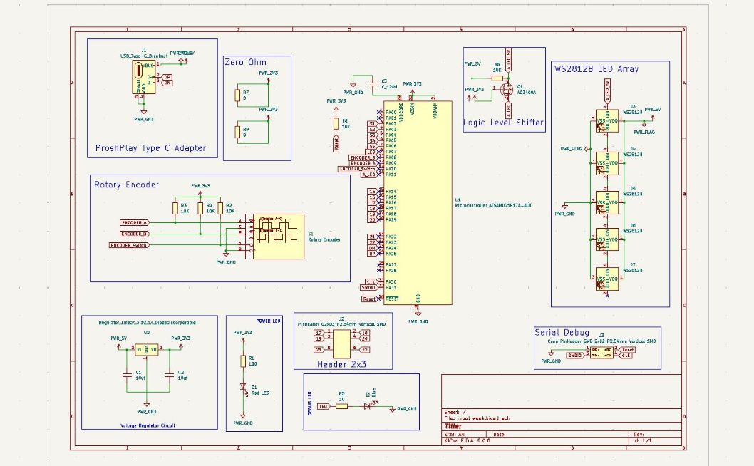
Some newer elements in the schematic are ProshPlay Type C Breakout Board and Rotary Encoder Connection. I have also labelled the capacitive touch pad pins as S1,S2,S3,S4,S5,
The below image shows the full schematic Design of the board.
Final Schematic
You can refer to the below Schematic PDF for clearer viewing.
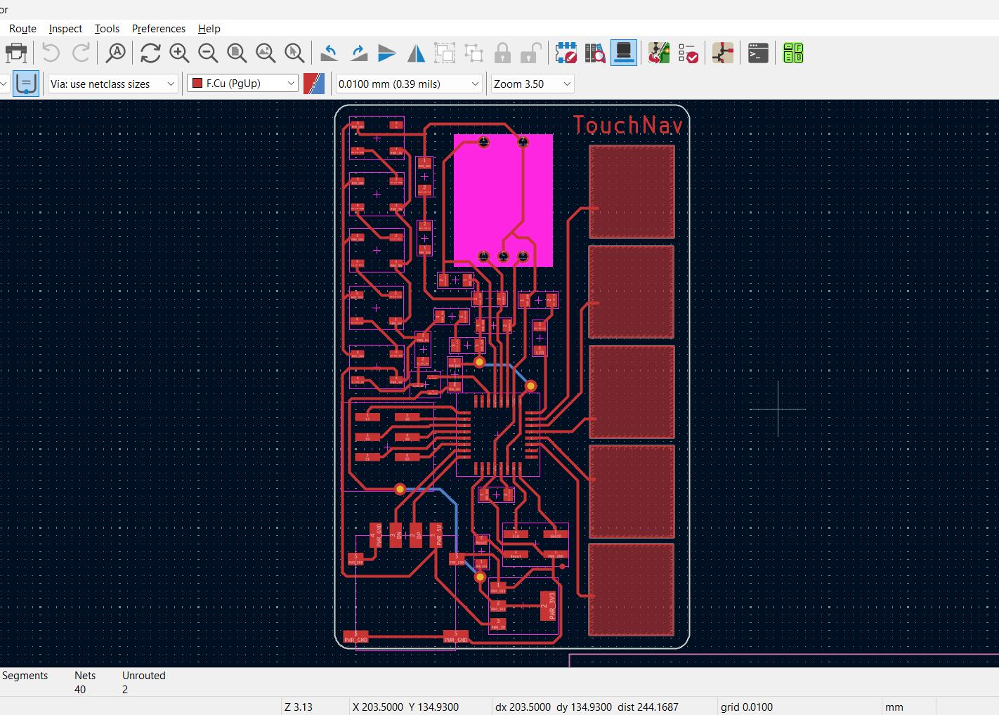
After the schematic design, I started designing the PCB in KiCad/p>
TouchNav PCB
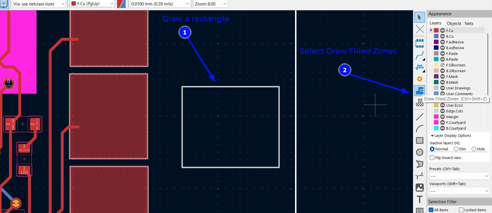
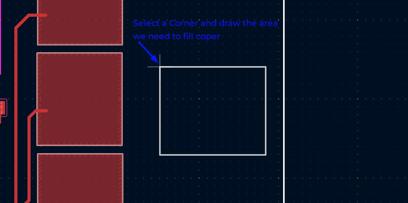
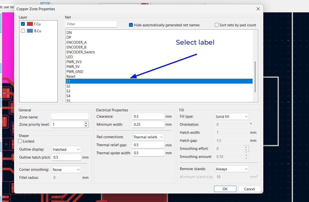
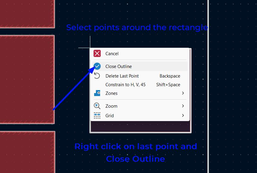
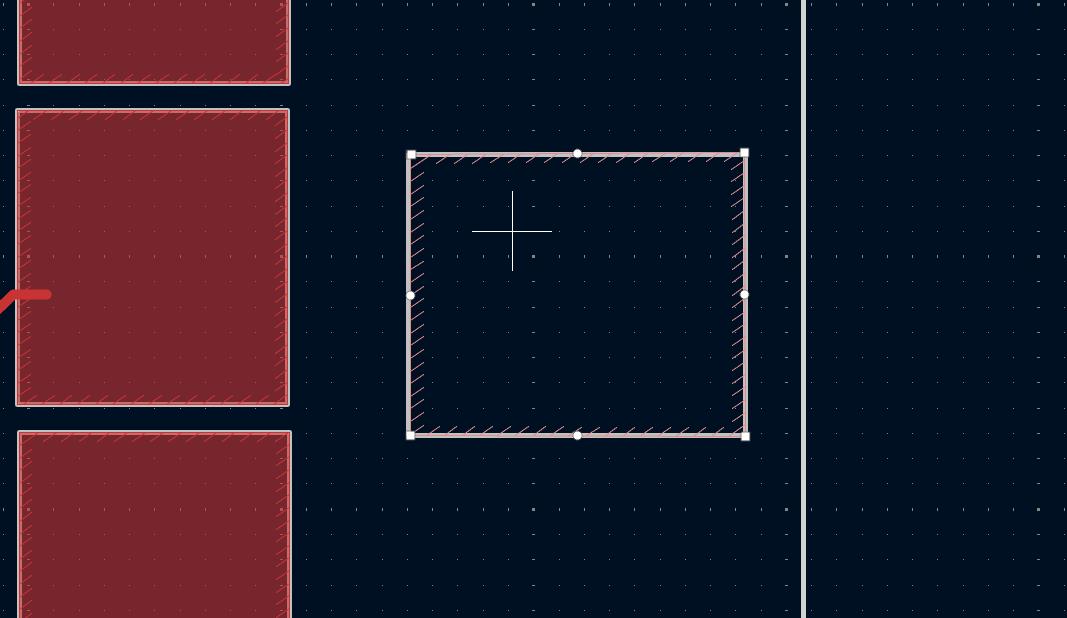
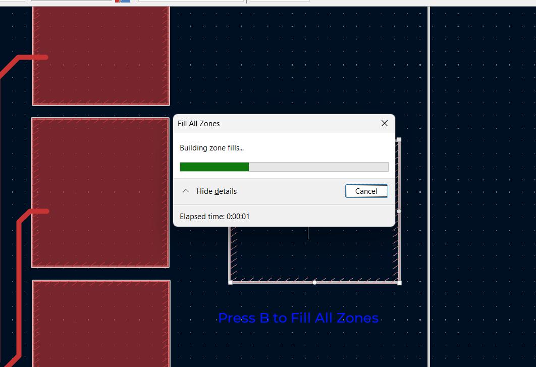
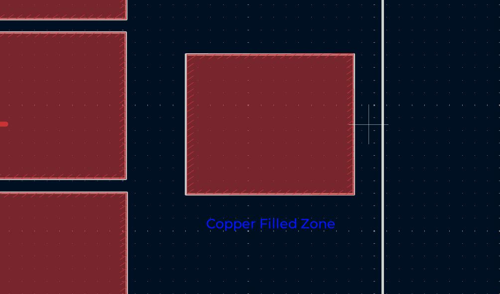
For making the copper pads for capacitive touch sensors, I used the copper fill feature available in KiCad. I allocatted a label for every touch pad and gave it names S1, S2, S3, S4 and S5. Then I assigned every rectangle with each label and copper filled it.
The below images how a step by step process of adding a copper fill zone in KiCad.
Adding Rectangular PadSelect Draw Filled Zone and selcect a cornerSelect LabelSelect Bounding Area and Close OutlineAfter Drawing Copper ZoneFill All ZonesCopper Zone
I used the similiar technique for the rest of my touch pads and connected them to the respective pins.
Production and Assembly
After routing the PCB in KiCad, I milled the PCB using the Roland MDX Milling Machine. After inspection I realised that the traces at some points were very thin and uneven at certain places. The cause of this was not complying to the design constraints and rules of our machining process. I missed the step and got this result, but still the output was decent ignoring some thin traces.
Design Rules Failure
The microscope inscpection shows the thin traces at certain parts of the PCB
Design Rules FailureAssembly
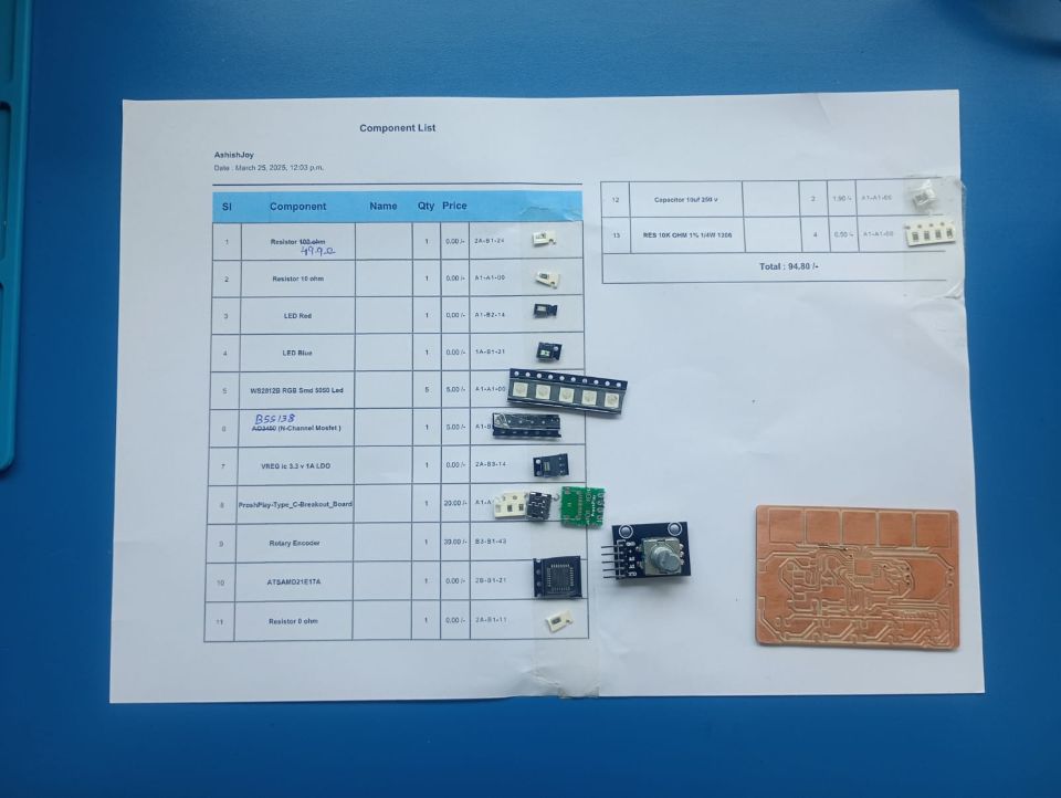
After preparing the BOM and requesting the components from the fablab inventory using Fab Stash. Below are the components before soldering.
Components List
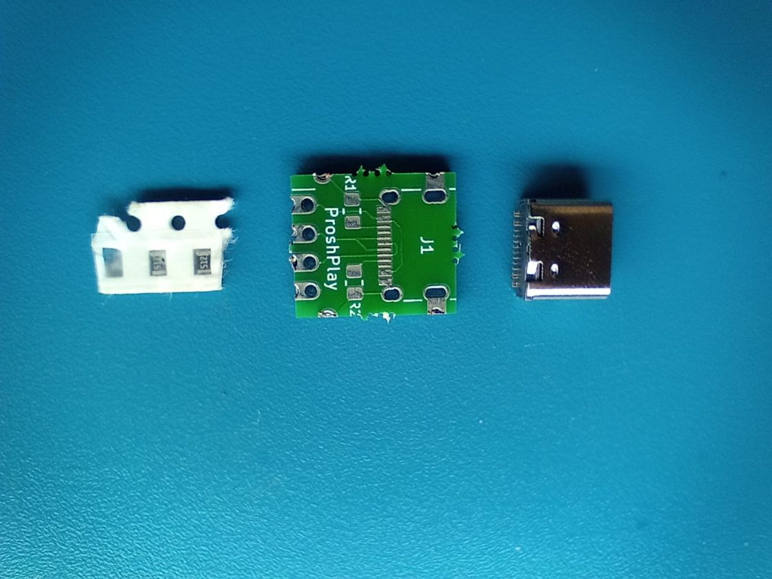
As the SAMD21 board is USB compatible, I decided to use the ProshPlay Module to program the board. The below are the componenets of the Proshplay Module:
USB C receptecale, ProshPlay PCB, 2 Resistors
The Proshplay Breakout Board is designed and developed by our instructorSaheen PalayiYou can refer to the documentation of ProshPlay Adapter for further information.
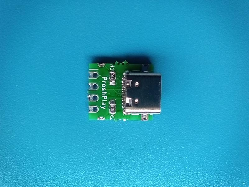
I had never soldered a board with such fine spacing, I tieed to solder the USB C receptecale on the PCB but it was difficult to not solder the legs together somehow. Saheen helped me to solder the PCB. The below picture shows the breakout board assembled.
ProshPlay Assembled
After assembling the Proshplay Breakout board, I soldered it to my TouchNav PCB along with the other components.
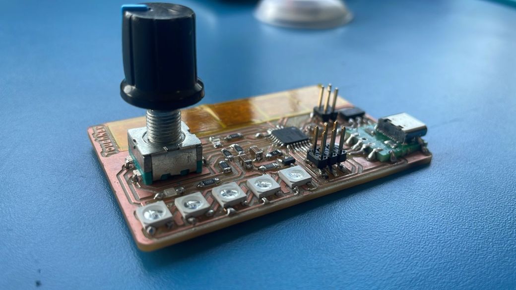
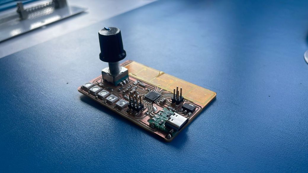
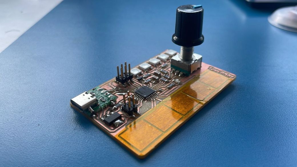
Below are some hero shots of my PCB - TouchNav. I named the board TouchNav because it features a touch slider and a rotary encoder to navigate.
Hero ShotsHero ShotsHero Shots
Programing TouchNav(SAMD21 Board)
The TouchNav Board has a SAMD21 E17 at its core, so to program the SAMD21 we need to add the bootloader to the board. To flash the bootloader initially, we need the Serial Debug Pins. Only after that can we program the board using USB.
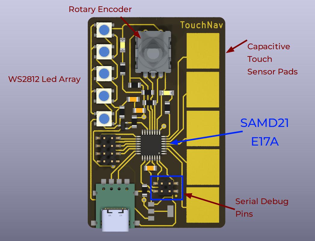
TouchNav SAMD21 Components
The above image shows the components of the board: Capacitive Touch Sensor Pads, Rotary Encoder, WS2812B LED Array, Serial Debug Pins, USB C and SAMD21 E17
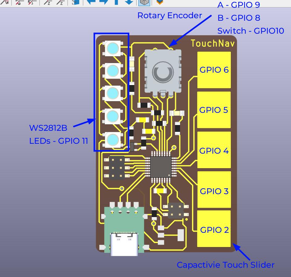
TouchNav Pinout
The pinouts are as follows:
LED - 7
WS2812B - 11
Rotary Encoder - A - 9, B - 8, Switch - 10
Capacitive Touch Slider - GPIO 2,3,4,5,6
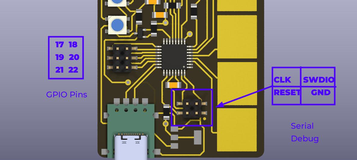
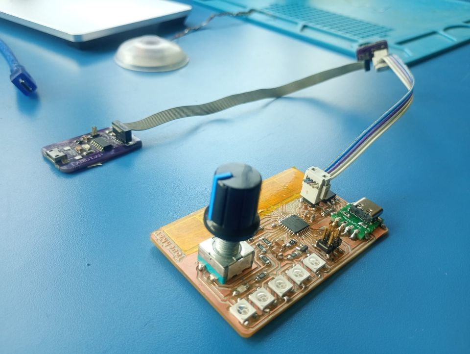
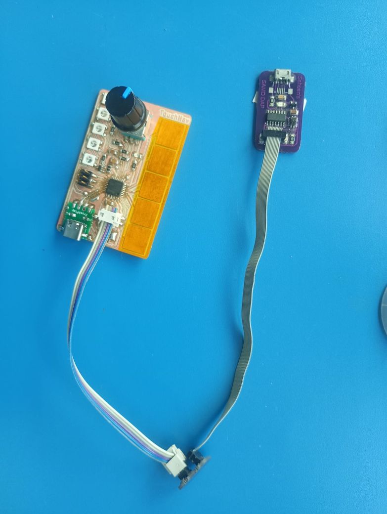
TouchNav Serial Debug Pins
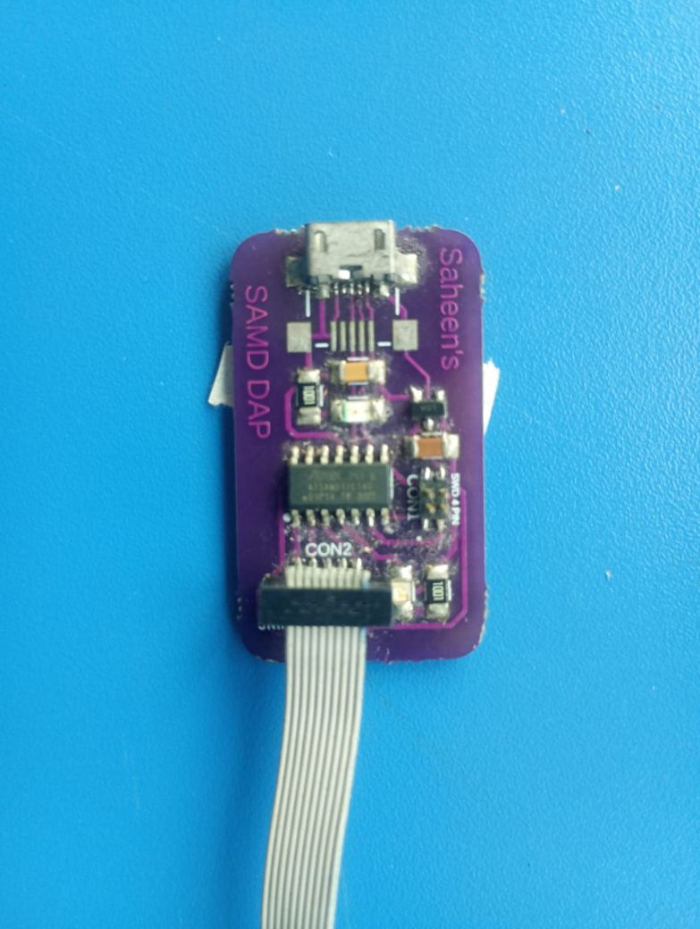
This is the connection for Bootloader Programming, using the SAMD DAP programmer made by Saheen.
Bootloader ProgrammingSaheen's SAMD Programmer
Programming SetupSerial Debug Connection
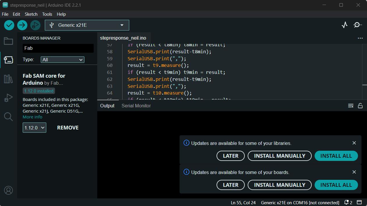
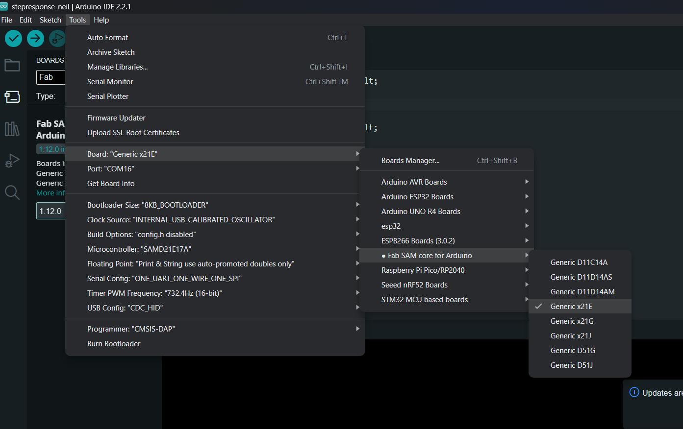
Adding the FAB SAMD Board to Arduino
To program the SAMD21 Board using Arduino IDE, we need to add the FAB SAMD Board to the Board Manager
We need to burn the bootloader first using Saheens's SAMD DAP programmer. Only then can I program using the USB C Cable. This step is only needed initially.
My programming process was to initially test the functionality of all my connected devices such as the LED, rotary encoder and the capacitive touch pads. After testing the boards I wanted to use the board as a HID Device to control Media Playback.
Blink
After burning the bootloader the first step was to test the builtin example 'Blink'
// the setup function runs once when you press reset or power the board
void setup() {
  // initialize builtin LED at pin 7 as an output.
  pinMode(7, OUTPUT);
}

// the loop function runs over and over again forever
void loop() {
  digitalWrite(7, HIGH);  // turn the LED on (HIGH is the voltage level)
  delay(1000);                      // wait for a second
  digitalWrite(7, LOW);   // turn the LED off by making the voltage LOW
  delay(1000);                      // wait for a second
}
SAMD21 Serial Demo
The next test was serial communication. After research, I realised the usual arduino command Serial.print doesn't work for the SAMD21, therefore we have to use SerialUSB.print. The below code is taken from Embedded Programming class. SAMD21 Echo Code
//
// hello.D21E.echo.ino
//
// ATSAMD21E USB echo hello-world
//
// Neil Gershenfeld 12/24/19
//
// This work may be reproduced, modified, distributed,
// performed, and displayed for any purpose, but must
// acknowledge this project. Copyright is retained and
// must be preserved. The work is provided as is; no
// warranty is provided, and users accept all liability.
//

void setup() {
  SerialUSB.begin(115200);
}

#define max_buffer 25

void loop() {
  static char chr;
  static char buffer[max_buffer] = { 0 };
  static int index;
  if (SerialUSB.available()) {
    chr = SerialUSB.read();
    SerialUSB.print("hello.D21E.echo: you typed \"");
    buffer[index++] = chr;
    if (index == (max_buffer - 1))
      index = 0;
    SerialUSB.print(buffer);
    SerialUSB.println("\"");
  }
}
Rotary Encoder
// Rotary Encoder Inputs
#define CLK 9
#define DT 8
#define SW 10

int counter = 0;
int currentStateCLK;
int lastStateCLK;
String currentDir ="";
unsigned long lastButtonPress = 0;

void setup() {

	// Set encoder pins as inputs
	pinMode(CLK,INPUT);
	pinMode(DT,INPUT);
	pinMode(SW, INPUT_PULLUP);

	// Setup Serial Monitor
	SerialUSB.begin(9600);

	// Read the initial state of CLK
	lastStateCLK = digitalRead(CLK);
}

void loop() {

	// Read the current state of CLK
	currentStateCLK = digitalRead(CLK);

	// If last and current state of CLK are different, then pulse occurred
	// React to only 1 state change to avoid double count
	if (currentStateCLK != lastStateCLK  && currentStateCLK == 1){

		// If the DT state is different than the CLK state then
		// the encoder is rotating CCW so decrement
		if (digitalRead(DT) != currentStateCLK) {
			counter ++;
			currentDir ="CW";
		} else {
			// Encoder is rotating CW so increment
			counter --;
			currentDir ="CCW";
		}

		SerialUSB.print("Direction: ");
		SerialUSB.print(currentDir);
		SerialUSB.print(" | Counter: ");
		SerialUSB.println(counter);
	}

	// Remember last CLK state
	lastStateCLK = currentStateCLK;

	// Read the button state
	int btnState = digitalRead(SW);

	//If we detect LOW signal, button is pressed
	if (btnState == LOW) {
		//if 50ms have passed since last LOW pulse, it means that the
		//button has been pressed, released and pressed again
		if (millis() - lastButtonPress > 50) {
			SerialUSB.println("Button pressed!");
		}

		// Remember last button press event
		lastButtonPress = millis();
	}}
Capacitive Touch
The Capcitive touch can be tested by using the test code provided by Neil in the Input Devices Class. The required library for this is Adafruit FreeTouch library which is given below.
//
// hello.touch.D21.ino
//    SAMD21 XIAO FreeTouch hello-world
//
// Neil Gershenfeld 7/23/24
//
// This work may be reproduced, modified, distributed,
// performed, and displayed for any purpose, but must
// acknowledge this project. Copyright is retained and
// must be preserved. The work is provided as is; no
// warranty is provided, and users accept all liability.
//

#include "Adafruit_FreeTouch.h"

Adafruit_FreeTouch t6 = Adafruit_FreeTouch(2,OVERSAMPLE_64,RESISTOR_0,FREQ_MODE_NONE);
Adafruit_FreeTouch t7 = Adafruit_FreeTouch(3,OVERSAMPLE_64,RESISTOR_0,FREQ_MODE_NONE);
Adafruit_FreeTouch t8 = Adafruit_FreeTouch(4,OVERSAMPLE_64,RESISTOR_0,FREQ_MODE_NONE);
Adafruit_FreeTouch t9 = Adafruit_FreeTouch(5,OVERSAMPLE_64,RESISTOR_0,FREQ_MODE_NONE);
Adafruit_FreeTouch t10 = Adafruit_FreeTouch(6,OVERSAMPLE_64,RESISTOR_0,FREQ_MODE_NONE);

int t6min,t7min,t8min,t9min,t10min;

void setup() {
	Serial.begin(115200);
	while (!Serial);
	t6.begin();
	t7.begin();
	t8.begin();
	t9.begin();
	t10.begin();
	t6min = t7min = t8min = t9min = t10min = 1e6;
	}

void loop() {
	int result;
	//
	// plotting scale limits
	//
	SerialUSB.print(0);
	SerialUSB.print(",");
	SerialUSB.print(300);
	SerialUSB.print(",");
	//
	// read touch
	//
	result = t6.measure();
	if (result < t6min) t6min = result;
	SerialUSB.print(result-t6min);
	SerialUSB.print(",");
	result = t7.measure();
	if (result < t7min) t7min = result;
	SerialUSB.print(result-t7min);
	SerialUSB.print(",");
	result = t8.measure();
	if (result < t8min) t8min = result;
	SerialUSB.print(result-t8min);
	SerialUSB.print(",");
	result = t9.measure();
	if (result < t9min) t9min = result;
	SerialUSB.print(result-t9min);
	SerialUSB.print(",");
	result = t10.measure();
	if (result < t10min) t10min = result;
	SerialUSB.println(result-t10min);
	//
	// pause
	//
	delay(50);
}
HID COntroller
The below code allows me to control the media playback using the various capacitive touch button. I tmainly uses the HID-Project, HID-Settings, Adafruit_FreeTouch libraries. The major function that i used was Consumer.write The below given code is generated with the help of ChatGPT. Prompt: Using the above example generate the code to add mediaplayback using capacitive touch and volume control using the rotary encoder.
#include <HID-Project.h>
#include <HID-Settings.h>
#include "Adafruit_FreeTouch.h"


Adafruit_FreeTouch t0 = Adafruit_FreeTouch(2, OVERSAMPLE_64, RESISTOR_0, FREQ_MODE_NONE);
Adafruit_FreeTouch t1 = Adafruit_FreeTouch(3, OVERSAMPLE_64, RESISTOR_0, FREQ_MODE_NONE);
Adafruit_FreeTouch t2 = Adafruit_FreeTouch(4, OVERSAMPLE_64, RESISTOR_0, FREQ_MODE_NONE);
Adafruit_FreeTouch t3 = Adafruit_FreeTouch(5, OVERSAMPLE_64, RESISTOR_0, FREQ_MODE_NONE);
Adafruit_FreeTouch t4 = Adafruit_FreeTouch(6, OVERSAMPLE_64, RESISTOR_0, FREQ_MODE_NONE);

// Rotary Encoder Inputs
#define CLK 9
#define DT 8
#define SW 10

int counter = 0;
int currentStateCLK;
int lastStateCLK;
unsigned long lastButtonPress = 0;

int baseline[5] = {1e6, 1e6, 1e6, 1e6, 1e6};

void setup() {
	// Set encoder pins as inputs
	pinMode(CLK, INPUT);
	pinMode(DT, INPUT);
	pinMode(SW, INPUT_PULLUP);

	// Start USB HID (Keyboard & Consumer Control)
	Consumer.begin();
	Keyboard.begin();

	// Setup Serial Monitor
	SerialUSB.begin(9600);

		while (!Serial);

	// Initialize FreeTouch sensors
	t0.begin(); t1.begin(); t2.begin(); t3.begin(); t4.begin();

	// Calibrate baseline
	for (int i = 0; i < 100; i++) {
	baseline[0] = min(baseline[0], t0.measure());
	baseline[1] = min(baseline[1], t1.measure());
	baseline[2] = min(baseline[2], t2.measure());
	baseline[3] = min(baseline[3], t3.measure());
	baseline[4] = min(baseline[4], t4.measure());
	delay(10);
	}
	// Read the initial state of CLK
	lastStateCLK = digitalRead(CLK);
}

void loop() {
	// Read the current state of CLK
	currentStateCLK = digitalRead(CLK);

	// Detect rotation
	if (currentStateCLK != lastStateCLK && currentStateCLK == 1) {
		if (digitalRead(DT) != currentStateCLK) {
			// Clockwise Rotation (Increase Volume)
			counter++;
			Consumer.write(MEDIA_VOLUME_UP);
			SerialUSB.println("Volume UP");
		} else {
			// Counterclockwise Rotation (Decrease Volume)
			counter--;
			Consumer.write(MEDIA_VOLUME_DOWN);
			SerialUSB.println("Volume DOWN");
		}
	}

	// Remember last CLK state
	lastStateCLK = currentStateCLK;

	// Read the button state
	int btnState = digitalRead(SW);

	// Detect button press (Play/Pause)
	if (btnState == LOW) {
		if (millis() - lastButtonPress > 200) {  // Debounce button
			SerialUSB.println("Play/Pause");
			Consumer.write(MEDIA_PLAY_PAUSE);
		}
		lastButtonPress = millis();
	}

	int touchValues[5] = {
	t0.measure() - baseline[0],
	t1.measure() - baseline[1],
	t2.measure() - baseline[2],
	t3.measure() - baseline[3],
	t4.measure() - baseline[4]
	};

	int total = 0, weightedSum = 0;
	for (int i = 0; i < 5; i++) {
	if (touchValues[i] > 10) {  // Ignore noise
		total += touchValues[i];
		weightedSum += touchValues[i] * i;

	}

	}

if(touchValues[2]>9){
	Consumer.write(MEDIA_PLAY_PAUSE);
	SerialUSB.println("Play/Pause");
	SerialUSB.print(touchValues[2]);
	delay(1000);
}

if(touchValues[1]>9){
	Consumer.write(MEDIA_PREVIOUS);
	SerialUSB.println("Previous");
	SerialUSB.print(touchValues[1]);
	delay(1000);
}

if(touchValues[3]>9){
	Consumer.write(MEDIA_NEXT);
	SerialUSB.println("Next");
	SerialUSB.print(touchValues[3]);
	delay(1000);
}

	delay(5);  // Small delay to stabilize readings
}
Spotify Player
Using the board I wanted to make a HID Controller which I could plug in my laptop and control playback. As the SAMD21 was a USB compatible device I could directly plug in my board a nd use it as a USB Controller.
I used the HID Library to make the board into a controller. I had mainly 5 Touch pads and a rotary encoder along with its inbuilt push button switch. I wanted to use the touch pads as playback controls such as Paly/Pause, Next, Previous and Seek Forward/Backward.
Yu can follow the above link to know more about HID and how it works and its various libraries.
I used the HID Project and HID Settings Library which is available in the Library Manager of Arduino by default. We just have to install it to use the library from the library manager. The main function that I used was the Consumer function whih allows to control Media Playback and some functions. There are twothings happening mainly: Control the Media Playback and opening and closing Spotify on the Windows Device.
To control the Media Playback, the consumer function provides with functions like:
YOu can refere to thislink to know more about the Consumer API.
	For opening and closing Spotify App on the Windows PC, I am using the standard keyboard functions to emulate key presses to open the run command and typing the command to open Spotify and Close Spotify.

	ChatGPT prompts:

			I have a rotary encoder connected to a custom SAMD21 board. I want to use it to control PC volume and playback via USB using HID-Project.h
			I've added 5 capacitive touch pads using Adafruit_FreeTouch, I want to control media playback using the consumer functions. Give me code
			I want to open and close spotify using the keyboard functions, I want to do this when a key is held for longer than 2 seconds.


#include
#include

#include "Adafruit_FreeTouch.h"
#include "Adafruit_NeoPixel.h"

Adafruit_FreeTouch t0 = Adafruit_FreeTouch(2, OVERSAMPLE_64, RESISTOR_0, FREQ_MODE_NONE);
Adafruit_FreeTouch t1 = Adafruit_FreeTouch(3, OVERSAMPLE_64, RESISTOR_0, FREQ_MODE_NONE);
Adafruit_FreeTouch t2 = Adafruit_FreeTouch(4, OVERSAMPLE_64, RESISTOR_0, FREQ_MODE_NONE);
Adafruit_FreeTouch t3 = Adafruit_FreeTouch(5, OVERSAMPLE_64, RESISTOR_0, FREQ_MODE_NONE);
Adafruit_FreeTouch t4 = Adafruit_FreeTouch(6, OVERSAMPLE_64, RESISTOR_0, FREQ_MODE_NONE);

// Rotary Encoder Inputs
#define CLK 9
#define DT 8
#define SW 10
#define PIN 11

#define NUMPIXELS 5
#define IDLE_TIME 3000  // Time in milliseconds to wait before idle effect


int lastDirection = 0;  // 1 = Right, -1 = Left
int isPlaying = 1;

int counter = 0;
int currentStateCLK;
int lastStateCLK;
unsigned long lastButtonPress = 0;

int baseline[5] = {1e6, 1e6, 1e6, 1e6, 1e6};

Adafruit_NeoPixel pixels(NUMPIXELS, PIN, NEO_GRB + NEO_KHZ800);

unsigned long lastActivityTime = 0;
bool isIdle = true;

void setup() {
	pinMode(CLK, INPUT);
	pinMode(DT, INPUT);
	pinMode(SW, INPUT_PULLUP);

	Consumer.begin();
	Keyboard.begin();
	Consumer.write(MEDIA_STOP);
	SerialUSB.begin(9600);

	pixels.begin();

	// Initialize FreeTouch sensors
	t0.begin(); t1.begin(); t2.begin(); t3.begin(); t4.begin();

	// Calibrate baseline
	for (int i = 0; i < 100; i++) {
		baseline[0] = min(baseline[0], t0.measure());
		baseline[1] = min(baseline[1], t1.measure());
		baseline[2] = min(baseline[2], t2.measure());
		baseline[3] = min(baseline[3], t3.measure());
		baseline[4] = min(baseline[4], t4.measure());
		delay(10);
	}

	lastStateCLK = digitalRead(CLK);
}

void showFlow(int direction) {
	isIdle = false;
	lastActivityTime = millis();

	for (int i = 0; i < NUMPIXELS; i++) {
		pixels.clear();

		for (int j = 0; j <= i; j++) {
			int index = (direction == 1) ? j : (NUMPIXELS - 1 - j);

			if (direction == 1) {
				pixels.setPixelColor(index, pixels.Color(0, 255 - (j * 50), 0));  // Green Flow (Right)
			} else {
				pixels.setPixelColor(index, pixels.Color(255 - (j * 50), 0, 0));  // Red Flow (Left)
			}
		}

		pixels.show();
		delay(50);
	}
}

void openSpotify() {
	Keyboard.press(KEY_LEFT_GUI); // Press Windows key (for Windows) or Command key (for Mac)
	Keyboard.press('r');  // Press 'R' to open Run dialog (Windows only)
	delay(200);
	Keyboard.releaseAll();

	delay(200);
	Keyboard.print("spotify");  // Type "spotify"
	delay(200);
	Keyboard.press(KEY_RETURN);  // Press Enter
	Keyboard.releaseAll();


}

void showIdleEffect() {
	static int brightness = 0;
	static int fadeDirection = 1;

	brightness += fadeDirection * 5;
	if (brightness >= 150 || brightness <= 0) {
		fadeDirection *= -1;
	}

	for (int i = 0; i < NUMPIXELS; i++) {
		if (isPlaying) {
			pixels.setPixelColor(i, pixels.Color(0, brightness, 0));  // Green when playing
		} else {
			pixels.setPixelColor(i, pixels.Color(300, 0, 0));  // Purple when paused
		}
	}

	pixels.show();
	delay(50);
}

void loop() {
	pixels.clear();

	currentStateCLK = digitalRead(CLK);

	if (currentStateCLK != lastStateCLK && currentStateCLK == 1) {
		if (digitalRead(DT) != currentStateCLK) {
			counter++;
			Consumer.write(MEDIA_VOLUME_UP);
			SerialUSB.println("Volume UP");
			lastDirection = 1;
			showFlow(lastDirection);
		} else {
			counter--;
			Consumer.write(MEDIA_VOLUME_DOWN);
			SerialUSB.println("Volume DOWN");
			lastDirection = -1;
			showFlow(lastDirection);
		}
	}

	lastStateCLK = currentStateCLK;

	int btnState = digitalRead(SW);

	if (btnState == LOW) {
		if (millis() - lastButtonPress > 200) {
			SerialUSB.println("Play/Pause");
			Consumer.write(MEDIA_PLAY_PAUSE);
		}
		lastButtonPress = millis();
	}

	int touchValues[5] = {
		t0.measure() - baseline[0],
		t1.measure() - baseline[1],
		t2.measure() - baseline[2],
		t3.measure() - baseline[3],
		t4.measure() - baseline[4]
	};

	if (touchValues[0] > 9) {
		Consumer.write(MEDIA_REWIND);
		SerialUSB.println("Rewind");
		delay(1000);
	}

	if (touchValues[1] > 9) {
		Consumer.write(MEDIA_PREVIOUS);
		SerialUSB.println("Previous");
		delay(1000);
	}

static unsigned long touchStartTime = 0;
static bool touchHeld = false;
static bool isSpotifyOpen = false;  // Track Spotify state

if (touchValues[2] > 9) {
	if (!touchHeld) {
		touchStartTime = millis();  // Start timer
		touchHeld = true;
	}

	if (millis() - touchStartTime > 2000) {  // If held for more than 2 seconds
		if (isSpotifyOpen) {
			Keyboard.press(KEY_LEFT_GUI);
		Keyboard.press('r');  // Open Run
		delay(200);
		Keyboard.releaseAll();

		delay(200);
		Keyboard.print("taskkill /IM spotify.exe /F");
		delay(200);
		Keyboard.press(KEY_RETURN);
		Keyboard.releaseAll();
		} else {
			SerialUSB.println("Opening Spotify");
			openSpotify();
		}

		isSpotifyOpen = !isSpotifyOpen;  // Toggle state
		touchHeld = false;  // Reset flag to prevent repeated triggers
	}
} else if (touchHeld) {
	// If released before 2 seconds, Play/Pause
	if (millis() - touchStartTime <= 2000) {
		isPlaying = !isPlaying;
		Consumer.write(MEDIA_PLAY_PAUSE);
		SerialUSB.println("Play/Pause");
	}
	touchHeld = false;  // Reset flag
}

	if (touchValues[3] > 9) {
		Consumer.write(MEDIA_NEXT);
		SerialUSB.println("Next");
		delay(1000);
	}

	if (touchValues[4] > 9) {
		Consumer.write(MEDIA_FAST_FORWARD);
		SerialUSB.println("Fast Forward");
		delay(500);
		if (touchValues[4] > 9) {
			Consumer.write(MEDIA_FAST_FORWARD);
		}
	}

	delay(5);

	if (millis() - lastActivityTime > IDLE_TIME) {
		isIdle = true;
		lastDirection = 0;  // **Fix: Reset direction when going idle**
	}

	if (isIdle) {
		showIdleEffect();
	}
}
I have added the light functions during the output week's assignment which will be covererd in that documentation.
Issues faced
During the schematic and PCB design I missed out on some important power connections and also the Serial Debug Pins which are crucial to the programming and functioning of the board. Saheen helped me to realsie the need for those connections and thus I made those changes and milled a new PCB.
While programming the SAMD21, I faced an issue with the USB C connection. The board was not being detected by the computer. After some debugging with Saheen, we realised that the USB C Cable was an issue, I had to use another USB Cable provide by fellow classmate Thomas and an additional USB Hub. I think it might be an powering issue.
The rotary encoder was not very accurate, as it as not reading values when I was turning the knob faster. I think I need to add capacitors to the rotary encoder pins.