Week 10
Output Devices
This weeks individual assignment is to add an output device to a microcontroller board that i designed,and program it to do something and the group assignment is to measure the power consumption of an output device
Group Assignments
For this weeks group assignment we learned about how to find the power consumption of a board for this we used a board that noel made and measured its power consumption
Link : week 9 Group Assignment
..
Stepper Motor
A stepper motor is a brushless DC electric motor that divides a full rotation into a series of discrete steps. It is widely used in applications requiring precise position control, such as robotics, CNC machines, 3D printers, and automation systems. The motor consists of two main parts: the stator, which is the stationary outer shell containing electromagnets (coils), and the rotor, which is the rotating inner part typically made of permanent magnets or a soft iron core.
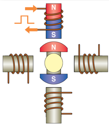
Image Source : https://electricalworkbook.com/stepper-motor/
The operation of a stepper motor relies on the sequential energization of its stator coils. In the given example (Figure a), the motor has four coils arranged at 90-degree intervals. When a coil is energized by a current pulse, it generates a magnetic field that attracts the rotor’s permanent magnet, causing the shaft to rotate by a fixed step angle (in this case, 90 degrees). By activating the coils in a specific order (e.g., Coil 1 → Coil 2 → Coil 3 → Coil 4), the motor moves in precise increments. The direction of rotation (clockwise or counterclockwise) is determined by the sequence in which the coils are energized.
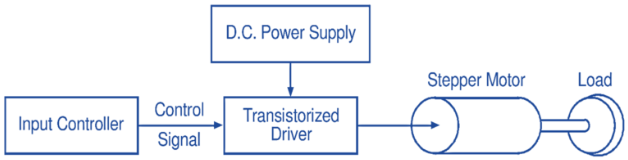
Image Source : https://electricalworkbook.com/stepper-motor/
Stepper motors require an external control system to function effectively. As shown in the second image, a DC power supply provides the necessary voltage, while an input from a microcontroller sends control signals to a transistorized driver. The driver amplifies these signals and delivers the appropriate current pulses to the motor coils, ensuring smooth and accurate movement. This setup allows for precise speed and position control without the need for feedback mechanisms, though some advanced systems use encoders for improved accuracy.
For more Info : https://electricalworkbook.com/stepper-motor/
DC Motor
A DC (Direct Current) motor is an electrical machine that converts DC electrical energy into mechanical motion. It operates based on the principle of electromagnetic induction, where a current-carrying conductor placed in a magnetic field experiences a force, causing rotation. The motor consists of key components such as the stator (which generates a stationary magnetic field), the rotor (or armature, which rotates when current flows through its windings), and the commutator with brushes (which ensures unidirectional torque by reversing current direction as the rotor turns). DC motors are known for their simplicity, high starting torque, and ease of speed control, making them ideal for applications like electric vehicles, conveyor systems, and household appliances. However, brush wear in traditional DC motors limits their lifespan, leading to the adoption of brushless DC (BLDC) motors in modern applications for improved efficiency and durability.
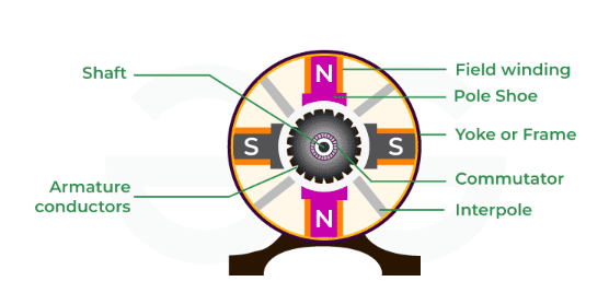
Image Source : https://www.geeksforgeeks.org/physics/dc-motor/
A4953
The A4953 is a small but powerful motor driver that helps control DC motors and stepper motors. It acts like a switch that turns the motor on, off, changes direction, and controls speed using simple electrical signals. It works with a wide voltage range (4V to 40V), making it useful for different types of motors.
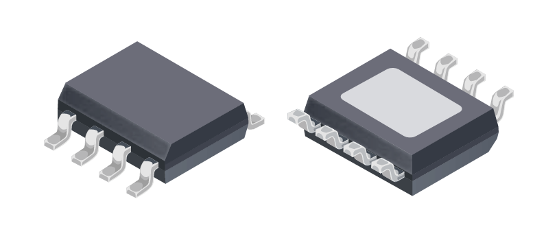
Image Source : https://www.adafruit.com/product/4953
The A4953 motor driver uses an H-Bridge circuit, which allows it to send power in both directions. This means it can make a motor spin forward or backward by changing signals on two input pins (IN1 and IN2). If you send a PWM signal (a type of fast on-off signal) to these pins, you can also control the motor's speed. If both inputs are LOW, the motor stops freely, and if both are HIGH, the motor brakes immediately.
One of the best features of the A4953 is its built-in protection. It has safeguards against overheating, too much current, and low voltage, so it doesn’t easily get damaged. It also has a SENSE pin that allows monitoring of the current, which is helpful when controlling stepper motors.
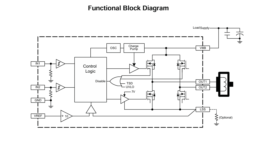
Image Source : https://www.adafruit.com/product/4953
To ensure the proper operation of the H-Bridge, two capacitors and a resistor need to be connected. I referred to the A4953 datasheet and found the recommended values for these components.
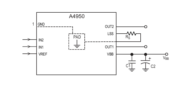
Image Source : https://www.adafruit.com/product/4953
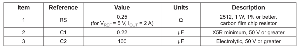
Image Source : https://www.adafruit.com/product/4953
AO3400A
The AO3400A is a small and efficient N-channel MOSFET used for controlling power in electronic circuits. It comes in a tiny SOT-23 package, making it great for small projects. This MOSFET is commonly used in motor control, LED dimming, battery-powered devices, and power management circuits.
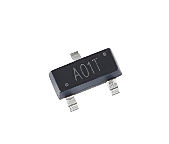
Image Source : https://www.diodes.com/assets/Datasheets/AO3400A.pdf
One of its key benefits is its low resistance when turned on (RDS(ON)), which helps reduce power loss and heat. It can be directly controlled by 3.3V and 5V microcontrollers like Arduino, ESP32, and ATtiny, making it easy to use in embedded systems. The AO3400A also supports fast switching, which makes it useful for PWM applications like adjusting motor speed or LED brightness.
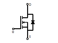
Image Source : https://www.diodes.com/assets/Datasheets/AO3400A.pdf
This MOSFET can handle up to 5.8A of current and works with voltages up to 30V. It turns on easily with low voltage signals, thanks to its low gate threshold voltage (VGS(th)) of around 1V to 3V
Micro controller
This week, I chose the ATtiny1614 because it is compact and has enough pins for my assignments. The ATtiny1614 is an 8-bit microcontroller from the ATtiny 1-series, featuring 14 pins, including 12 I/O pins, making it suitable for small projects.
It runs at up to 20MHz, has 16KB of flash memory, 2KB of SRAM, and 256 bytes of EEPROM for storing small amounts of data. It supports communication protocols like I²C, SPI, and UART, making it versatile for various applications. Additionally, it operates at 1.8V to 5.5V, allowing flexibility with different power sources.
Its compact size and low power consumption make it ideal for embedded systems, sensor applications, and small automation projects.
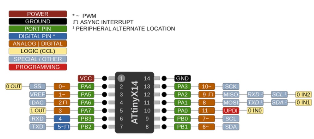
Image Source : https://www.microchip.com/en-us/product/ATtiny1614
Board Design
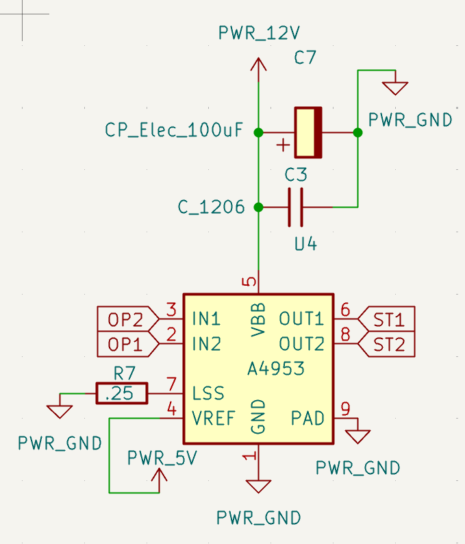
For this week, I designed a board incorporating all the components mentioned above, with the schematic shown below. This board features two H-Bridges, one MOSFET, a power regulation circuit, a power LED, a programmable LED, and two output connectors using JST. The design ensures efficient motor control and power management while maintaining a compact and functional layout.
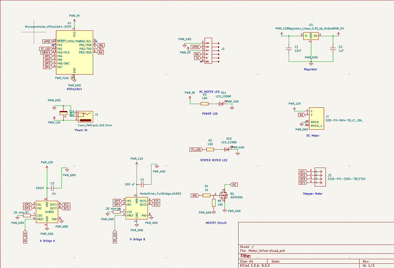
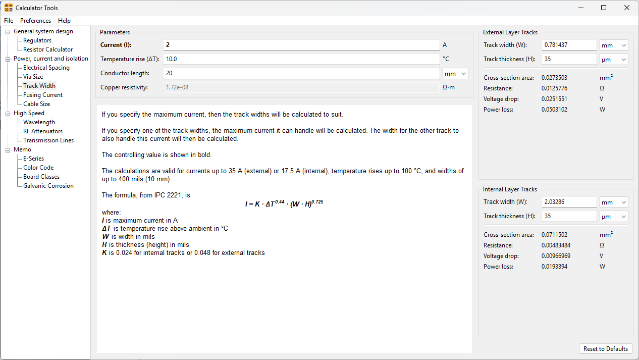
Since my circuit operates at multiple voltage levels, I had to design separate tracks for the 12V circuit and the 5V circuit. To ensure proper current handling and minimize resistance, I used KiCad’s built-in track width calculator. I provided the necessary parameters, including conductor thickness, conductor length, and track width, to determine the appropriate trace dimensions for each voltage level. This approach helps maintain efficient power distribution and prevents overheating or voltage drops in the circuit.
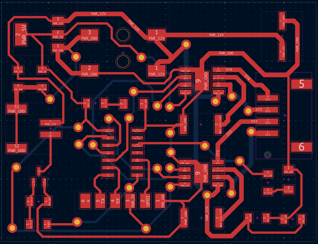
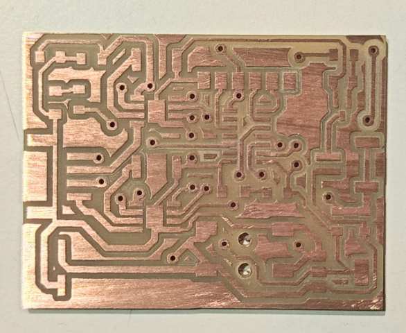
This is a multilayer board and this is the top tracks of the circuit
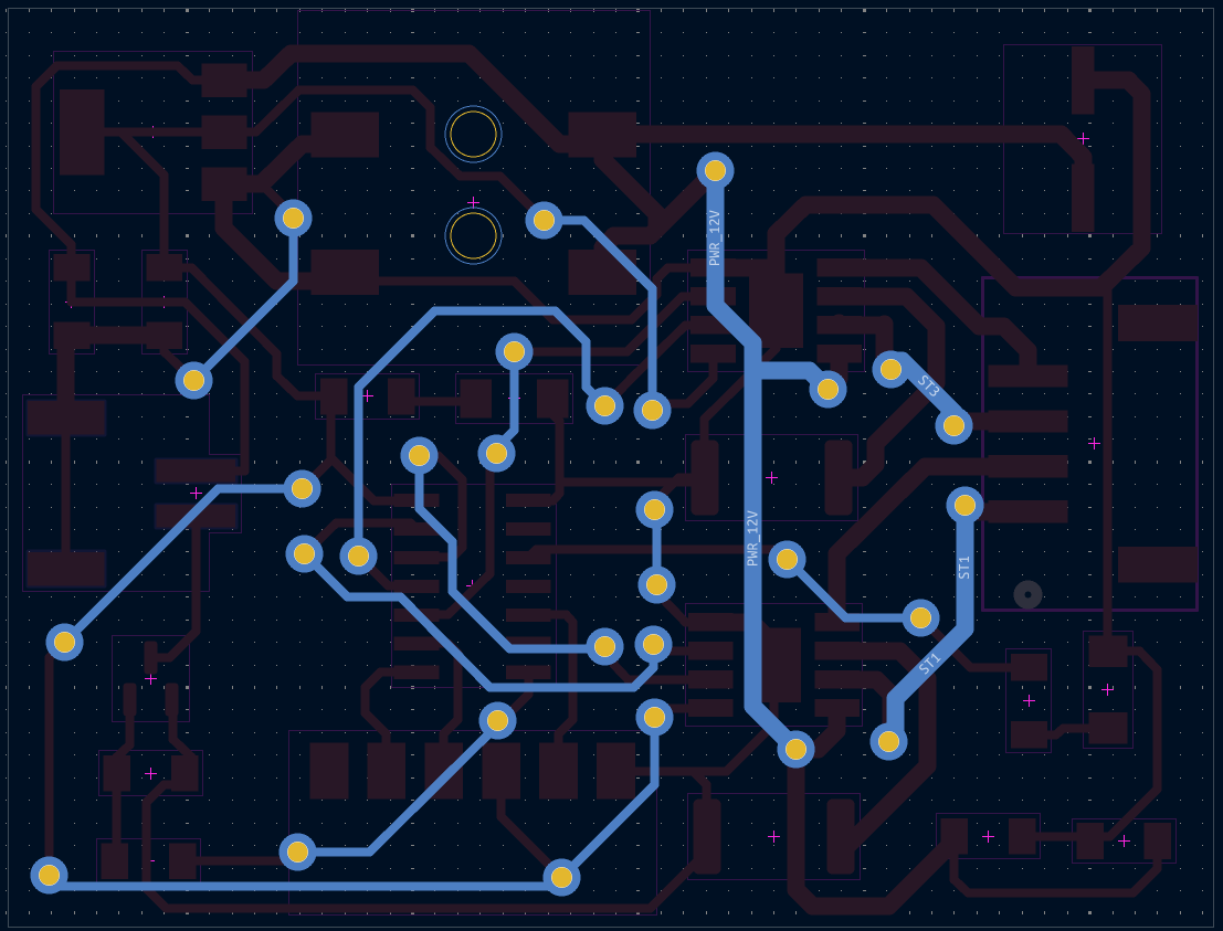
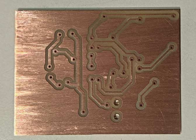
This is the bottom tracks of the circuit
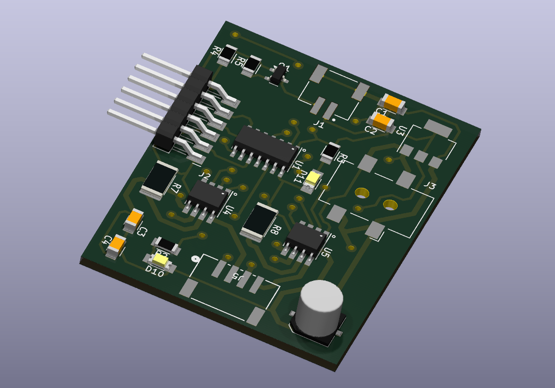
This is the 3D model of the board from kicad
This is the board after milling.
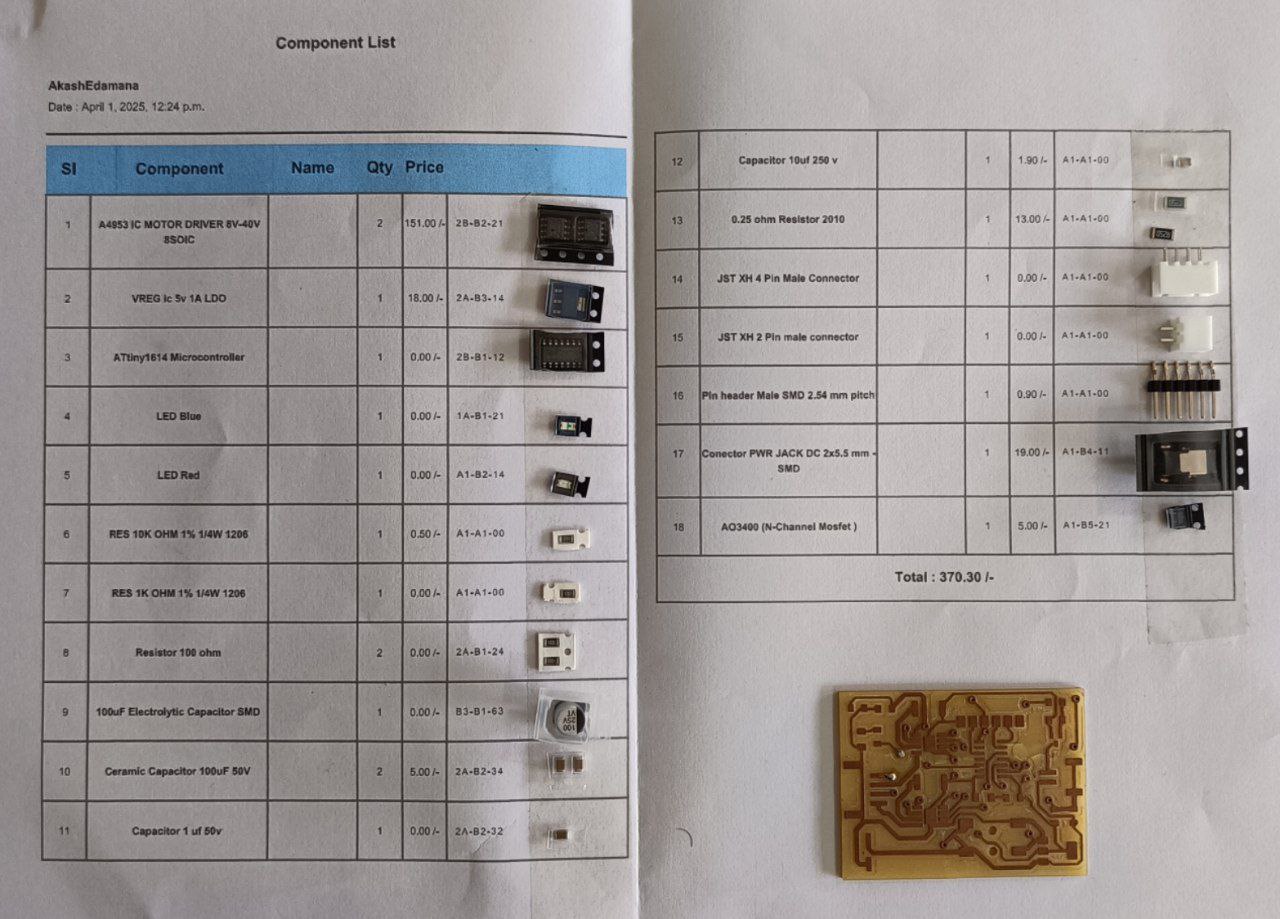
These are all the components included in the board, but I mistakenly left out a diode, which caused a major issue. I will explain the impact of this later.
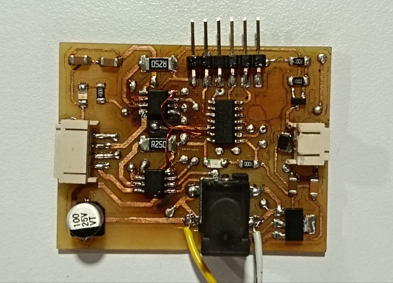
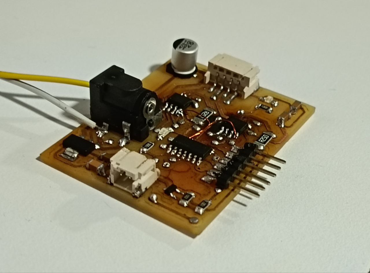
This is the board after soldering all the components. I used a hot air gun to solder the components, which worked well for most of them. However, I faced some challenges with the MOSFET and H-Bridge due to their small size. I had to use a soldering iron for these components, which was a bit tricky.
I also added a 100uF capacitor to the power supply to ensure stable voltage levels. This capacitor helps smooth out any voltage fluctuations and provides a more reliable power source for the components.
Pin Out
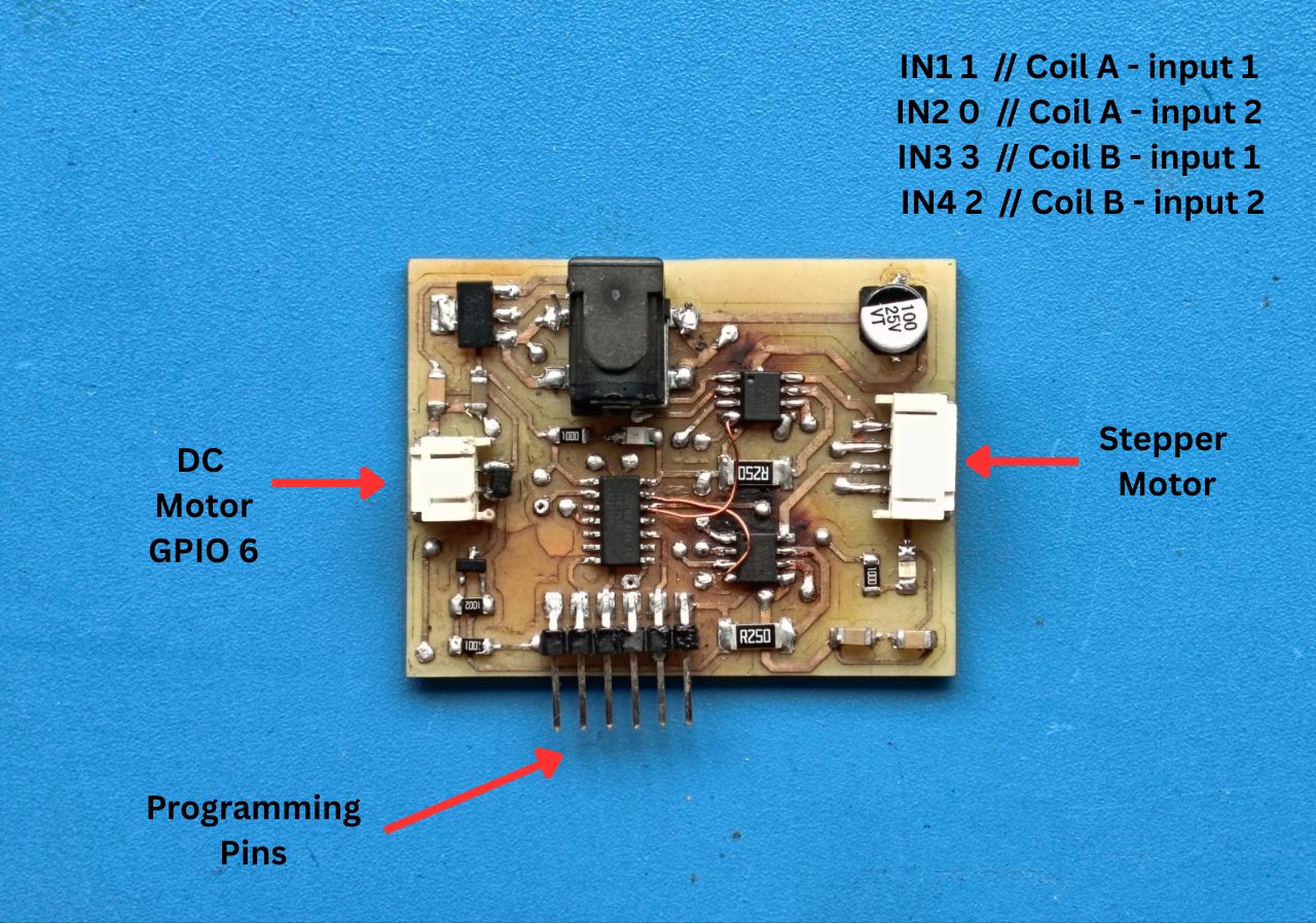
This is the pinout of the board. The pins are labeled as follows:And since any GPIO pins can be used i referred the pin out and chose the ones which are suitable
Programming
DC Motor & MOSFET Test 1
This is the code for controlling the DC motor using a MOSFET. The code uses PWM to switch on and off the motor.
   // Define the pin connected to the motor
#define MOTOR_PIN 6

void setup() {
  // Set the motor pin as an OUTPUT pin
  pinMode(MOTOR_PIN, OUTPUT);
}

void loop() {
  // Turn the motor ON at full speed (PWM value 255)
  analogWrite(MOTOR_PIN, 255);
  delay(100);  // Keep the motor running for 100 milliseconds

  // Turn the motor OFF (PWM value 0)
  analogWrite(MOTOR_PIN, 0);
  delay(1000);  // Wait for 1 second before repeating the loop
}
AI has been used to add comments to the code for better understanding.
DC Motor & MOSFET Test 2
This is the code for controlling the DC motor using a MOSFET. The code uses PWM and starts from max speed and goes down step by step inside the loop.
      // Define the pin connected to the gate of the MOSFET controlling the DC motor
#define MOTOR_PIN 6

void setup() {
  // Set the motor control pin as an output
  pinMode(MOTOR_PIN, OUTPUT);
}

void loop() {
  // These analogWrite values represent different speeds (PWM duty cycles) for the DC motor.
  // By changing the speed in specific timing patterns, you're trying to create a sound/tune effect.

  analogWrite(MOTOR_PIN, 200);  // Medium-high speed
  delay(800);                   // Run for 800 ms

  analogWrite(MOTOR_PIN, 100);  // Lower speed
  delay(500);                   // Run for 500 ms

  analogWrite(MOTOR_PIN, 255);  // Full speed
  delay(300);                   // Run for 300 ms

  analogWrite(MOTOR_PIN, 150);  // Moderate speed
  delay(300);                   // Run for 300 ms

  analogWrite(MOTOR_PIN, 100);  // Lower speed again
  delay(300);                   // Run for 300 ms

  analogWrite(MOTOR_PIN, 255);  // Full speed
  delay(1000);                  // Run for 1 second

  analogWrite(MOTOR_PIN, 200);  // Medium-high speed
  delay(1000);                  // Run for 1 second

  analogWrite(MOTOR_PIN, 100);  // End with a low speed
  delay(1000);                  // Run for 1 second
}
AI has been used to add comments to the code for better understanding.
DC Motor & H-Bridge
This is the code for controlling a DC motor using an H-Bridge. The code uses PWM to control the speed of the motor and switches the direction of rotation.
     // Define motor control pins
#define INT1 2   // Direction control pin 1
#define INT2 3   // Direction control pin 2
#define PWM 10   // Speed control pin (PWM capable)

void setup() {
  // Set motor direction and speed control pins as outputs
  pinMode(INT1, OUTPUT);
  pinMode(INT2, OUTPUT);  // Corrected from INT1 (was mistakenly repeated)
  pinMode(PWM, OUTPUT);
}

void loop() {
  // Run motor in one direction with decreasing speed

  digitalWrite(INT1, HIGH);  // Set motor direction: forward
  digitalWrite(INT2, LOW);   // Set motor direction: forward
  analogWrite(PWM, 255);     // Full speed
  delay(2000);               // Run for 2 seconds

  analogWrite(PWM, 155);     // Medium speed
  delay(2000);               // Run for 2 seconds

  analogWrite(PWM, 100);     // Slower speed
  delay(2000);               // Run for 2 seconds

  analogWrite(PWM, 50);      // Even slower
  delay(2000);               // Run for 2 seconds

  analogWrite(PWM, 10);      // Very slow
  delay(2000);               // Run for 2 seconds
}
AI has been used to add comments to the code for better understanding.
Stepper motor & H-Bridge
This is the code for controlling a stepper motor using an H-Bridge. The code uses a simple stepping sequence to rotate the motor in both forward and backward directions.
      // Define H-Bridge control pins for the stepper motor coils
#define IN1 1  // Coil A - input 1
#define IN2 0  // Coil A - input 2
#define IN3 3  // Coil B - input 1
#define IN4 2  // Coil B - input 2

int stepDelay = 1;  // Delay between each step in milliseconds (controls motor speed)

void setup() {
  // Set all motor control pins as outputs
  pinMode(IN1, OUTPUT);
  pinMode(IN2, OUTPUT);
  pinMode(IN3, OUTPUT);
  pinMode(IN4, OUTPUT);
}

void stepForward() {
  // Step sequence to rotate the motor in the forward direction (clockwise)

  // Step 1
  digitalWrite(IN1, HIGH);
  digitalWrite(IN2, LOW);
  digitalWrite(IN3, HIGH);
  digitalWrite(IN4, LOW);
  delay(stepDelay);

  // Step 2
  digitalWrite(IN1, LOW);
  digitalWrite(IN2, HIGH);
  digitalWrite(IN3, HIGH);
  digitalWrite(IN4, LOW);
  delay(stepDelay);

  // Step 3
  digitalWrite(IN1, LOW);
  digitalWrite(IN2, HIGH);
  digitalWrite(IN3, LOW);
  digitalWrite(IN4, HIGH);
  delay(stepDelay);

  // Step 4
  digitalWrite(IN1, HIGH);
  digitalWrite(IN2, LOW);
  digitalWrite(IN3, LOW);
  digitalWrite(IN4, HIGH);
  delay(stepDelay);
}

void stepBackward() {
  // Step sequence to rotate the motor in the reverse direction (counter-clockwise)

  // Step 1 (reverse of stepForward's Step 4)
  digitalWrite(IN1, HIGH);
  digitalWrite(IN2, LOW);
  digitalWrite(IN3, LOW);
  digitalWrite(IN4, HIGH);
  delay(stepDelay);

  // Step 2
  digitalWrite(IN1, LOW);
  digitalWrite(IN2, HIGH);
  digitalWrite(IN3, LOW);
  digitalWrite(IN4, HIGH);
  delay(stepDelay);

  // Step 3
  digitalWrite(IN1, LOW);
  digitalWrite(IN2, HIGH);
  digitalWrite(IN3, HIGH);
  digitalWrite(IN4, LOW);
  delay(stepDelay);

  // Step 4
  digitalWrite(IN1, HIGH);
  digitalWrite(IN2, LOW);
  digitalWrite(IN3, HIGH);
  digitalWrite(IN4, LOW);
  delay(stepDelay);
}

void loop() {
  // Rotate the stepper motor forward by 200 steps
  // (One full rotation for a 1.8° stepper motor)
  for (int i = 0; i < 200; i++) {
    stepForward();
  }
  delay(1000);  // Wait for 1 second

  // Rotate the stepper motor backward by 200 steps
  for (int i = 0; i < 200; i++) {
    stepBackward();
  }
  delay(1000);  // Wait for 1 second
}
AI has been used to add comments to the code for better understanding.
Issues I faced
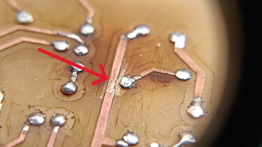
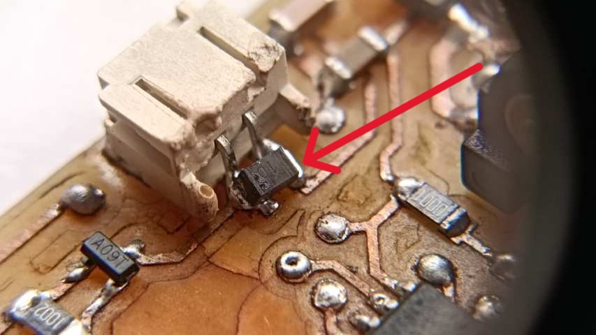
The first issue I faced was a short circuit where one of the 12V power lines was accidentally connected to my programmable LED pin. Additionally, the VCC pin was shorted to the signal pin of the MOSFET. I resolved this by manually scraping off the excess solder to break the unintended connections.
The next issue was the lack of a diode on the output pin of the DC motor. This caused a voltage spike (back EMF) when the motor was turned off, which damaged the MOSFET. Since the MOSFET failed in a shorted state, it allowed 12V to flow into the microcontroller, which also got damaged. As a result, I had to replace both the MOSFET and the microcontroller.
To prevent this issue in the future, I will add a flyback diode across the motor terminals to safely redirect the back EMF.
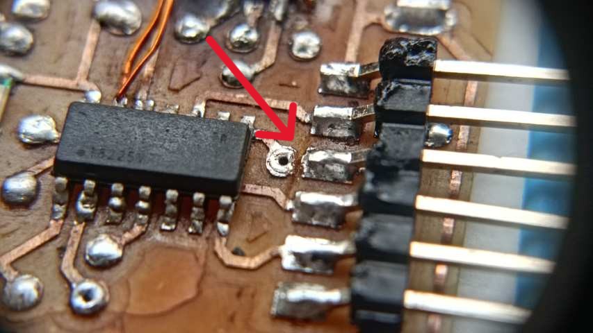
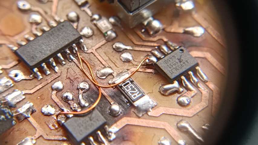
The final issue I faced was with the H-Bridge. I mistakenly connected the VREF pin to ground, which prevented proper motor control. Since VREF determines the reference voltage for current regulation, it needs to be controlled using PWM to adjust the motor speed with the `analogWrite()` function.
To fix this, I removed the unwanted traces and connected the VREF pin to a PWM-supported pin on the ATtiny1614 using a jumper wire. This allowed me to properly control the DC motor speed via PWM.
Conclusion
This week has been both fascinating and educational as I delved into DC motor control, stepper motors, and H-bridge MOSFET circuits. Although I encountered some setbacks—like damaging a MOSFET and a microcontroller—the hands-on experience was incredibly rewarding and deepened my understanding of these concepts.