FINAL PROJECT
Project Slide
Project Video
Project Overview
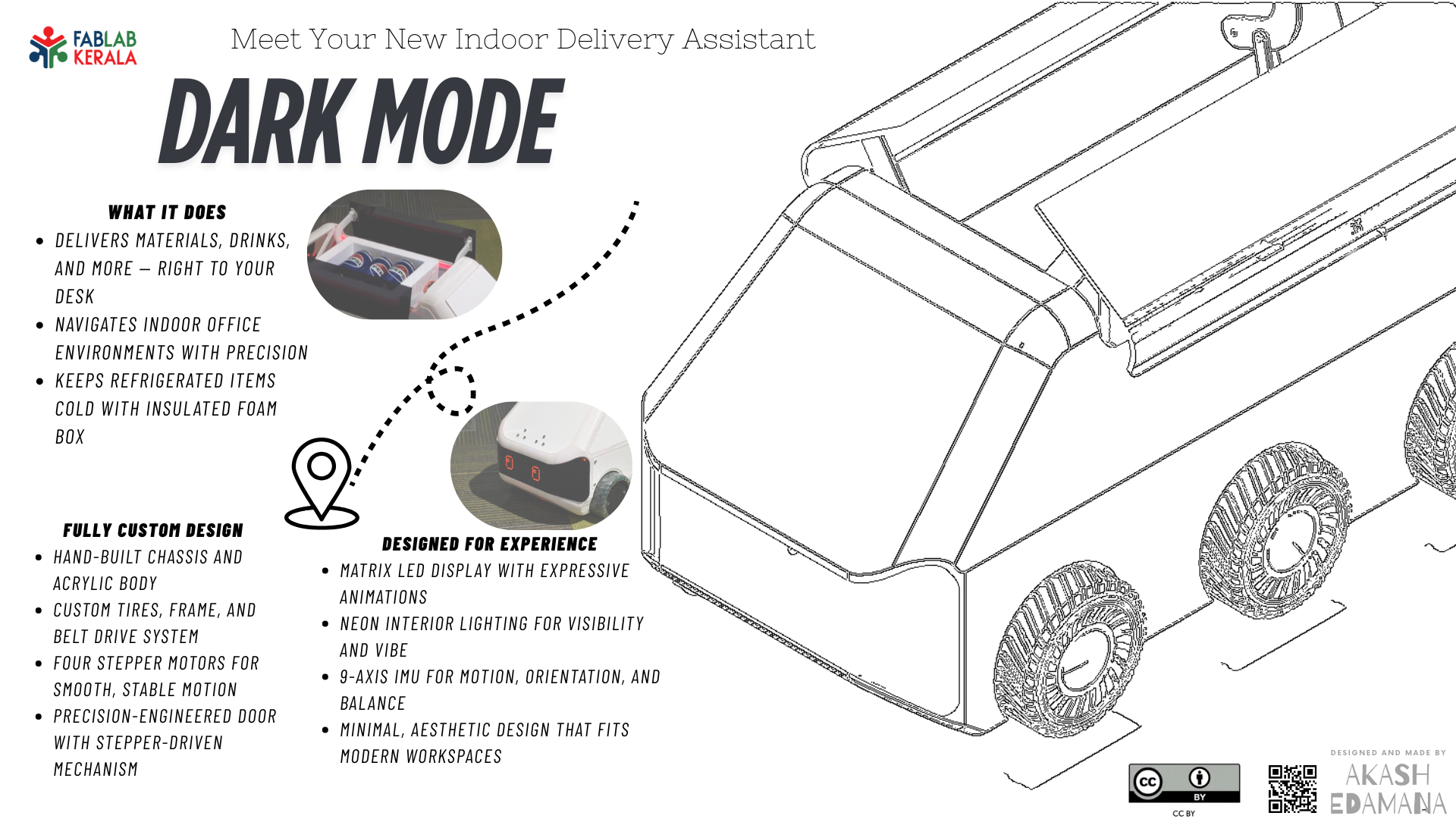
The final project is an indoor delivery robot designed to autonomously transport items such as food, drinks, or small packages within office spaces. The robot includes a robust driving mechanism, a motorized door, matrix LED displays for communication, and a Time-of-Flight sensor for obstacle detection. The design focused on ease of manufacturing, affordability, and practical utility within a workplace environment.

Inspiration & References
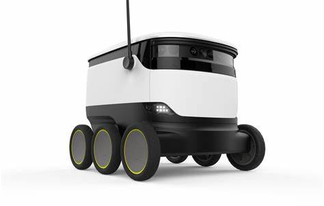
Inspiration for this robot came from commercial delivery robots by Pudu Robotics and Starship Deliveries. These projects demonstrated polished delivery solutions for food and goods. However, this project reimagined those concepts to suit simpler, more cost-effective office deployments, using tools and fabrication methods available in the Fab Lab.
Electronics
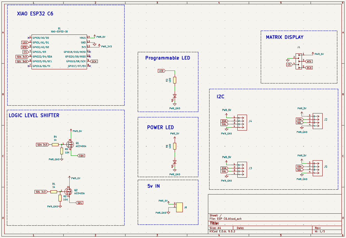
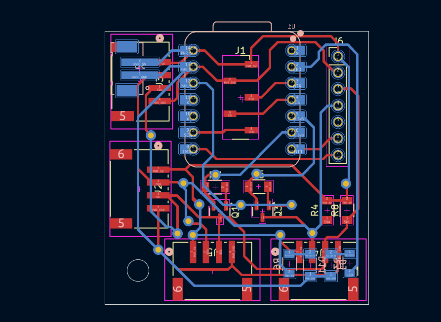
Main Board
Built around the XIAO ESP32-C6, this board handled Wi-Fi communication and served as the master controller. It interfaced with the motor, LED, and sensor boards through I2C. The board also included logic-level shifting to adapt 5V peripherals to the 3.3V ESP32 logic.
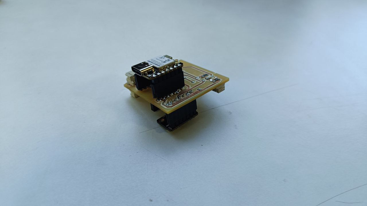
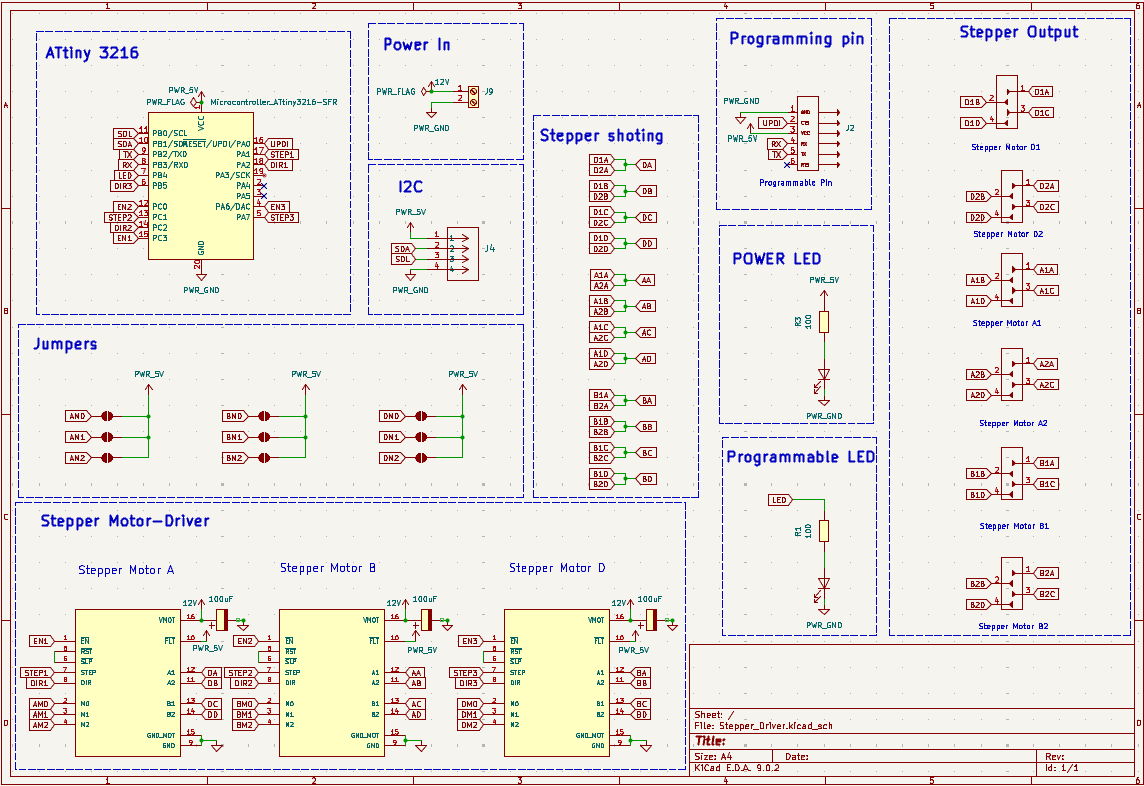
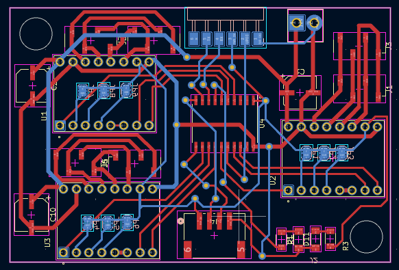
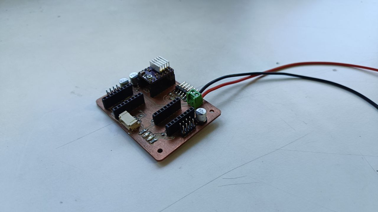
Motor Control Board
This board, based on ATtiny3216, drove five stepper motors using DRV8825 drivers — four for locomotion and one for the door mechanism. It featured I2C communication, improved solder pad design, and compact double-sided layout.
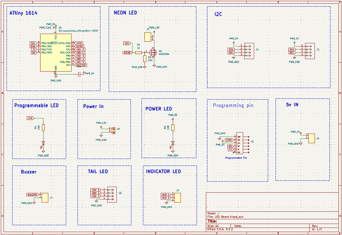
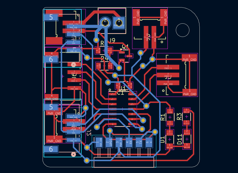
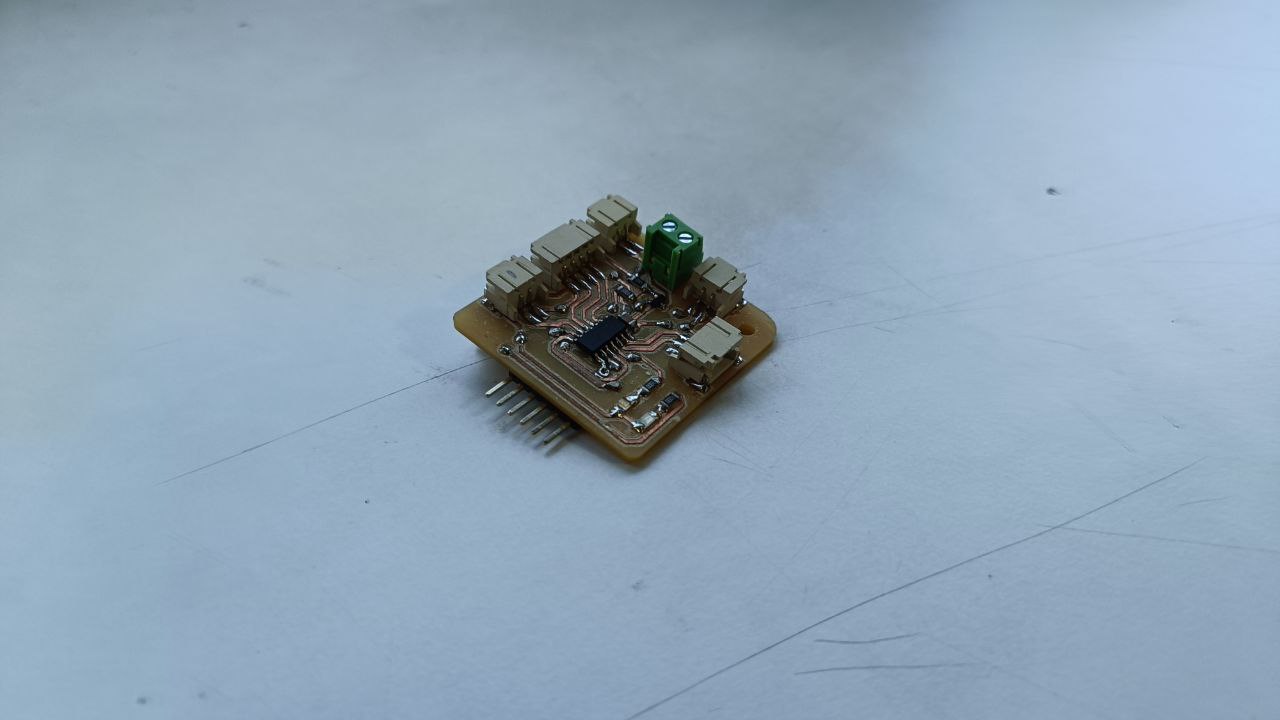
LED Control Board
Controlled by an ATtiny1614, this board powered a NeoPixel strip and 12V neon LEDs. It was designed to manage lighting patterns based on received I2C commands. JST headers were included for modularity.
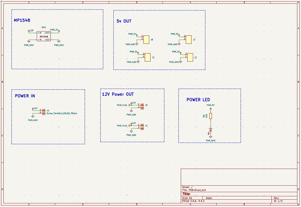
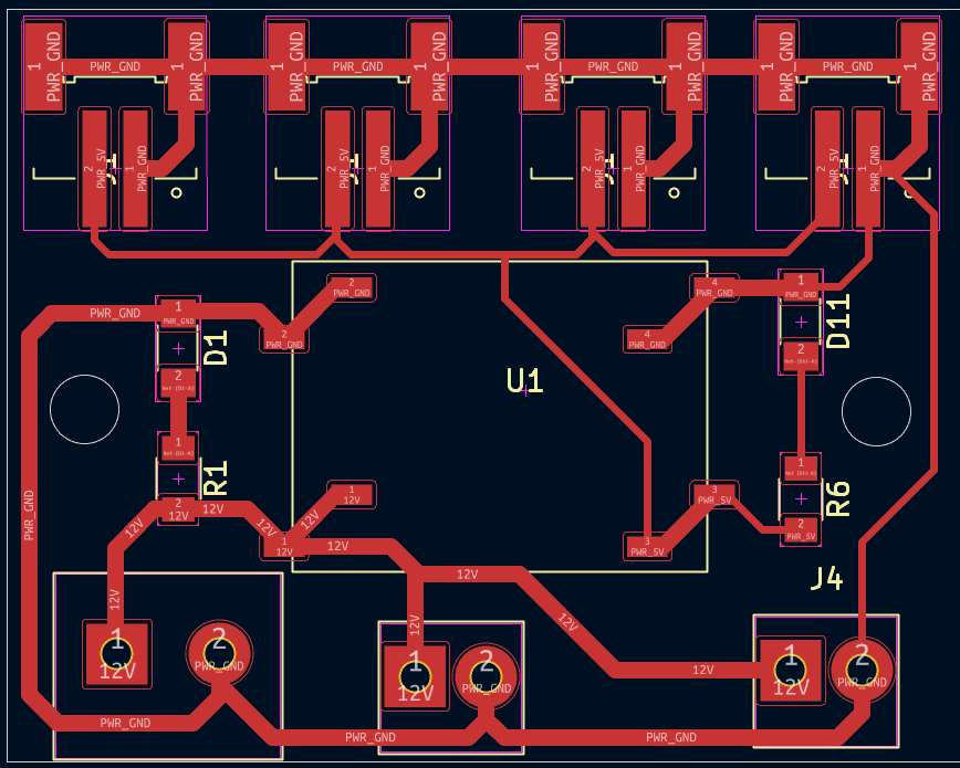
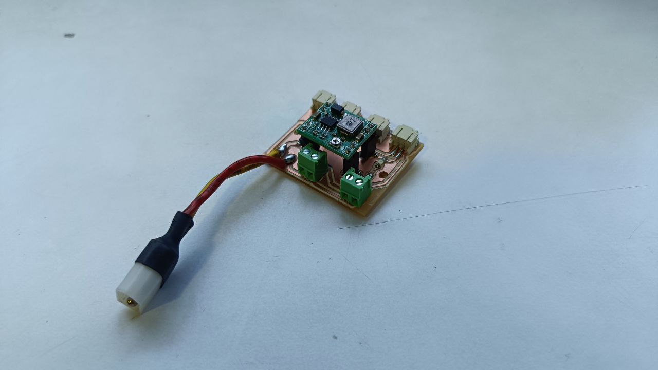
Power Distribution Board (PDB)
The PDB supplied power to all modules. It stepped down 12V from the LiPo battery to 5V using a buck converter. Terminals allowed distribution to multiple subsystems. A 3D-printed XT60 mount was added for safety and reliability.
For more detail Click Here >>>>PROJECT DEVELOPMENT
Design
The robot’s design was fully developed in Fusion 360. It included modular assemblies for the frame, wheel system, electronics housing, and door. Flat parts were optimized for acrylic laser cutting while curved shapes were formed via acrylic bending. Parts like wheel stoppers,internal brackets and curved parts of body were 3D printed for accuracy and fit.
For more detail Click Here >>>>PROJECT DEVELOPMENT
Assembly
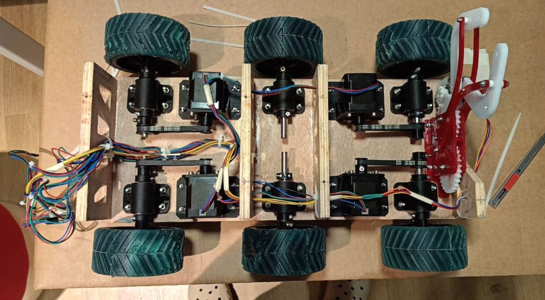
Base Assembly
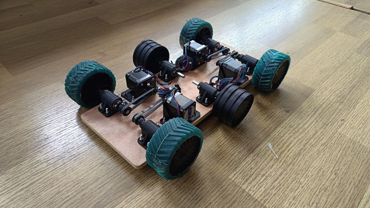
The base was CNC routed from 12mm plywood using the Zund machine. Grooves and slots were milled to host the driving components, including motors, wheels, bearings, and shafts. Slotted mounts allowed for tension adjustment and alignment of mechanical parts.
Middle Assembly
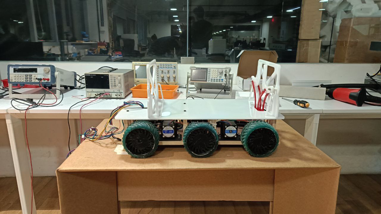
The middle section is another important component of the robot. It provides a platform for the container and all the boards. It was made from acrylic sheets and press fit and mounted to the base using screws.It also acts as a structural support for the body.
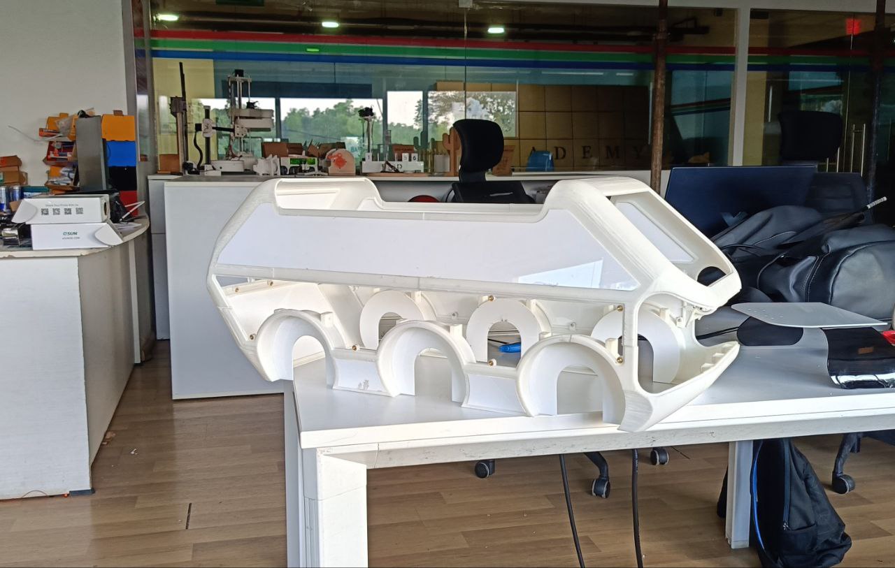
Body Assembly
The body frame was built using a mix of bent acrylic and 3D printed supports. Flat acrylic panels formed the outer shell while 3D printed connectors joined the frame together. Adhesive and screws were used to assemble it into a sturdy, detachable enclosure.
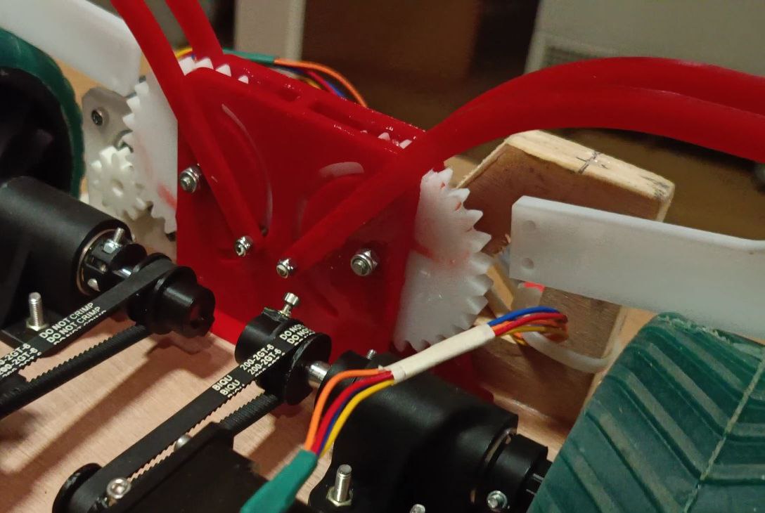
Mechanism Assembly
The door mechanism featured a gear system powered by a stepper motor. It was made from acrylic sheets and mounted using bearings. The two gear were acrylic cut and one gear was 3D printed and integrated with the bearings and screws to ensure smooth and precise motion.
For more detail Click Here >>>>PROJECT DEVELOPMENT
Wiring
All boards were connected using JST cables and pin headers. Stepper motors, LED strips, and sensors were wired with consideration for neatness and modularity. Wires were routed under the base and along grooves, held in place with zip ties and adhesive mounts.
For more detail Click Here >>>>PROJECT DEVELOPMENT
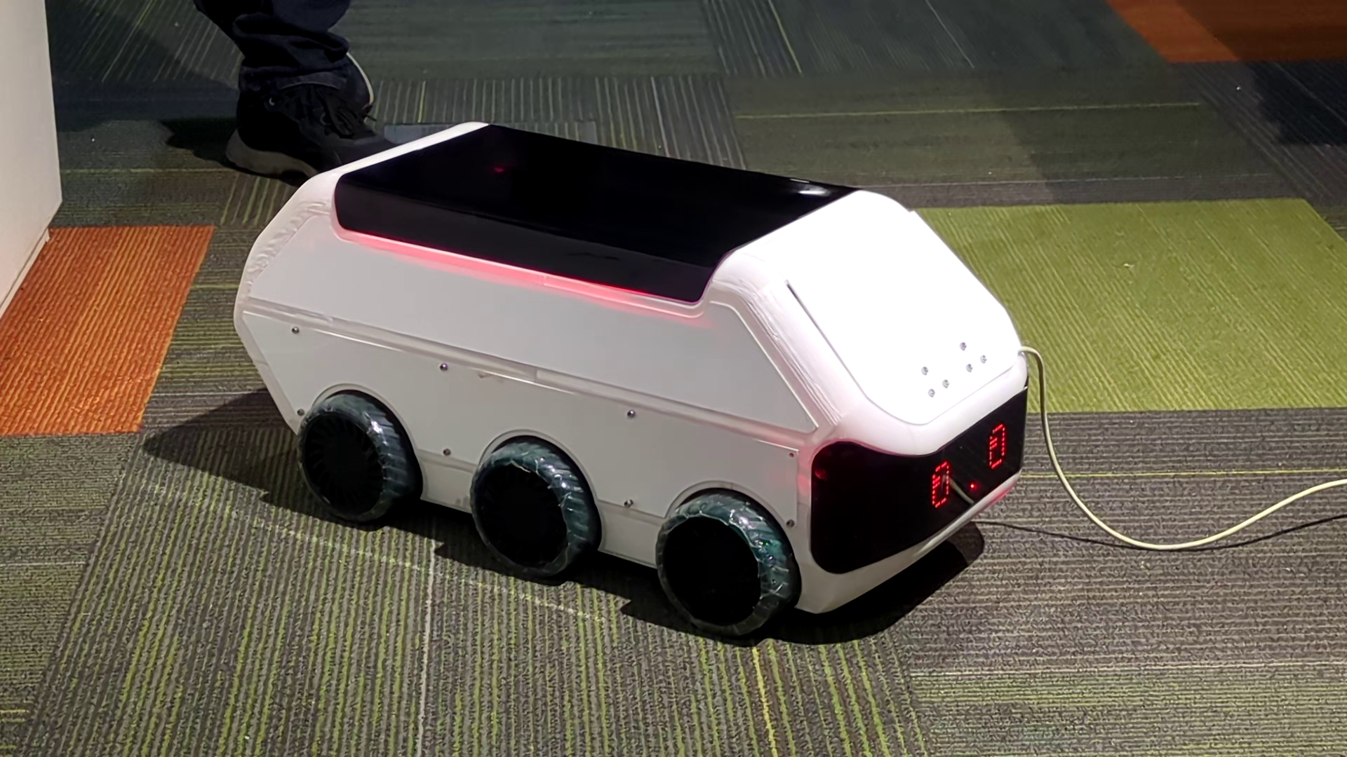
Final output
This is the final output of the project after all the assembly.
Programming
Since this system has three programmable board all of them have to be programmed separately so there are three different codes two of the boards are ATtiny's so they need a separate programmer to program them.Al of these boards communicate using I2C and is connected between each other using JST cables all the boards are separately powered and in the program there isa master board and the rest are slave boards all the slave boards are assigned with a different I2C address so board specific commands can be send and all the communication to the outside of the system is handled by the master board.
LED Board
This boar is used to control all the LED on the robot. It controls the NeoPixel strip and 12V neon LEDs and it also has ports for connecting extra leds if needed ,The libries tha are used are Wire.h and Adafruit_NeoPixel.h for the communication between the boards and the controlling of neopixel LEDs
#include <Adafruit_NeoPixel.h>
#include <Wire.h>

#define Neo_Pix_Pin 2
#define Neon_pin    8
#define Num_LED     14
#define I2C_ADDRESS 0x09

Adafruit_NeoPixel strip(Num_LED, Neo_Pix_Pin, NEO_GRB + NEO_KHZ800);

const long BlinkInterval = 300;
const long GreenBlinkTime = 6000;
const int AnimationDelay = 60;
const int AnimationLoops = 7;

bool neonBlinking = false;
int neonBlinkCount = 0;
bool neonState = true;
unsigned long neonLastBlinkTime = 0;

bool greenBlinking = false;
bool greenState = false;
unsigned long greenStartTime = 0;
unsigned long greenLastBlinkTime = 0;

bool rightAnimating = false;
int rightStep = 0;
int rightLoops = 0;

bool leftAnimating = false;
int leftStep = 0;
int leftLoops = 0;

bool reverseAnimating = false;
int reverseStep = 0;
int reverseLoops = 0;

void setup() {
  strip.begin();
  strip.setBrightness(50);
  strip.show();

  pinMode(Neon_pin, OUTPUT);
  digitalWrite(Neon_pin, HIGH);  // Always ON initially

  Serial.begin(9600);
  Wire.begin(I2C_ADDRESS);
  Wire.onReceive(receiveEvent);
}

void loop() {
  // Default red
  if (!greenBlinking && !leftAnimating && !rightAnimating && !reverseAnimating) {
    for (int i = 0; i < Num_LED; i++) strip.setPixelColor(i, strip.Color(255, 0, 0));
    strip.show();
  }

  if (neonBlinking) handleNeonBlink();
  if (greenBlinking) handleGreenBlink();
  if (rightAnimating) handleRightAnimation();
  if (leftAnimating) handleLeftAnimation();
  if (reverseAnimating) handleReverseAnimation();
}

// === I2C Command Handler ===
void receiveEvent(int howMany) {
  if (howMany < 1) return;
  char cmd = Wire.read();
  Serial.print("Received command: ");
  Serial.println(cmd);

  switch (cmd) {
    case 'L':
      leftAnimating = true;
      leftStep = 0;
      leftLoops = 0;
      break;
    case 'R':
      rightAnimating = true;
      rightStep = 0;
      rightLoops = 0;
      break;
    case 'B':
      reverseAnimating = true;
      reverseStep = 0;
      reverseLoops = 0;
      break;
    case 'O':
    case 'C':
      neonBlinking = true;
      neonBlinkCount = 0;
      neonLastBlinkTime = millis();
      digitalWrite(Neon_pin, HIGH);
      greenBlinking = true;
      greenStartTime = millis();
      greenLastBlinkTime = millis();
      break;
  }
}

// === Animation Functions ===

void handleNeonBlink() {
  if (millis() - neonLastBlinkTime >= BlinkInterval) {
    neonLastBlinkTime = millis();
    neonState = !neonState;
    digitalWrite(Neon_pin, neonState ? HIGH : LOW);

    if (!neonState) neonBlinkCount++;

    if (neonBlinkCount >= 10) {
      neonBlinking = false;
      digitalWrite(Neon_pin, HIGH);  // Ensure ON
    }
  }
}

void handleGreenBlink() {
  if (millis() - greenLastBlinkTime >= BlinkInterval) {
    greenLastBlinkTime = millis();
    greenState = !greenState;
    for (int i = 0; i < Num_LED; i++)
      strip.setPixelColor(i, greenState ? strip.Color(0, 255, 0) : strip.Color(255, 0, 0));
    strip.show();
  }
  if (millis() - greenStartTime >= GreenBlinkTime) {
    greenBlinking = false;
    for (int i = 0; i < Num_LED; i++)
      strip.setPixelColor(i, strip.Color(255, 0, 0));
    strip.show();
  }
}

void handleLeftAnimation() {
  static unsigned long lastStep = 0;
  if (millis() - lastStep >= AnimationDelay) {
    lastStep = millis();
    strip.clear();
    for (int i = 0; i <= 6; i++) {
      int distance = abs(i - leftStep);
      int brightness = max(0, 255 - distance * 60);
      strip.setPixelColor(i, strip.Color(brightness, brightness / 2, 0));  // Amber
    }
    strip.show();
    leftStep++;
    if (leftStep > 8) {
      leftStep = 0;
      leftLoops++;
      if (leftLoops >= AnimationLoops) leftAnimating = false;
    }
  }
}

void handleRightAnimation() {
  static unsigned long lastStep = 0;
  if (millis() - lastStep >= AnimationDelay) {
    lastStep = millis();
    strip.clear();
    for (int i = 13; i >= 7; i--) {
      int distance = abs(i - (13 - rightStep));
      int brightness = max(0, 255 - distance * 60);
      strip.setPixelColor(i, strip.Color(brightness, brightness / 2, 0));
    }
    strip.show();
    rightStep++;
    if (rightStep > 8) {
      rightStep = 0;
      rightLoops++;
      if (rightLoops >= AnimationLoops) rightAnimating = false;
    }
  }
}

void handleReverseAnimation() {
  static unsigned long lastStep = 0;
  if (millis() - lastStep >= AnimationDelay) {
    lastStep = millis();
    strip.clear();
    int center1 = 6;
    int center2 = 7;
    for (int i = 0; i <= reverseStep; i++) {
      int brightness = constrain(i * 40, 0, 255);
      if (center1 - i >= 0) strip.setPixelColor(center1 - i, strip.Color(0, 0, brightness));
      if (center2 + i < Num_LED) strip.setPixelColor(center2 + i, strip.Color(0, 0, brightness));
    }
    strip.show();
    reverseStep++;
    if (center1 - reverseStep < 0 && center2 + reverseStep >= Num_LED) {
      reverseStep = 0;
      reverseLoops++;
      if (reverseLoops >= AnimationLoops) reverseAnimating = false;
    }
  }
}
Motor Board
The motor board is responsible for controlling the motors and ensuring smooth operation. This board controls the motors for the driving systems well as the motor of the door mechanism here Wire.h library were used for communication and the AccelStepper & MultiStepper.h library was used to control the motors. I used the I2C protocol to communicate with the main board.
          #include <Wire.h>
          #include <AccelStepper.h>
          #include <MultiStepper.h>

          // I2C Slave Address
          #define I2C_SLAVE_ADDR 0x08

          // Motor 1 (Door)
          #define STEP1 3
          #define DIR1 4
          #define EN1 2

          // Motor 2 (Left Drive)
          #define STEP2 11
          #define DIR2 12
          #define EN2 10

          // Motor 3 (Right Drive)
          #define STEP3 15
          #define DIR3 16
          #define EN3 13

          // Stepper motor instances
          AccelStepper doorMotor(AccelStepper::DRIVER, STEP1, DIR1);
          AccelStepper leftMotor(AccelStepper::DRIVER, STEP2, DIR2);
          AccelStepper rightMotor(AccelStepper::DRIVER, STEP3, DIR3);

          // MultiStepper for synchronized drive motion
          MultiStepper driveMotors;

          // Motion parameters
          int speedForward = 1000;
          int speedBackward = 1000;
          int speedTurn = 1500;
          int doorSpeed = 1000;
          int doorAccel = 800;

          long stepsToMove = 7500;
          long steps_Door = 7500;

          bool doorOpened = false;

          // I2C command buffers
          volatile char receivedCommand = 0;
          volatile int receivedValue = 0;
          volatile bool newCommandReceived = false;

          void receiveEvent(int numBytes) {
            if (numBytes < 5) return;

            byte buffer[5];
            for (int i = 0; i < 5 && Wire.available(); i++) {
              buffer[i] = Wire.read();
            }

            receivedCommand = (char)buffer[0];
            memcpy((void *)&receivedValue, &buffer[1], sizeof(int));
            newCommandReceived = true;
          }

          void setup() {
            Serial.begin(9600);
            while (!Serial);  // Wait for Serial monitor

            // Setup I2C
            Wire.begin(I2C_SLAVE_ADDR);
            Wire.onReceive(receiveEvent);

            // Enable all motors
            pinMode(EN1, OUTPUT);
            pinMode(EN2, OUTPUT);
            pinMode(EN3, OUTPUT);
            digitalWrite(EN1, LOW);
            digitalWrite(EN2, LOW);
            digitalWrite(EN3, LOW);

            // Setup stepper parameters
            doorMotor.setMaxSpeed(doorSpeed);
            doorMotor.setAcceleration(doorAccel);

            leftMotor.setMaxSpeed(speedForward);
            leftMotor.setAcceleration(500);
            rightMotor.setMaxSpeed(speedForward);
            rightMotor.setAcceleration(500);

            driveMotors.addStepper(leftMotor);
            driveMotors.addStepper(rightMotor);

            Serial.println("Motor Driver Board Ready");
          }

          void loop() {
            if (newCommandReceived) {
              newCommandReceived = false;

              // Display received data
              Serial.print("Received Command: ");
              Serial.print(receivedCommand);
              Serial.print(" | Value: ");
              Serial.println(receivedValue);

              // Update stepsToMove for motion
              if (receivedCommand == 'F' || receivedCommand == 'B' ||
                  receivedCommand == 'L' || receivedCommand == 'R') {
                stepsToMove = receivedValue;
              }

              // Handle commands
              switch (receivedCommand) {
                case 'F': goForward(); break;
                case 'B': goBackward(); break;
                case 'L': turnLeft(); break;
                case 'R': turnRight(); break;
                case 'O': openDoor(); break;
                case 'C': closeDoor(); break;
                default:
                  Serial.println("Unknown command");
              }
            }
          }

          // === Drive Functions ===

          void goForward() {
            long positions[2];
            positions[0] = leftMotor.currentPosition() + stepsToMove;
            positions[1] = rightMotor.currentPosition() + stepsToMove;
            driveMotors.moveTo(positions);
            driveMotors.runSpeedToPosition();
          }

          void goBackward() {
            long positions[2];
            positions[0] = leftMotor.currentPosition() - stepsToMove;
            positions[1] = rightMotor.currentPosition() - stepsToMove;
            driveMotors.moveTo(positions);
            driveMotors.runSpeedToPosition();
          }

          void turnLeft() {
            long positions[2];
            positions[0] = leftMotor.currentPosition() - stepsToMove;
            positions[1] = rightMotor.currentPosition() + stepsToMove;
            driveMotors.moveTo(positions);
            driveMotors.runSpeedToPosition();
          }

          void turnRight() {
            long positions[2];
            positions[0] = leftMotor.currentPosition() + stepsToMove;
            positions[1] = rightMotor.currentPosition() - stepsToMove;
            driveMotors.moveTo(positions);
            driveMotors.runSpeedToPosition();
          }

          // === Door Functions ===

          void openDoor() {
            if (!doorOpened) {
              doorMotor.moveTo(doorMotor.currentPosition() - steps_Door);
              doorMotor.runToPosition();
              doorOpened = true;
              Serial.println("Door opened");
            }
          }

          void closeDoor() {
            if (doorOpened) {
              doorMotor.moveTo(doorMotor.currentPosition() + steps_Door);
              doorMotor.runToPosition();
              doorOpened = false;
              Serial.println("Door closed");
            }
          }
Master Board
The master board is responsible for receiving commands from the controlling device and sends those information to the motor board and the LED board this board is where the main logic is made for example when turn left command is received it will send that command to the motor board to start the pre set operation to turn left to start and in parallel it will send the same command to the LED board to turn. I used the Serial library to communicate with the motor board.
For more detail Click Here >>>>PROJECT DEVELOPMENT
#include <Wire.h>

#define MOTOR_BOARD_ADDR 0x08  // Motor control board
#define LED_BOARD_ADDR   0x09  // LED board

void setup() {
  Serial.begin(115200);
  Wire.begin();
  Serial.println("Enter commands (e.g., F1000 B2000 L R O C):");
}

void loop() {
  if (Serial.available()) {
    String inputLine = Serial.readStringUntil('\n');
    inputLine.trim();
    if (inputLine.length() == 0) return;

    // Split the input line into separate commands
    int startIdx = 0;
    while (startIdx < inputLine.length()) {
      // Find the next space (command separator)
      int spaceIdx = inputLine.indexOf(' ', startIdx);
      if (spaceIdx == -1) spaceIdx = inputLine.length();

      // Extract one command token
      String token = inputLine.substring(startIdx, spaceIdx);
      token.trim();

      if (token.length() > 0) {
        char command = toupper(token.charAt(0));
        int value = 0;

        if (token.length() > 1) {
          value = token.substring(1).toInt();
        }

        Serial.print("Sending Command: ");
        Serial.print(command);
        Serial.print(" | Value: ");
        Serial.println(value);

        // Send to motor board (always)
        Wire.beginTransmission(MOTOR_BOARD_ADDR);
        Wire.write((uint8_t)command);
        Wire.write((byte *)&value, sizeof(int));
        Wire.endTransmission();
        delay(10);

        // Also send to LED board if it’s an LED command
        if (command == 'L' || command == 'R' || command == 'O' || command == 'C' || command == 'B') {
          Wire.beginTransmission(LED_BOARD_ADDR);
          Wire.write((uint8_t)command);
          Wire.endTransmission();
          delay(10);
        }
      }

      // Move to next token
      startIdx = spaceIdx + 1;
    }

    Serial.println("All commands sent.\n");
  }
}
For more detail Click Here >>>>PROJECT DEVELOPMENT
Testing
Each module was tested independently and then integrated. The door mechanism was calibrated based on step count, motors were tuned for current and speed, and I2C communication was verified. Full system tests ensure, display animations, and control functions operated as expected.
For more detail Click Here >>>>PROJECT DEVELOPMENT
Bill of Materials (BOM)
The BOM includes all electronic and mechanical components used in the final build — from microcontrollers and sensors to raw materials like wood, PLA, and acrylic. A compiled list is shown below.
| Si.No | Component | Quantity | Price per Unit (₹) |
|---|---|---|---|
| 1 | Power Beck MP1548 | 2 | ₹ 41.00 |
| 2 | Nema 17 Stepper Motor 17HS19-2004S1 | 5 | ₹ 2,882.00 |
| 3 | Driver DVR 8825 | 3 | ₹ 94.00 |
| 4 | NeoPixel Strip | 1 | ₹ 300.00 |
| 5 | ATtiny 3216 | 1 | ₹ 112.00 |
| 6 | ATtiny 1614 | 1 | ₹ 110.00 |
| 7 | XIAO ESP32C6 | 1 | ₹ 555.00 |
| 8 | LiPo Battery | 1 | ₹ 2,922.00 |
| 9 | Matrix LED MD MAX72XX | 2 | ₹ 249.00 |
| 10 | Time-of-Flight distance sensor VL53L0X | 1 | ₹ 152.00 |
| 11 | 2Z 608 Bearing | 12 | ₹ 148.00 |
| 12 | 8mm Dia Shaft (500mm) | 2 | ₹ 284.00 |
| 13 | Screw Terminal 2Pos | 4 | ₹ 14.00 |
| 14 | Resistor 100 Ohm | 6 | ₹ 1.00 |
| 15 | Resistor 1K Ohm 1% 1/4W 1206 | 4 | ₹ 1.00 |
| 16 | Capacitor 1µF 50V | 2 | ₹ 2.00 |
| 17 | LED (Red, Green, Blue) | 8 | ₹ 2.00 |
| 18 | JST XH 2-Pin Male Connector | 4 | ₹ 3.00 |
| 19 | JST XH 3-Pin Male Connector | 1 | ₹ 3.50 |
| 20 | JST XH 4-Pin Male Connector | 10 | ₹ 4.00 |
| 21 | Pin Header Male (2.54mm) | 30 | ₹ 1.00 |
| 22 | Logic Level Shifter / MOSFET | 1 | ₹ 20.00 |
| 23 | Electrolytic Capacitor 100µF | 3 | ₹ 3.00 |
| 24 | Acrylic 8mm | 1 | ₹ 3.00 |
| 25 | Acrylic 2mm | 1 | ₹ 3.00 |
| 26 | Smoked Acrylic 2mm | 1 | ₹ 3.00 |
| 27 | 12 mm plywood | 3 | ₹ 3.00 |
| 28 | Resin | 3 | ₹ 3.00 |
| 29 | PLA Filament | 3 | ₹ 3.00 |
| 30 | Glue | 1 | ₹ 3.00 |
For more detail Click Here >>>>PROJECT DEVELOPMENT