Project Development
What Tasks Have Been Completed, and What Tasks Remain?
Most of the major tasks have been completed within the planned schedule. I had accounted for a buffer period, and I was able to finish nearly all tasks toward the end of that buffer. The remaining tasks are mostly related to fine-tuning and post-processing.
Remaining Tasks:
What’s Working? What’s Not?
Several features are functioning well, while a few areas still need troubleshooting and optimization.
Working Well:
- The door mechanism is functioning fairly well and demonstrates the intended movement and mechanical behavior.
- All custom-designed electronic boards are working properly, except for one specific issue with the matrix LED display.
Not Working / Needs Improvement:
- The drive system is underperforming. The stepper motors are not providing sufficient torque to move the robot effectively, especially during tank turns. The combination of heavy structure, low motor torque, and high-traction tires is causing performance limitations.
- When the matrix LED display is connected to the main control board, the microcontroller becomes unresponsive ("bricked"), indicating a serious electrical or software issue.
- The Time-of-Flight sensor is not functioning correctly when mounted behind the smoked acrylic, possibly due to light attenuation.
What Questions Still Need to Be Resolved?
- Why is the main control board becoming unresponsive when the matrix LED is connected?
- What is the best way to prevent or reduce internal light bleeding through the white acrylic and 3D printed parts?
- How can the torque issue of the stepper motors be addressed? Should I consider switching to a different motor type?
What Will Happen Next?
After completing the documentation phase, I plan to:
- Begin post-processing of the body to improve surface quality and finish.
- Simultaneously resolve the door mechanism issues to ensure smooth opening and closing.
- Work on the driving system—possibly redesigning the control electronics or switching to a different motor—to improve performance.
What Have You Learned?
This project has been an immense learning experience in multiple areas:
- I have gained deeper knowledge of electronics and custom PCB design, including troubleshooting real-world integration issues.
- I learned how surface finishing can dramatically improve a project’s final appearance and usability.
- Working under time pressure helped me improve my problem-solving skills and decision-making during critical phases.
- I explored and applied a new method for acrylic bending, learning how to shape materials cleanly and accurately.
- I learned how to design aesthetically pleasing and functional mechanical components using both 3D printing and laser cutting.
- This experience taught me the importance of calculating torque, weight distribution, and mechanical loads—especially for motion-based projects.
- I understood the necessity of testing, especially for FDM 3D printed parts, to ensure alignment and reliability.
- Most importantly, I realized how essential research is before starting a complex project. A well-informed design phase can save a lot of time and effort later.
The Story Behind My Project
The Problem:
Picture this: It’s lunchtime at the super fab lab building, and you’re hungry. You head to the canteen, place your order, and receive a paper bill. Now, you join a queue to hand over the bill to a staff member, wait for your food, and then stand around until your order is ready. Meanwhile, the cleaning staff is constantly on the move, collecting plates, glasses, and trash left behind by diners. It’s a chaotic, time-consuming process that leaves everyone frustrated—customers, staff, and management alike.
This was the everyday reality at our canteen. The inefficiencies were glaring:
- Long wait times for ordering and receiving food.
- Manual coordination between customers and staff.
- Cleaning staff overburdened with collecting waste and dirty dishes.
- A lack of seamless interaction between customers and the cafeteria system.
It was clear that the traditional cafeteria model needed a modern, tech-driven solution. And that’s how the idea for the Cafeteria Utility Robot was born.
The Vision: A Smarter Cafeteria
The goal was simple yet ambitious: to create a system that would eliminate the pain points of the current cafeteria experience. We envisioned a future where:
- Customers could order food and request services without standing in long queues.
- Cleaning tasks were automated, reducing the workload on staff.
- The entire process was seamless, efficient, and user-friendly.
With this vision in mind, we set out to design a robot that could not only deliver food but also handle trash collection, interact with customers, and streamline operations. The result? The Cafeteria Utility Robot—a game-changer for modern dining environments.
How It Works: A Futuristic Dining Experience 1. Web-Connected Tabletop Devices
Gone are the days of standing in line to place an order. Each table in the cafeteria is now equipped with a sleek, interactive tabletop device. Customers can browse the menu, place orders, and even pay directly from their seats. No more paper bills, no more queues—just a few taps on the screen, and your order is on its way.
2. Autonomous Food Delivery
Once an order is placed, the Cafeteria Utility Robot springs into action. Equipped with an inertial navigation system, the robot can navigate the bustling cafeteria with ease, even recovering itself if it accidentally goes off track. It delivers food right to your table, eliminating the need to wait at the counter.
3. Automatic Waste Disposal
After you’ve finished your meal, simply place your empty plates and glasses in the designated area on the robot. It will transport the waste to a disposal area, unload it automatically, and even alert staff when the trash can is full. No more waiting for cleaning staff to clear your table!
4. Real-Time Monitoring for Staff
Behind the scenes, a central web interface allows staff to monitor the robot’s activities in real-time. They can see which tables need cleaning, track the robot’s location, and assign tasks with just a few clicks. This level of control ensures that the cafeteria runs smoothly and efficiently.
5. Interactive Display for Clear Communication
The robot isn’t just a delivery machine—it’s a communicator. A small display screen on the robot keeps customers informed with messages like “Delivering to Table 3” or “Please place trash here.” This ensures everyone knows what the robot is doing and how they can interact with it.
The Impact: A Win-Win for Everyone
The Cafeteria Utility Robot has transformed the dining experience in our building. Here’s how:
- For Customers: No more long queues or waiting around. Ordering food and getting your table cleaned is as easy as tapping a screen.
- For Staff: The robot handles repetitive tasks like food delivery and trash collection, freeing up staff to focus on more important responsibilities.
- For Management: The system streamlines operations, reduces wait times, and improves overall customer satisfaction.
Future Enhancements: Taking It to the Next Level
While the Cafeteria Utility Robot is already a game-changer, we’re constantly thinking about how to make it even better. Here are some exciting enhancements we’re exploring:
The Story Continues: A Vision for the Future
The Cafeteria Utility Robot isn’t just a solution to a problem—it’s a glimpse into the future of dining. By automating routine tasks and enhancing customer interaction, we’re creating a dining experience that’s efficient, enjoyable, and truly futuristic.
So the next time you’re in the cafeteria, take a moment to appreciate the little robot zipping around, delivering food and collecting trash. It’s not just a machine—it’s a symbol of innovation, efficiency, and the endless possibilities of technology.
Components
| Function | Components |
|---|---|
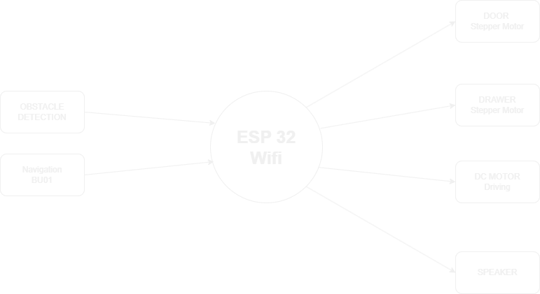
| Microcontroller | ESP32 |
| Tabletop Device | ESP8266/ESP32,Touchscreen Display, QR Code Generator(optional) |
| Motion Control | DC Motors, Motor Driver, Wheels, Chassis |
| Inertial Navigation | IMU Sensor, Magnetometer (Optional) |
| Line-Following | TCRT5000 IR Sensors, LED Indicators |
| Obstacle Avoidance | Ultrasonic Sensor, Buzzer/Speaker |
| Voice Interaction | Microphone, Speaker |
| Power Supply | LiPo/Li-ion Battery, Voltage Regulator, Charging Dock |
| Additional Components | LCD/OLED Display, Servo Motors, Weight Sensor (Optional) |
Scope for improvement
1. Tabletop Device for Ordering and Paying
The tabletop device at each table can be upgraded to allow customers to order food and pay directly from their seats. Customers can browse the menu, select their meals, and complete the payment using a QR code displayed on the device. This eliminates the need to wait in line or interact with staff, making the process faster and more convenient. Orders are sent directly to the kitchen and the robot, ensuring quick preparation and delivery. This feature not only saves time but also enhances the overall dining experience by making it more interactive and user-friendly.
2. Advanced Navigation System
The robot’s navigation system can be upgraded from a simple line-following method to a more advanced system. Instead of relying on lines marked on the floor, the robot can use sensors and mapping technology to move around freely. This allows it to avoid obstacles, find the best path, and navigate complex cafeteria layouts with ease. With this improvement, the robot becomes more flexible and reliable, even in busy or crowded environments. It can handle unexpected challenges, such as people standing in its way or changes in the cafeteria layout, ensuring it always reaches its destination.
3. Voice Interaction
Adding voice interaction to the robot makes it more engaging and user-friendly. Customers can give voice commands, such as “Robot, clean Table 5” or “Bring my order to Table 3,” and the robot can respond with voice feedback like “Your food is on its way!” or “Please place your trash here.” This feature makes the robot feel more personal and approachable, enhancing the overall dining experience. Voice interaction also makes the robot accessible to everyone, including those who may not be comfortable using touchscreens or buttons.
Flow Chart
Bill of Materials
| Item | Quantity | |
|---|---|---|
| 1 | Stepper motor | 4 |
| 2 | ESP32 | 1 |
| 3 | Servo | 2 |
| 4 | NeoPixel LED | 1 strip |
| 5 | Horn | 1 |
| 6 | Foam Box | 1 |
| 7 | UWB | 1 |
These were my initial plans for the project. Over time, I refined and reimagined the concept, eventually deciding to build an indoor office robot designed to deliver materials within an office environment. This direction was chosen because it was practical, easier to implement within the limited time frame, and allowed for smoother integration of available resources. The project was then updated, redefined, and fully planned out in the following weeks.
Starting the project
Project Inspiration, References & Resources
Several existing projects inspired my work, although none were exactly the same as mine. Many robots have been designed for delivering food and drinks in restaurants and hotels, but my goal was to create a simpler, compact delivery robot tailored specifically for office environments. One of the primary sources of inspiration was Pudu Robotics, a company known for developing beautifully designed and highly practical service robots for commercial spaces like restaurants and hotels. Their attention to design aesthetics and user experience influenced the form factor of my own robot.
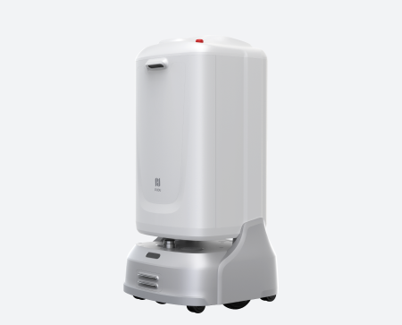
Image Source: Pudu Robotics
Another major inspiration came from Starship Deliveries, which developed autonomous outdoor delivery robots. Their design struck me as both practical and aesthetically refined, and it motivated me to focus on clean visual styling and modular construction in my own indoor robot project.
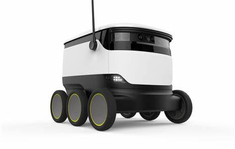
Image Source: Starship Deliveries
Design Overview
This section showcases the design development of the robot, highlighting the integration of 3D printed parts, molded components, laser-cut acrylic, and a CNC-routed wooden base. Most of the mechanical components, such as the wheels and mounts, were custom-designed and fabricated in the Fab Lab using accessible digital fabrication techniques.
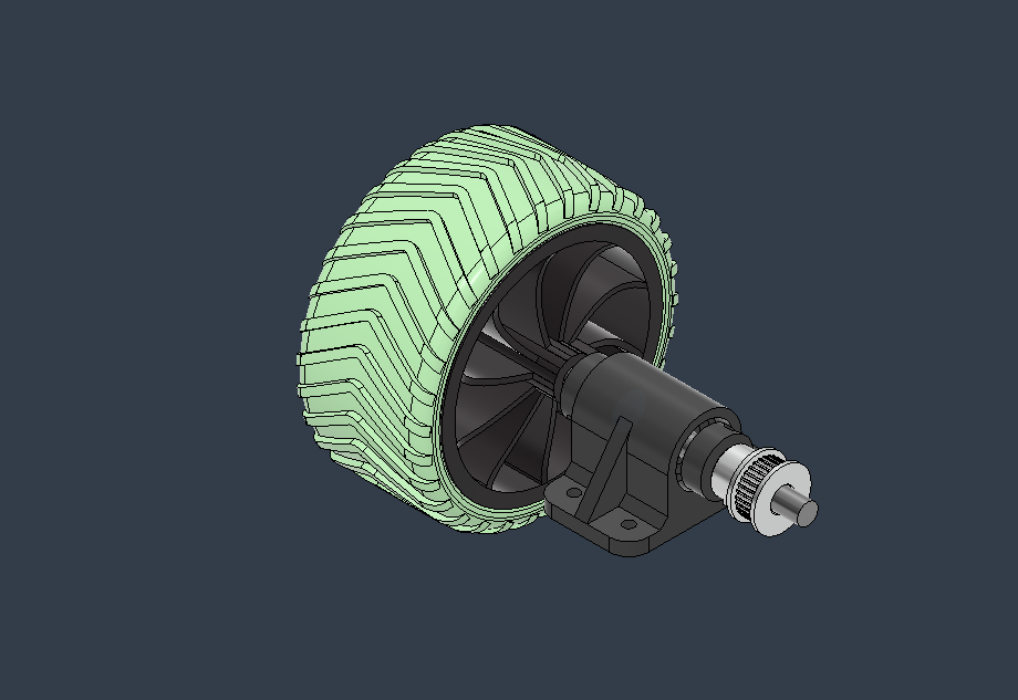
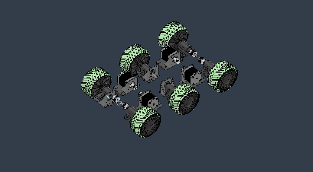
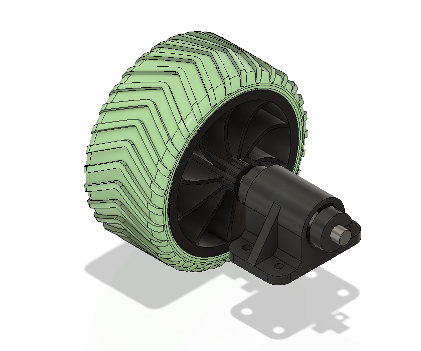
The wheel assembly was custom-designed in Fusion 360. Most parts, including the hub and stopper, were 3D printed using PLA, while the outer gripping surface of the wheel was created using a mold and casted with rubber-like PU resin. The 3D printed stoppers were used to secure the wheels to the shaft and prevent any slippage during motion.
This image shows the planned placement of the wheels and stepper motors on the wooden base. Each side of the robot features a pair of stepper motors, which are aligned to ensure smooth and balanced movement.
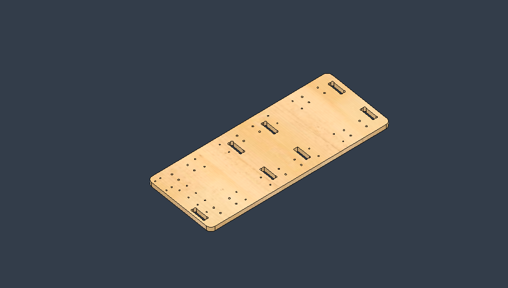
The wooden base of the robot was designed to accommodate all essential drive components. It was CNC routed to include slots and holes for mounting motors, bearings, shafts, and other hardware. The use of a 12mm plywood sheet provided a sturdy and reliable foundation.
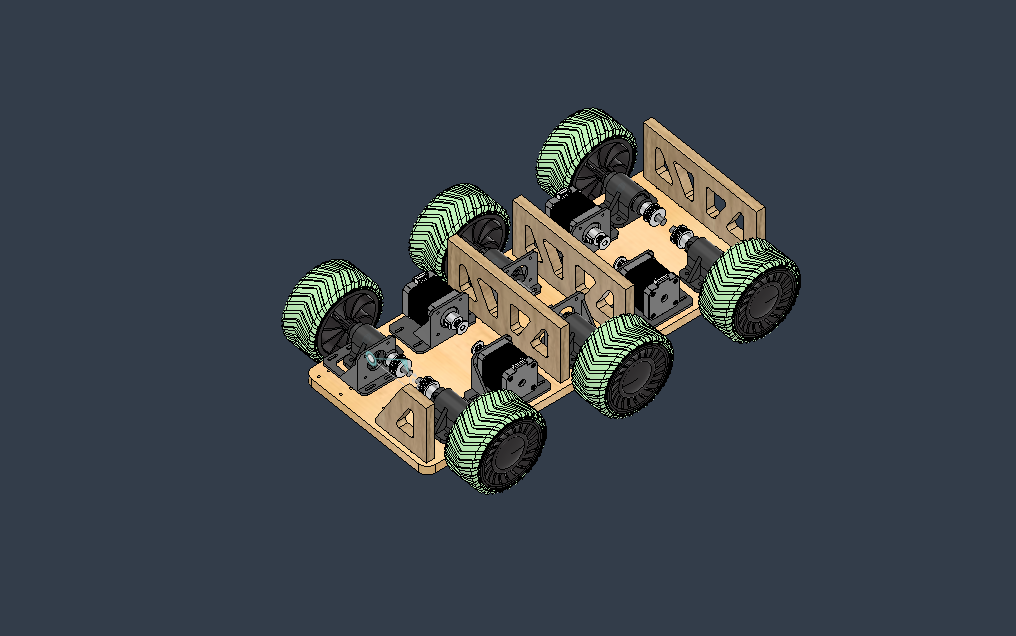
This image shows the assembled driving platform, including the wooden base and the vertical structural ribs. These ribs provide support for the upper acrylic and 3D printed sections of the robot’s body, ensuring rigidity and alignment.
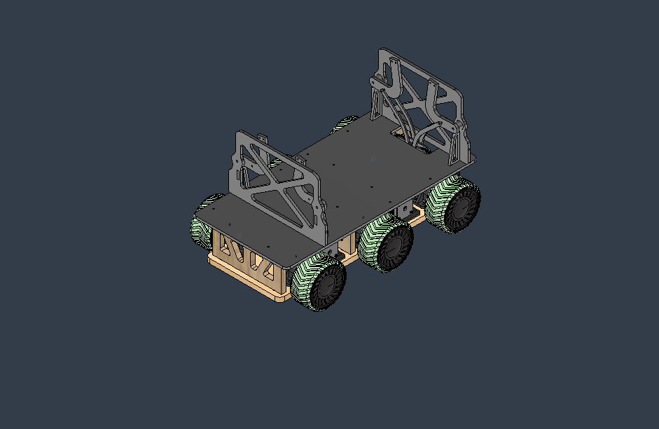
The front-facing structural plate was laser cut from acrylic. This section supports the door mechanism, electronics, and forms the interface between the drive base and the rest of the robot’s body. It also helps hold the 3D printed upper structure firmly in place.
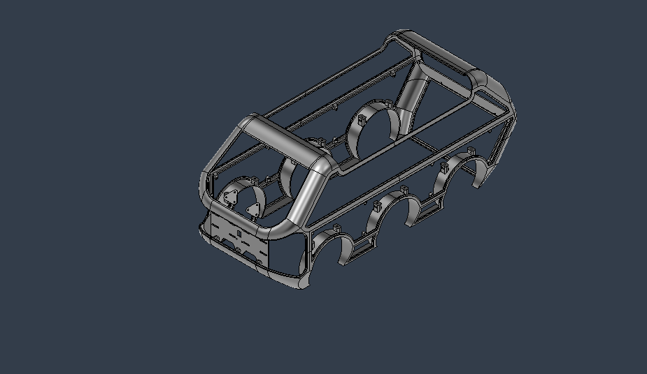
The main body shell of the robot was 3D modeled to be printed in multiple parts. This shell acts as the external frame, onto which the laser-cut acrylic panels are mounted. Once printed, the body sections were joined using adhesive. The design was split into two major parts—upper and lower—for easier printing and assembly.
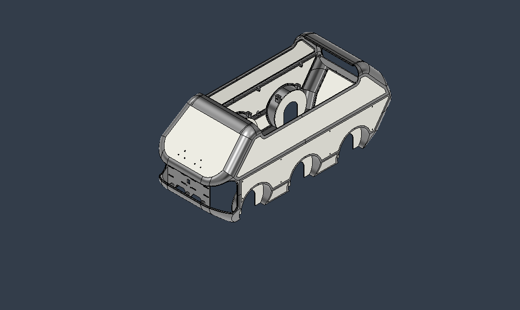
This image illustrates how flat acrylic panels were integrated with the 3D printed frame to complete the outer shell of the robot. This hybrid approach helped reduce both material cost and production time, while still maintaining a clean and professional aesthetic.
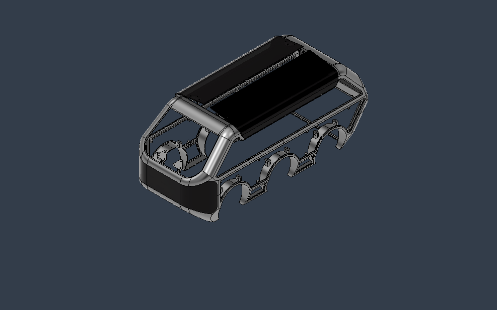
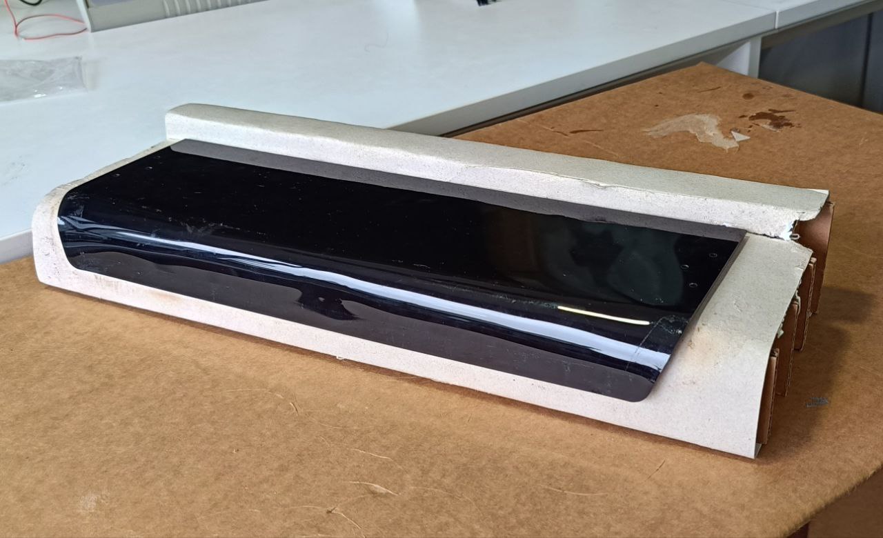
Some curved sections of the robot body, such as the front door and hood, were created using heated and bent acrylic sheets. For visual appeal and partial transparency, smoke-tinted acrylic was used. These parts were shaped using custom jigs and carefully applied heat.
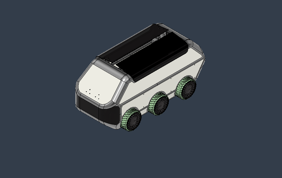
Finally, this image shows the fully assembled robot body. All 3D printed components, acrylic panels (both flat and bent), and mounting structures were combined to complete the outer shell. At this stage, the body was ready for painting and mounting onto the mechanical base.
Tyre molding
For my project, I needed to use multiple tyres. I had two options: either purchase tyres from the market or design and manufacture custom tyres that suited my specific needs. After evaluating both options, I decided to design a custom tyre tailored to my project requirements.
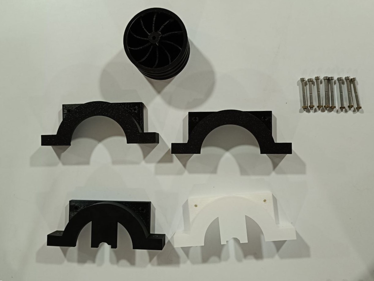
I started by designing the tyre in Fusion 360. The central section of the tyre was 3D printed using PLA material. To create the actual tyre body, I chose to use a molding process. For this, I also designed a 3D printed mold. The mold consisted of four individual parts that could be assembled using screws.
After printing and assembling the mold, I tested it for leakage by filling the mold cavity with water. Unfortunately, the mold leaked due to gaps between the parts. To fix this, I applied a seal using double-sided tape, which significantly improved the results and stopped the leakage.
The next challenge was choosing a suitable material for the tyre itself. After some research, I selected a rubber-like polyurethane (PU) resin, which was flexible and ideal for my application. Before pouring the resin, I applied a generous amount of mold release agent to ensure the tyre could be easily removed after curing. For aesthetic appeal, I added green pigment to the resin mixture.
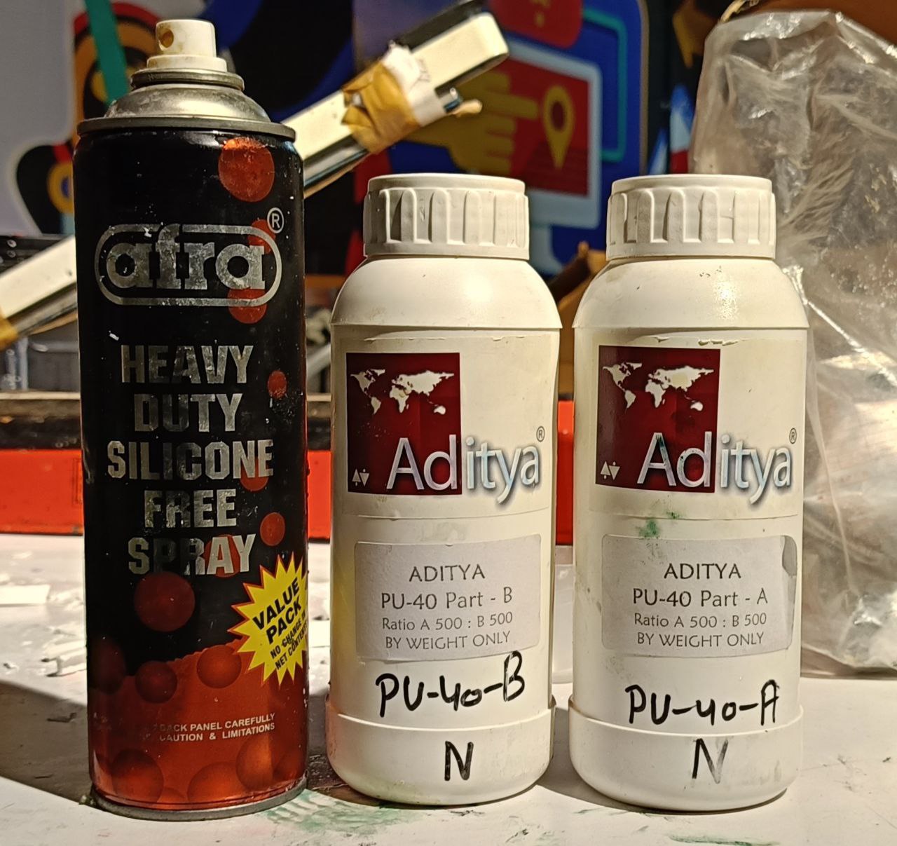
The PU resin required a 1:1 mixing ratio of resin and hardener. The pigment was mixed thoroughly into the resin to achieve uniform color. To minimize air bubbles, I initially tried using a vacuum pump, but this led to excessive bubbling due to the nature of the resin. Instead, I carefully stirred the resin and avoided using the vacuum chamber.
To inject the resin into the mold accurately, I used a syringe, which allowed me to direct the flow of the resin effectively. The process had to be completed quickly before the resin9 began to harden. The curing time for the resin was approximately 12 hours to ensure it fully set.
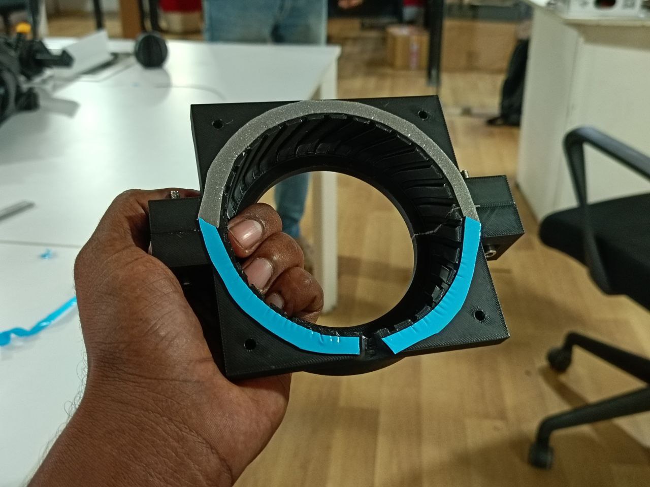
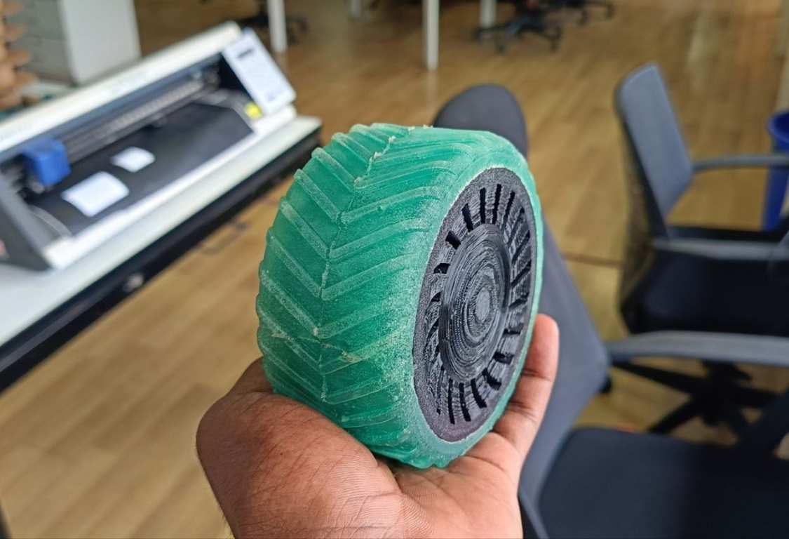
After curing, removing the mold was a bit challenging due to the intricate thread pattern on the tyre. Despite some remaining air bubbles in the final product, the first attempt was quite successful and yielded promising results for further development.
Acrylic Bending
For my project, I needed some curved parts, and some of these parts had to be transparent. My first option was to heat acrylic sheets and bend them into the desired shapes.
To ensure precise and consistent bends, I started by designing a jig in Fusion 360. The jig was created to match the exact dimensions of the acrylic sheet and help guide the bending process accurately.
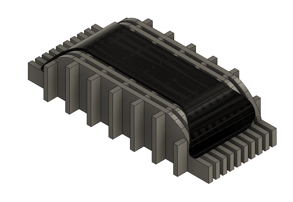
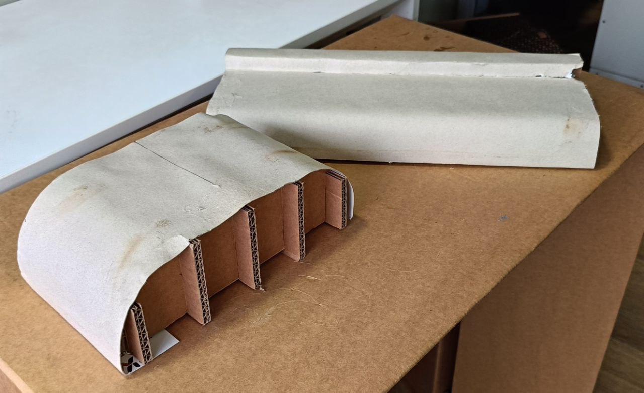
I made the jig using cardboard sheets, which I cut using the Zund machine for high precision. To achieve a clean surface finish on the bent acrylic, I covered the jig with a layer of smooth paper. This prevented imperfections or surface marks from appearing on the acrylic after heating.
After cutting all the cardboard pieces, I assembled the jig and glued the paper layer onto the surface where the acrylic sheet would rest. I used hot glue to attach the paper, making sure that the surface was smooth and free from bumps or wrinkles. Any irregularities could transfer onto the softened acrylic, ruining the final appearance.
Once the jig was ready, I used a heat gun to evenly heat the acrylic sheet until it became flexible. I then placed the heated acrylic over the jig and applied gentle pressure to shape it according to the curve. Before heating, I used masking tape to fix the acrylic sheet in the correct position by taping the sides and ends. This helped ensure proper alignment and control during the bending process.
As the acrylic softened, I used the taped edges to guide and press it into place. Once it was properly bent and positioned over the jig, I allowed it to cool and set in the desired shape. This method worked effectively to produce clean, accurately curved transparent parts.
Door Mechanism
The door mechanism is a crucial part of my project. I designed it in such a way that the door opens fully, allowing easy access to the materials stored inside the container. The mechanism needed to operate smoothly and efficiently, enabling the door to open and close without any obstruction.
To achieve this, I chose a geared mechanism driven by a single stepper motor. This setup is simple, reliable, and provides the torque and precision required for smooth operation. Additionally, I wanted the mechanism to be easy to manufacture and replicate, so I selected acrylic as the primary material. Acrylic is easy to cut using a laser cutter and provides the structural strength needed for this application.
I designed the entire mechanism in Fusion 360, where I defined all the joints and tested the movement virtually to ensure that it functioned correctly. This step was essential to verify the concept before moving to physical prototyping.
Before committing to the final build, I conducted a few test cuts to check the overall mechanism design, bearing placement, and fitment of parts. These tests helped me fine-tune the tolerances and confirm that the components would fit together as intended.
The design included load-bearing rotating components mounted through bearings using screws. All sides and structural parts of the mechanism were made from laser-cut acrylic sheets, making the entire assembly easy to fabricate and replicate.
Once the design was finalized, I laser-cut all the acrylic parts and assembled them to create the final mechanism. The gear that connects the stepper motor to the rest of the mechanism was 3D printed for better customization and fit.
After assembling all the components, I tested the complete mechanism. It worked very well, with smooth operation. There was a slight amount of backlash, which was expected due to the clearance (offset) I intentionally included to ensure the gears meshed and rotated smoothly without binding.
Overall, the mechanism performed as expected during testing. It met the design goals and proved to be a reliable and easy-to-manufacture solution for the door operation in my project.
Electronics
My robot consists of multiple electronic boards. One board is dedicated to controlling the motors that drive the robot's wheels and the door mechanism. Another board is used to control all the LEDs on the robot. The main board houses the primary microcontroller, which handles communication between the other boards as well as with the external controller.
I started by designing the motor control board.
Motor Board
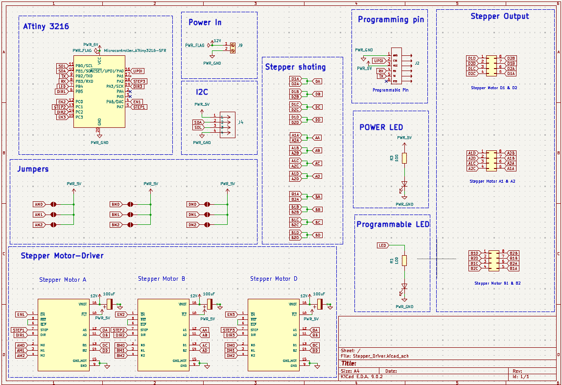
Board A
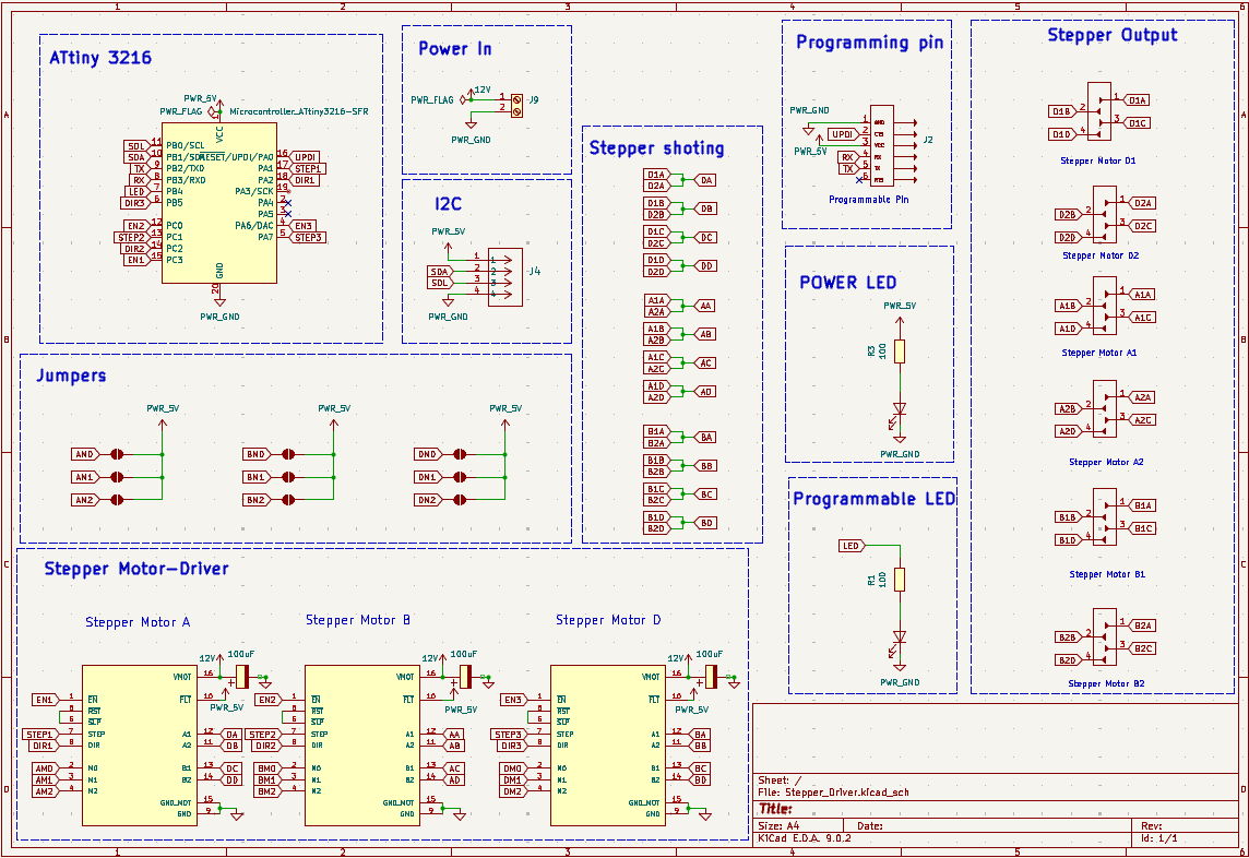
This board is used to control the motors of the robot. The brain of the motor driver board is an ATtiny3216 microcontroller, which communicates with other boards using the I2C protocol. The board is designed to support up to three DRV8825 stepper motor drivers. Each driver can control two stepper motors. Since each side of the robot has two stepper motors for driving, motors on the same side are connected to a single driver. The third driver is used to control the door mechanism.
Below is the schematic of the board:
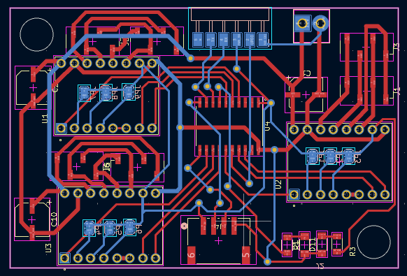
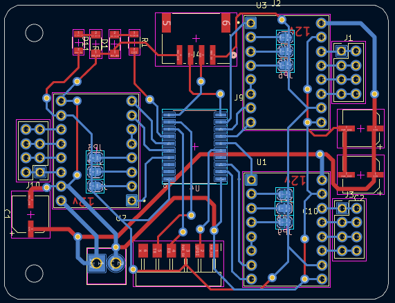
This is the board layout, which is a double-layer PCB:
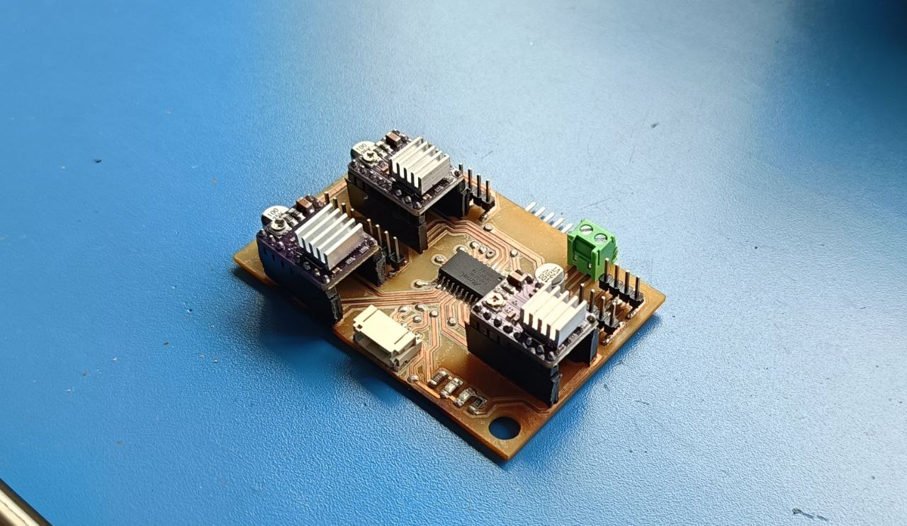
This is the final PCB after assembly:
Board B
While designing Board A, I faced issues with tracks on both sides of the PCB, which made soldering difficult. As a result, I had to redesign, remill, and reassemble everything again.
The schematic of Board B is shown below. There were only minor changes from the previous version, mainly related to the pin assignments:
This version is also a double-layer PCB. I corrected the earlier issues by changing all header pins to through-hole (THC) types. This prevents the tracks from peeling off during component removal. I also rerouted some signal stacks to one side of the board to simplify soldering.
Additionally, I managed to reduce the board size in this revision.
Here are the updated tracks of the board:
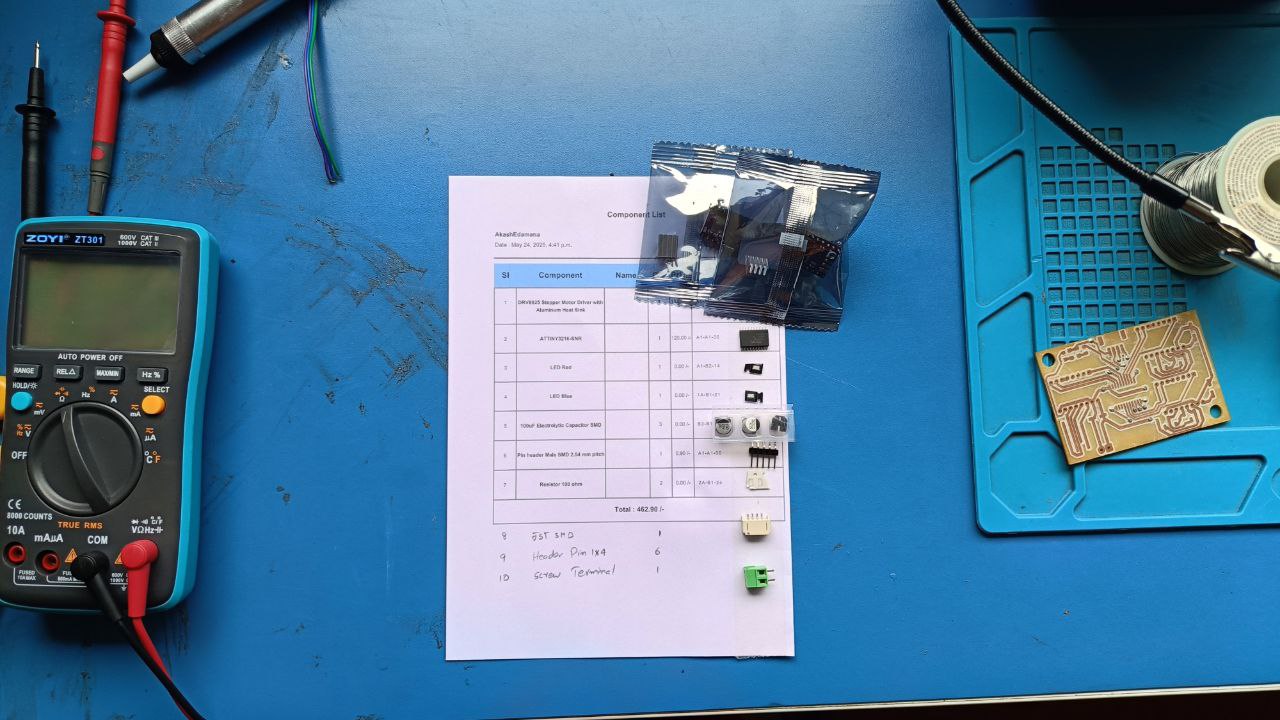
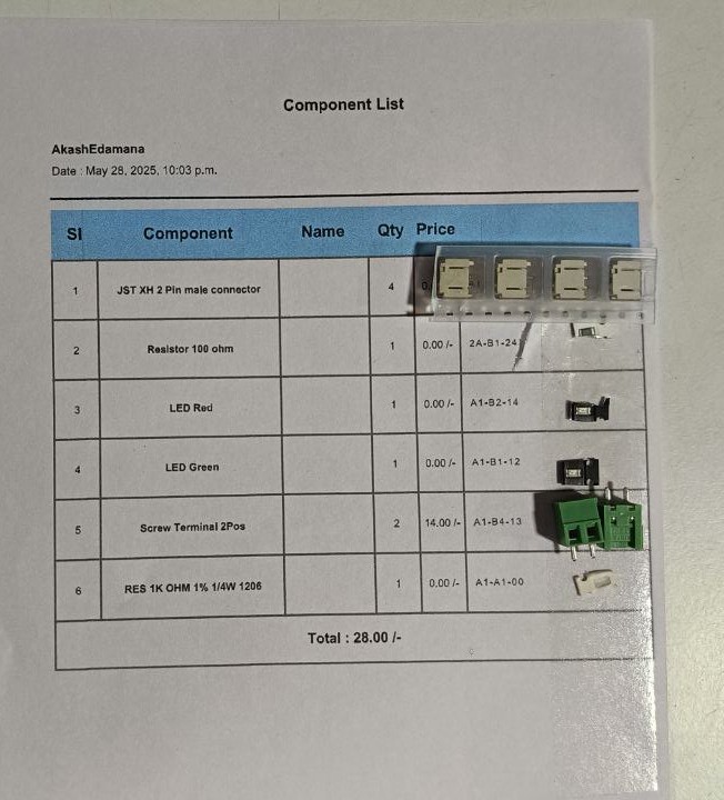
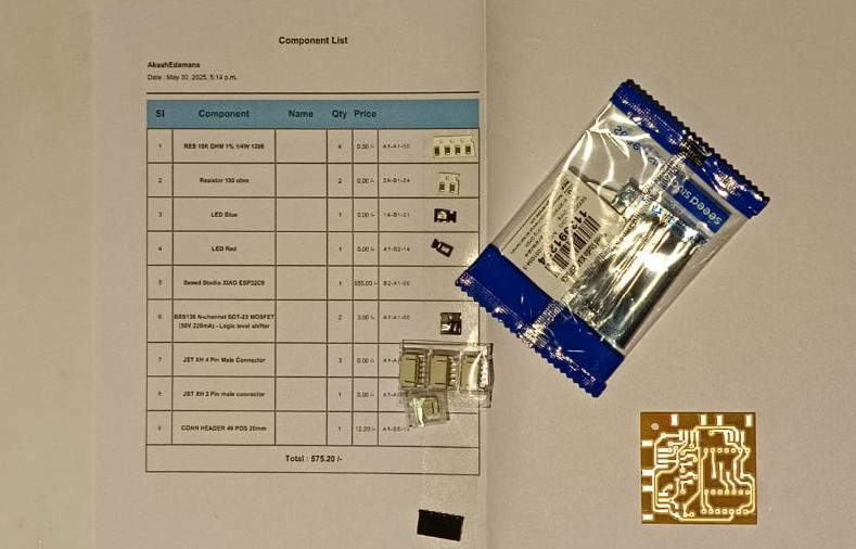
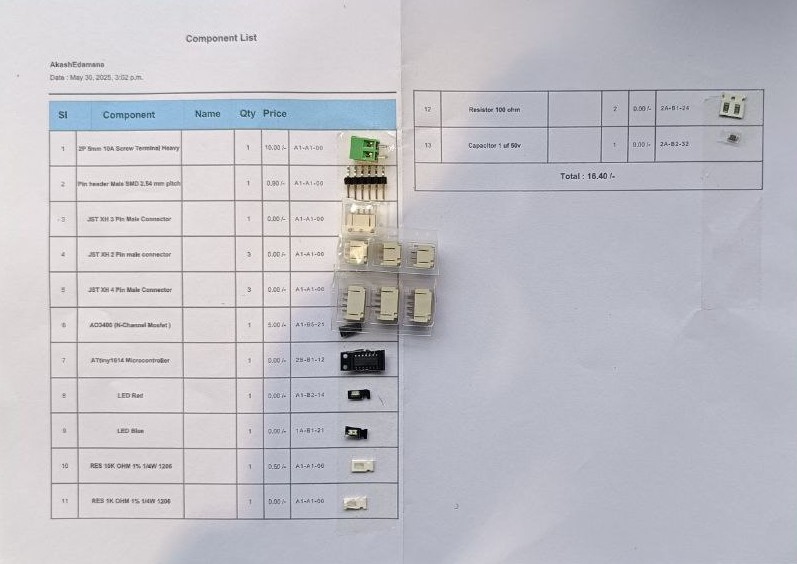
These are all the components required for assembling the board:
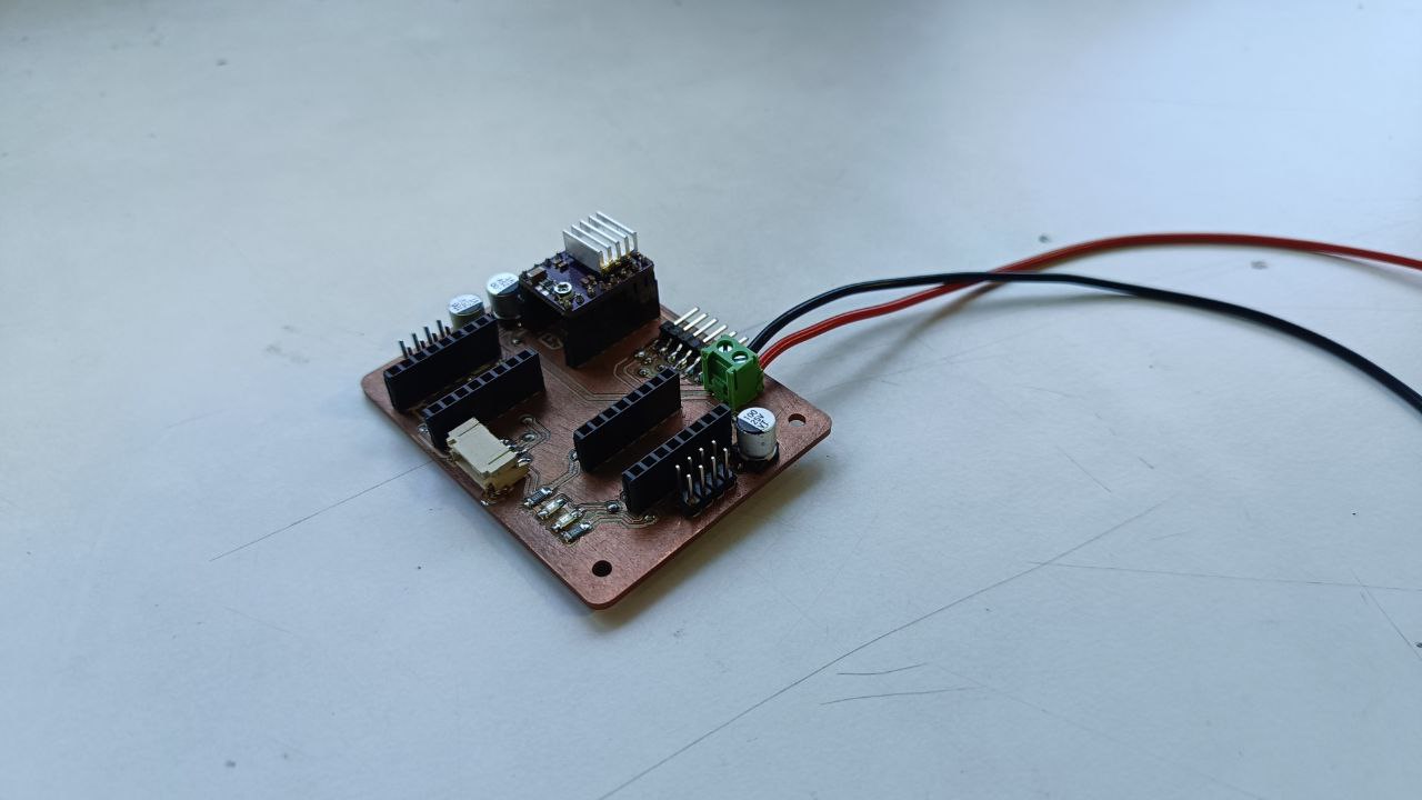
This is the final PCB after assembly:
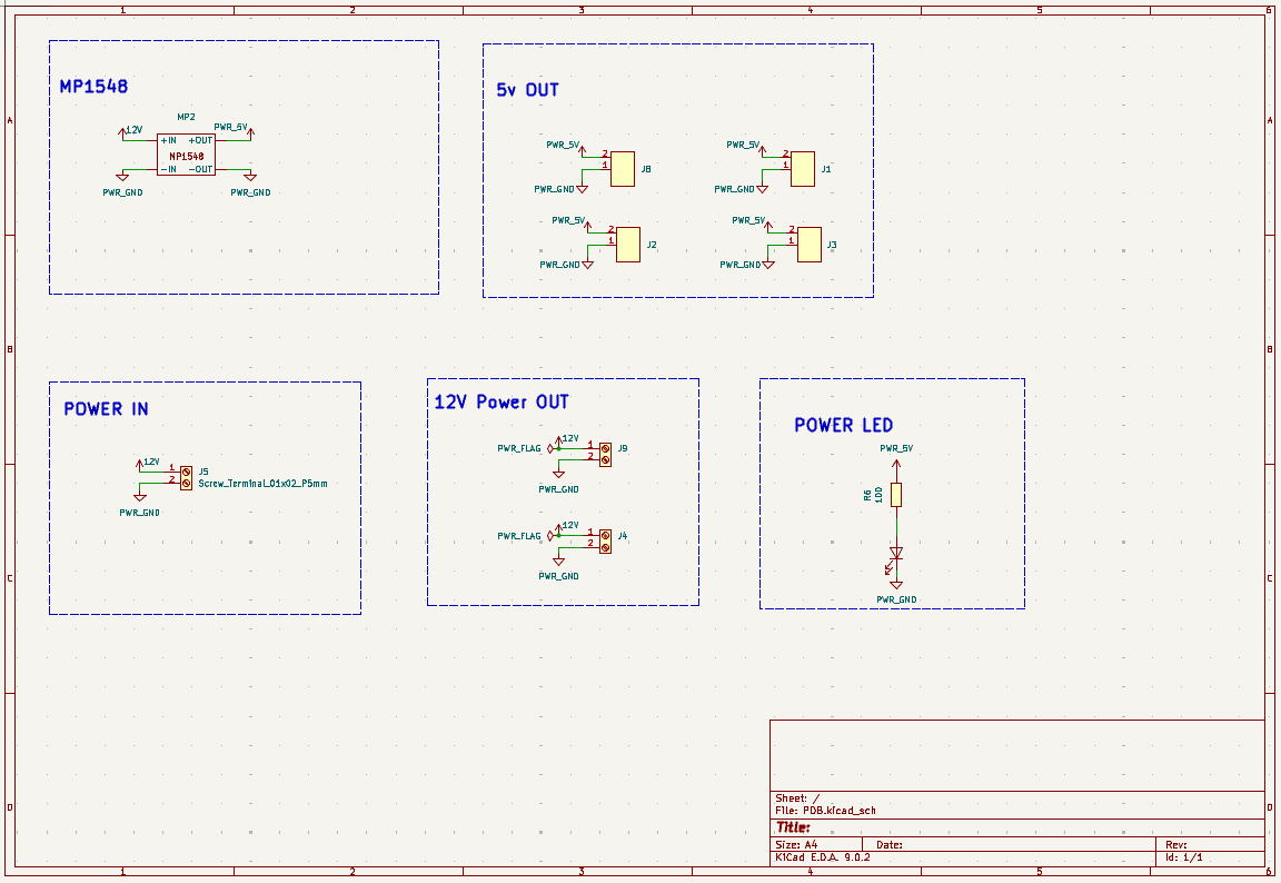
PDB
The Power Distribution Board (PDB) is designed to supply power to all components of the robot. It is a simple yet essential board that connects the battery to the main control board and the LED board.
This board includes a power buck converter that takes an input of 12V and steps it down to 5V. It provides multiple output terminals for both 12V and 5V, allowing various components to be powered efficiently and safely.
Below is the schematic of the Power Distribution Board:
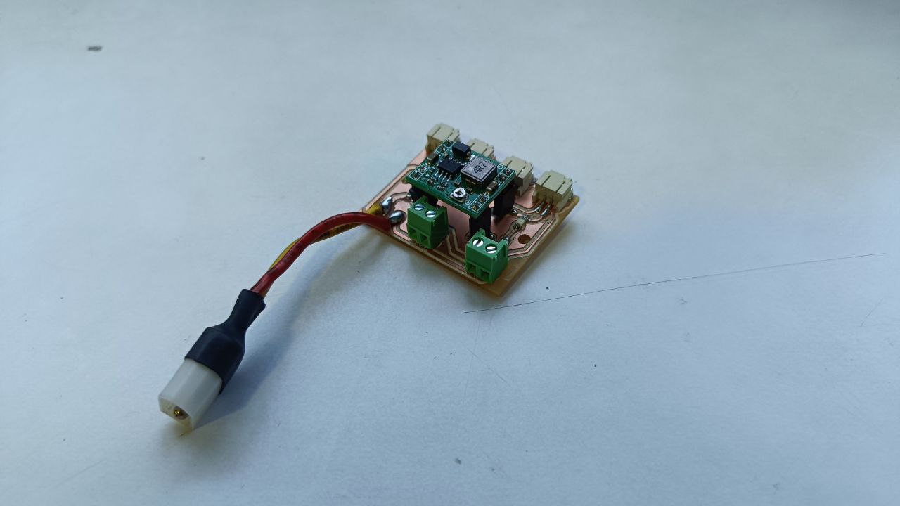
This is the final assembled board. An XT60 connector was custom-designed and 3D printed to securely connect the battery to the PDB.
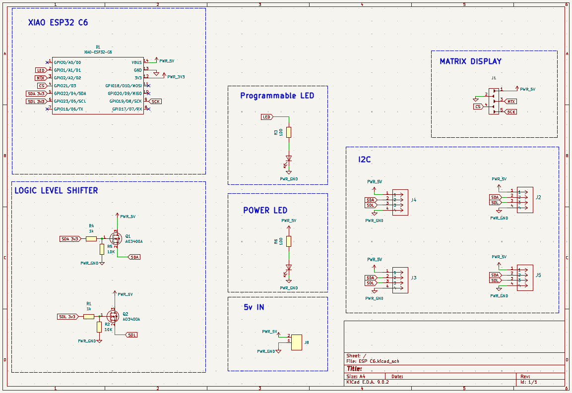
Main Board
This is the main board of the robot, and it handles communication between the robot and my computer. The board is built around a XIAO ESP32-C6 microcontroller. Since the ESP32 operates on 3.3V logic, a logic level shifter circuit is included on the board to safely convert 5V signals to 3.3V.
The board includes multiple I2C ports, allowing other boards (like the motor and LED boards) to communicate with it. Additionally, it features ports to connect a matrix LED display and a 9-axis gyroscope sensor. The design is compact and optimized for easy assembly and integration into the robot.
Below is the schematic of the main board:
This is the PCB layout (trace view) of the board:
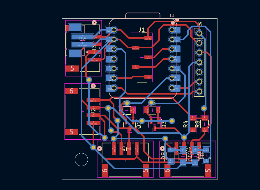
Here are images of the board after assembly:
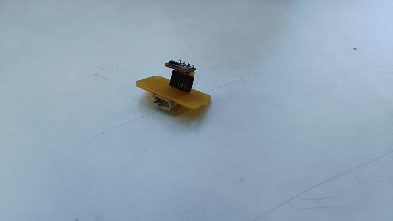
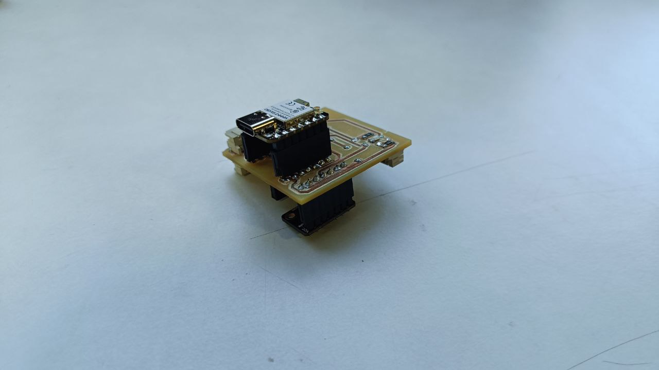
There were some issues with this board even after all components were connected and tested. The main problem was with soldering the XIAO ESP32-C6 module. Since some of its pins are located on the underside and others on the top, it made proper soldering difficult, which resulted in unexpected behavior during testing.
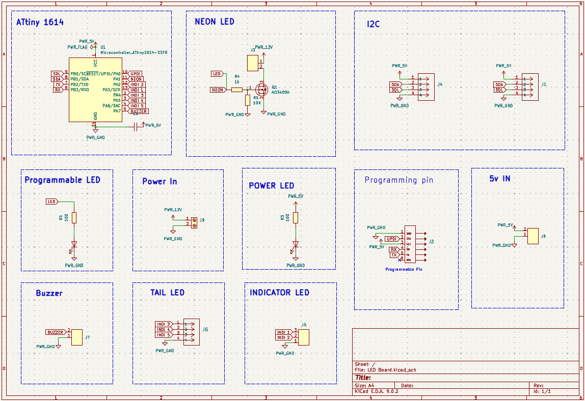
LED Board
This board controls all the LEDs in the robot. It operates using a 12V input, which is required to power the neon LED strip. Additionally, it provides a separate 12V input for other LEDs in the system.
Since I needed to control a NeoPixel LED strip, I had to make some modifications to the board after it was milled to ensure compatibility. The board is powered by an ATtiny1614 microcontroller, which serves as its brain and handles LED control logic.
Below is the schematic of the LED board:
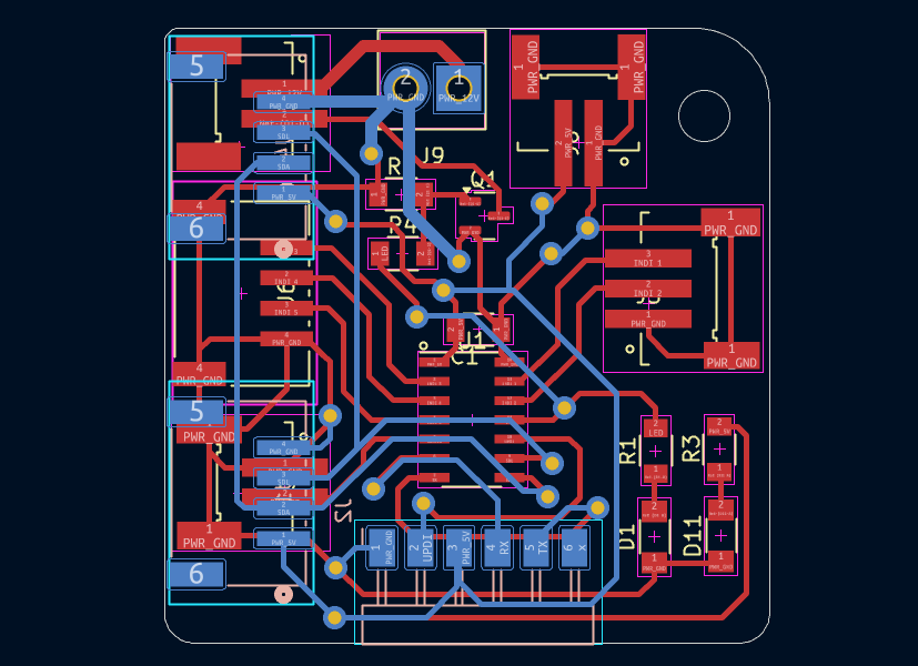
This is the PCB layout (trace view) of the board:
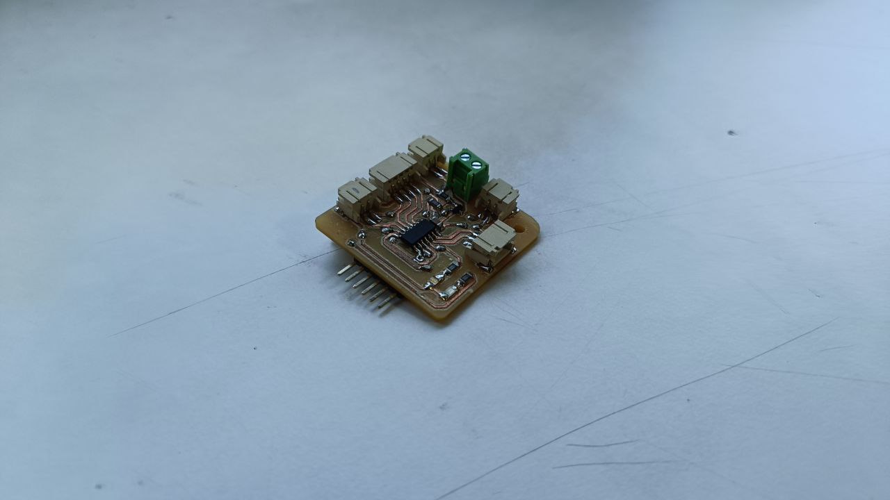
Here is the image of the board after assembly:
The board also includes I2C pins for communication with the main controller and JST connectors for easily attaching LED components.
Base Routing and Assembly
The base of the robot is made from a single piece of 12 mm thick wood, which was routed using a CNC machine. The routing process involved cutting precise grooves and slots to mount various components while maintaining the structural integrity of the robot. The design also includes support ribs to hold the top plate in place.
For routing the wooden base, I used the Zund machine. I designed the layout in Fusion 360 and exported it as an SVG file, which was then used with the Zund machine to perform the routing.
Once the wooden base was routed, all the necessary components—most of which were already 3D printed—were ready to be assembled. On the routed base, I mounted the wheels, wheel hubs, stepper motors, and belts. These components were then tensioned and properly assembled.
Below is the final result after the base was completely assembled:
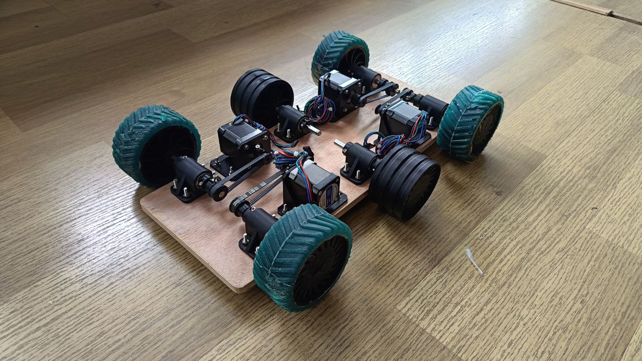
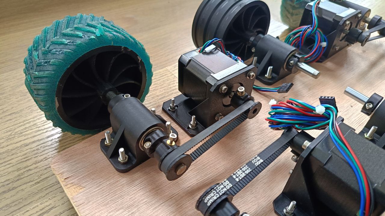
This image shows the basic drive setup. The wheels are connected to a 3D printed base. Inside the base, bearings are used to hold a stainless steel shaft in place. To prevent the wheels from slipping or coming off, 3D printed stoppers are added. A 3D printed clamp supports the stepper motors and includes pill-shaped slots for screws, allowing for adjustable spacing between the motor and wheel assembly. This adjustability helps set the correct belt tension. The stepper motors are mounted to the base using custom 3D printed brackets.
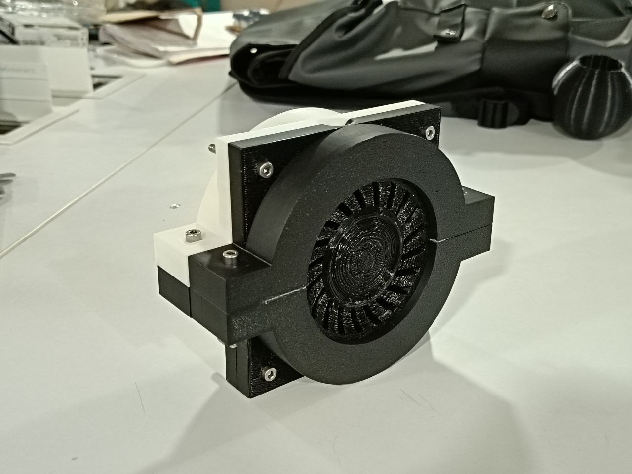
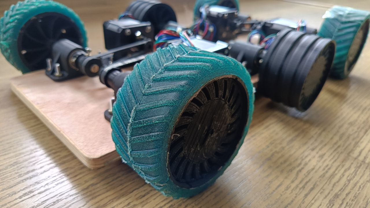
Below is an image showing how the tyre looks after it is completely assembled and attached to the robot:
Body Assembly
The body of the robot is made using a combination of 3D printing and acrylic sheets. To reduce production costs, all flat surfaces were made from acrylic, while the curved and complex parts were 3D printed. This hybrid approach helped maintain strength and appearance while being cost-efficient.
Some of the curved parts, such as the door and front panel, were created by heating and bending acrylic to achieve a smooth, aesthetic shape.
Since the body is quite large, it was split into multiple parts to make 3D printing more manageable and reduce overall print time. All the flat and small parts were made from laser-cut acrylic, which significantly helped lower production time and cost.
The 3D printed and acrylic parts were assembled using super glue. However, the central acrylic piece was assembled using screws, as it plays a crucial role in holding both the top and bottom sections of the robot body together.
This is the final look of the robot body after full assembly. The combination of acrylic and 3D printed parts gave it a clean and functional appearance.
If more time had been available, additional body components could have been made using bent acrylic. This would have further reduced both production cost and time, while also enhancing the aesthetic appeal of the robot.
Assembly
The assembly process was a crucial step in the development of the robot. It was during this phase that small issues were identified and resolved. The first step in the assembly was completing the base, which had already been routed and assembled earlier. The next phase involved manufacturing and assembling the remaining body parts—most of which were created using laser cutting.
This stage also included assembling the door mechanism and conducting initial functionality tests to ensure smooth operation.
Since the electronic boards had already been assembled, I proceeded to mount them onto the frame. The front and side acrylic panels were then attached to form the body structure.
After completing the main structural assembly, I moved on to assembling and testing the electronics. This included connecting the power lines, motors, sensors, and verifying I2C communication between the boards.
Finally, the doors were manually assembled and tested to ensure proper opening and closing using the stepper-based door mechanism.
Wiring
The wiring process was a critical step in assembling the robot. It involved connecting all the electronic components, including the motors, sensors, LED boards, and display, to ensure the entire system functioned correctly.
First, all components were loosely assembled and tested to verify individual functionality before the final wiring.
The first stage of wiring involved connecting the stepper motors. Since there are multiple stepper motors, cable management was essential. I used zip ties to organize the wires neatly and routed them through the bottom layer of the robot. The cables were then directed to the front where they connect to the motor board.
The matrix LED display was also assembled and tested at this stage to ensure all the connections were properly made and functioning.
Next, the motor board and LED board were assembled and connected. These were carefully positioned to ensure a secure fit within the frame. The Power Distribution Board (PDB) was also installed and wired to deliver power to all components.
The main board was then connected to the PDB, motor board, and LED board. Additional connections were made to the matrix display and the 9-axis gyroscope sensor. All connections were double-checked to ensure proper power and communication lines, and to confirm that everything fit well inside the body of the robot.
The final step involved testing all components. The matrix LED display was fully tested, and the I2C communication between all boards was verified to ensure seamless integration across the system.
Programming
Motor Testing
Motor Control Code Documentation
1. LED and Motor Pin Definitions
#define LED 5

#define Step1 3
#define Dir1 4
#define En1 2
These lines define the control pins:
LED: Used for visual status indication (pin 5).Step1,Dir1,En1: Pins for controlling Motor Driver 1 (DRV8825).
2. Motor Driver Setup
void setup() {
  pinMode(LED, OUTPUT);
  pinMode(Step1, OUTPUT);
  pinMode(Dir1, OUTPUT);
  pinMode(En1, OUTPUT);
  digitalWrite(En1, LOW);
}
Initializes the LED and motor control pins:
pinMode(...): Sets pins as outputs.digitalWrite(En1, LOW): Enables the motor driver (LOW = enabled for DRV8825).
3. Main Loop: Forward and Reverse Motion
void loop() {
  digitalWrite(LED, HIGH);
  digitalWrite(Dir1, HIGH);
  for (int i = 0; i < 7500; i++) {
    stepAllMotors();
  }

  delay(1000);

  digitalWrite(LED, LOW);
  digitalWrite(Dir1, LOW);
  for (int i = 0; i < 7500; i++) {
    stepAllMotors();
  }

  delay(1000);
}
This function runs repeatedly:
- Turns on LED and moves the motor forward 7500 steps.
- Turns off LED and moves the motor in reverse 7500 steps.
delay(1000): Pauses for 1 second between directions.
4. Step Function
void stepAllMotors() {
  digitalWrite(Step1, HIGH);
  delayMicroseconds(STEP_DELAY);
  digitalWrite(Step1, LOW);
  delayMicroseconds(STEP_DELAY);
}
Sends a single step pulse to the motor:
digitalWrite(Step1, HIGH)followed byLOW: creates one step pulse.delayMicroseconds(STEP_DELAY): Controls step speed with a defined delay.
Simplified Concept
// Set direction and move motor forward
digitalWrite(Dir1, HIGH);
for (int i = 0; i < steps; i++) {
  digitalWrite(Step1, HIGH);
  delayMicroseconds(50);
  digitalWrite(Step1, LOW);
  delayMicroseconds(50);
}
This is a minimal version of motor control: set direction, pulse the step pin repeatedly to move the motor.
Code :Door_Motor_Test.ino
LED & Neon Animation Code
LED Control Board Documentation
1. Pin and LED Configuration
#define Neo_Pix_Pin 2
#define Neon_pin    8
#define Num_LED     14
#define I2C_ADDRESS 0x09
Defines hardware connections and I2C address:
Neo_Pix_Pin: Pin connected to the NeoPixel strip.Neon_pin: Digital pin for controlling the neon LED.Num_LED: Total number of NeoPixels.I2C_ADDRESS: I2C slave address for this board.
2. Setup Function
void setup() {
  strip.begin();
  strip.setBrightness(50);
  strip.show();

  pinMode(Neon_pin, OUTPUT);
  digitalWrite(Neon_pin, HIGH);

  Serial.begin(9600);
  Wire.begin(I2C_ADDRESS);
  Wire.onReceive(receiveEvent);
}
Initializes LED strip, neon pin, serial, and I2C communication.
strip.begin(): Initializes the NeoPixel library.Wire.onReceive(receiveEvent): Registers callback for I2C commands.
3. Loop Function
void loop() {
  if (!greenBlinking && !leftAnimating && !rightAnimating && !reverseAnimating) {
    for (int i = 0; i < Num_LED; i++) strip.setPixelColor(i, strip.Color(255, 0, 0));
    strip.show();
  }

  if (neonBlinking) handleNeonBlink();
  if (greenBlinking) handleGreenBlink();
  if (rightAnimating) handleRightAnimation();
  if (leftAnimating) handleLeftAnimation();
  if (reverseAnimating) handleReverseAnimation();
}
Controls default red state and calls active animation handlers.
4. I2C Command Handler
void receiveEvent(int howMany) {
  char cmd = Wire.read();
  switch (cmd) {
    case 'L': ... break;
    case 'R': ... break;
    case 'B': ... break;
    case 'O':
    case 'C': ... break;
  }
}
Responds to incoming I2C commands:
'L': Start left turn signal animation.'R': Start right turn signal animation.'B': Trigger reverse light animation.'O','C': Trigger neon blink and green blinking animation.
5. Neon Blink Handler
void handleNeonBlink() {
  if (millis() - neonLastBlinkTime >= BlinkInterval) {
    neonState = !neonState;
    digitalWrite(Neon_pin, neonState ? HIGH : LOW);
    if (!neonState) neonBlinkCount++;
    if (neonBlinkCount >= 10) {
      neonBlinking = false;
      digitalWrite(Neon_pin, HIGH);
    }
  }
}
Toggles the neon LED on and off 10 times, then leaves it ON.
6. Green Blink Handler
void handleGreenBlink() {
  if (millis() - greenLastBlinkTime >= BlinkInterval) {
    greenState = !greenState;
    for (int i = 0; i < Num_LED; i++)
      strip.setPixelColor(i, greenState ? strip.Color(0, 255, 0) : strip.Color(255, 0, 0));
    strip.show();
  }
  if (millis() - greenStartTime >= GreenBlinkTime) {
    greenBlinking = false;
    for (int i = 0; i < Num_LED; i++)
      strip.setPixelColor(i, strip.Color(255, 0, 0));
    strip.show();
  }
}
Flashes all LEDs green for 6 seconds before reverting to red.
7. Left Turn Animation
void handleLeftAnimation() {
  for (int i = 0; i <= 6; i++) {
    int distance = abs(i - leftStep);
    int brightness = max(0, 255 - distance * 60);
    strip.setPixelColor(i, strip.Color(brightness, brightness / 2, 0));
  }
  ...
}
Sweeps amber light from left side LEDs repeatedly.
8. Right Turn Animation
void handleRightAnimation() {
  for (int i = 13; i >= 7; i--) {
    int distance = abs(i - (13 - rightStep));
    int brightness = max(0, 255 - distance * 60);
    strip.setPixelColor(i, strip.Color(brightness, brightness / 2, 0));
  }
  ...
}
Sweeps amber light from right side LEDs repeatedly.
9. Reverse Animation
void handleReverseAnimation() {
  int center1 = 6;
  int center2 = 7;
  for (int i = 0; i <= reverseStep; i++) {
    int brightness = constrain(i * 40, 0, 255);
    if (center1 - i >= 0) strip.setPixelColor(center1 - i, strip.Color(0, 0, brightness));
    if (center2 + i < Num_LED) strip.setPixelColor(center2 + i, strip.Color(0, 0, brightness));
  }
  ...
}
Expands blue glow from the center outward, used for reverse indication.
Code : LED_Final.ino
Motor Driver Board Code
Drive and Door Control Unit
1. I2C Slave Configuration
#define I2C_SLAVE_ADDR 0x08Sets the I2C address for this board to communicate as a slave.
2. Motor Pins and Setup
- Door Motor: STEP1=3, DIR1=4, EN1=2
- Left Motor: STEP2=11, DIR2=12, EN2=10
- Right Motor: STEP3=15, DIR3=16, EN3=13
3. Stepper Drivers
AccelStepper doorMotor(AccelStepper::DRIVER, STEP1, DIR1);Uses AccelStepper library to control all three stepper motors independently.
Uses MultiStepper to move left and right motors in sync during straight motion or
turning.
4. Motion Parameters
int speedForward = 1000;
int speedBackward = 1000;
int speedTurn = 1500;
int doorSpeed = 1000;
int doorAccel = 800;
long stepsToMove = 7500;
long steps_Door = 7500;
Default values that define speed, acceleration, and step distance.
5. I2C Command Handling
Wire.onReceive(receiveEvent);
...
receivedCommand = (char)buffer[0];
memcpy((void *)&receivedValue, &buffer[1], sizeof(int));
Reads a 5-byte I2C message: a single character command + a 4-byte integer value. Sets
newCommandReceived flag.
6. Command List
'F': Forward (both motors forward)'B': Backward (both motors reverse)'L': Turn left (left motor reverse, right motor forward)'R': Turn right (left motor forward, right motor reverse)'O': Open door (if not already open)'C': Close door (if not already closed)
7. Movement Functions
void goForward() {
  positions[0] = leftMotor.currentPosition() + stepsToMove;
  positions[1] = rightMotor.currentPosition() + stepsToMove;
  driveMotors.moveTo(positions);
  driveMotors.runSpeedToPosition();
}
Uses MultiStepper to move left and right motors the same amount forward. Similar logic for backward, left, and right turns with different directions.
8. Door Control
void openDoor() {
  if (!doorOpened) {
    doorMotor.moveTo(doorMotor.currentPosition() - steps_Door);
    doorMotor.runToPosition();
    doorOpened = true;
  }
}
Moves door motor by a defined step distance only if not already opened. Similar logic applies for closing.
9. Status Messages
Serial output shows:
- Startup message: "Motor Driver Board Ready"
- Command info and door status messages
Code : Motor_Controller.ino
Main Controller Code
Central Command Unit
1. I2C Addresses
#define MOTOR_BOARD_ADDR 0x08
#define LED_BOARD_ADDR   0x09
Defines I2C addresses for the motor and LED control boards.
2. Setup
void setup() {
  Serial.begin(115200);
  Wire.begin();
  Serial.println("Enter commands (e.g., F1000 B2000 L R O C):");
}
Initializes serial communication and I2C bus. Prompts user for input format.
3. Command Format
F1000: Move forward for 1000 stepsB2000: Move backward for 2000 stepsL: Left indicator animationR: Right indicator animationO: Open signal (neon and green blink)C: Close signal (same as open)B: Reverse animation (blue)
4. Loop and Command Handling
void loop() {
  if (Serial.available()) {
    String inputLine = Serial.readStringUntil('\n');
    ...
    while (startIdx < inputLine.length()) {
      ...
      char command = toupper(token.charAt(0));
      int value = 0;
      if (token.length() > 1) value = token.substring(1).toInt();
      ...
Reads the serial input line, splits it into space-separated commands, then parses each into:
- Command character: e.g., F, B, L
- Optional integer value: step count or duration
5. Sending I2C Commands
Wire.beginTransmission(MOTOR_BOARD_ADDR);
Wire.write((uint8_t)command);
Wire.write((byte *)&value, sizeof(int));
Wire.endTransmission();
Sends every command to the motor board. If the command is for the LED board, it sends the character only.
if (command == 'L' || command == 'R' || command == 'O' || command == 'C' || command == 'B') {
  Wire.beginTransmission(LED_BOARD_ADDR);
  Wire.write((uint8_t)command);
  Wire.endTransmission();
}
6. Serial Debug Output
Serial.print("Sending Command: ");
Serial.print(command);
Serial.print(" | Value: ");
Serial.println(value);
Provides user feedback on parsed and transmitted commands.
Code : Master.ino
Testing
After the programs were written, the final step was to test them on the hardware. Each program was uploaded to its corresponding board, and all operations were thoroughly tested. Adjustments were made as needed to ensure everything functioned correctly.
I decided to follow a step-by-step testing approach. The first step was to test the door mechanism. Since there was no limit switch, the door was controlled based on a fixed number of steps. I optimized the door’s motion and calculated the appropriate step count to ensure it opened and closed correctly. This testing was performed before the full body was assembled.
The next step was to test the motor control board in conjunction with the main board. I connected the system to a power supply, uploaded the necessary firmware to the main board, and verified the communication and motor functions. The motors and door mechanism were confirmed to be working as expected.
I also tested the robot's movement — including forward motion, backward motion, and turning. The motion was initially slow, which was due to the stepper motors struggling to handle the overall load of the robot. To address this, I adjusted the current on the motor drivers. Although this improved the performance slightly, the motion remained slower than ideal due to the high weight of the robot and the limited torque and speed of the motors. The motors were first tested on the bench and then tested on the full robot assembly.
Once all individual parts and subsystems were confirmed to be working properly, a complete final assembly was performed. After that, the full system — including door operations and driving functions — was tested again to ensure reliability and performance.
Tracking your progress Week 18
1.Tasks have been completed, and what tasks remain?
The following tasks have been completed:
- After the new resin arrives, The new tyres have to be molded
- The motor control board have to be tested
- The pending boards have to milled and soldered
- The newly built boards have to be tested
- The door mechanism have to be routed and tested
- The acrylic bending have to be finished
- The body design have to be completed
- The body have to be assembled
- The project have to be assembled
2.what's working? what's not?
The following tasks are working:
- The motor control board is working
3.what questions need to be resolved?
- Would there be any issues with the main board.
- Would the new resin arrive in time.
- Would the new tires be molded in time.
- Would the door mechanism i designed work fine?
4.What will happen next?
5.What have you learned?
Time and project management is very important for the success full completion of the project always proper buffer should be provided for each task so that if it fails we have enough time to correct those issues.