
Output Devices
This week, I focused on designing, fabricating, and assembling a custom PCB featuring a XIAO ESP32 S3 , a I2S DAC, and Amplifier to make a speaker board. I also used my TouchNav board to light up the WS2812B Leds.
Learning Objectives
Assignments
Group Assignments
Individual Assignments
Group Assignment
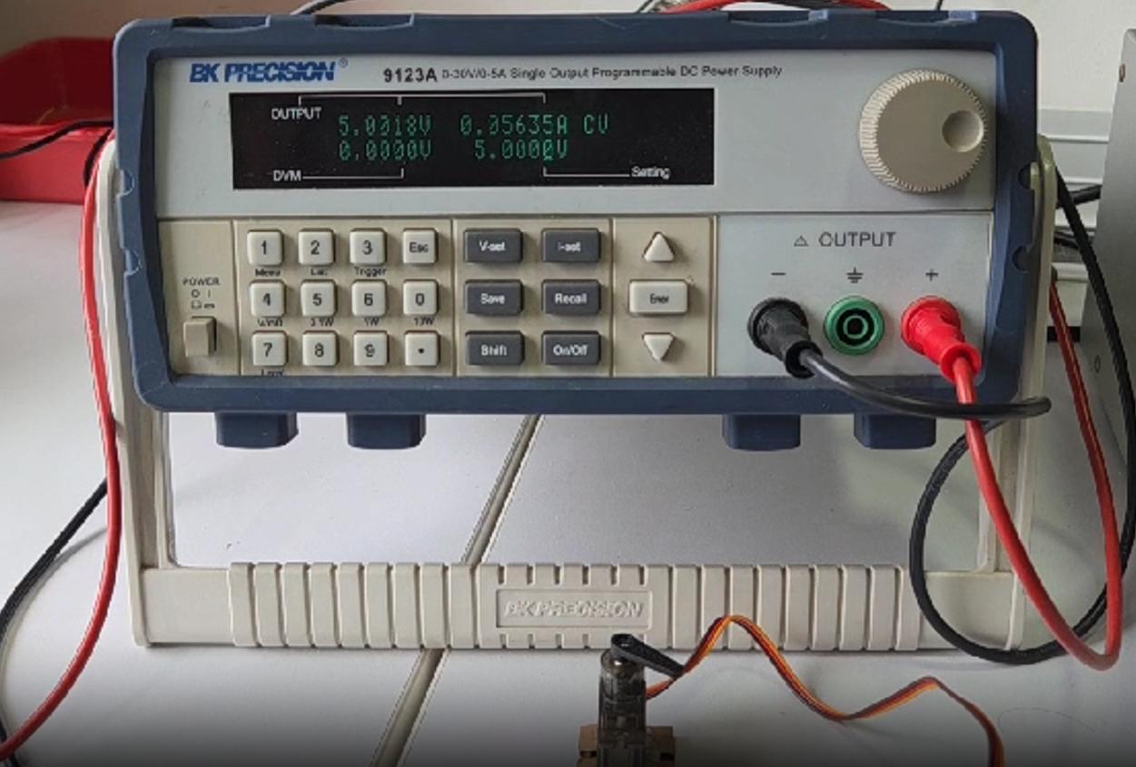
This week we measured a output device's current aand power using the bench power supply. We used Noel's Servo attached PCB to measure it's power and current consumption.
Group AssignmentThe below image shows the current consumption of the servo in action. 5V is provided to the servo, and it's consuming approximately 0.05 A current. Abd under load we found that the servo consumes a maximum of 0.3 A. We can calculate the Power consumption of the device using the formula P = V x I. The maximum power consumption of the servo under load is 1.5W according to our observation.
Learning Section
WS2812B Individually Addressable LEDs
The WS2812B is a smart RGB LED that can be individually controlled, allowing for complex lighting effects and animations. It operates at 5V and uses a single data line for control, making it easy to integrate into various projects.
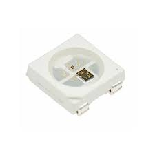
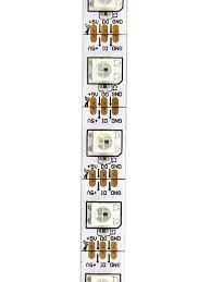
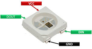
Photo credit: 1. Amazon.in 2. Zbotic 3. sainisagar7294: Instructables
There are mainly three lines of wire for controlling the WS2812B LED Arrays: VCC, Data, GND
The above given photo shows the single WS2812B LED pixel with fours pins: VCC, DIN, DOUT and GND. The middle photo shows how a series of LEDs are connected to form a Addressable LED Strip.
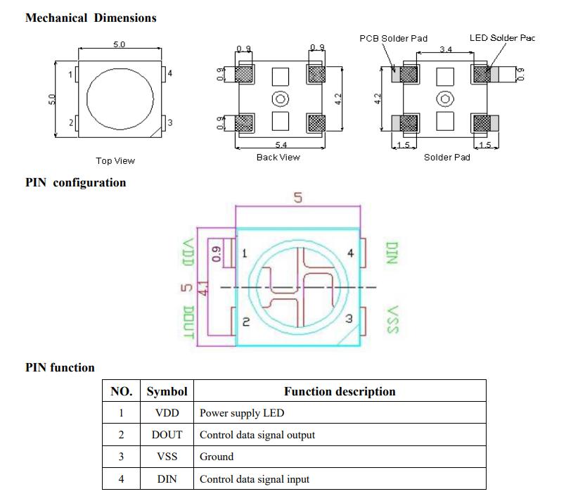
Photo credit: Adafruit WS2812B Datasheet
The pin functions are explained briefly in the above given image. The logic of the WS2812B LEDs is that each pixel has an Individual Integrated Chip controlling three different LEDs in a single Pixel (Red, Green, Blue). Therefore every pixel can be controlled indiviually as every pixel has an individual IC controlling its respective 3 LEDs, making it possible to control the color of each LED in each pixel in a array of pixels of a LED strip. The Data line passes through every individual pixel, in the program we need to mention the number of LEDs connected so that we can control each LED in the array. Thus, these LED strips are also called Individually Addressable LED Strips as the LEDS can be addressed individually. This makes it possible to create beautiful animations, displays and so on.
WS2812B DocumentationWS2812B LEDs are controlled using a single data line, which makes them easy to integrate into projects. The data is sent in a specific timing sequence, allowing for precise control of each LED's color and brightness.
The WS2812B uses 5V but my MCU uses 3.3 V logic level, therefore I needed the 5V output. So I had to make a logic level shifter. So I learned more about Logic Level Shifter.
I refered to this documentation Logic Level Shifters
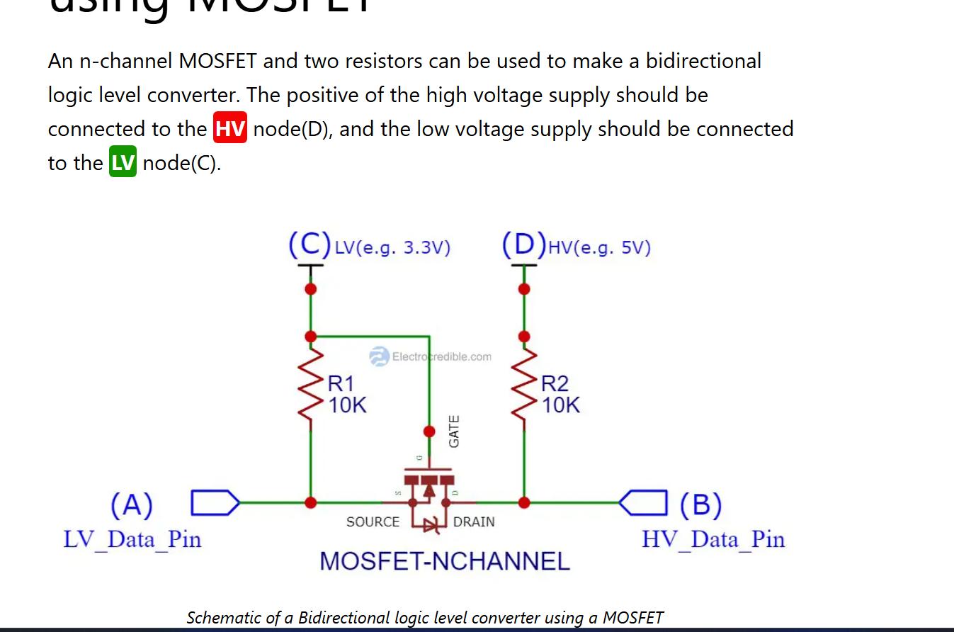
Photo credit: electrocredible
I used Falstad to visualise and simulate the electronic circuit for Logic Level Shifters. The below image shows the logic level shifter circuit.
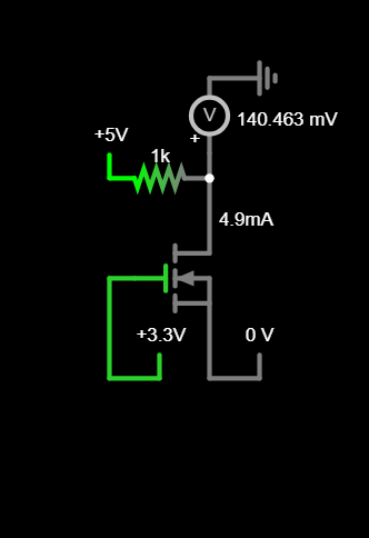
The below video shows how the logic shifting works in the circuit.
I have included the logic level shifter in the circuit scheamtic. You can follow my input week's assignment for the complete schematic.
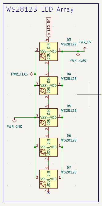
WS2812B Array
The WS2812B LEDs are connected in a series. The Data Signal line is connected to the first LED's DATA IN (DIN) pin. The Data OUT(DOUT) of the first LED is connected to Data IN(DIN) of the next LED. This continues throught the Series.
Programming WS2812B LEDs using the Adafruit Neopixel library requires certain declarartions in the beginning. To understand the declaration I reffered to the documentation given below. I have mentioned the parameters below the link.
Adafruit Neopixel Constructor & Destructor DocumentationParameters
Adafruit_NeoPixel pixels(NUMPIXELS, PIN, NEO_GRB + NEO_KHZ800)n - Number of NeoPixels in strand.
p - Arduino pin number which will drive the NeoPixel data in.
t - Pixel type - add together NEO_* constants defined in Adafruit_NeoPixel.h, for example NEO_GRB+NEO_KHZ800 for NeoPixels expecting an 800 KHz (vs 400 KHz) data stream with color bytes expressed in green, red, blue order per pixel.
TouchNav SAMD21 Board
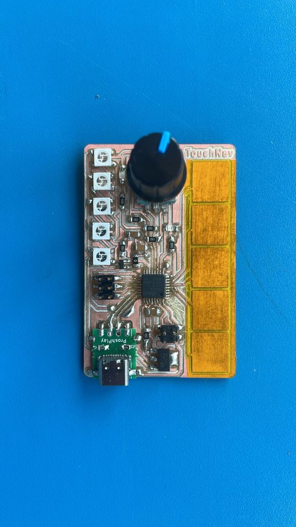
I used my input week's assignment for testing the WS2812B LEDs. The TouchNav Board that I designed consisted of 5 WS2812B Leds in series connected to the GPIO pin 11. I test the WS2812B LEDS using the example code provided by Adafruit.
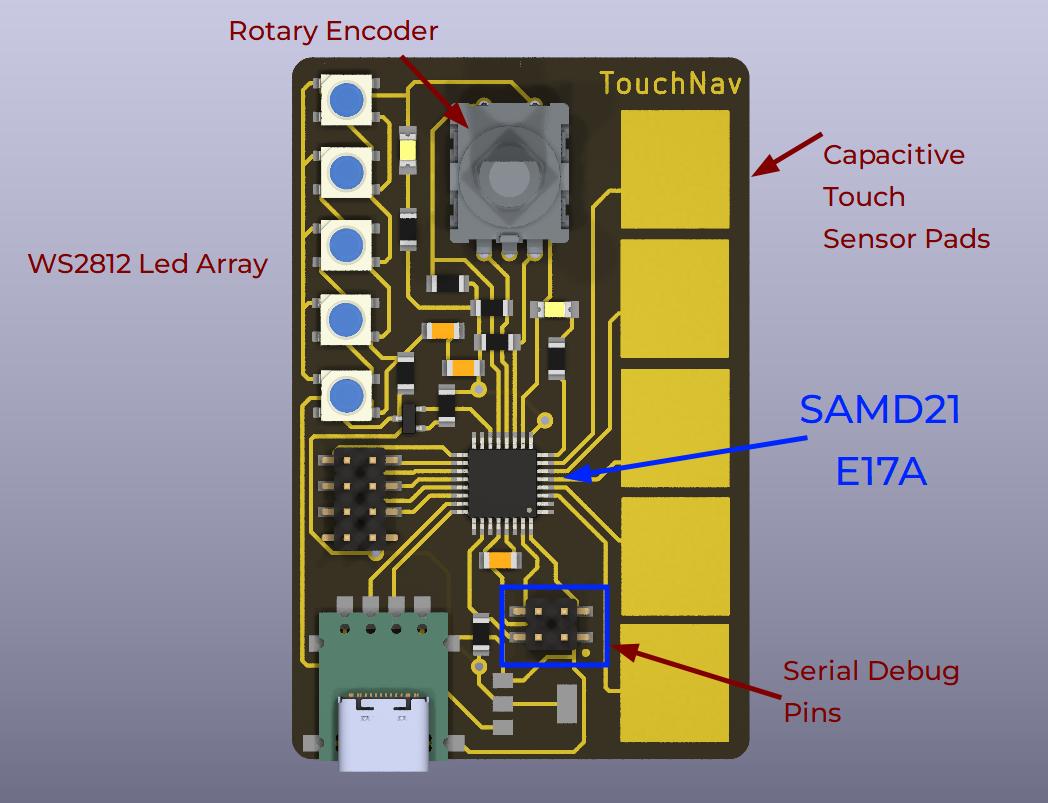
THe above image shows the layout the WS2812B LEDs along with the input devices on the board.
#include


// Pin number of WS2812B
#define PIN        11 //

// Number of WS2812B LEDs
#define NUMPIXELS 5

// When setting up the NeoPixel library, we tell it how many pixels,
// and which pin to use to send signals.
Adafruit_NeoPixel pixels(NUMPIXELS, PIN, NEO_GRB + NEO_KHZ800);

#define DELAYVAL 500 // Time (in milliseconds) to pause between pixels

void setup() {


	pixels.begin(); // INITIALIZE NeoPixel strip object (REQUIRED)
}

void loop() {
	pixels.clear(); // Set all pixel colors to 'off'

	// The first NeoPixel in a strand is #0, second is 1, all the way up
	// to the count of pixels minus one.
	for(int i=0; i < NUMPIXELS; i++) {
	pixels.setPixelColor(i, pixels.Color(0, 150, 0));

	pixels.show();
	delay(DELAYVAL);
	}
}
After successfully testing the WS2812B leds, I added that to the board functionalities to show volume increase and decrease using the rotary encoder. You can refer to my previous week's documentation for detailed information on the board and it's features.
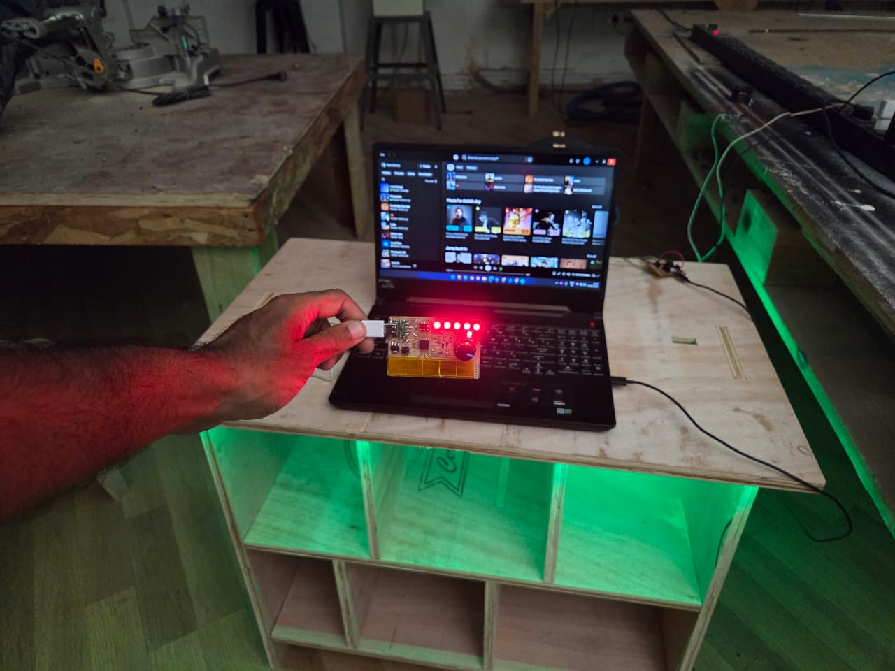
Spotify PlayerI programmed the TouchNav Board to act as a Spotify Controller using the HID Library. It allows me to use the touch pads to control playback like Play/Pause, Next, Previous, and Seek Forward/Backward. The Rotaryencoder allows me to control the volume of the device and the increase and decrease in Volume is indicated using the WS2812B LEDs. You can watch the below video to see how it works, the detailed documentation is in Input Week assignemnt.
Audio Amplifier Circuit
After testing the WS2812B LEDs, as part of final project I wanted to make a speaker system to play music from Spotify. As I wanted to make this system, this week was the best time to design a PCB Board with Speakers as output. That's why I decided to make an Audio Amplifier Circuit for driving speakers.
XIAO ESP32S3
I used the XIAO ESP32 S3 Board for this week's assignment for wifi compatibility. I wanted to test the Spotify communication part along with the audio streaming. The chose this board because it has wifi but I didin't realise that the board doesn't have an Analog Output. Below the pinout of the XIAO ESP32 S3.
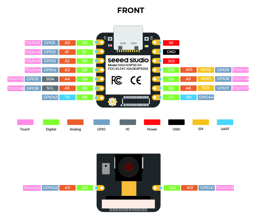
Photo credit: Seeed Studio
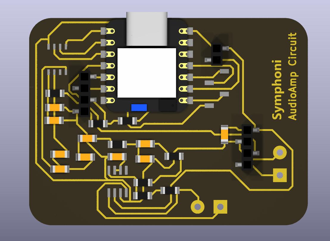
The below image is of the 3D Model of the Audio Amplifier Board I designed as part of this week.
The Xiao ESP32 S3 doesn't have an analog output to drive an analog speaker driver. I needed to play music and songs as part of my final project. So to get analog output, I needed to use an digital to analog converter (DAC). The XIAO ESP32 S3 has I2S pins which can give digital audio output. So we need a I2S DAC and an Audio Amplifier to drive the speakers. I am using a PT8211 I2S DAC and LM4861 Amplifier
I2S - Inter-Integrated Circuit Sound
I2S is a synchronous, serial communication protocol for exchanging digital audio data between sound-processing devices such as microcontrollers, audio codecs, or digital signal processors. It uses a shared clock signal to synchronize the data transmission between devices and transmits audio in a serial fashion. The protocol is often used in designs that require high-quality audio transmission.
I refered to thisDigikey webpage to understand I2S
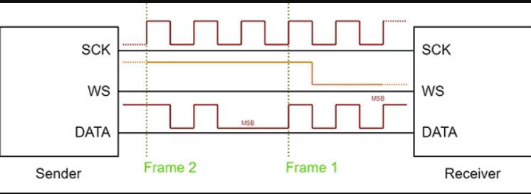
Photo credit: Digikey
This image shows an example data transmission of two frames consisting of three bits each. The data gets clocked out on the rising edge of SCK. Finally, note how the WS transition happens one clock cycle before frame 2 begins.
PT8211 I2S DAC
PT8211 is a dual channel, 16 bit Digital-to-Analog Converter IC utilizing CMOS technology specially designed for the digital audio applications. The internal conversion architecture is based on a R-2R resister ladder network, internal circuit is well matched and a 16 bit dynamic range is achieved even in whole supply voltage range. PT8211 also enhanced the performance of timing responsibility in digital serial bus, in a company with the fast switching R-2R network that make 8X oversampling audio signal is also supported.
I referred to this documentation for understanding the PT8211 and I have used the contetn and images for my documentation from the same.
PT8211 DocumentationPT8211 can be supported wide range of sample frequency; it is compatible with TDA1311 by functionally. Its digital input timing format is Least Significant Bit Justified (LSBJ), or so called Japanese input format. Digital code format is two's complement and MSB first. PT8211 is available in 8-pin SOP or DIP.
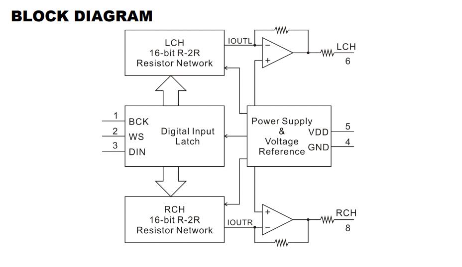
Photo credit: Princeton Technology Corp
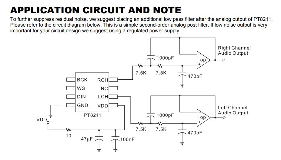
Photo credit: Princeton Technology Corp
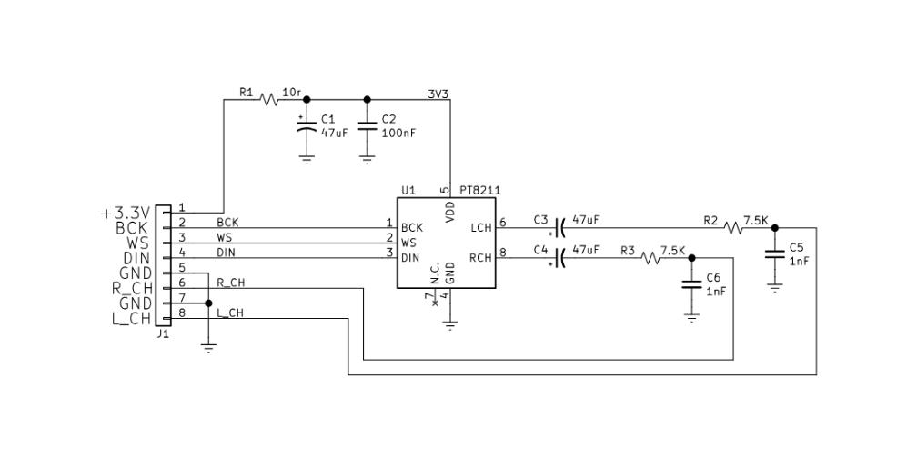
Photo credit: Princeton Technology Corp
The serial bus input data format of PT8211 is Japanese or called LSBJ (Least Significant Bit Justified) format. Each valid DIN data will be shifted to the input register in the rising edge of the BCK, only the first 16bit data ( from MSB) is valid if the input data length is more than 16bits, other data bit will be truncated. The clock frequency of the BCK could run up to 20MHz and supported to 8x over-sampling in 48KHz WS clock rate. Both left and right data words are time multiplexed.
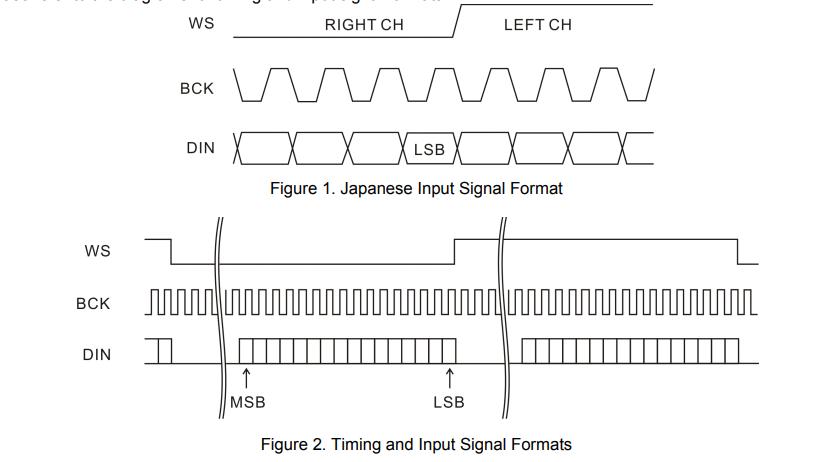
Photo credit: Princeton Technology Corp
I refered to a youtube video and the PT8211 Documentation to design the schematic for my circuit. The video showed a reference circuit connection, which I applied to my circuit design.
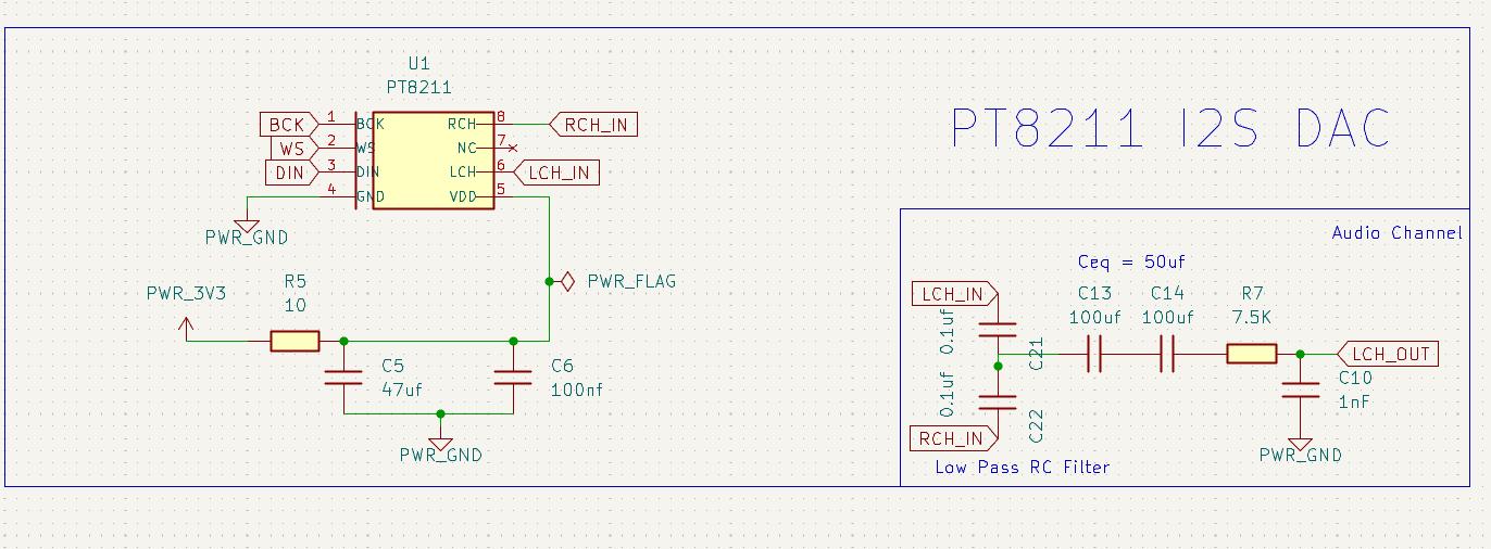
This below image shows the section of the Schematic which has the PT8211 I2S DAC and shows the output of the DAC through an Low Pass RC Filter. The I2S DAC outputs 2 Channel: Left and Right. I will be using only one output speaker therefore, the left and right channel outputs and connected together through a Low PAss RC Filter to give out a single Output which will go to the amplifier.
LM4861 Amplifier
The LM4861 is a bridge-connected audio power amplifier capable of delivering 1.1W of continuous average power to an 8Ω load with 1% THD+N using a 5V power supply.
LM4861 Amplifier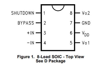
Photo credit: Digikey
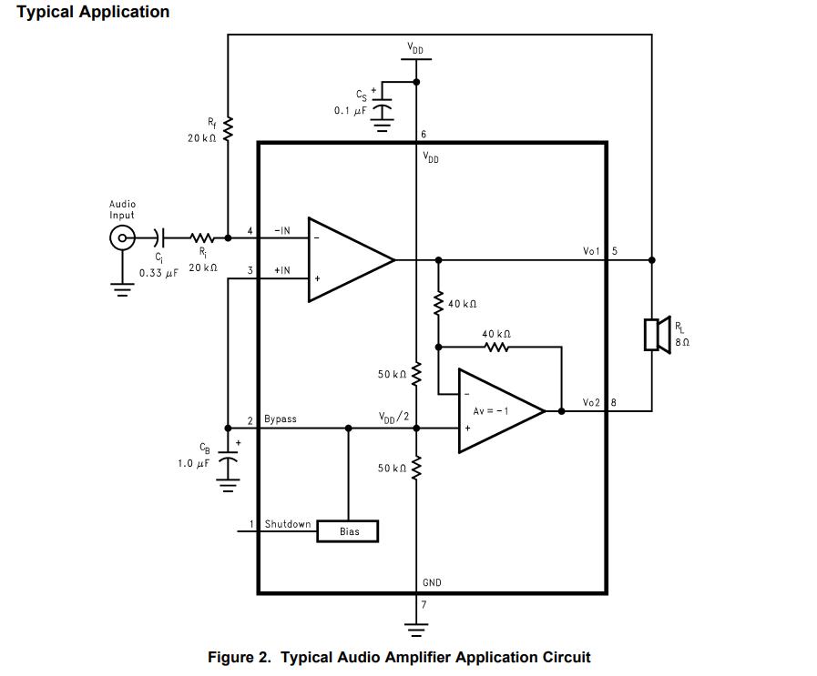
Photo credit: Digikey
The output from XIAO ESP32S3 is digital I2S Signals through the pins WS(Word Select), BCLK(Bit Clock) and DIN(Data Pin).
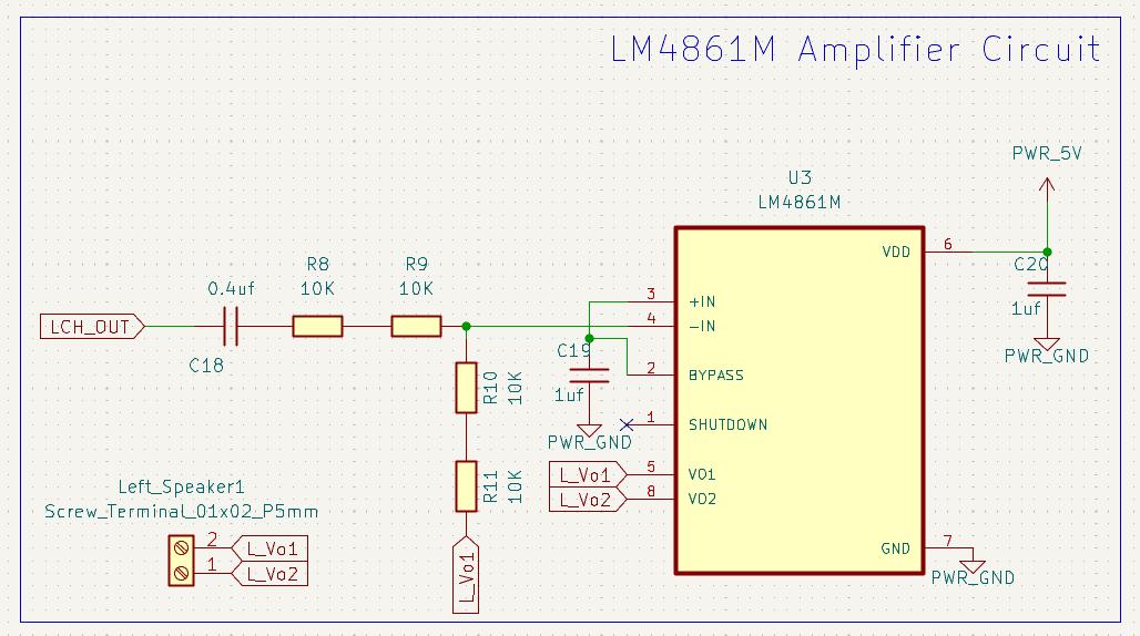
The below image shows the schematic portion of the LM4861 Amplifier Connection. The Output from the I2S DAC is input to the Amplifier and then the amplifier outputs to the speaker.
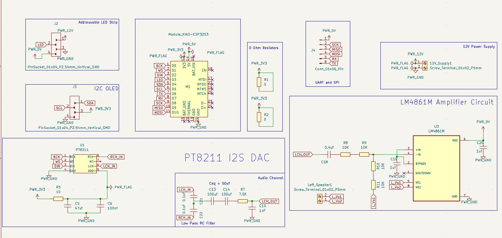
The final schematic is given below for the Audio Amplifier Circuit Board.
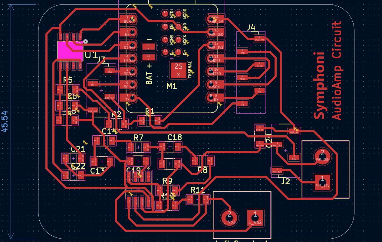
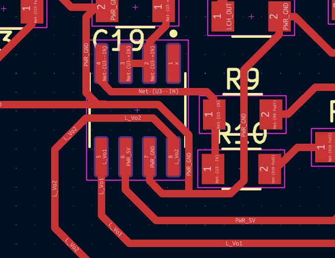
PCB Design
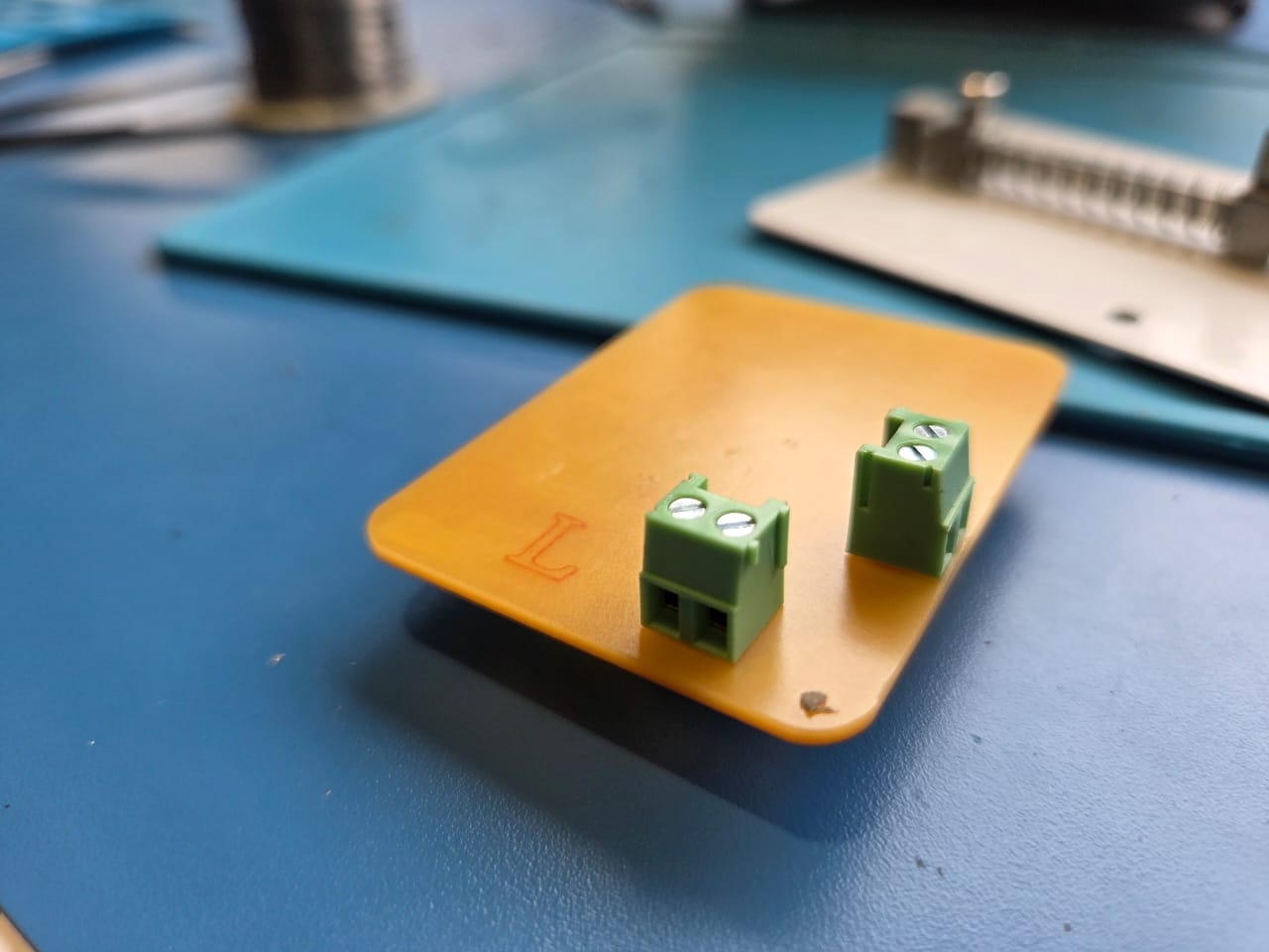
The PCB Design was done in KiCad. You can see two screw terminals, one is for the 12V input and the other is for the output to the speaker.
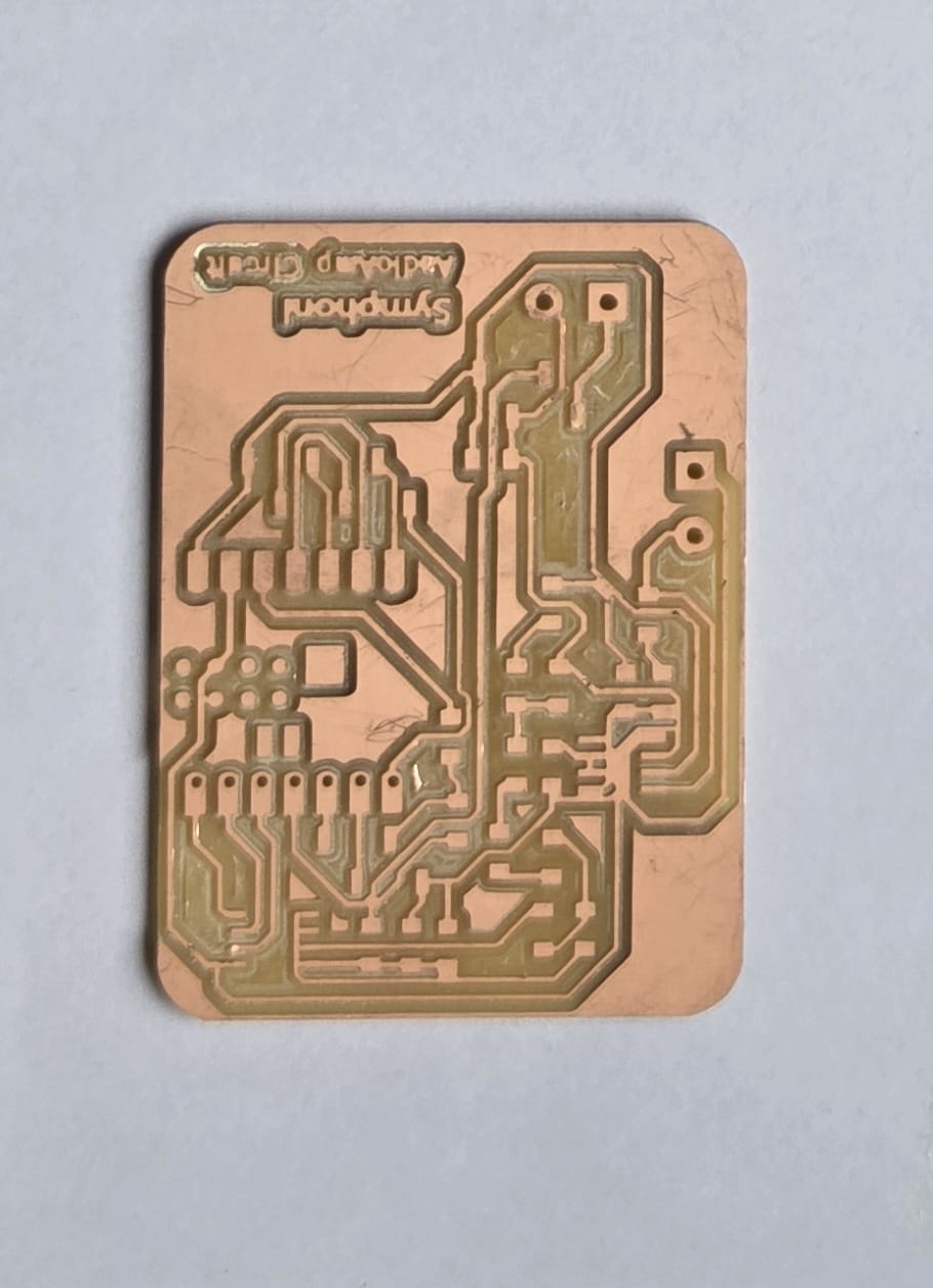
PCB Milling and Assembly
The below image shows the closeup of the PCB after milling. After soldering I realised that the traces were not cut properly, therefore there were many shorted.
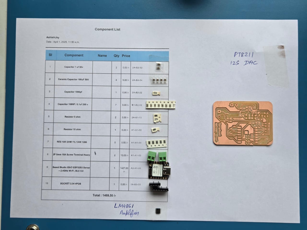
Below are the components before soldering.
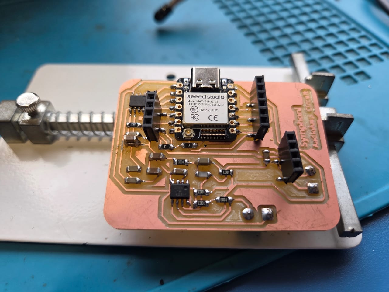
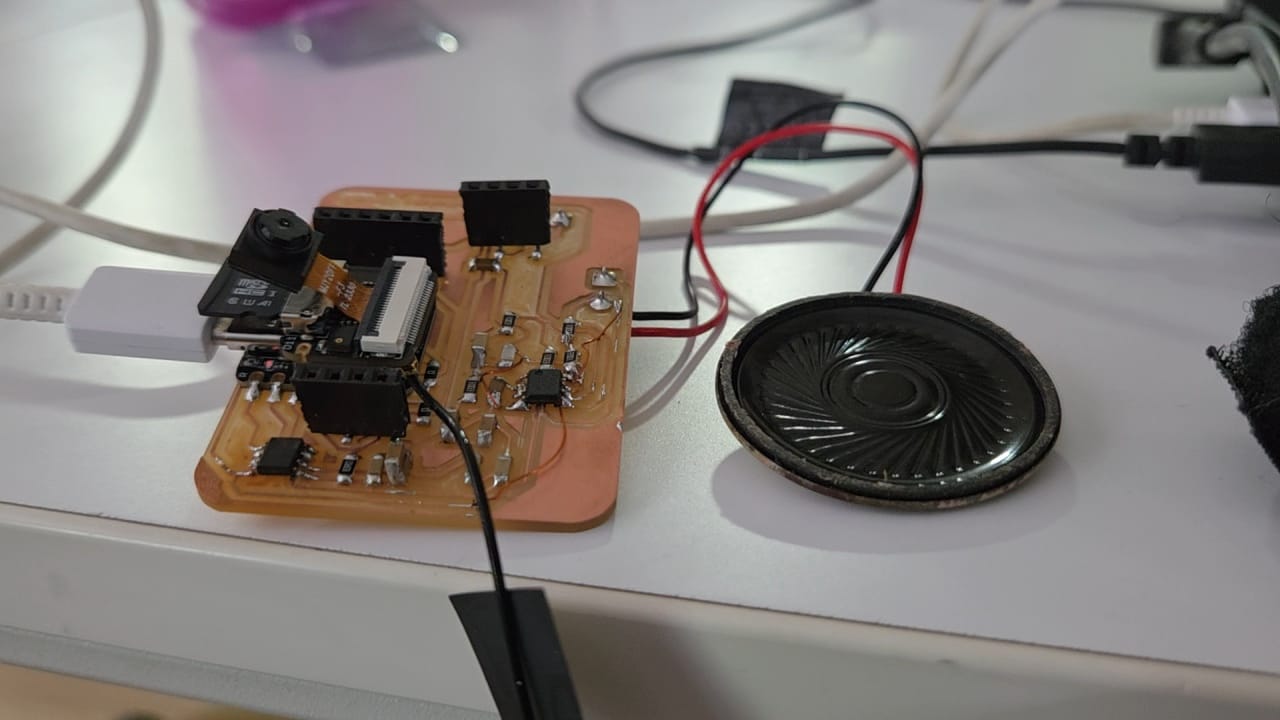
The assembled board looks like this
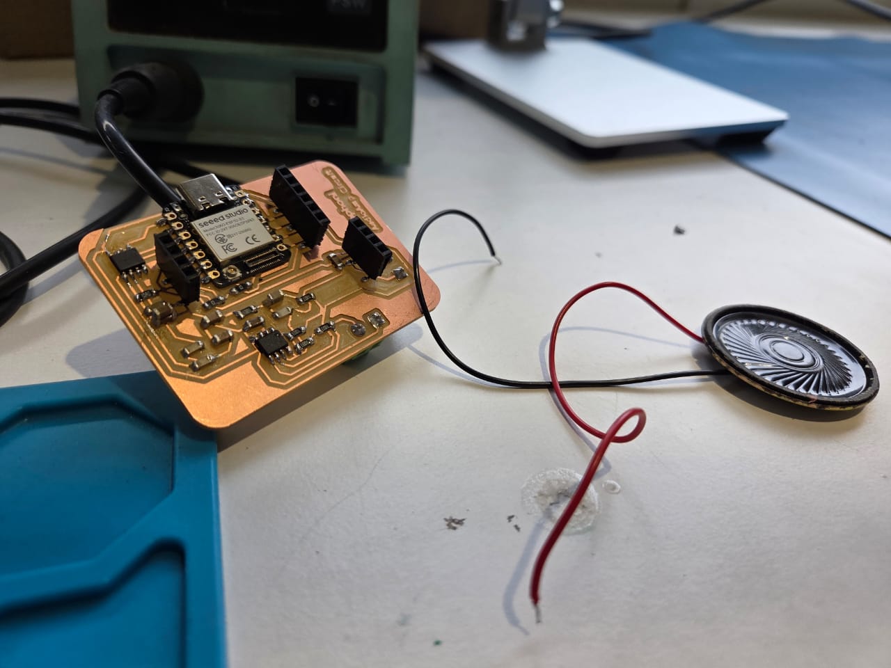
Initially I tested with this speaker available at the lab.
Testing the current and Power of my Board
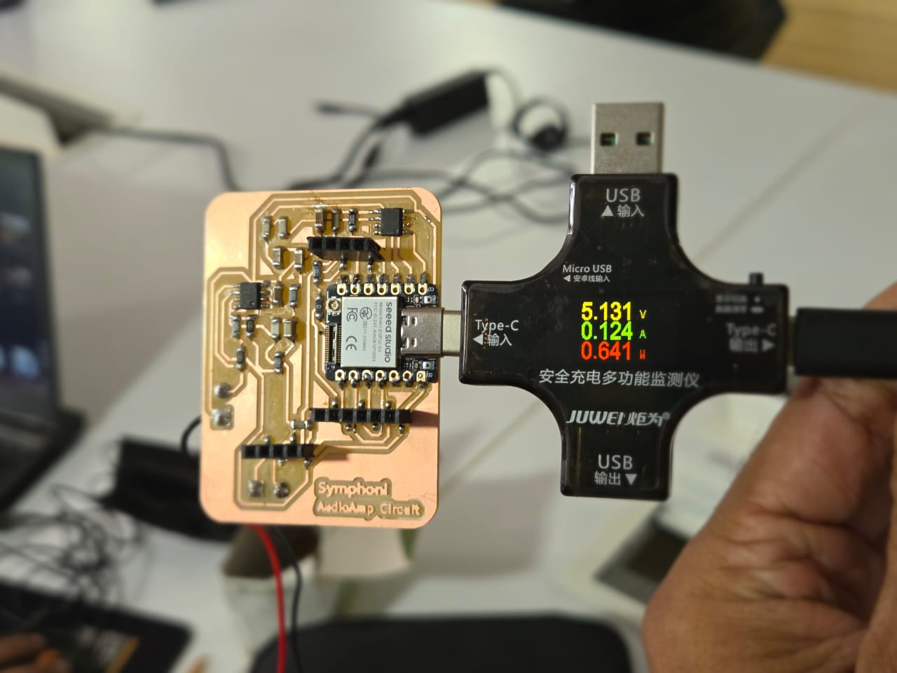
You can clearly see the errors in PCB where the traces are shorted. I have made boxes around the shorted traces.
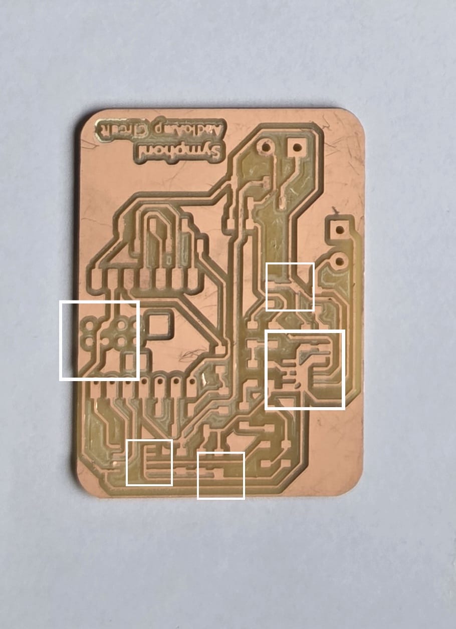
I had to cut down the shorted traces because I had already soldered all the components and there was no time to mill a new board. That's why I had perform a major surgery on my board by using insulated wires and soldering it to connect it
Programming
The I2S pins for my board are:
- BCK - D0
- WS - D1
- DIN - D2
Internet Radio using ESP32
To test the speaker functionality, I uploaded a example code from a youtube video from DroneBotWorkshop showing esp32 I2S capabilities. Please maske sure you connected the exernal antenna provided with the Board for Wifi functionality.
The below link is for the documentation provided fro the video
ESP32 - I2S ProtocolI tested the setup with the code. The speaker was not functioning properly, as the output was very noisey and unclear.
The Audio.h library must be installed for this. The library can be downloaded from the below link.
ESP32 AudioI2S Github Repo
// Include required libraries
#include "Arduino.h"
#include "WiFi.h"
#include "Audio.h"
// Define I2S connections
#define I2S_DOUT 14
#define I2S_BCLK 27
#define I2S_LRC 12
// Create audio object
Audio audio;
// Wifi Credentials
String ssid ="Fab_Lab";
String password ="Qwerty~!@";
void setup() {
// Start Serial Monitor
Serial.begin(115200);
// Setup WiFi in Station mode
WiFi.disconnect();
WiFi.mode(WIFI_STA);
WiFi.begin(ssid.c_str(), password.c_str());
while (WiFi.status() != WL_CONNECTED) {
delay(500);
Serial.print(".");
}
// WiFi Connected, print IP to serial monitor
Serial.println("");
Serial.println("WiFi connected");
Serial.println("IP address: ");
Serial.println(WiFi.localIP());
Serial.println("");
// Connect MAX98357 I2S Amplifier Module
audio.setPinout(I2S_BCLK, I2S_LRC, I2S_DOUT);
// Set thevolume (0-100)
audio.setVolume(10);
// Connect to an Internet radio station (select one as desired)
audio.connecttohost("http://vis.media-ice.musicradio.com/CapitalMP3");
//audio.connecttohost("mediaserv30.live-nect MAX98357 I2S Amplifier Module)
// audio.connecttohost("http://mp3.ffh.de/radioffh/hqlivestream.mp3");
// audio.connecttohost("stream.1a-webradio.de/deutsch/mp3-128/vtuner-1a");
// audio.connecttohost("http://0n-70s.radionetz.de:8000/0n-70s.mp3");
// audio.connecttohost("0n-80s.radionetz.de:8000/0n-70s.mp3");
}
void loop()
{
// Run audio player
audio.loop();
}
// Audio status functions
void audio_info(const char *info) {
Serial.print("info "); Serial.println(info);
}
void audio_id3data(const char *info) { //id3 metadata
Serial.print("id3data "); Serial.println(info);
}
void audio_eof_mp3(const char *info) { //end of file
Serial.print("eof_mp3 "); Serial.println(info);
}
void audio_showstation(const char *info) {
Serial.print("station "); Serial.println(info);
}
void audio_showstreaminfo(const char *info) {
Serial.print("streaminfo "); Serial.println(info);
}
void audio_showstreamtitle(const char *info) {
Serial.print("streamtitle "); Serial.println(info);
}
void audio_bitrate(const char *info) {
Serial.print("bitrate "); Serial.println(info);
}
void audio_commercial(const char *info) { //duration in sec
Serial.print("commercial "); Serial.println(info);
}
void audio_icyurl(const char *info) { //homepage
Serial.print("icyurl "); Serial.println(info);
}
void audio_lasthost(const char *info) { //stream URL played
Serial.print("lasthost "); Serial.println(info);
}
void audio_eof_speech(const char *info) {
Serial.print("eof_speech "); Serial.println(info);
}
1 KHz Test Wav from SD Card
The initial radio test was to just test the speaker output without adding any external peripherals. After testing the interenet Radio, I wanted to try reading from an SD Card and playing that back for that I tried two basic tones: 1KHz and 10KHz.
To read an SD card we usually need a SD Card Reader module but as I was using the XIAO ESP32 S3 Board it comes with a attachement of a Camera and a SD Card reader which can be attached easily to the back of the board.
File System and XIAO ESP32S3 SenseYOu can refer to the above link to get started with XIAO ESP32 S3 and SD Card File System. You have follow the documentation to setup the SD Card and the load the files in the SD CArd and test it's functionalities.
I followed the PT8211 I2S DAC Test with ESP32 youtube video to test the speaker output from the SD Card. The code below is taken from the github repo that I am linking below.
PT8211_Breakout Github Repo by GadgetRebootThis is a simple code to test the audio output from the SD Card through the I2S DAC and Amplifier. IT uses the Audio library from schreibfaul1 and the SD library. I just modified the pin data according to my board. You can get the audio data from Audio Tones.
/*
  ESP32 I2S MP3/WAV SD Card Playback Test

  Hardware:  Uses external I2S DAC or ESP32 built in DAC

  Uses ESP32-audioI2S Library https://github.com/schreibfaul1/ESP32-audioI2S

  Gadget Reboot
*/

#include "Arduino.h"
#include "Audio.h"
#include "SD.h"
#include "FS.h"

// SD Card SPI pins
#define CS             21
#define SPI_MOSI      9
#define SPI_MISO      8
#define SPI_SCK       7

// I2S external DAC pins
#define I2S_DOUT      3   // data in to I2S module
#define I2S_LRC       2   // WS (word select)
#define I2S_BCLK      1   // bit clock


// uncomment one of these to set up audio interface for internal/external DAC
Audio audio;  // use external I2S DAC
//Audio audio(true, I2S_DAC_CHANNEL_BOTH_EN);  // use esp32 internal DAC

void setup() {
  Serial.begin(115200);

  // configure SPI for SD card access
  pinMode(CS, OUTPUT);
  digitalWrite(CS, HIGH);
  SPI.begin(SPI_SCK, SPI_MISO, SPI_MOSI);

  // init SD card
  if (!SD.begin(CS)) {
    Serial.println("SD card error");
    while (true);
  }

  // configure external I2S DAC - comment out these lines if using internal DAC
  audio.setPinout(I2S_BCLK, I2S_LRC, I2S_DOUT);
  audio.setI2SCommFMT_LSB(true); // data format for PT8211 is different from some other DACs. Comment out if using other formats

  audio.setVolume(50);

  // play specific mp3 or wav file on SD card
  audio.connecttoFS(SD,"/1khz.wav");
  //audio.connecttoFS(SD, "/10khz.wav");
}

void loop() {
  audio.loop();
}
10KHz Test Wav from SD Card
The 10KHz test is done below.
8 Bit music test
After testing the 1khz and 10Khz, I wanted to test some music. So I loaded a 8bit music that I got from online and tried playing it. The sound was decent quality but not very clear. It still had noise. I tested it with two speakers one was small and the other was bigger.
Below is the music test with the smaller speaker
Below is the music test with the bigger speaker.
All the tests proved that the audio was decent with noise. The output was noisey, maybe something wrong with filter circuit or amplifier.
Power Delivery (PD)
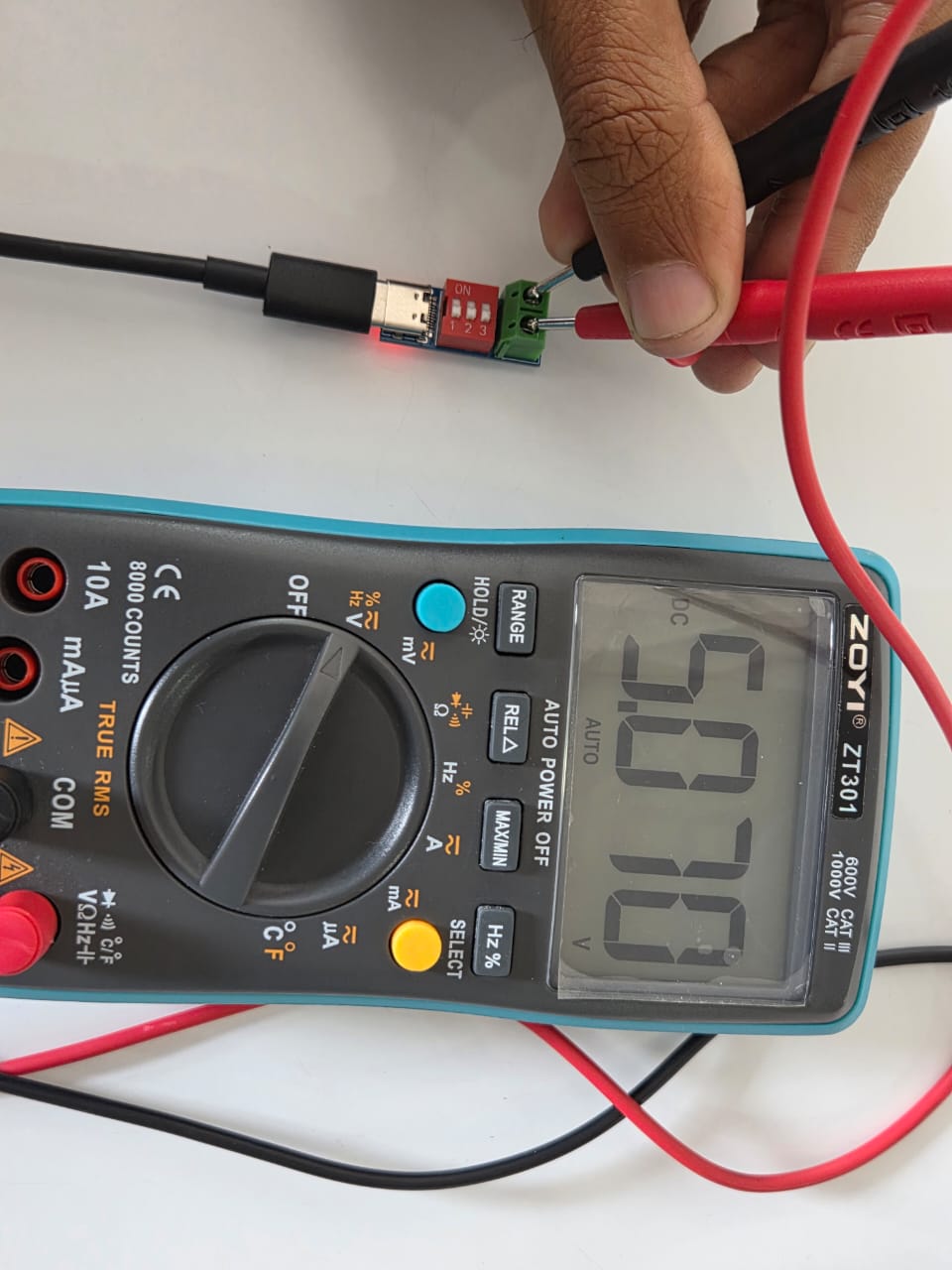
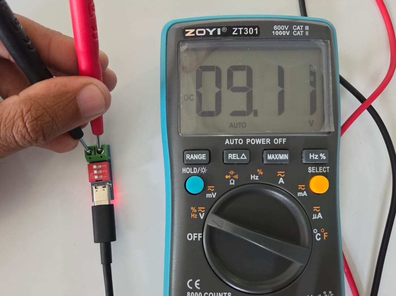
USB Power Delivery is a common fast-charging standard that can be implemented in all USB-powered gadgets.
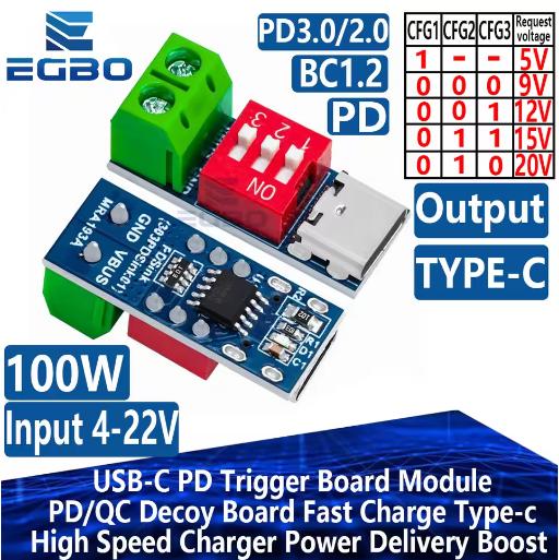
USB Power Delivery is much more powerful, supporting up to 240W of power to charge up even the most demanding gadgets such as laptops. It's also safer, as gadgets and chargers communicate with each other over the USB cable to confirm the optimal charging power level. This handshaking approach supports voltage steps at 5V, 9V, 15V, 20V, and beyond for power outputs ranging from 0.5W to 240W.
USB-C PD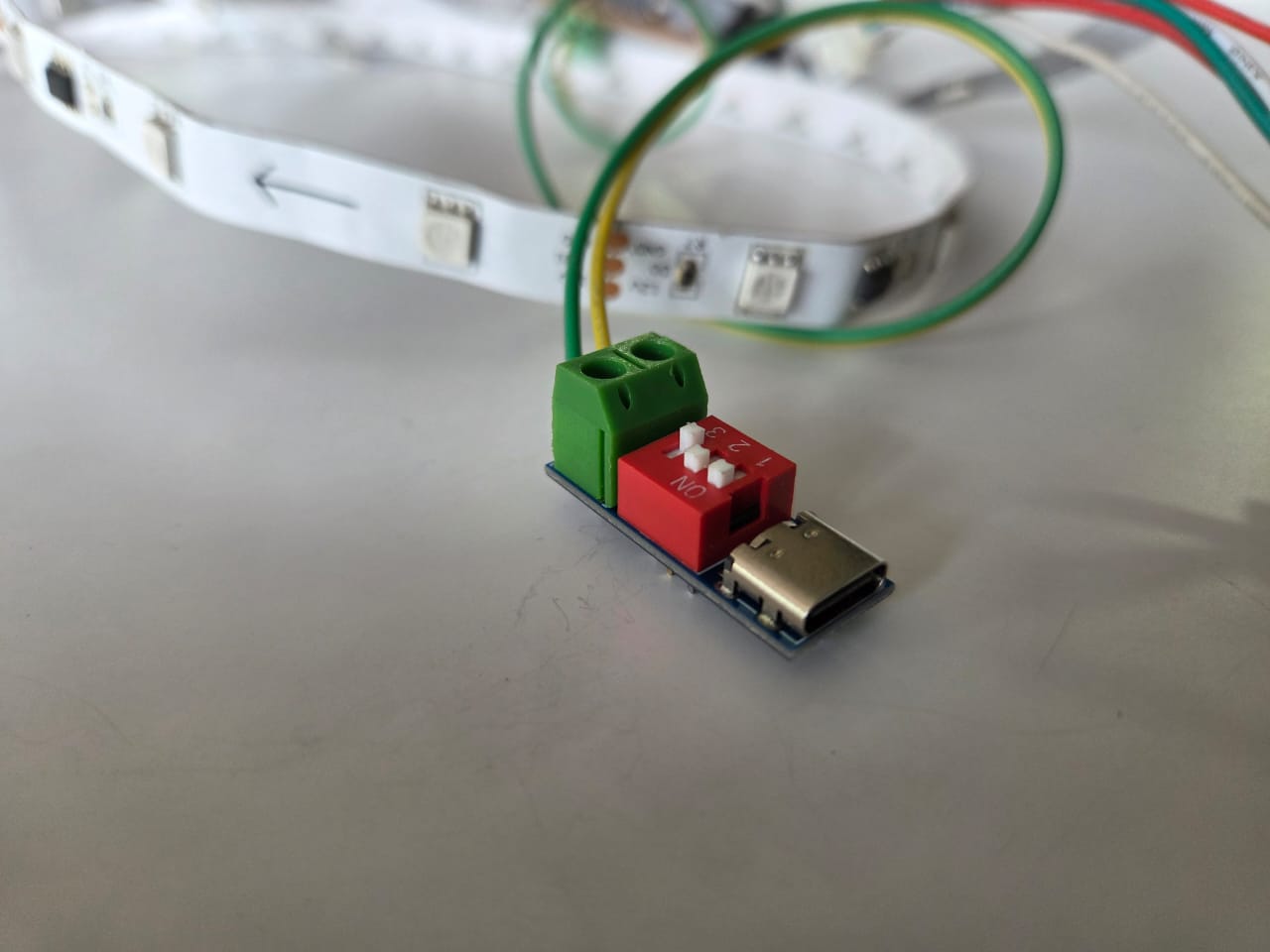
WS2811 LED Strip.
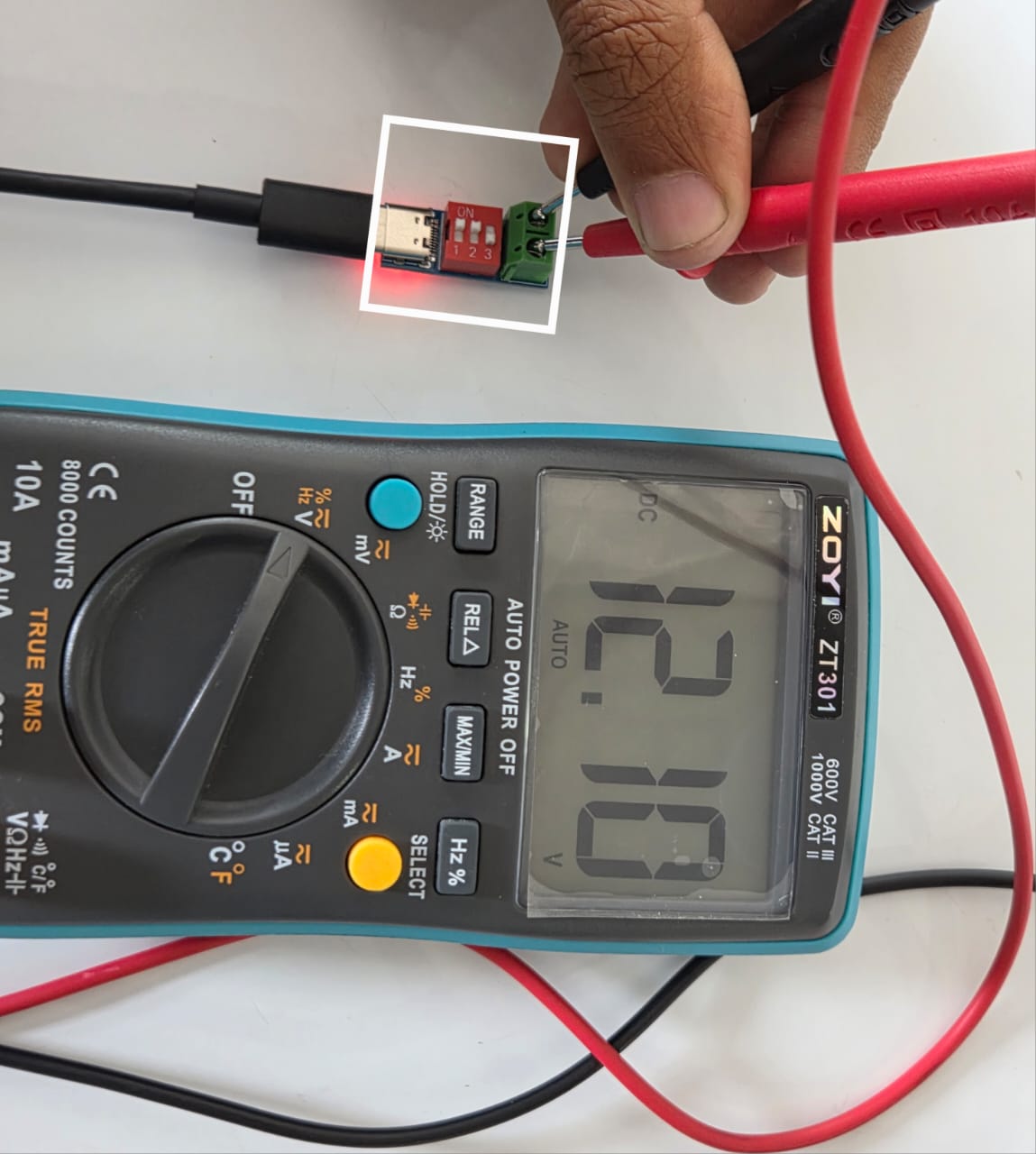
WS2811 LED Strip has a similar working principle as the WS2812B LEDs, but the major difference that is relevant to us is that the WS2811 LEDs work on 12V and the Data In should be 3.3V or 5V. The LED Strip that I have is a variant wherein the three Pixels are controlled by one single WS2811 IC. You can refer to the below documentation on interfcaing WS2811 RGB Led Strip with Arduino to know more about them.
Interfacing WS2811 Led Strip with ArduinoI needed 12V Output for my WS2811 Addressable LED Strip. That's why I used a Power Delivery module to power my 12V LED Strip
WS2811 LED Strip with Board
I used the example from Adafruit 'strandtest.ino'. I tested the 12V Addressable LEDs using the test code
I attached the LED Strip to the Media Cabinet that I made during the Computer Controlled Machining . This is where Symphoni - The Turntable will be placed. I wanted to use the board I designed last week and communicate with this week's board - Speaker
Hero Shots
TouchNav SAMD21 Board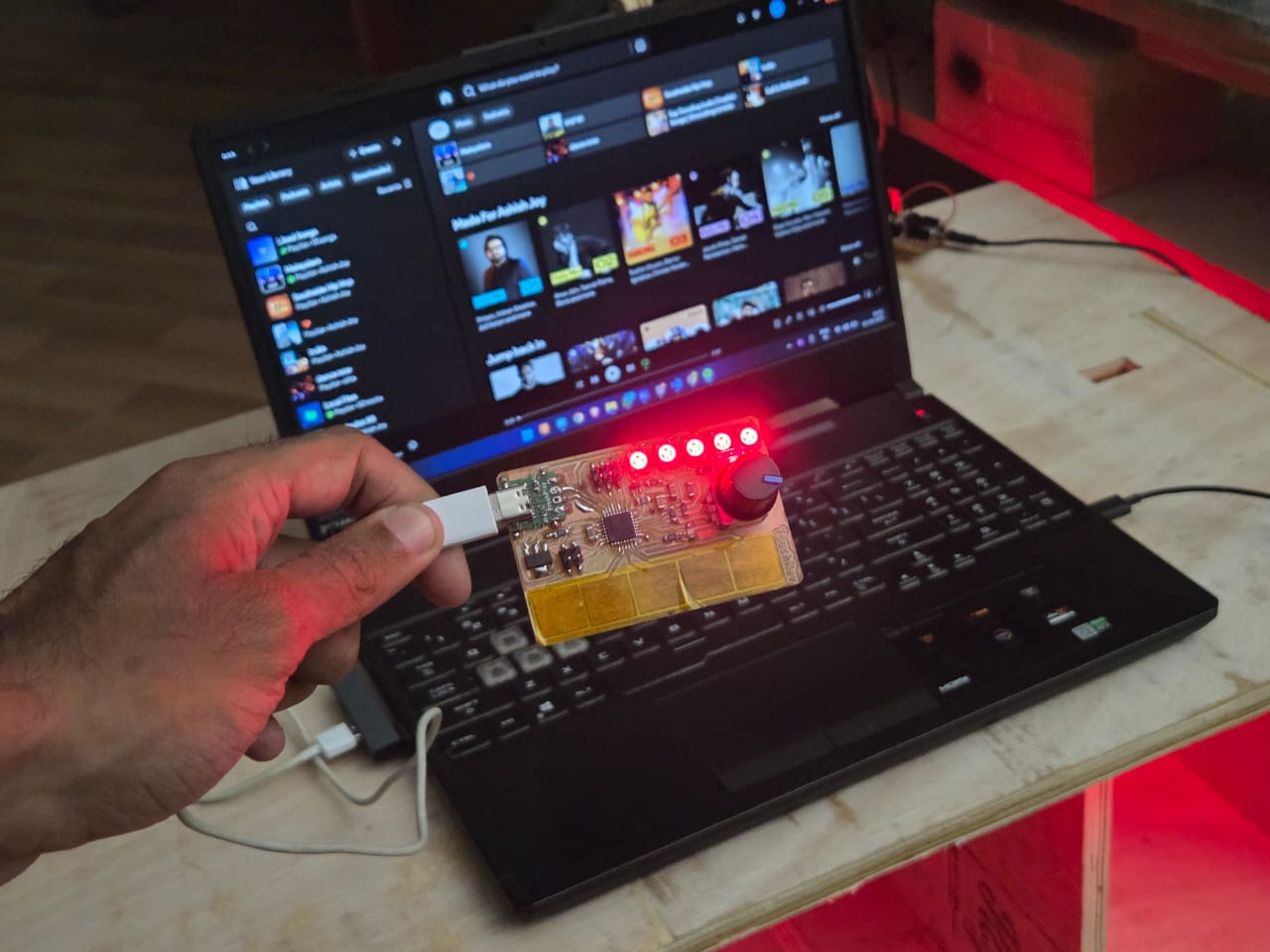
Design Files
You can download my design files from below
TouchNav SAMD21 Board
- KiCad Files
AudioAmp Circuit XIAO ESP32s3
- KiCad Files