Week 17
Applications and Implications
What will it do?
My project is a indore delivery robot that can be used to deliver food or drinks or any other item to a user in an office environment from point A to point B.It will have a driving system that consist of 4 driving wheels and two driven wheel that will be used to move the robot.It will have two matrix display that can be used to display some simple emotions or status of robot.And it also will have a time of flight sensor to detect objects in front of the robot.
Who's done what beforehand?
There are many projects that are similar to my project but they are not exactly the same as my project. There are many projects that are used to deliver food or drinks in a restaurant or a hotel. But my project is a simple robot that can be used in an office environment to deliver food or drinks or any other item.Pudu robotics is a company that makes a robot that can be used to deliver food or drinks in a restaurant or a hotel.The company makes beautiful and modern and practical robots.
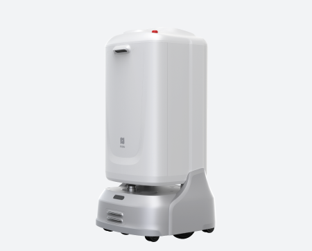
Image Source: Pudu Robotics
The other projects used for inspiration was an an outdoor robot starship deliveries It was looking too good and aesthetic and i felt it was more practical than most of the other projects.
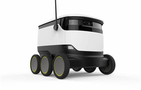
Image Source: starship deliveries
What sources will you use?
The sources that will be used for my project are the local market for the materials, Online market and the Fab Lab for the 3D printing and laser cutting and PCB milling. The electronics will be made using the inventory of the Fab Lab.
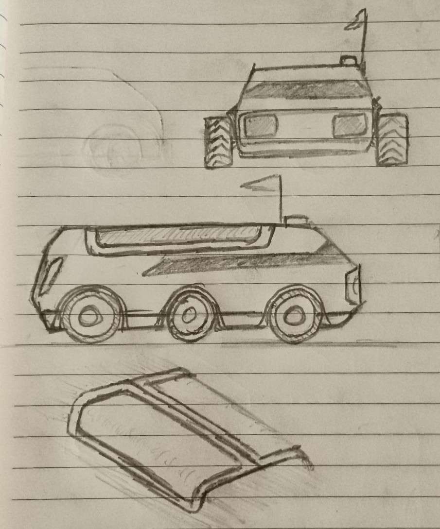
What will you design?
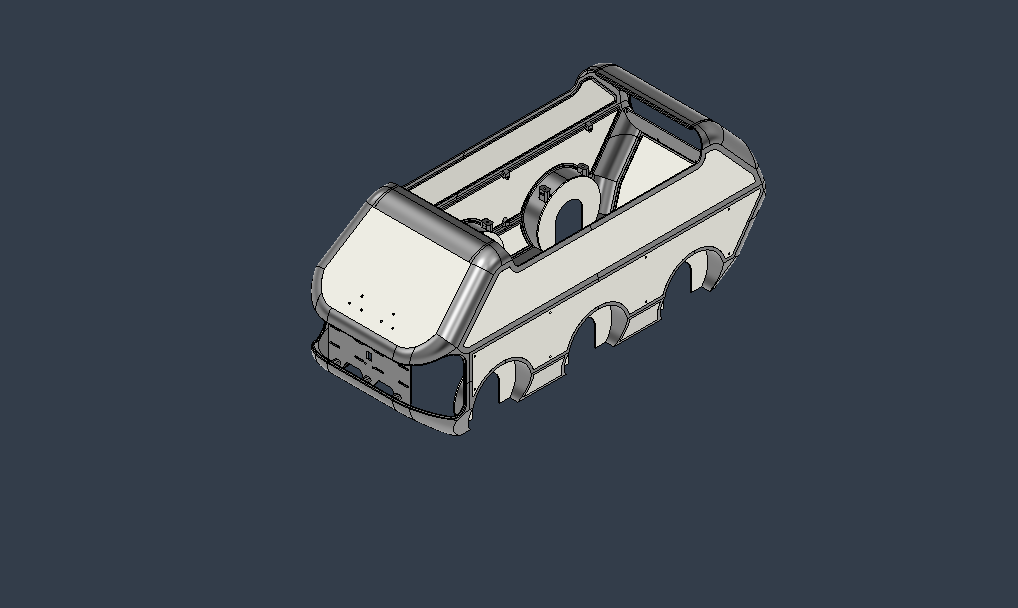
I am designing an indoor robot intended for office environments to deliver food, drinks, or other items from point A to point B. The robot will feature a six-wheeled system — four wheels will drive the robot, while two will serve as support wheels for stability. At the front, it will have a bent acrylic panel that acts as the robot’s "face." This face will include a matrix display to show animated facial expressions, helping to give the robot a friendly personality. Additionally, a time-of-flight (ToF) sensor will serve as the robot’s "eye" to detect obstacles in real time, ensuring smooth and safe navigation.
The bent acrylic face will be formed using a custom jig that I plan to design specifically for this purpose. The jig will be made from laser-cut cardboard and will use a press-fit construction, making it rigid, affordable, and easy to manufacture using tools available in the Super Fab Lab Kochi. This setup ensures consistent and precise bending of the acrylic for all face pieces.
Since the robot is designed for indoor delivery, especially in office spaces, it's essential for users to see what is inside the container. Therefore, the container will have transparent doors that provide full visibility of the contents. These doors will open completely and slide to the side—similar to the docking mechanism used in DJI drones—to give the user easy access to the objects inside.
The robot's body will feature smooth, flowing curves that give it a calming and inviting appearance. The design aims to make the robot not only functional but also emotionally appealing, with a clean and quiet presence in any office environment.
Wheel Design and Mounting
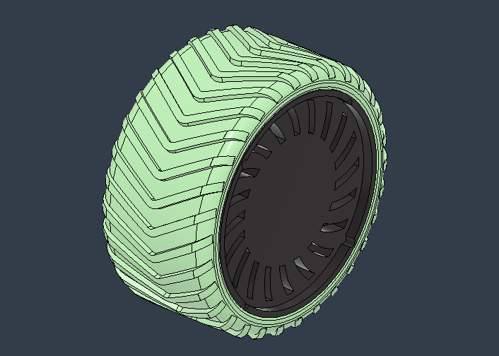
The wheels of the robot were carefully designed with both aesthetics and functionality in mind. Inspired by the wheels of RC cars, they are visually striking while offering excellent grip, making the robot capable of navigating smooth floors—even when slightly wet. The wheels will be mounted to the base of the robot using a custom-designed hub.
The hub of each wheel will be 3D printed and securely attached to the robot base, ensuring a strong and stable connection. The tire tread section will be molded using flexible PU rubber to provide superior traction and a soft, quiet ride. A reusable mold will be created to cast the PU tires—this mold may also be 3D printed and designed for multiple reuses to produce all the required wheels efficiently.
Below is the wheel design that includes the aesthetic hub and outlines the mounting system:
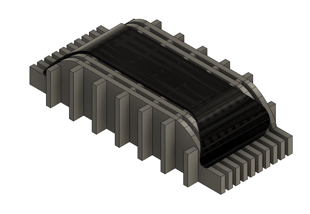
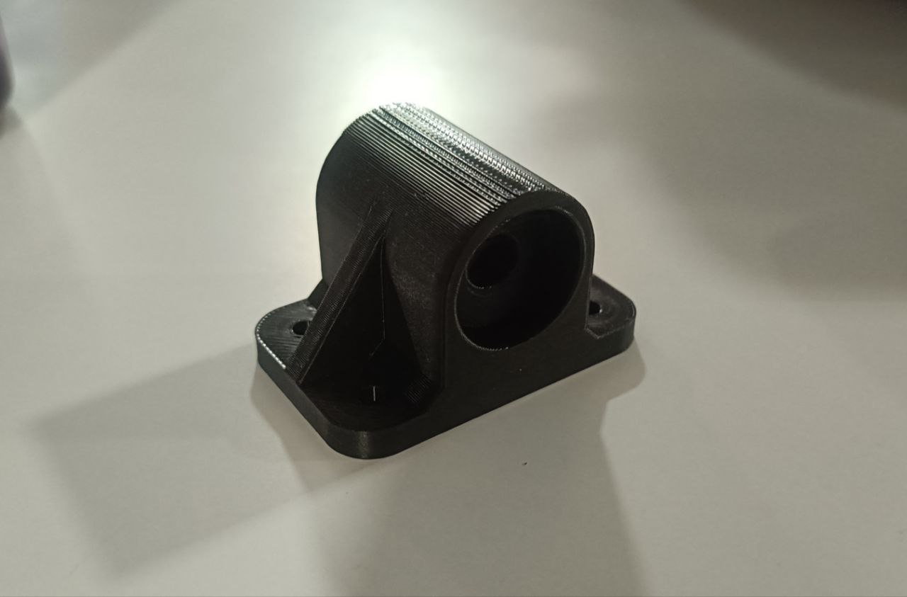
Below is the final wheel mounting mechanism:
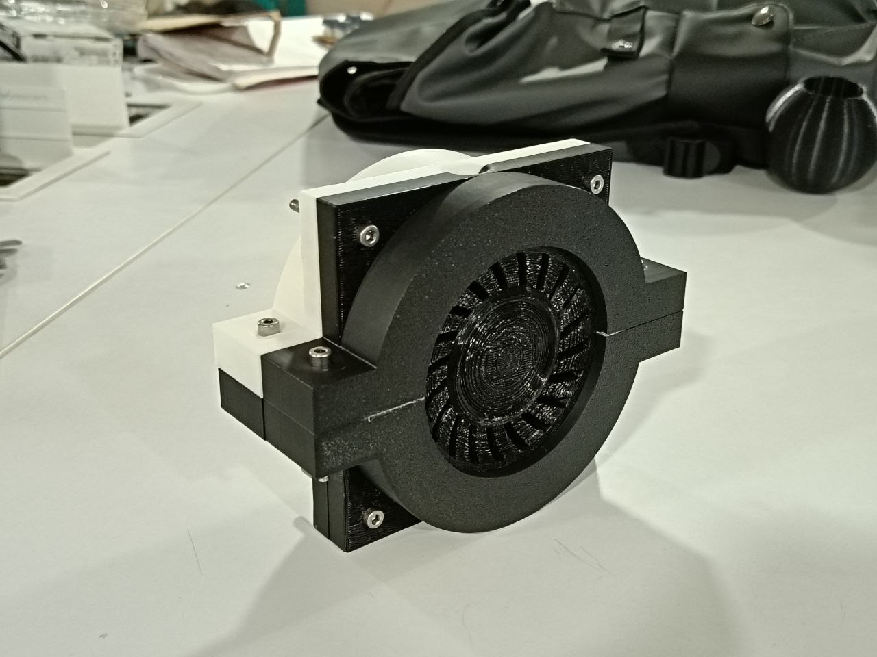
This image shows the assembled mold used to cast the PU rubber tires:
What materials and components will be used?
The materials that will be used for my project are Acrylic, 3D printed PLA & Wood. the wood will be used to make the base of the robot and the acrylic and 3D printed PLA will be used to make the body of the robot.3D printed PLA will be used to make the wheels of the the wheel mount plies etc.PCB's will be designed and made in the lab.Main micro controller with wifi will be used for communicate with the robot & smaller micro controllers will be used to control the sub systems like motors, Led etc...
Where will come from?
The materials will be sourced from the local market and the 3D printed parts will be made in the Fab Lab. All the electronics will be made from the inventory of fab lab.
How much will they cost?
The cost of the materials will be around 3000 INR and the cost of the electronics will be around 8100 INR. The total cost of the project will be around 11000 INR.
| Si.No | Component | Quantity | Price per Unit |
|---|---|---|---|
| 1 | Power Beck MP1548 | 2 | ₹ 41.00 |
| 2 | Nema 17 Stepper Motor 17HS19-2004S1 | 4 | ₹ 2,882.00 |
| 3 | Nema 17 Stepper Motor 17PM-K210-10U | 2 | ₹ 265.00 |
| 4 | Driver DVR 8825 | 3 | ₹ 94.00 |
| 5 | NeoPixel Strip | 1 | ₹ 300.00 |
| 6 | ATtiny 3216 | 2 | ₹ 112.00 |
| 7 | XIAO ESP32C6 | 1 | ₹ 555.00 |
| 8 | LiPo Battery | 1 | ₹ 2,922.00 |
| 9 | Buzzer | 1 | ₹ 50.00 |
| 10 | Matrix LED MD MAX72XX | 2 | ₹ 249.00 |
| 11 | Time-of-Flight distance sensor VL53L0X | 1 | ₹ 152.00 |
| 12 | 2Z 608 Bearing | 12 | ₹ 148.00 |
| 13 | 8mm Dia Shaft (500mm) | 2 | ₹ 284.00 |
What parts and systems will be made?
Almost every part of this project was custom-designed and fabricated by me. From the very beginning, my goal was to make as many components as possible in-house using the digital fabrication tools and techniques I had learned throughout the course. One of the first things I focused on was the tires, as they play a critical role in the robot's performance. My plan was to utilize both 3D printing and molding and casting methods. The hub of each tire would be 3D printed, while the treads would be cast using PU rubber. I designed the wheel and the required molds in Fusion 360, incorporating everything I had learned during the molding and casting week.
Another major component was the robot's body. Since it’s a large structure, my instructor advised reducing 3D printing time and cost. So, I planned a hybrid approach: the flat panels of the body would be made from laser-cut acrylic—chosen for its affordability and ease of machining—while the corner joints would be 3D printed. However, due to time constraints, there was limited opportunity for iterative testing and fine-tuning. This introduced challenges like misalignments and offset issues, especially since FDM printing was used. If I had access to SLA or SLS printers, I could have achieved much higher precision and better surface finishes.
The door mechanism was another critical aspect of the design. It gives the robot its interactive character and mechanical personality. I planned to use acrylic for the doors, with 3D-printed mounts for the stepper motors. The driving gear would also be 3D printed, while the other gears in the mechanism would be laser-cut from acrylic. By this stage of the project, I had become quite fond of working with acrylic and decided to use it for most of the moving components due to its clarity, strength, and clean aesthetics.
For the curved acrylic front face of the robot, I used a custom-built jig to bend the sheet into shape. This jig was designed to be simple yet effective, constructed from laser-cut cardboard using press-fit techniques. It allowed me to reliably shape the acrylic into a smooth curve that forms the robot's face.
In terms of electronics, the robot uses multiple custom-designed boards. The main control board—essentially the brain of the robot—is based on the XIAO ESP32C6 microcontroller. Additional boards were designed for handling specific tasks: one for LED control, one for motor control using the DRV8825 driver, and another for sensors. For obstacle detection, I chose the VL53L0X time-of-flight sensor, which is mounted on its own dedicated board. All these boards were designed and fabricated by me.
The internal storage container of the robot, where items are delivered, will be a styrofoam box. These boxes are commonly available at pharmacies, where they're used to transport refrigerated medicine. They are lightweight, insulated, and perfect for this use case.
What processes will be used?
My project involves multiple digital fabrication processes, including 3D printing, laser cutting, molding & casting, PCB milling, and CNC milling. Each process plays a vital role in the construction of different components of the robot.
CNC Milling: CNC milling will be used to fabricate the base of the robot from 12 mm wooden
sheets. This technique provides a strong, durable foundation for the entire structure.
Link: Week 07
3D Printing: 3D printing is used to create several structural and mechanical components of the
robot. These include the body panels, wheel hubs, wheel mounts, stepper motor brackets, and other mechanical
parts. This process allows for custom shapes and easy prototyping.
Link: Week 05
Laser Cutting: Laser cutting will be primarily used to cut acrylic sheets, which form the side
panels, doors, and door mechanism parts of the robot. This process is fast, accurate, and ideal for flat sheet
materials.
Link: Week 03
PCB Milling & Assembly: The electronic boards required for the robot will be manufactured using
PCB milling. This includes custom-designed PCBs for the main controller, motor drivers, and sensor interfaces.
The process will also include soldering and assembling all the necessary components on these boards.
Link: Week 08
What questions need to be answered?
Q1: Will the four motors provide enough power to move the robot efficiently?
Q2: Will the robot be able to perform a tank turn (rotate in place)?
Q3: Will the door mechanism function properly as intended?
Q4: Will the door mechanism operate smoothly with the selected stepper motor?
Q5: Will the robot be able to detect obstacles accurately using the sensors?
Q6: Will the combination of 3D printed and acrylic parts result in a visually appealing final
body design?
Q7: Will the acrylic bending process work properly and give the desired shape without
defects?
How will it be evaluated?
The project will be evaluated by testing the robot in a real life environment and see how it performs. The robot will be tested in a office environment and see how it performs in delivering food or drinks or any other item.First it will be tested in a manual mode and then if everything is working then the project will be automated.The project will be evaluated by testing the robot in a real life environment and see how it performs.And then an interface will be made for the user to control the robot.
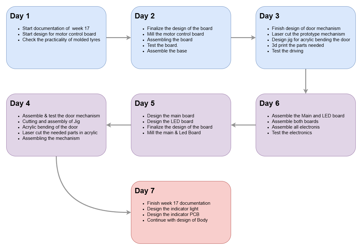
This weeks plan
Project Development Assignment
This weeks assignment was to prepare drafts of my final project summary slide (presentation.png, 1920x1080) and video clip (presentation.mp4, 1080p HTML5,minute less than 25 MB),put them in your root directory, and check that they are linked in the final presentation schedule. this is to upload some thing to the root file so that it gets updated .
Presentation Slide
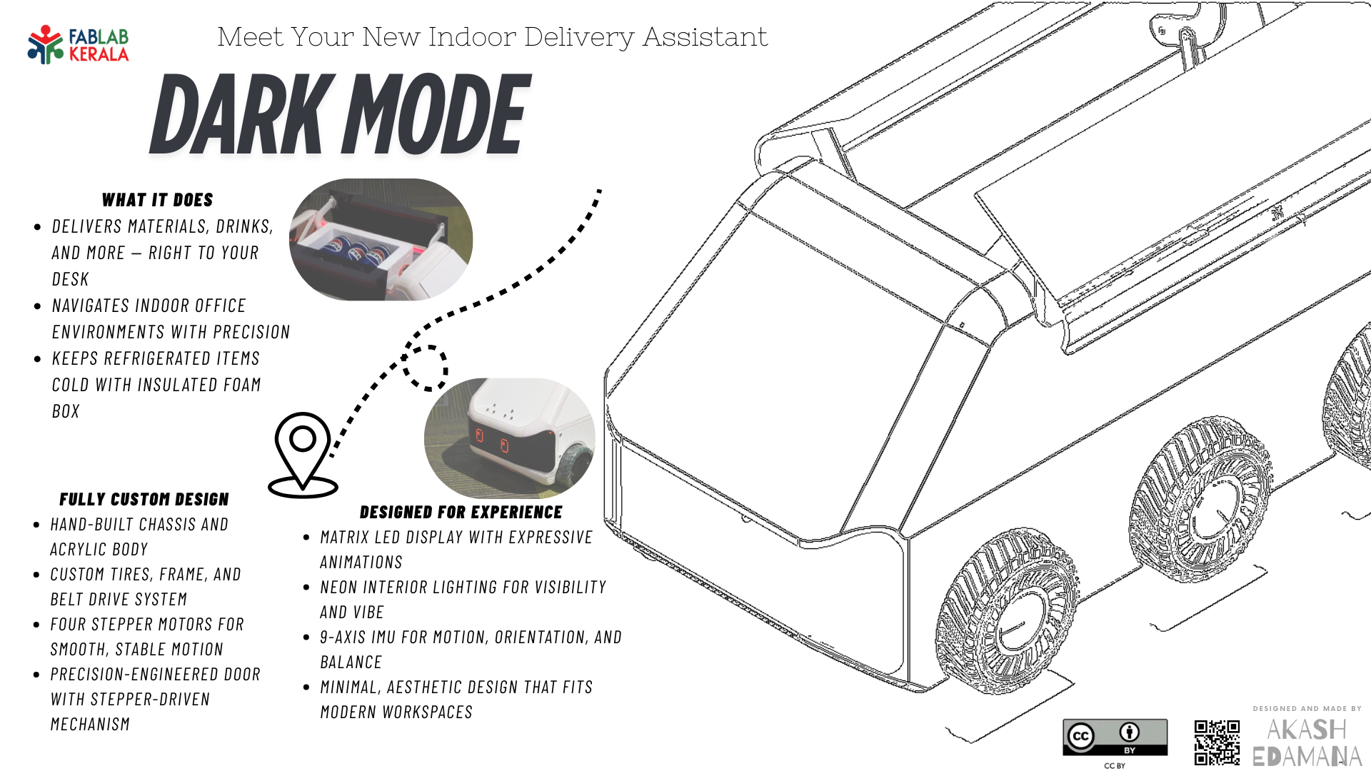
This was made using canva and the image was converted to line drawing using chat GPT Prompt : convert this image to line drawing I took the image from fusion 360 and some basic edits were made using GIMP.
Presentation video
This video was made using microsoft clipchamp, the video was imported into clipchamp and then edited using clipchamp the needed text was added and transitions were added .