Week 7
Computer-Controlled Machining
This week's tasks include both group and individual assignments. As a group, you need to complete your lab's safety training and conduct a test run to check runout, alignment, fixturing, speeds, feeds, materials, and toolpaths for your machine. Individually, your task is to design, mill, and assemble something large—approximately meter-scale. For extra credit, try assembling your project without using fasteners or glue.
Group Assignments
We have successfully completed the group assignment for this week. Our team conducted the required lab safety training, ensuring that everyone is familiar with the necessary precautions and procedures. Additionally, we performed a comprehensive test run on our machine, evaluating runout, alignment, fixturing, speeds, feeds, materials, and toolpaths. To aid in this process, we created a test jig, which allowed us to accurately measure and adjust the offset value, ensuring optimal performance and precision in our machining process.
Link : week 7 Group Assignment
Ideation
My goal was to create a fully parametric design that can be scaled to any size in CAD. From a design perspective, I wanted the chair and table to be both comfortable and practical. I aimed for a very low seating position to allow for a relaxed yet functional workspace. Additionally, I wanted the assembly to be perfect—without the need for screws or glue. The chair and table should also share a cohesive aesthetic.
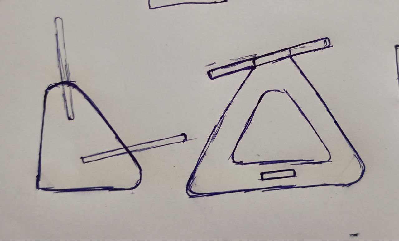
Design
for this i used the sketch i made for reference from this i made a basic idea about the design how the angles should be and then using a measuring tape took the measurements from a chair for getting a rough value of the seat width etc..
Then from this I made a basic sketch with measurement's angle etc.
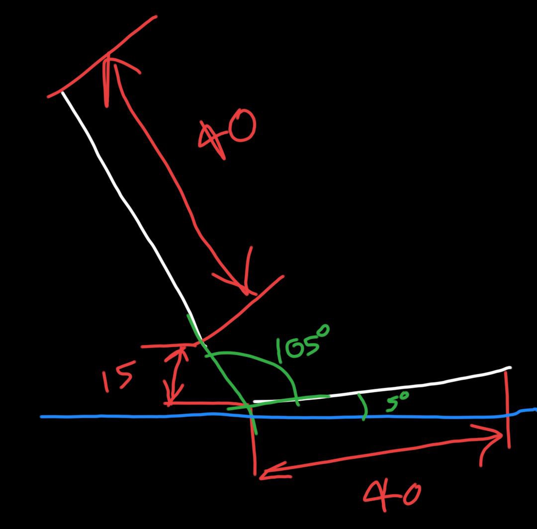
Using these dimensions i made a 3D model in fusion360 with every measurement connected to a parameter for this project for equal scaling of all the dimensions I multiplied every dimension with a parameter called scale, so when scaling only one value have to be changed for reducing the scale of the entire object also i have added a separate parameter for material thickness, offset, slot width and tool diameter .

After this I made the CAD model, sorting out the parameters were a bit challenging but after some trial and error i was able to sort it out ,The new feature in fusion i.e., auto dimensioning was very useful.
After this using the arrange tool in fusion I arranged all the components in a specified area I took the measurements from the work piece the also selected a plane where I want to arrange the components then made the projection of all the components into a plane and exported the sketch as DXF

Laser cutting
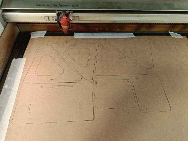
Then next step was to make a prototype from cardboard so I changed the scale and thickness parameter and then exported the DXF and then imported the file to ink scape and then changed the color and thickness of the line since i am using the trotec laser cutter then i made the cut
There i had to do multiple iterations since I made some mistakes in the the off set and there were some design issues i had to solve to increase the stability of the table and then I made a all changes and made the final cut of the design
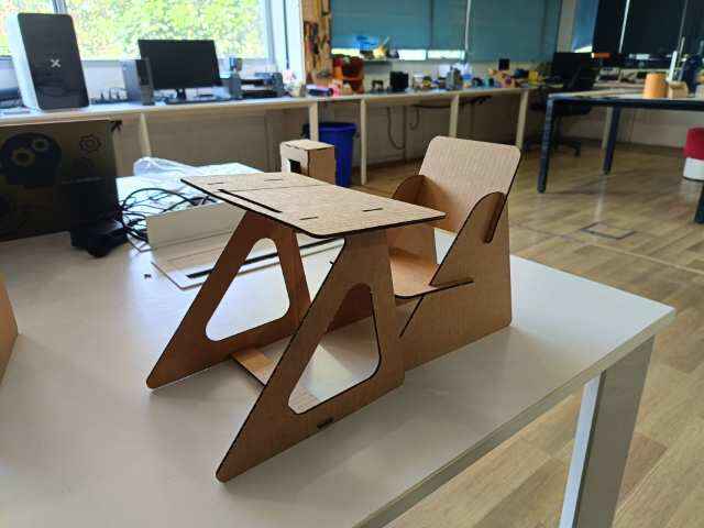
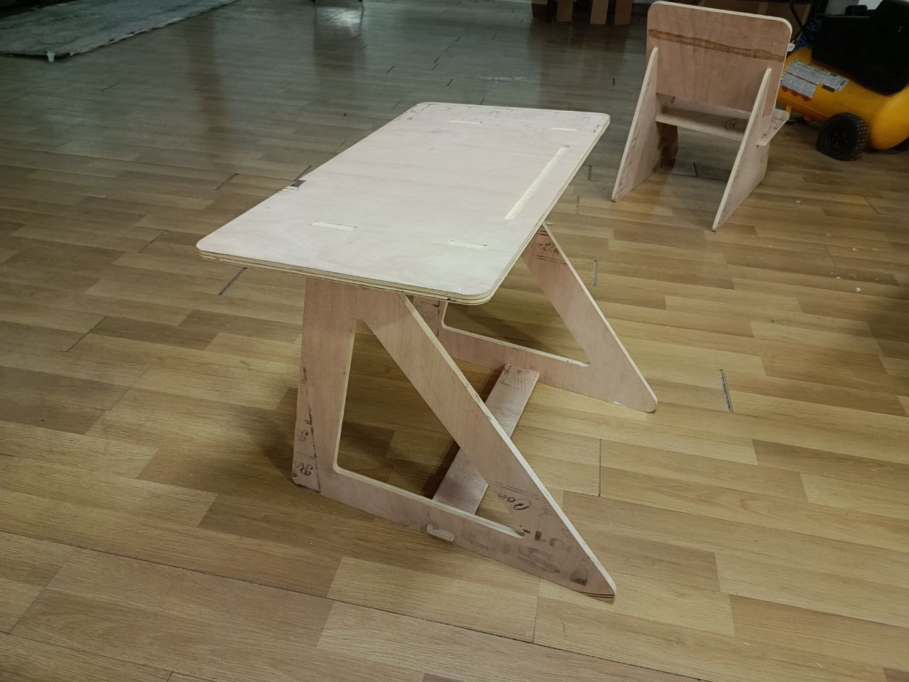
Then I assembled it to get the final assembly everything was looking good, But for adding more stability i added one more cross member to increase the stability of the table
ShopBot PRSalpha (PRS5 Alpha) CNC Machine
The ShopBot PRSalpha is a high-performance CNC router designed for industrial-grade precision and power. It is ideal for both prototyping and full-scale production work, capable of cutting, carving, drilling, and machining a wide range of materials including wood, plastics, aluminum, and composite materials.
Website Link : ShopBot PRS5 Alpha
Key Features
- High-Speed, High-Torque Motors: Equipped with closed-loop alpha stepper motors that provide fast and accurate motion with reliable positioning.
- Robust Frame: Made from heavy-duty welded steel to ensure durability and vibration-free operation.
- Cutting Area: Available in multiple sizes. The "5" in PRS5 often refers to a 5-foot wide table. Common configurations include 96" x 48" or custom sizes.
- Spindle Options: Supports 2.2kW to 5HP spindles depending on configuration, suitable for heavy material removal and high feed rates.
- Repeatability: Approximately ±0.002 inches (±0.05mm), suitable for precise machining tasks.
- Toolpath Compatibility: Compatible with standard G-code and uses software like VCarve Pro, Aspire, and ShopBot’s own control software.
V Carve
VCarve is a CAD/CAM software developed by Vectric for CNC routing, engraving, and sign-making. It allows users to create precise toolpaths from 2D designs and supports various machining techniques such as V-carving, pocketing, profiling, and inlays. The software is widely used in woodworking, furniture making, and decorative carving. It offers design tools for importing DXF, SVG, EPS, and bitmap files, along with toolpath simulation to preview cuts before machining. VCarve also includes efficient nesting features to optimize material usage. Available in VCarve Desktop for smaller CNC machines and VCarve Pro for larger projects, it is user-friendly and suitable for both hobbyists and professionals.
Link : VCarve〡Vectric
- First I imported the DXF file int v carve and then as the first step set dimensions of the materials like Height, Width and length
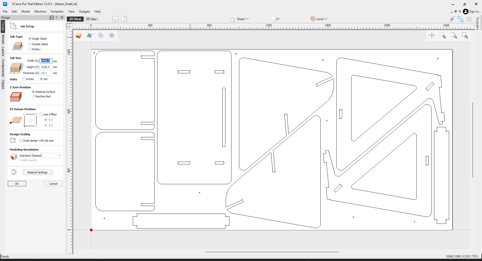
- Then I arranged all the parts properly with proper spacing as required
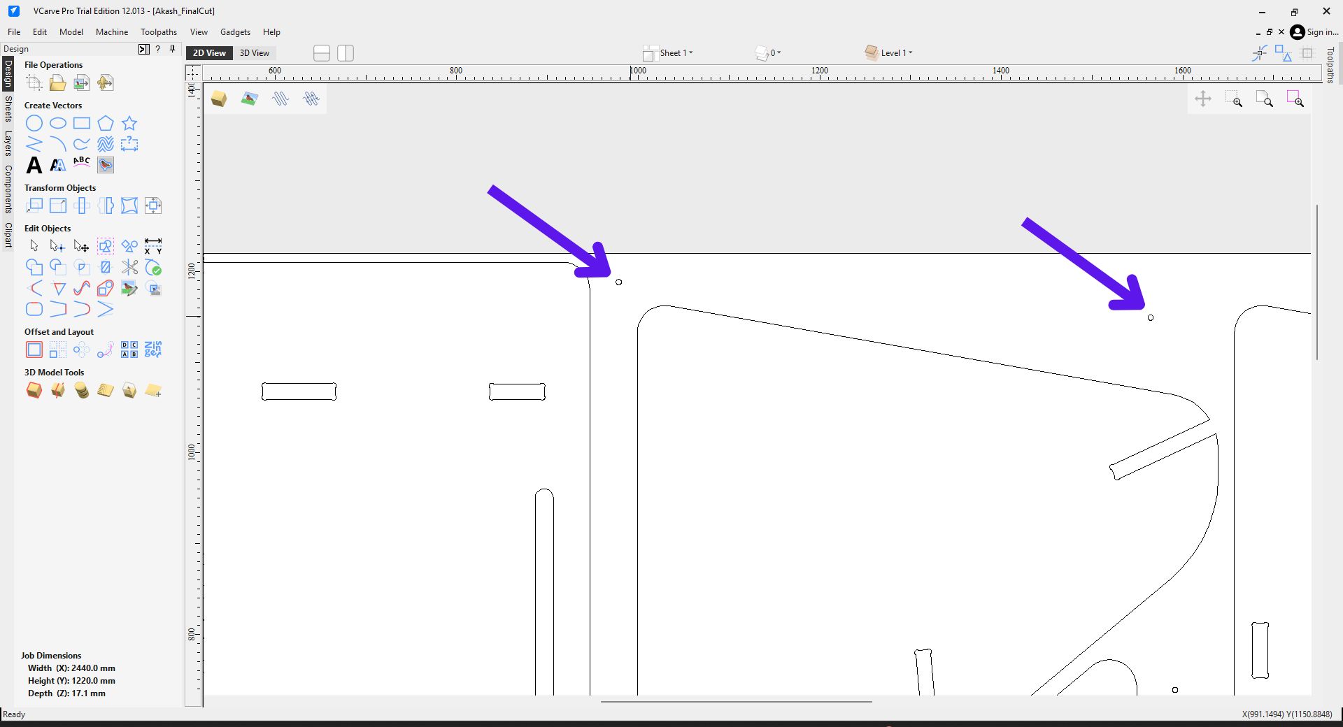
- Since I am going to use the whole sheet I had to properly fix the work piece to the sacrificial layer so I had to use screws but to prevent the tool from hitting the screw i had to put some marking in the workpiece so i manually added some circles in the design which does not conflict the output cut
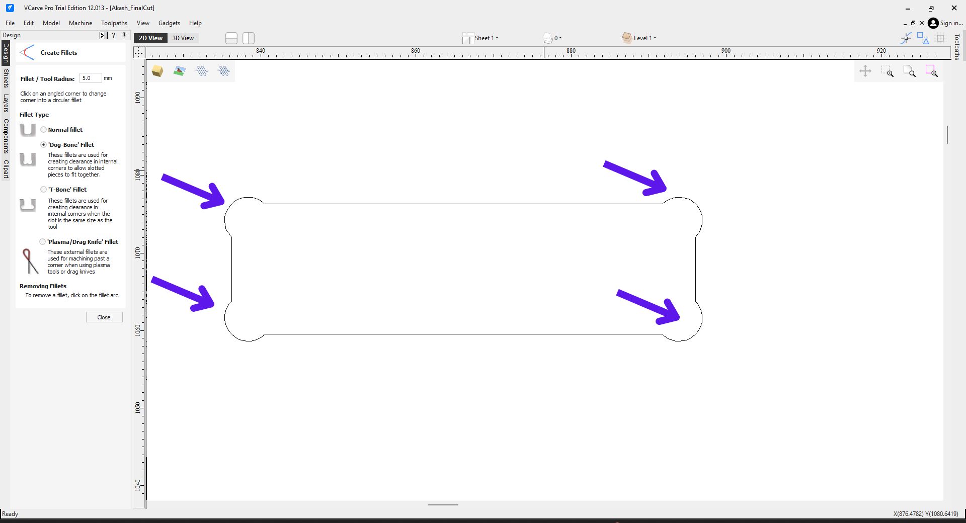
- Then the next step was to add dog bones in the design so from the left tool bar using the fillet tool manually add dog bones in all the corners, also set the tool radius as the fillet radius.
- And this is the final design for cutting
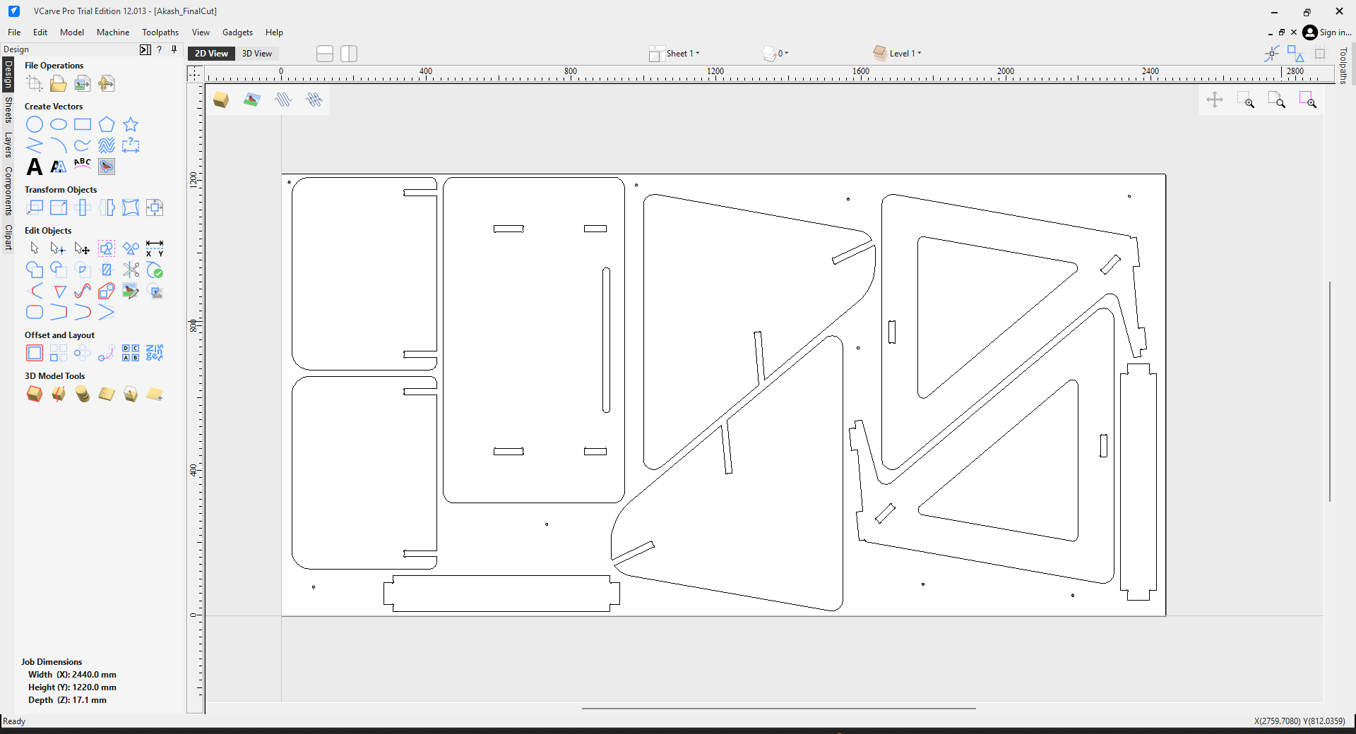
Tool Path
- The first step was to make the pocket in the design for this select the part where the pocket have to be made then open the pocket tool from the right tool bar the set the depth of the pocket and set the value from the left tool bar then press the calculate button

- Then the next step was to add the slots in the design here I selected the pats where the sketch have to be made then from the left tool bar from the tabs section using the edit tab button then added the tabs manually also set the cut depth as 17.5, the actual thickness of the material is just 17.1 but due to some errors with the Z axis of the machine i had to add .4 mm to it the final value s 17.5 mm and also make sure to set the machine vector as inside so the material will be removed form inside the lines.

- Then the next step is to make the internal cut to remove material from the from inside the leg so I selected the line where the path have to be generated the tool path using 2D plot tool and selected internal cut and then calculated it.

- Then next step is to generate the path for the final external cut here I using the 2D profile i repeated the same process here too but rather than internal cut i used external cut then hit calculate, I also added tabs.

- Now file is ready for cutting
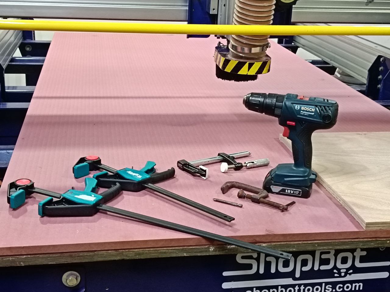
- The next step is setting up the work piece on the table for this all the tools in the image can be used.
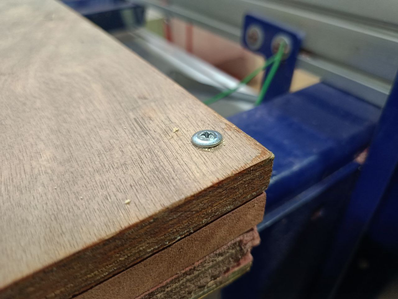
- In my case I used screws to properly fix the work piece to the bed.
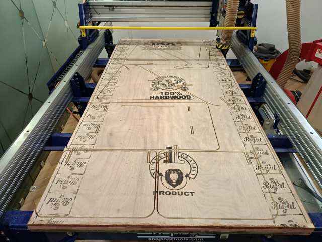
- Then I proceeded for cutting it took more than 2 hours for cutting
- And after hours of cutting the cutting was finished and this is the final result
Issues
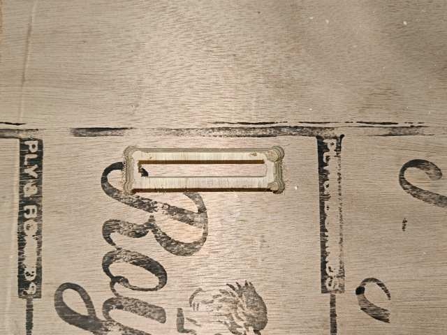
In some places the cut was not properly cut so I had to remove it manually
Post processing
Safety
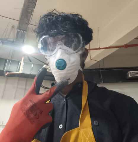
Safety is an important factor during assembly there is a high chance of getting injured during wood working, so proper safety measures like shoe, gloves, masks, eye protection etc. should be there for more details about safety visit the group assignment page from the top of this page.
Post processing
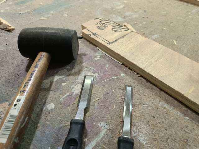
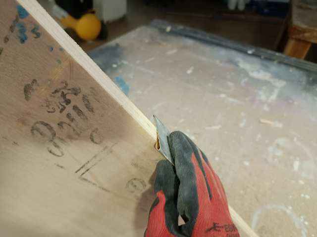
- The first step in post processing was to remove all the unwanted material and tabs using the chisel and mallet.
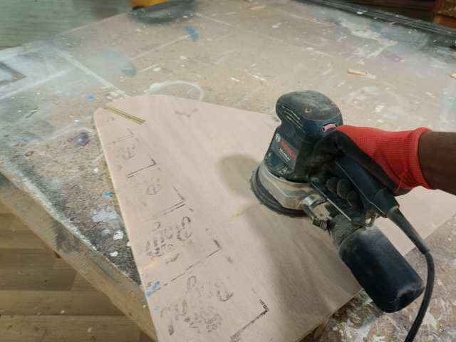
- The next step was finishing the surface using the sanding machine during this most of the burrs will be removed
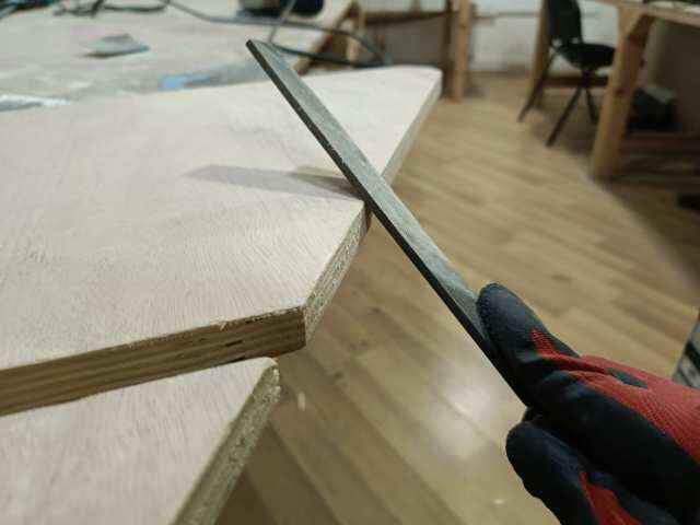
- After that i used a a hand file to smoothen the corners and to remove any burs that may be left after sanding
- After this i moved to the final step of post processing that is the final sanding i used a sanding paper to remove any left material after sanding
Assembling
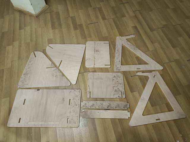
I was very exited to reach this step it was the most exited after finishing all the post processing for all the parts I proceeded to assembly for this i took from a second person to assist me in the assembly.
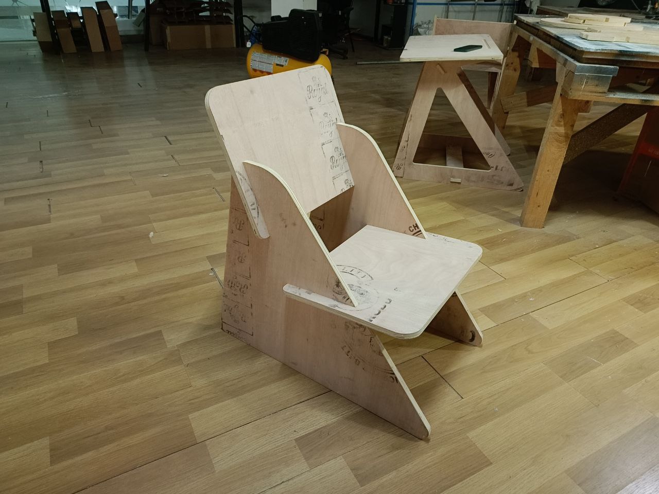
Since the design was press fit no fasteners or glue was used for the assembly using a mallet everything was put into place. It was very interesting to build something that is completely press fit it was very tight so disassembling will be very challenging and due to the low quality of the wood there was a very high tendency for the wood to split while it was being assembled using the mallet.
Final result
This is the final output in the table i had addle some extensions on the connecting members to that the table remains stable and it have been better if the height of the table was a bit low rest everything was looking good everything was working properly as it was supposed to work and i wa very happy with the result obtained.
.jpg)
Instructor evaluation 😁😁
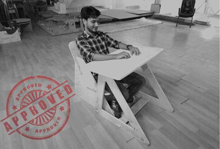
my table & chair was evaluated by evaluator Mr. Saheen and from his expression I understood that he was satisfied with the results
Conclusion
In conclusion, I have successfully completed all the tasks for this week. As a group, we conducted the required lab safety training and performed test runs to evaluate runout, alignment, fixturing, speeds, feeds, materials, and toolpaths for our machine. Individually, I designed, milled, and assembled a meter-scale project, ensuring precision and functionality. Additionally, I achieved the extra credit challenge by assembling the project without using fasteners or glue.

