9. Input Devices
Assignments
Here you can find a recording of the lecture from the 19th of march.
This week's assignments and learning outcomes, see here:
Group assignment:
- Probe an input device(s)'s analog levels and digital signals.
- Document your work on the group work page and reflect on your individual page what you learned.
You can find the documentation for our group assignments here.
Individual assignment:
- Measure something: add a sensor to a microcontroller board that you have designed and read it.
Questions to be answered/from Nueval:
Have you answered these questions?
- Linked to the group assignment page
- Documented what you learned from interfacing an input device(s) to your microcontroller and optionally, how the physical property relates to the measured results.
- Documented your design and fabrication process or linked to the board you made in a previous assignment.
- Explained the programming process(es) you used.
- Explained any problems you encountered and how you fixed them.
- Included original design files and source code.
- Included a ‘hero shot’ of your board.
Link to group page
Here you can find the documentation of our group assignment.
Hero shot
Hero shots from individual assignments
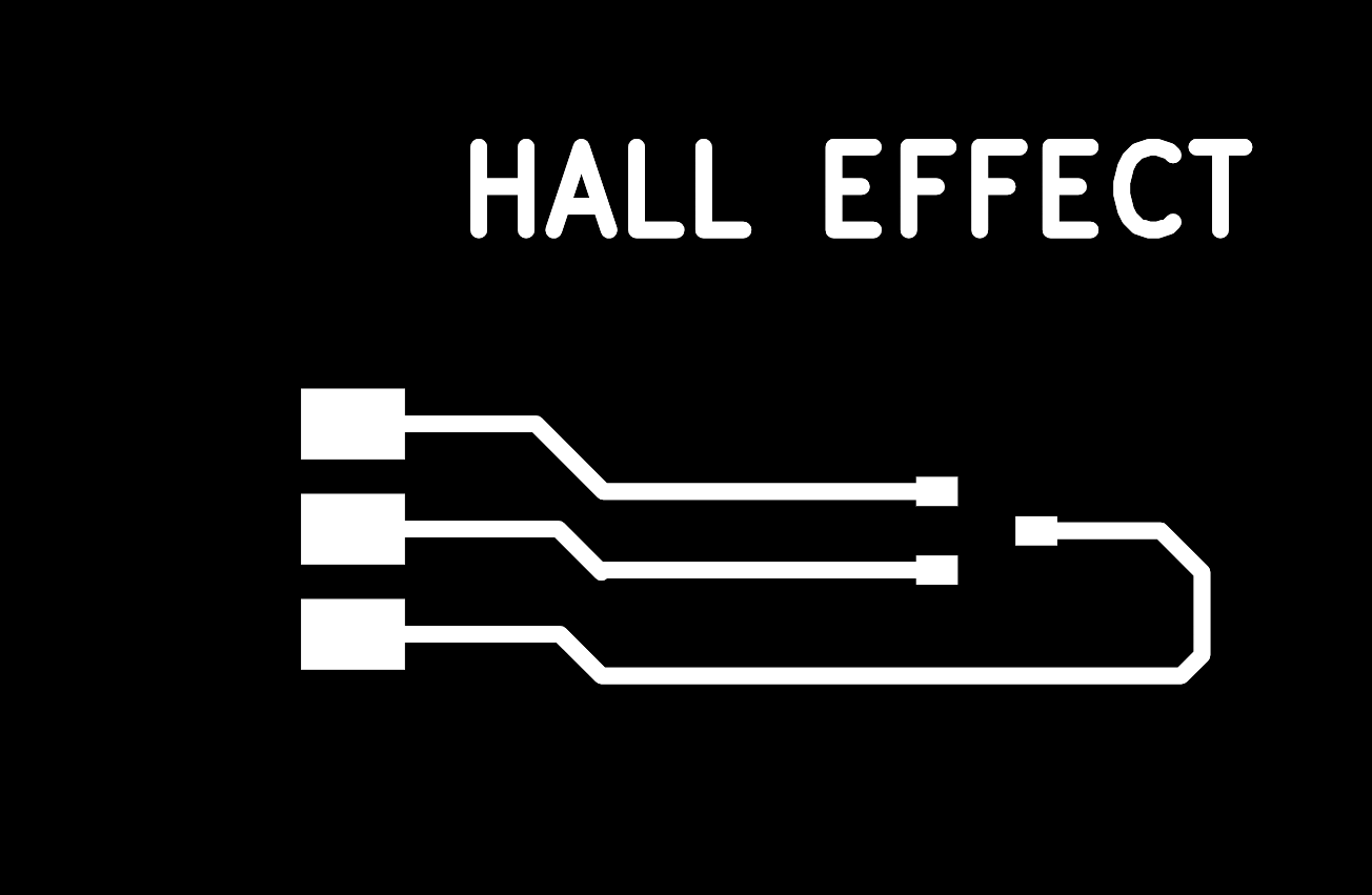
In think pcbs are beautiful when the daylight shines through them. For that reason I decided to add this image to my hero shots.
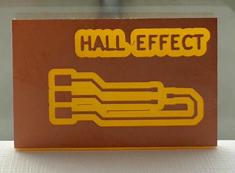
Here you can see the Hall effect breakout board that I made.
Hero shots from group assignment
Using the plotter in Thonny
Using the Oscilloscope
Summary
In the group assignment we all tested Hall effect sensors with different breakout boards and used the Oscilloscope to read analog and digital signals.
You can find the documentation for our group assignments here.
In the individual assignment I decided to go for the XIAO board created by Adrián Torres. Then I wanted to try out some input devices, according to the assignments of the week.
Work process detail
What to do this week
What to do this week
This week I could have used the Raspberry Pi Pico board that I made in week 08, added some pins and used it with input devices, but I wanted to try to create the XIAO board that Adrián Torres created. Then the plan was to add extra LED and another button and then try out input devices.
Using labels in Kicad
Using labels in Kicad
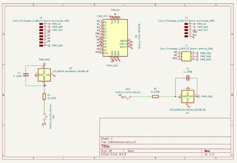
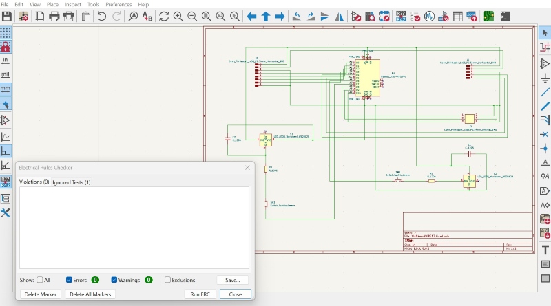
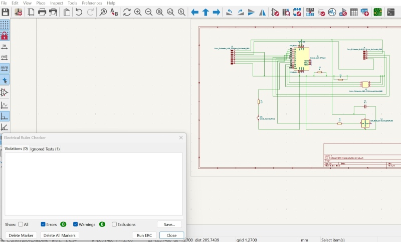
I used Kicad and began by adding components in the Schematic editor. Andri Sæmundsson shows how to use labels in this video here and I wanted to try it out. It did not go well and there was a long list of errors.
Using wires in Schematic editor
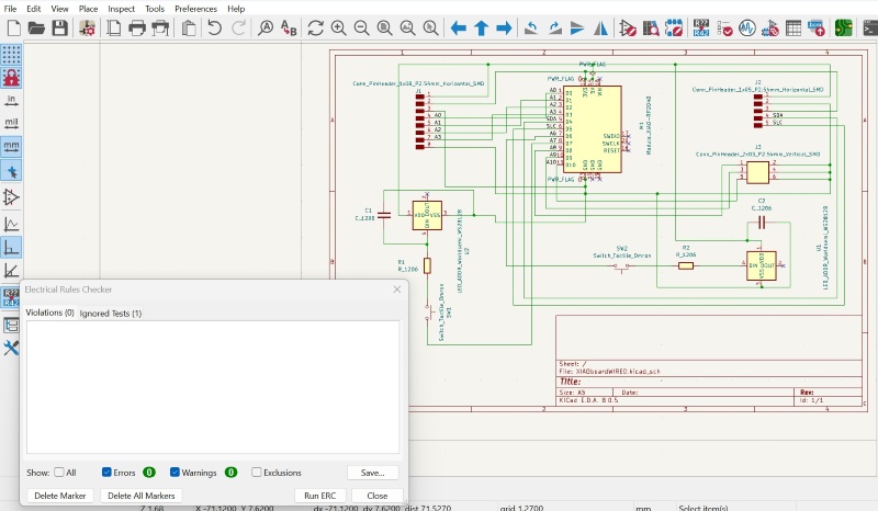
I decided to see if the board was setup in the right way by using wires instead of labels, so I saved a copy and used wires. That went well and there were no errors. It was good to see that everything was connected the right way, so my understanding on this is getting better.
Could not open the Schematic design in PCB editor
When I saved a copy of the design, it looks as if I only saved a Schematic file and I couldn't open it in the PCB editor. After trying for some time, I decided to create a new drawing. It went well and there were no errors.
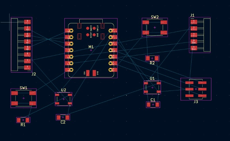
Crossings in PCB editor
Complications in the PCB editor
The design looked complicated in the PCB editor and it took a long time to arrange and rearrange the components in the PCB editor, trying to create tracks that were not crossing each other. I had added extra LED and button to increase the possibilities with the board and also because I didn't want to just copy the design from Adrián Torres.
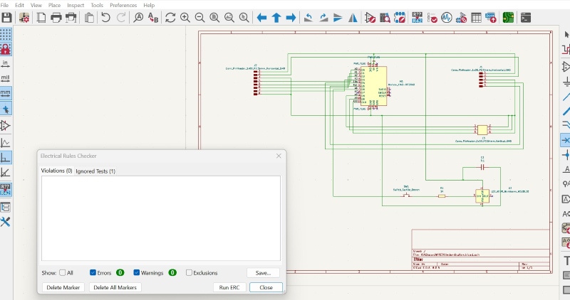
Simplifying the design
Simplifying the design
In my attempt to do something more than just copying the XIAO board from Adrián Torres I made the board too complicated for me at this time. Hopefully I will get better at creating designs like this later on, but right now this puzzle was taking too much time this week. I told Svavar Konráðsson that I was having problems with connections and he adviced me to follow what Adrián had done. There was little time left to work with the input devices, so I decided to simplify the design and use only 1 LED and 1 button.
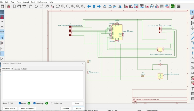
The problems with wiring continued, even though the design had been simplified. I tried to place the components in different places and rotating them, but nothing worked.
Using 0 resistors
I added 0 resistors to the design in the Schematic editor, as Adrián Torres had done, but it just didn't seem to be enough for me to solve the puzzle. Everything seemed so simple in Adrián's design, but when I tried to do the same setup, there were still problems. One of the problems was that even though I added the 0 resistors to the design, the program would not allow me to connect the wires to it.
Hall effect sensor breakout board
A Hall effect sensor
According to the informatin here a Hall effect sensor detects a magnet when it is near. It can f.ex. be used with position sensors, rotary/shaft encoders and switches. I decided to create a breakout board for a Hall effect sensor and measure how it would respond to magnets.
A breakout board for hall effect sensor
I saw that Adrián Torres created a breakout board for a hall effect sensor and I used his documentation as a reference.
Files for hall effect sensor breakout board
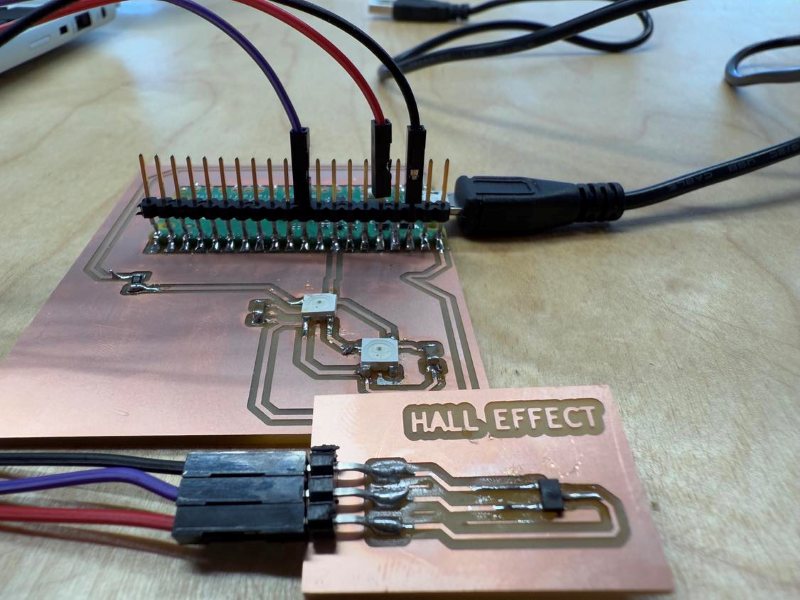
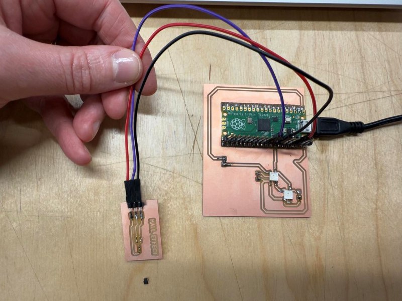
Connecting and programming the hall effect sensor
Connecting and programming the hall effect sensor
Svavar Konráðsson told me about this website that shows how to use analog input and to program a hall effect sensor. I followed these directions on how to connect the breakout board and I copied the code from this site. You can see the code here below:
Code snippet for Hall effect sensor
from machine import Pin, ADC
from time import sleep

pot = ADC(Pin(26))

while True:
    pot_value = pot.read_u16()  #read value
    print(pot_value)
    sleep(0.1)
File for programming the hall effect sensor
Hall effect - programming in Thonny
Problems - board overheated
Board overheated
When I plugged the board in, it overheated very quickly. I could see smoke drifting up from the board and when I lifted it the Hall effect sensor fell off! So frustrating!!! Well, nothing to do but to continue and I souldered the sensor to the board again.
Doppler radar
Doppler radar
I did this project in week 11 but I am adding this documentation on the Doppler radar to input devices here. I begin by explaining which board I used and then I explain everything about the Doppler radar.
The board I designed and produced
I produced a board in week 08. In previous projects I had been using a Raspberry Pi Pico without wifi, but now I needed a microcontroller with a wifi connection in the networking and communication assignment, so I soldered a Raspberry Pi Pico W on it. I used this microcontroller as the client.
Then I used another Raspberry Pi Pico W as a server in the assignment and I also used it with the Doppler radar. I did not want to solder it to a board because maybe I want to use it on another board in the final project, so I decided to solder pins to it and only use three small points to do that. Then I should be able to add it to another board later on.
![]()
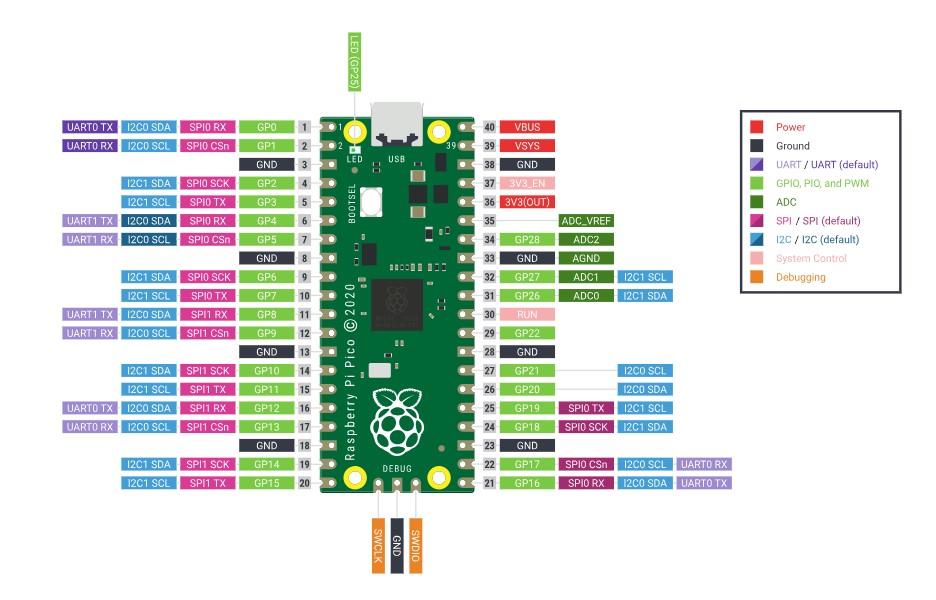
Pinout and information for Raspberry Pi Pico W
Pinout and information on the Raspberry Pi Pico W
According to the information here, the Raspberry Pi Pico W has a single-band 2.4GHz wireless interface (802.11n). It's main features are:
-
Single-band 2.4GHz, wireless interface (802.11n)
-
WPA3
-
It has a soft access point for up to four clients
-
Bluetooth 5.2
You can find the pinout for the Raspberry Pi Pico W here.
Pinout (image from here):
Doppler radar
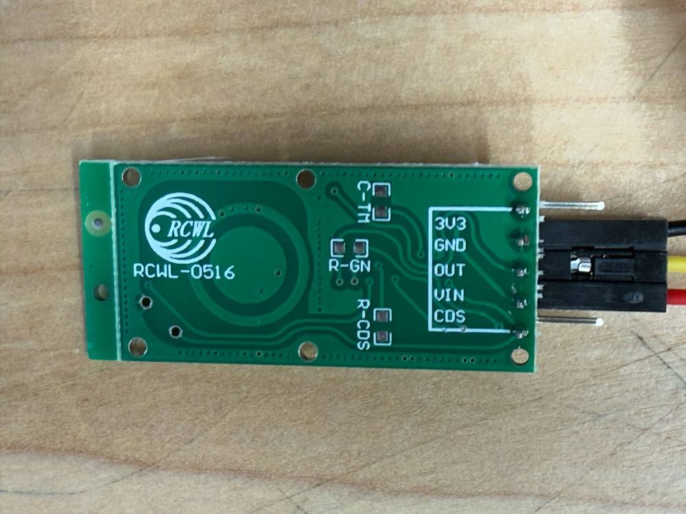
RCWL- 0516 Doppler radar
I began by learning how to use a Doppler radar (or RCWL motion detector) because I want to use it in my final project and time is running out. Here you can find information on it. It is a microwave radar sensor and has a high sensitivity and can detect movement with the range of 7m. It can detect movement in 360°. A built-in oscillator sends out a microwave signal and when these waves hit an object, they are reflected and their frequency is measured by the Doppler radar. When an object moves the frequency changes.
Directions for Doppler radar
I followed these directions when connecting the Dopple radar to the Raspberry Pi Pico W. I only used three of the pins on the Doppler radar. I connected them this way:
| Doppler radar | Raspberry Pi Pico W |
|---|---|
| OUT | GPIO 26 |
| VIN | VBUS (5V) |
| GND | GND |
Code snippet for Doppler radar
Code used to control the Doppler radar
I used the code from these directions. I did not include the Led that was in the original code and I changed the number of the sensor pin. Here below is the adjusted code that I used.
# Complete project details at https://RandomNerdTutorials.com/raspberry-pi-pico-rcwl-0516-micropython/

from machine import Pin
import time

# Pin numbers for LED and sensor
led_pin = 21
sensor_pin = 26

# Set the LED pin as an output and the sensor pin as an input
led = Pin(led_pin, Pin.OUT)
sensor = Pin(sensor_pin, Pin.IN)

# Initialize state variables
state = 0
val = 0

while True:
    val = sensor.value()  # read sensor value

    if val == 1:  # check if the sensor is HIGH
        led.on()  # turn LED ON

        if state == 0:
            print("Motion detected!")
            state = 1  # update variable state to HIGH
    else:
        led.off()  # turn LED OFF

        if state == 1:
            print("Motion stopped!")
            state = 0  # update variable state to LOW

    # Add a small delay to avoid constant checking of the sensor
    time.sleep(0.1)
Video showing Doppler radar working
Doppler radar
Learning outcome
The Hall effect sensor and the Doppler radar
Both the Hall effect sensor and the Doppler radar are input devices that sense something in the environment. The Doppler radar can detect movement in 360°. A built-in oscillator sends out a microwave signal and when these waves hit an object, they are reflected and their frequency is measured by the Doppler radar. When an object moves the frequency changes. On the other hand, the Hall effect sensor detects a magnet when it is near. Both of these input devices can be used to control devices. As I mentioned before, according to the information here, a Hall effect sensor can f.ex. be used with position sensors, rotary/shaft encoders and switches.
You can see an example of how I used the Doppler radar is used to control Neopixels here when I was working on my final project.
Soldering getting better
Finally, I am getting better at souldering! In this video you can see that I am trying to do my very best when souldering pins to my Raspberry Pi Pico board.
Focus on souldering
Design files
Kicad - only Schematic file
Here is the file that I was having problems with and could not import the design into the PCB editor.
Kicad files for board with two LEDs and two buttons
Here you can find the design files for the wired board with two buttons and two LEDs.
Kicad files for board with 1 LED and 1 button
Here you can find the Kicad files for the simplified board with 1 LED and 1 button.