Dr4wbck
My contribution:
- Files can be downloaded from the cloud in the "files" file.
- 1x Bearing
- 6x Screw M3
- 5x Screw Nut M3
- 1 rubber band
Group Assignment
Progress documentation
- Initially, I was presented with 2 options: Pico V2 milling machine and the Axidraw drawing machine.
Originally I chose the Pico V2 variation and proposed a variation based on injections, electric engraving pens, a lead screw + handwheel, and these little motors. Top it off with line following system and a automatic z-axis and it Basically comes down to a simple carver.
It turns out my group mates had already decided exactly what they wanted to do. I did not agree on that production strategy, so I switched to the AirDraw team. Our machine is called "dr4wbck". - I was given the task to design a penholder based on the Urumbu, research about Capston Drive, and get familiar with he Axidraw machine.
- When I was strong enough to come to the lab a few days later, I received an update on the current status of the project and the basic idea.
I was introduced to the wiki page, where they were tracking their progress, references, and ideas.
I officially accepted the task of designing the nozzle and was told to use the Flexture design proposed by the Urumbu to design the z-Axis and a pen holder design from our supervisor.
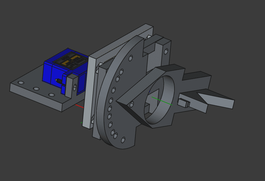
With that in mind, here is the list of new requirements:- Use Flexture to design z-Axis. The servo motor that we will use is a generic SG90 Micro Servo Motor
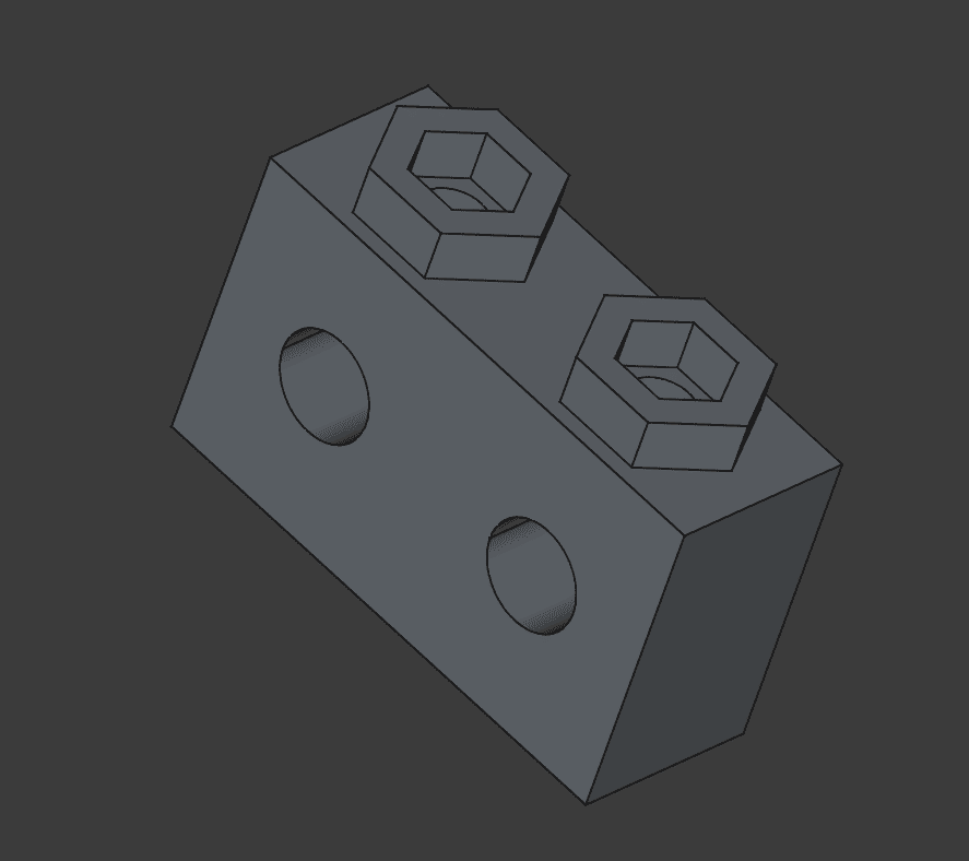
- An angle setter for the pen (this one was kinda self imposed)
- Pen holder according to my instructor's previous design. It should be able to hold any size of pens
- Use FreeCAD
- Use exclusively components from the lab and make it quick (deadline: 2 days) and learn sth
- New nozzle design:
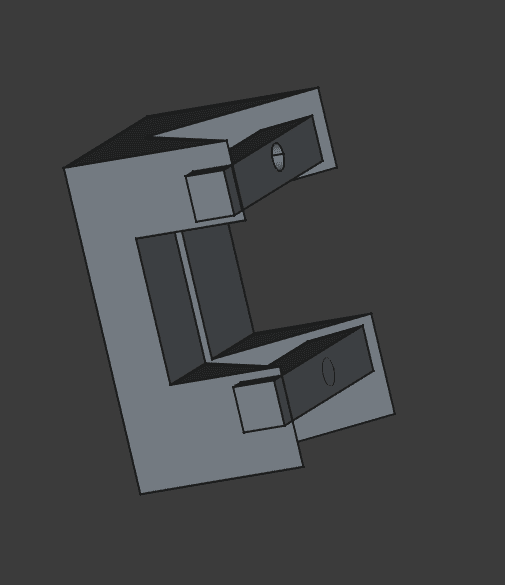
Development of the pen holder tip. From left to right. To close V3 take a rubber band and securely attach it on both sides. 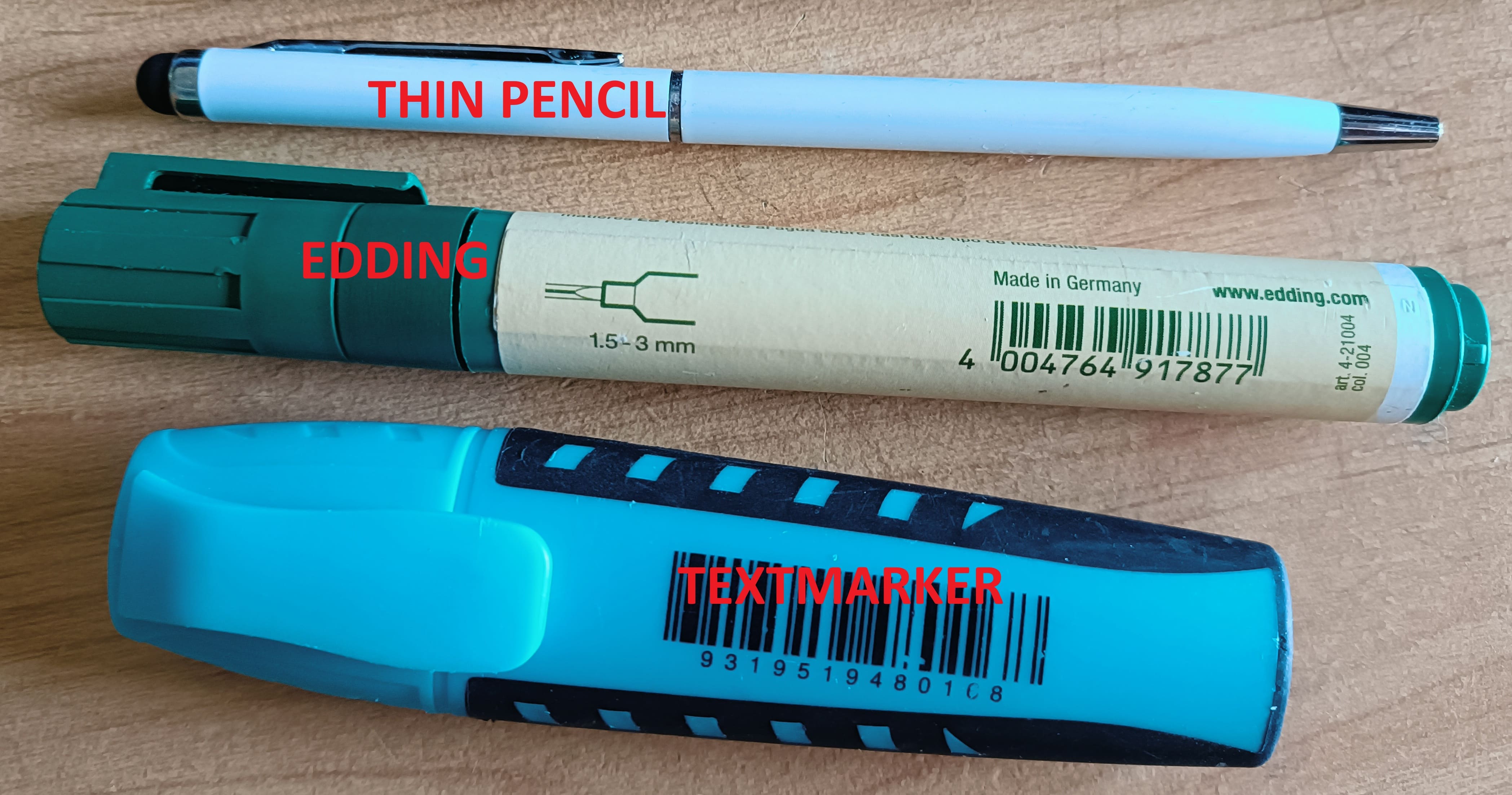
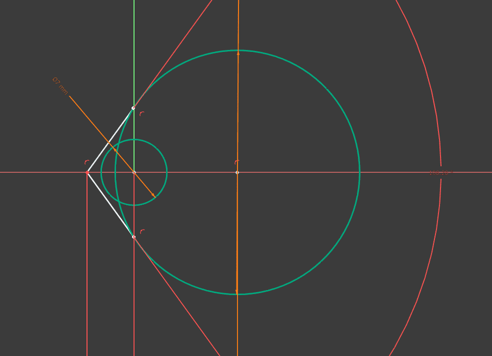
left: pens used for measurements. Right: Resulting required angle for pen holder v-shape. Result: 108.23° -> 110° 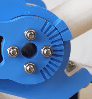
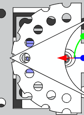
Angle set mechanism. Left: inspiration for the angle setting mechanism I used our instructor's flexture mechanism from his 3D3 machine, as it is exactly the same use case and program as that project. The file is called "pen_holder_flexture"
For the assembly, I found a 3D model online.
- Fixed some last issues before testing:
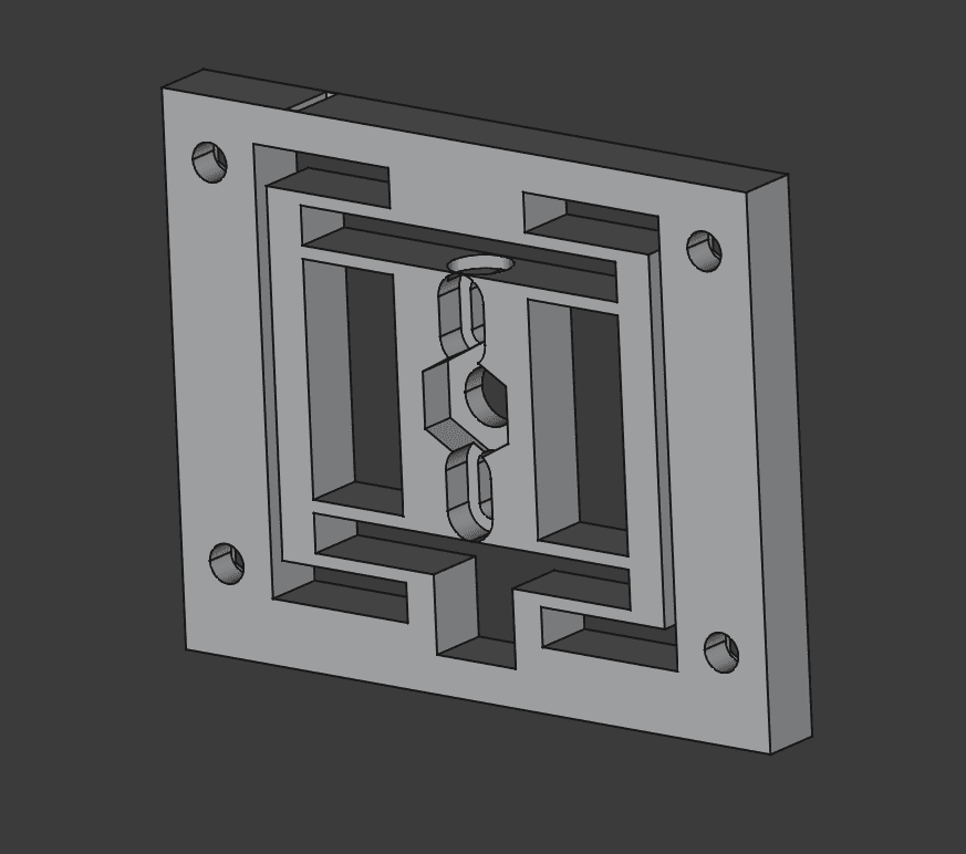
Flexture design can not be attached better. Left: our instructor's original design 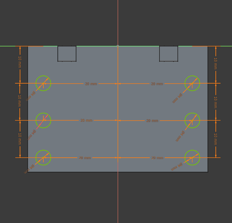
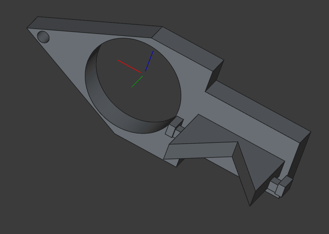
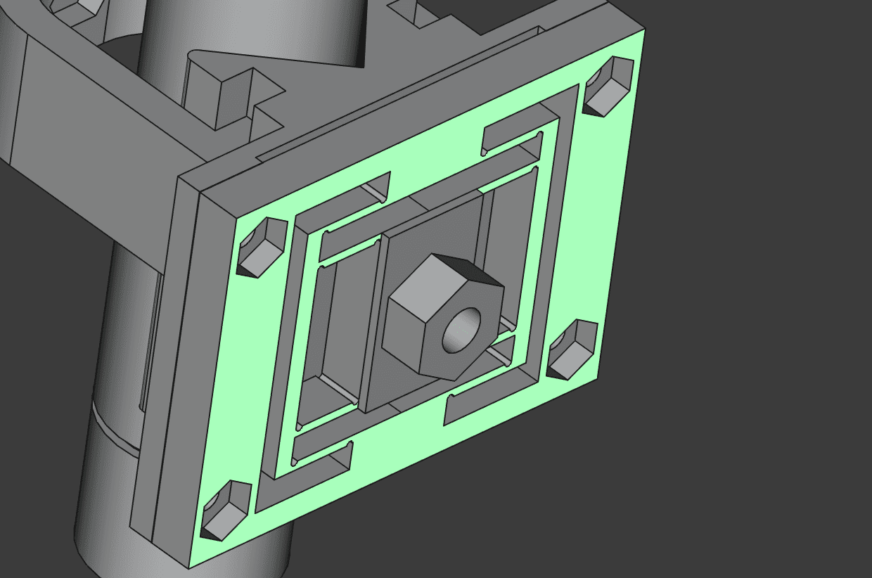
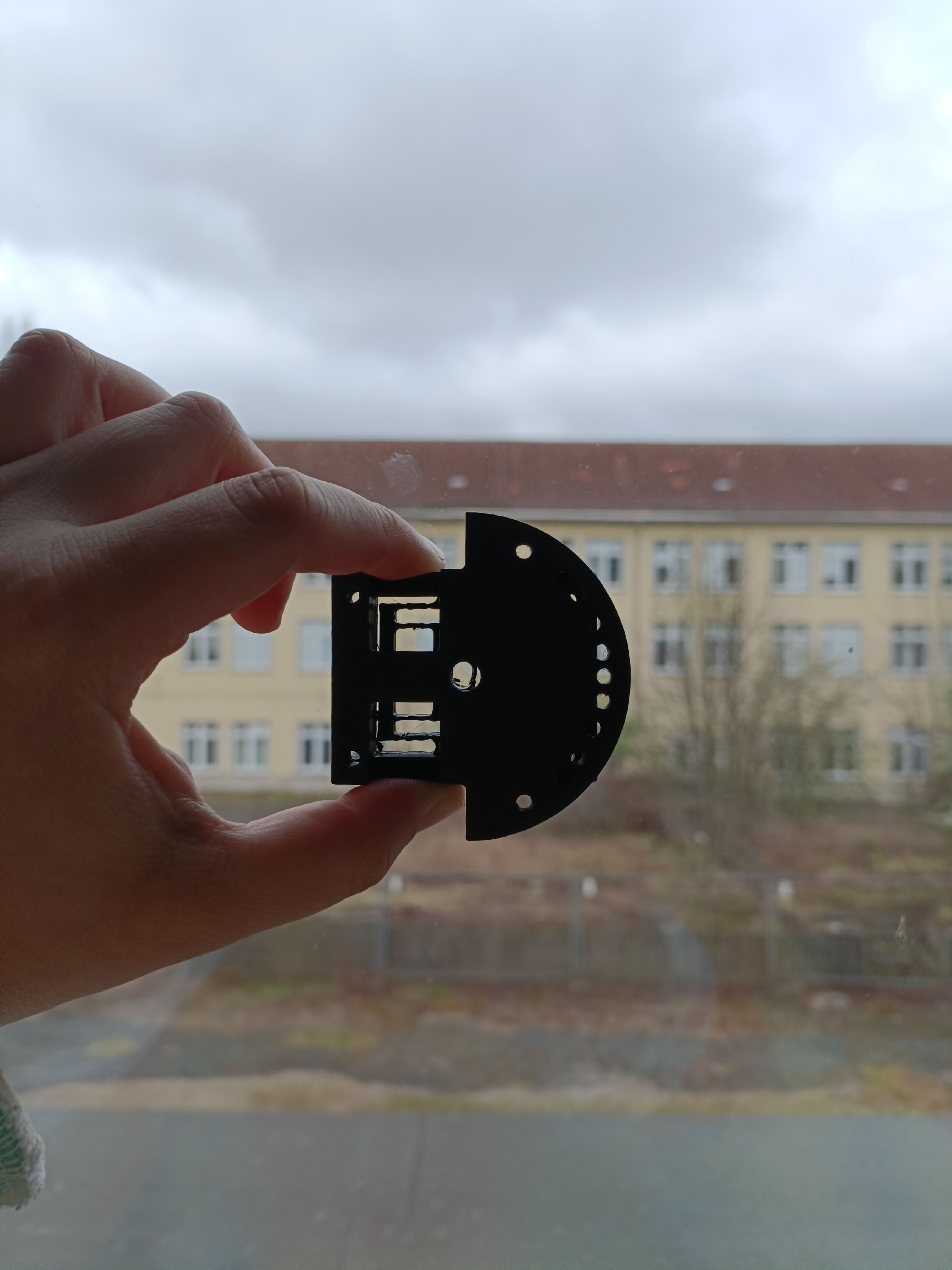
It features a modular interface plate now. These are the measurements 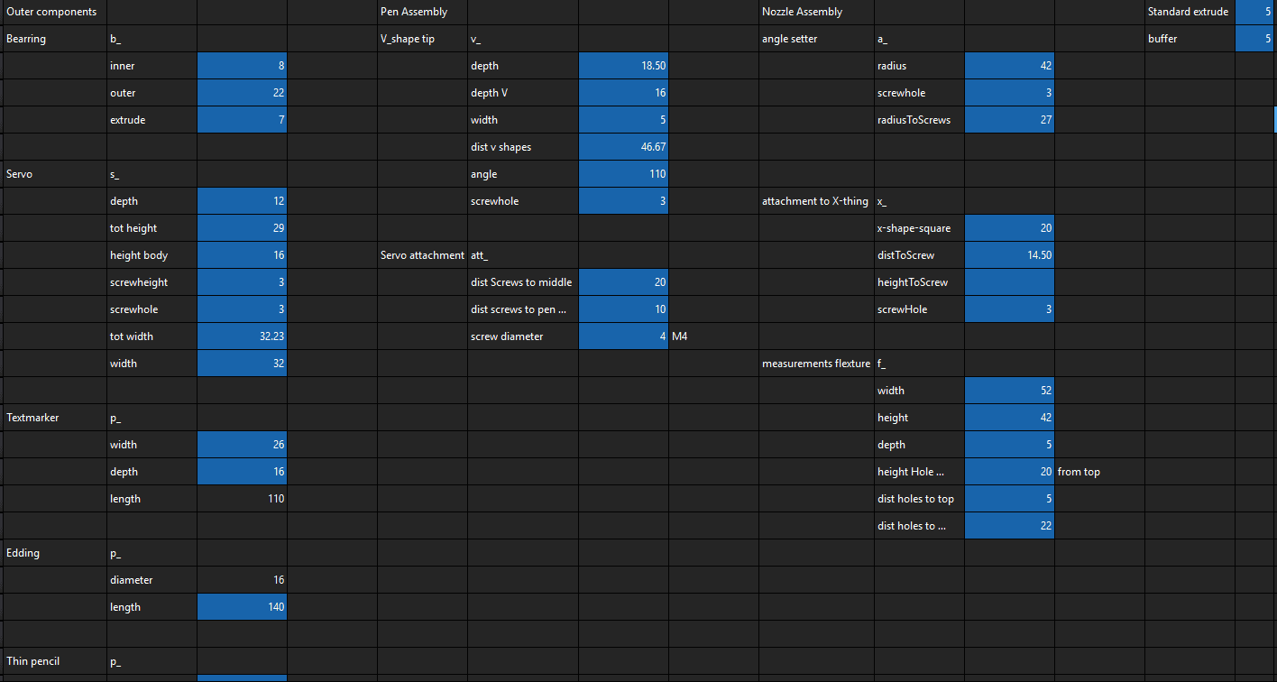
Spreadsheet in FreeCAD - Testing and fixing time!
Testing strength of the pen holder. That works (even tough it was intended to work with a rubber band) 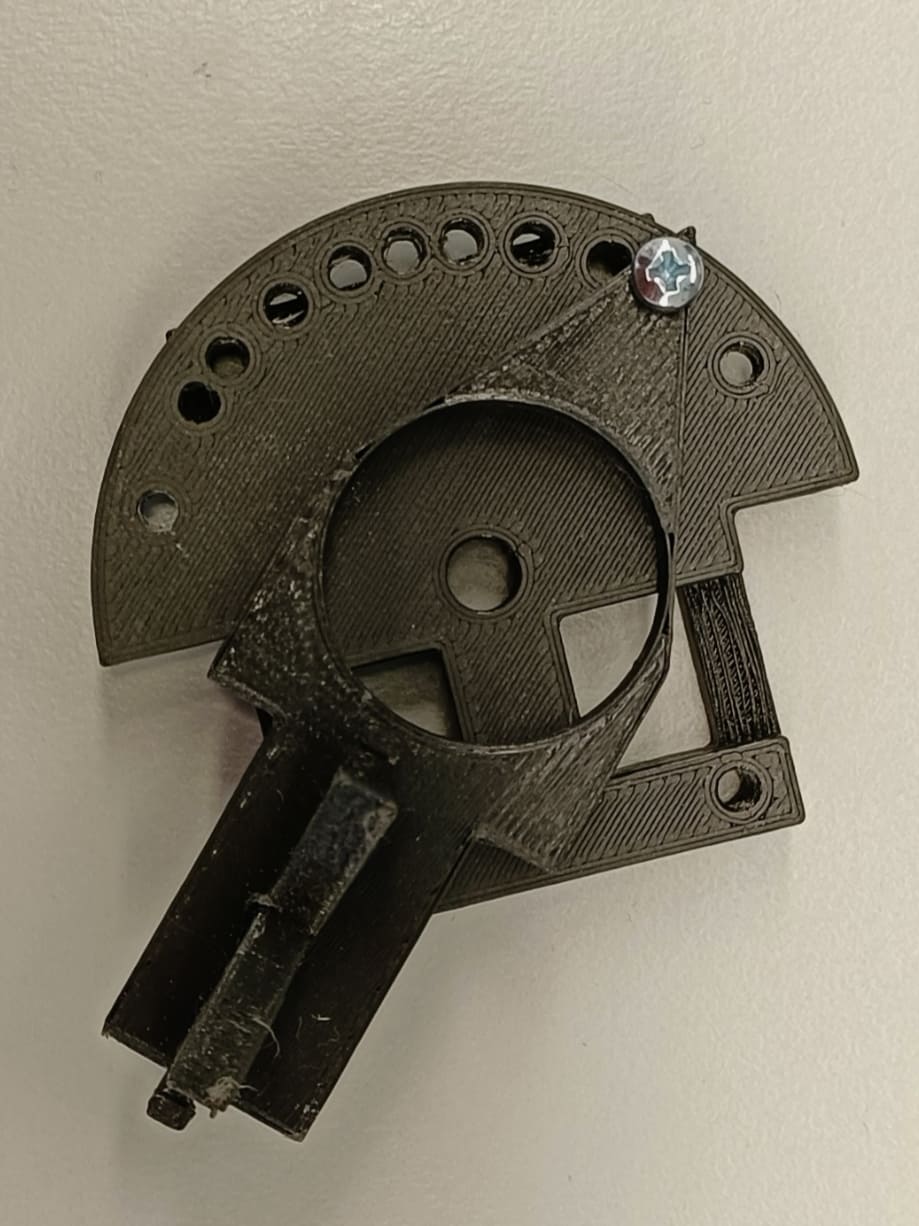
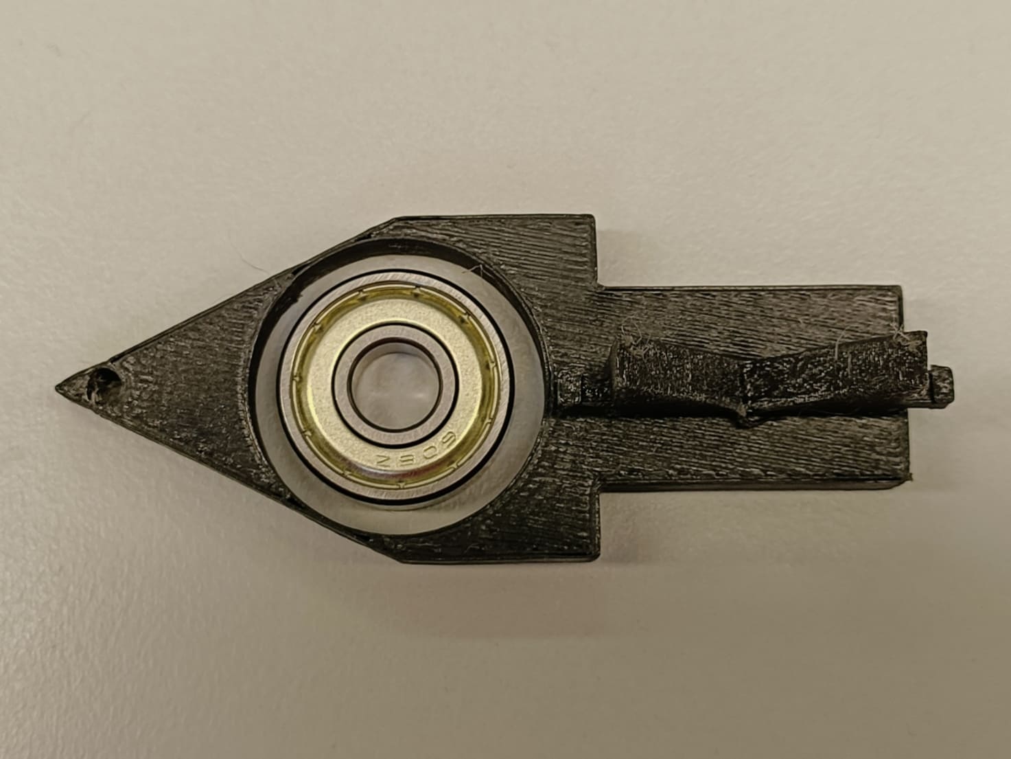
Left: angle testing mechanism works. Bearing hole is too big. Fixed issues. Right: Final result. Heated up the bearing hole for a tight, stable fit. Works. From top left to bottom right: Process of creating the flexture.
1: Mistakenly printed with PLA. Not flexturing.
2: Printed in PETG. A bit better but not flexturing enough. The holes do not align with the holder.
3: Printed a different flexture from the Pico V2 milling machine that Matthias found to have a comparison Flexturing very well. Too well. Flexturing also in an additional axis.
4: Another shot at my own flexture. This time it is bigger as my team mates asked. Not flexturing.
6: Redid the big flexture but made the lines to thin. It broke before I could test it.
7: Fixed the alignment issues of the smaller flexture. Final version because the time was up.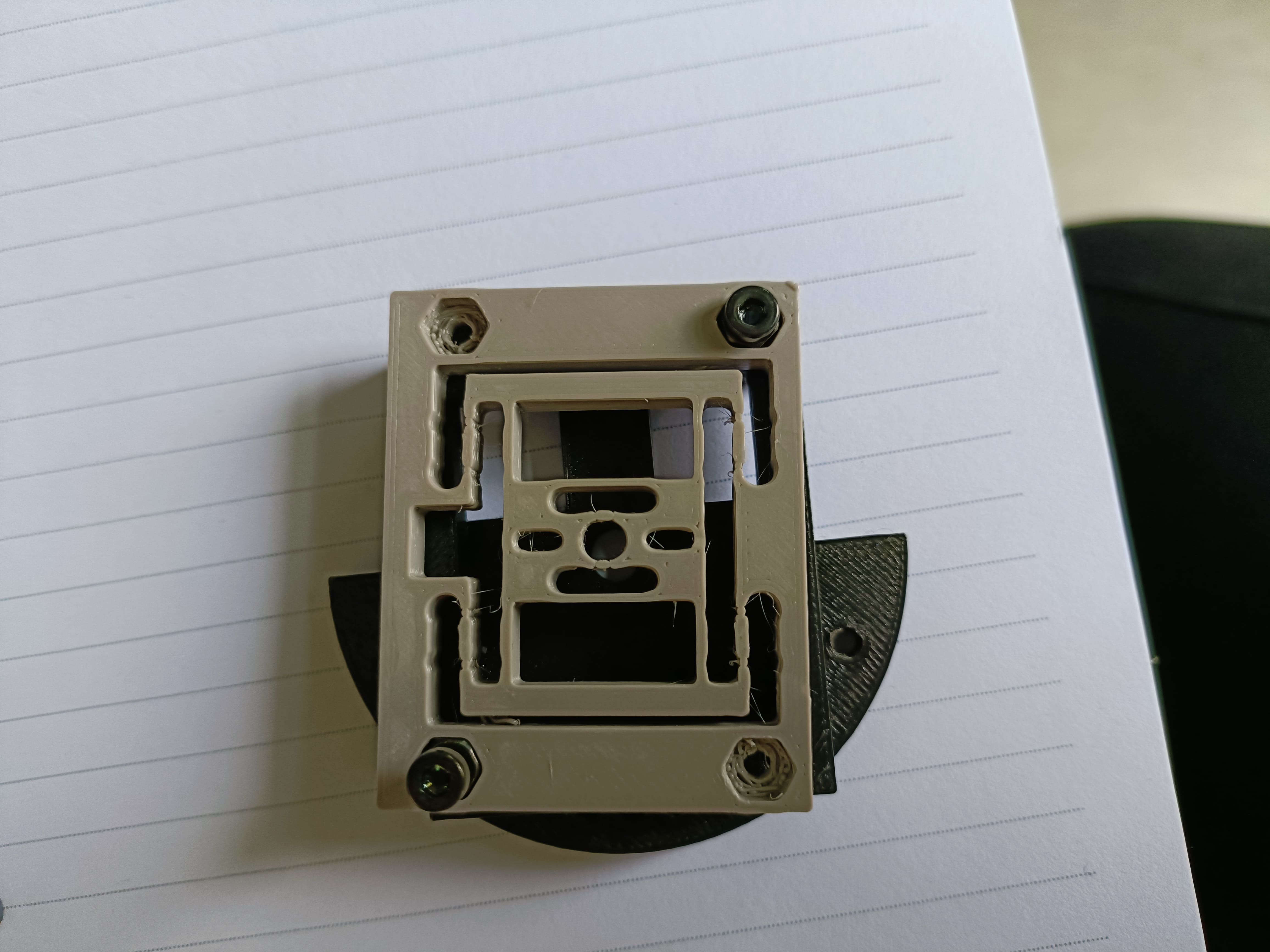
Fixed holes alignment issue. The main issue was that the export in FreeCAD did not feature the newest changes. Fixed it by selecting the last change I did instead of the body of the current project.