
Assignments
This week was molding and casting. After machine(such a hectic week), it was refreshing and nice to not have to work under pressure but then the final project knocks on my door
-knock knock,
who's there?
Final Project.
Final Project who?
Your Final Project!!
OHH NO, only 5 weeks were left so this week, I tried to dedicate as much as time as possible for my final project.
Table of Contents
- Group Assigment
- Review the safety data sheets for each of your molding and casting materials
- Make and compare test casts with each of them
- Compare printing vs milling mold
- Individual Assigment
- Design a mold around the process you'll be using, produce it with a smooth surface finish that does not show the production process, and use it to cast parts.
- Final Project Development
Group Assignment
For the group assignment, we reviewed the sadety data sheets for each of our molding and casting materials, and compared casts and prinitng vs milling mold. You can access the group assignment here
Individual Assignment
I started off by downloading an emoji with glasses on from the internet. Then I used SVG Converter-Online tool to convert the image to svg file.
- Go to the Website: Navigate to the SVG Converter website: SVG Converter-Online tool You will see a "Upload File" or "Choose File" button in the center
- Then you can click the "Choose File" or "Upload File" button. This opens a file browser where you can select the emoji image (e.g., a .jpg or .png file) from your computer. After selecting the image, click "Open."
- Download the SVG File: Once the conversion is complete, the website shows a "Download" button labeled "Download SVG". Click this button to save the new .svg file to your computer. The SVG file is now ready to be imported into Fusion 360.
How to Import an SVG in Fusion 360
- Open Fusion 360.
- Go to the Insert menu in the toolbar.
- Select Insert SVG.
- Choose the plane or face where you want to place the SVG.
- Click OK to finish the import.
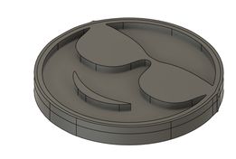
Then I imported that svg file into fusion and then extruded it. I extruded the SVG by 2.5 mm which is smaller than the endmill's diameter. This depth felt just right for the emoji design – deep enough to get a good, solid cast without making the mold overly thick or wasting material. Image source

Huge shout out to Mr. Yuichi TAMIYA as in his documentation we found the zip folder to download Modella Player 4. It was in this Google Drive. I downloaded both the Virtual Modella and Modella Player 4 because they will generate the toolpath for cutting my design and simulate it.
Modella Player 4 is a CAM (Computer-Aided Manufacturing) software that converts 3D designs into tool paths for milling machines.
Virtual Modella allows you to simulate the results of your 3D milling projects before actually cutting materials.
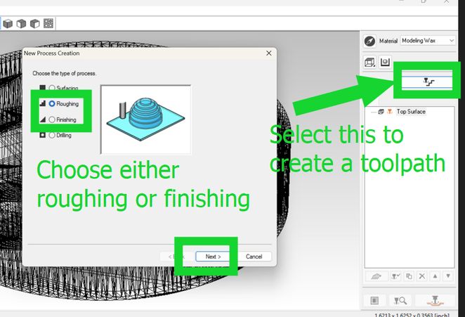
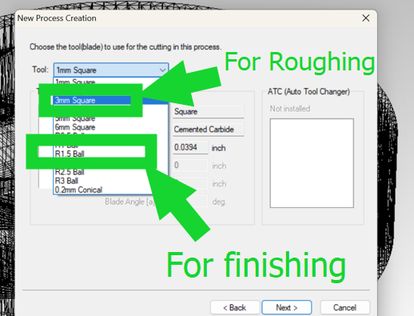
- Roughing: The first step where you quickly carve out the rough shape of your design. It’s all about removing big chunks of material to get the basics in place. Precision takes a back seat here, with speed and efficiency being the priority. Picture cutting in cubes or squares, using a 1/8-inch square end mill that makes quick work of the heavy lifting.
- Finishing: Once the rough shape is done, it’s time for the finishing touch. This stage is all refining the details, smoothing the surfaces, and ensuring the final dimensions are spot-on. Smaller and finer tools step in here to makes your design look professional.
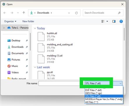
- Make sure your model is saved as a STL (.stl) file.
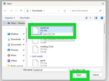
- Click [File] → [Open] and load your STL file.
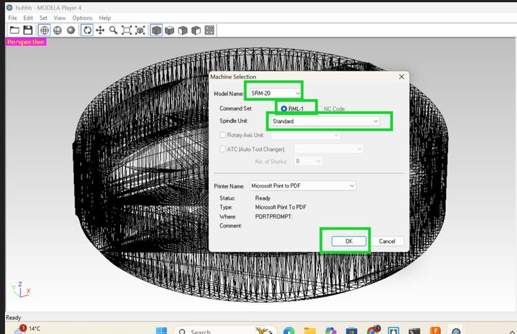
- Select the correct Modela machine you are using.( SRM-20 in my case). NOTE: If you don’t select the correct machine first, your toolpath settings might be wrong, and it could cause problems during cutting!
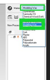
- Click [Material] → [Set Material] to ensure you have the correct material (like "Modeling Wax").
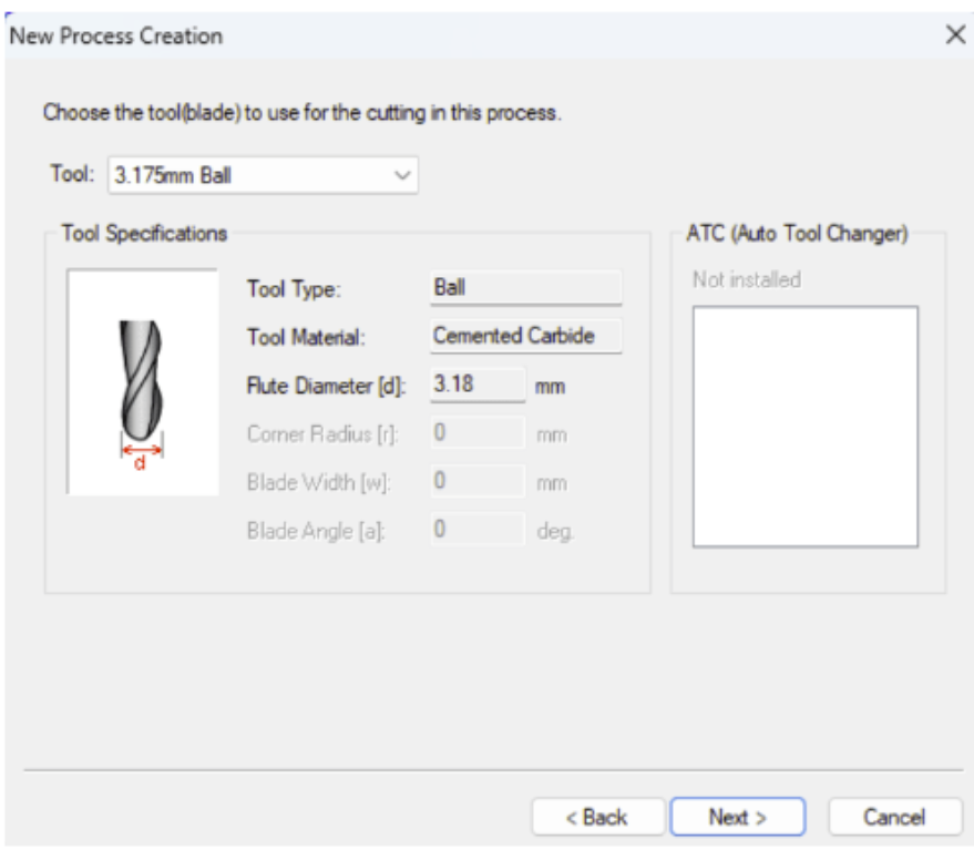
- Click [New Process] → [Roughing].
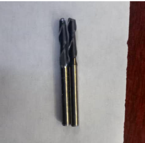
- Select a larger flat endmill( 1/8 inch or 3.175mm in my case). The tools diameter here is not 3 mm square as in the image down there but actually 3.175 mm
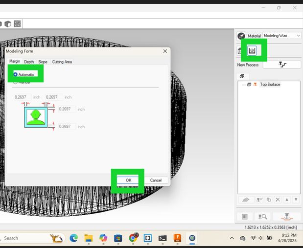
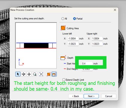
I defined the cutting boundary in the XY and Z directions around my design to create a milled 'box' that encloses my piece. In the setup, I specified the start height for both roughing and finishing to be 0.4 inches, as shown in the image below. This ensured that the toolpath began slightly above the material surface, providing a safe and clean entry for milling.
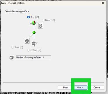
Then keep pressing next until you see "save your file as "
- When setting up the toolpath in Modela Player 4, I set it to 5 mm. The real purpose of the "Start Height" parameter is to define the height above the material surface where the milling machine's tool will begin its initial movement before it starts cutting into the material. It's essentially the clearance height for the tool's non-cutting movements. Setting it to 5 mm ensures that the tool moves safely above the workpiece when repositioning, preventing accidental scrapes or collisions before the actual milling process begins.
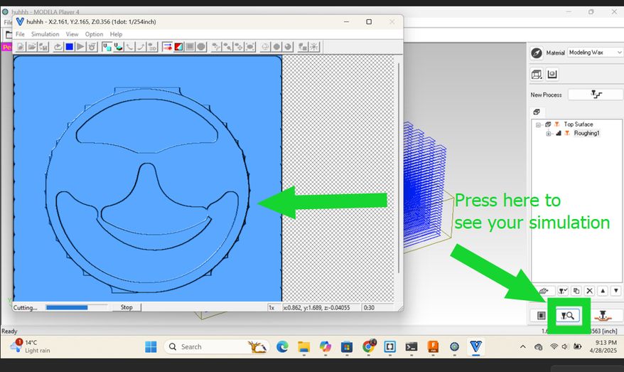
- Click [Preview] or [Simulate].
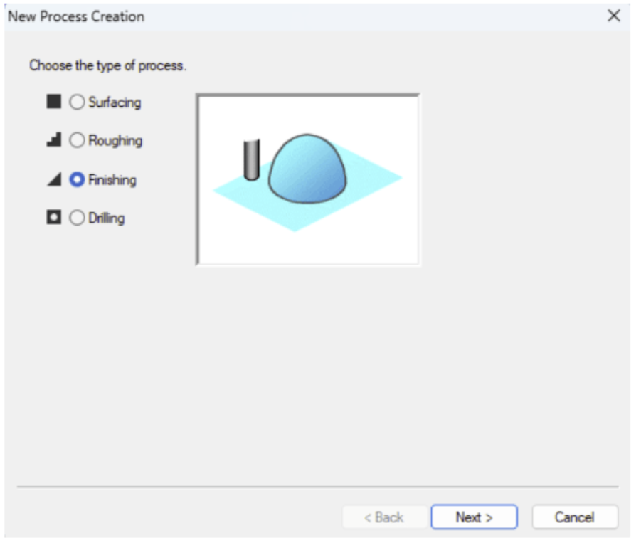
Now I am done with creating a toolpath for roughing but I have to do it for finishing too. So just repeat the process but instead of choosing roughing, choose finishing instead and choose R 0.15 ball.
Ooops! Error!!!
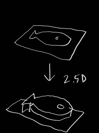
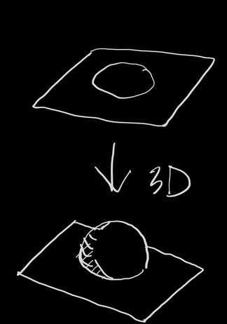
Late realization, our design was 2.5 D which is basically extruding directly from a 2d sketch which wouldn't meet the assignment requirements as it requires to produce a cast with a smooth surface. So instead of creating a completely new design i decided to add 2 spheres for my pupils. Thank you Rico san for this major disaster prevention(which is an exageration but still lots of time, energy and material would have gone to waste if he hadn't pointed it out.) These were the images he sent to clarify it to us:
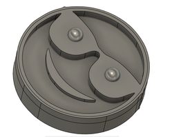
On my previous design only I added a sphere. Go to Create, select Sphere, choose a plane, set the center point, adjust the diameter, and confirm with OK
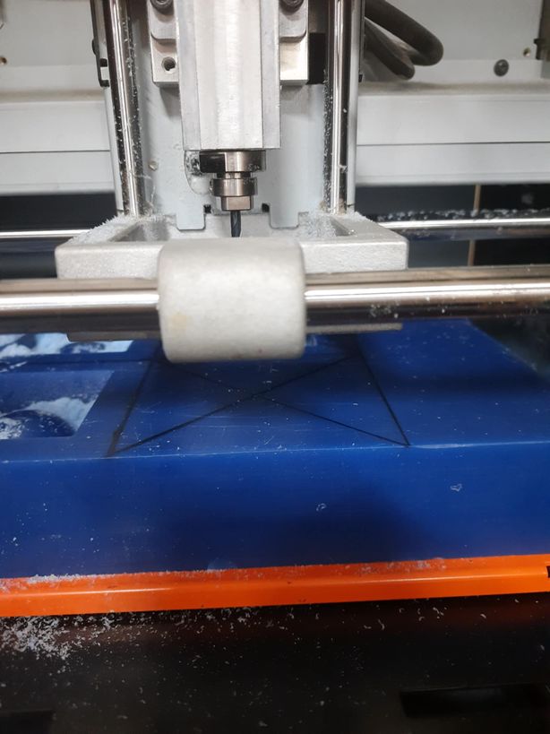
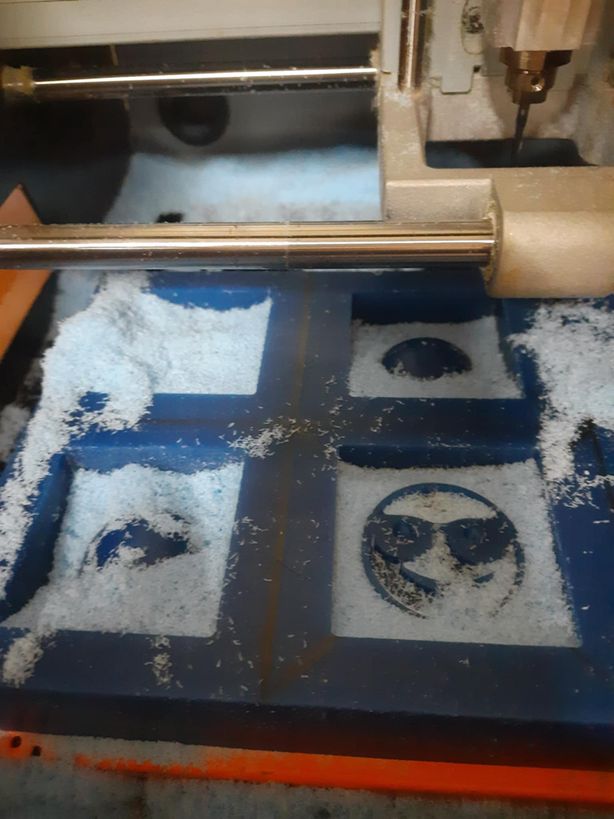
Before I started milling, I drew 2 diagonal lines across the wax to mark the center of the wax. This is because the origin point is in the center for the tool path created by modella player. After an awful long time, it was done and the amount of waste generated amazed me. I was wowed by it. Then I cleaned it!
Define travel speed = 20mm/sec (‘XY Speed’), feed = 10mm/sec (‘Z Speed’), spindle speed = 7000, & ‘Cutting-in Amount’= 1.2mm and step offset = 0.2mm (‘Path Interval’) here. I followed recommended settings used by sir Rico.
- Since we already had experience working with the SRM-20 machine, operating it for this task was relatively straightforward.
- The key difference in this process was the use of a different endmill specific to the task.
- The workflow closely resembled the PCB milling process, with particular attention given to setting the origin.
- For origin adjustment:
- X and Y origins were set to the center of the wax surface.
- Z origin was set to the surface level of the wax block.
- The reference point used for origin setting was aligned with the toolpath for both roughing and finishing operations.
- Roughing Process:
- A 3.175 mm square endmill was used.
- The roughing file was loaded into VPanel as output.
- The tool followed a contour path as defined in Modela Player.
- This step took approximately 2.5 hours to complete.
- The roughing created layered contours to prepare for surface smoothing in the finishing step.
- Finishing Process:
- The endmill was changed to a 1.5825 mm ball endmill.
- The Z origin was kept consistent, set from the wax surface edge.
- The finishing file was added to VPanel for execution.
- Using a similar milling workflow as PCB production, the process was completed successfully.
- The final output is shown in the image below (add image reference here).
The image of endmills is borrowed from Mr.Anith Ghalley
HEROSHOT
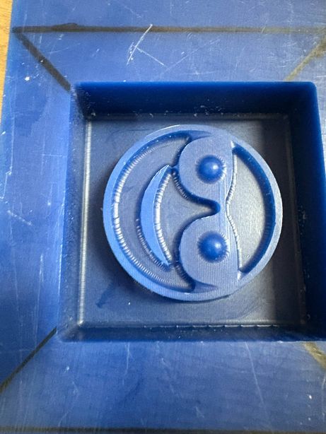
We used SILOCZEST Liquid Silicone Rubber (LSR 110) was used for molding and casting because it is easy to use and picks up fine details well. It is soft, flexible, and strong, which makes it easy to remove the mold without breaking it. It cures at room temperature and can be reused many times. LSR 110 works well with materials like resin, wax, and even food (if food-safe), making it a good choice for many different projects.
Image source
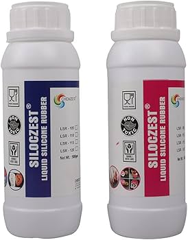
SILOCZEST LSR 110 comes in two parts — usually called Part A and Part B — because it's a two-component silicone. These parts must be mixed together to start the curing (hardening) process.
- Part A: Contains the base silicone.
- Part B: Contains the curing agent (catalyst).
- When mixed, a chemical reaction begins that turns the liquid into solid rubber.
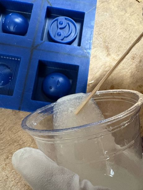
- Safety Measures: Before starting, we made sure to work in a well-ventilated area and wore gloves to avoid skin contact. We also had eye protection in case of splashes.
- Mixing Ratio: We used a 1:1 ratio by weight of Part A and Part B. It's crucial to get this right for the silicone to cure properly.
- Mixing: We thoroughly mixed Part A and Part B until the color was uniform, ensuring there were no streaks. This is important for even curing.
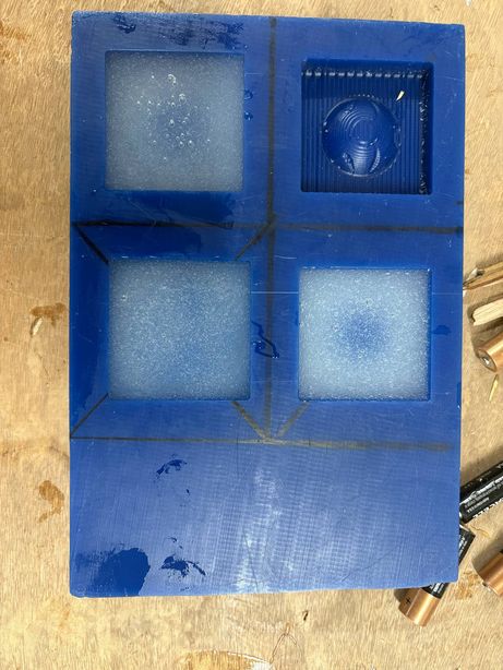
- Pouring: We carefully poured the mixture into our mold box, making sure to avoid trapping air bubbles.
- Curing Time: We waited for it to cure at room temperature. The curing time was approximately 24 hours, but we checked the manufacturer's instructions for the exact time.
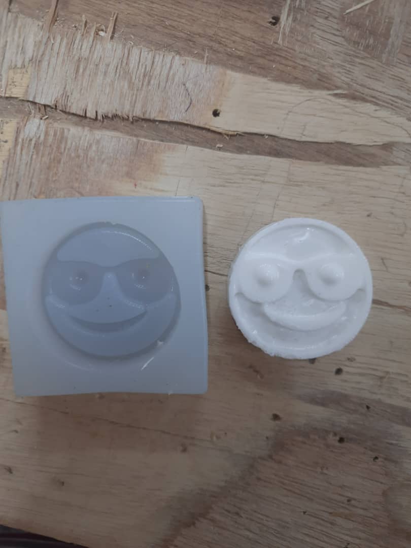
- Demolding: Once fully set, we carefully removed the mold. Because LSR 110 is flexible, this was easy without damaging the mold.
For the hard casting, I used Smooth-Cast™ 305. Here's how I handled it:
- The material is a two-part urethane resin, and it's designed to be virtually bubble-free, so I didn't need to do any vacuum degassing.
- For the mix ratio, I had two options: I could measure out **1A:1B by volume** or **100A:90B by weight**.
- Once I had my parts A and B ready, I mixed the solution for about **3 minutes**.
- I had to be careful during mixing because, from my experience, **the solution gets really hot** as it starts to cure.
- After mixing and pouring, the mixture cures in about **45 minutes**, which is quite fast and allows for quick turnaround on test casts.
- Bubble Removal: The primary method for minimizing air bubbles was through careful pouring.
Final Project Development
This week, I finalized the power supply for my project. The system will consist of an AC mains supply, stepped down and regulated to provide 9V for high-power components and 5V via a USB interface for the microcontroller. To achieve the required voltage levels, I will integrate two DC-DC buck converters for efficient step-down voltage regulation.
Rico san send me some videos to help me learn about power supply and learn and decide on it.
- How Buck, Boost & Buck-Boost DC-DC Converters Work
- The Most Versatile Voltage Converter you never heard of! The (S)EPIC Converter
- Power For Your Electronics Projects - Voltage Regulators and Converters
- Power ANY Arduino Project - The Ultimate Guide
- Everything You Need to Know about MOSFETs
Files
You can access the files here
Design