
Assignments
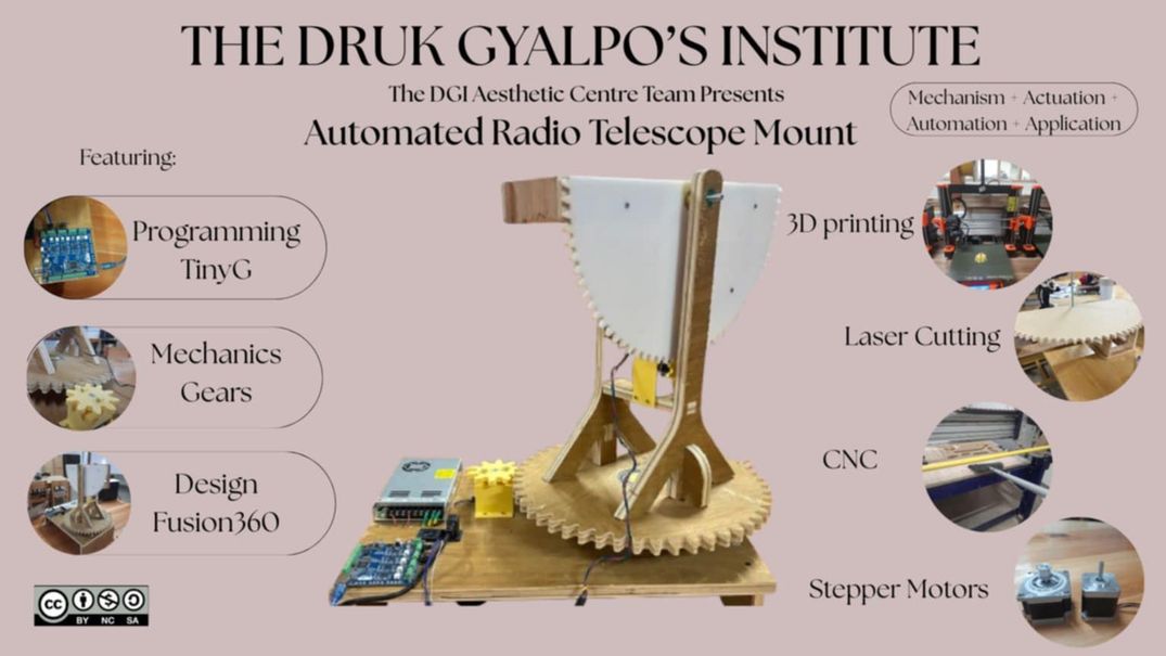
This week was more of a demo/trailer of our final project except that we will be working in solo ways for our final project. The machine that we had decided on was an automated radio telescope mount that can rotate horizontally as well as vertically(about 110 degrees).
Table of Contents
- Group Assigment
- Design a machine that includes mechanism + actuation + automation + application
- Build the mechanical parts and operate it manually Document the group project
- Individual Assigment
- Document your individual contribution
- Final Project Development
Group Assignment
For the group assignment, we brainstormed several ideas but in the end we decided to make a mount for the radio telescope that we have at our school to automate it. We divided the tasks among ourselves and I was mainly responsible for mechanical design which is a very essential part of the machine as the key to automation will be proper gear meshings. Apart from that I was mainly involved in the fabrication of our mount and cradle with the CNC. I also designed the roller support stand and 3d printed it. You can access the group assignment here
Individual Assignment
Finally the machine design week has come and its kinda intimidating as it not only seems but is hectic. It was like creating our final project in a group. After endless discussions about our idea, we decided to divide the parts and I came to be in-charge of the mechanical design basically learning about gear ratios and teeths and much more. So lets start by fishing out some notes from my notes.
You can generate gears online using this online tool.. It is very helpful.
You can learn more about it here
Gear Ratio
A gear ratio is the ratio between the number of teeth on two meshing gears or the ratio of their rotational speeds. It indicates how many times the driving gear must rotate to make the driven gear complete one full rotation.
In our design, the gear on the side originally had a gear ratio of 1:12.5 in a full circle, but we had to divide the circle in half to meet the design requirements. The base gears had a gear ratio of 1:14.
Formula
Gear Ratio = Number of teeth on driven gear / Number of teeth on driving gear
Example
If the driving gear has 10 teeth and the driven gear has 20 teeth:
Gear Ratio = 20 / 10 = 2:1
This means the driving gear must rotate 2 times for the driven gear to rotate once.
Module in Gears
The module is the fundamental unit of tooth size in the metric system. Gears with the same module will have teeth of compatible sizes and shapes, ensuring proper meshing. If you were to use gears with different modules, their teeth wouldn't align correctly, leading to jamming, excessive wear, and ultimately, failure of the system.
Module (m) = Pitch Circle Diameter (D) / Number of Teeth (T)
Image source
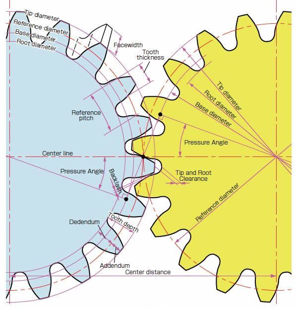
Pressure Angle (20°)
It's the angle at which gear teeth push on each other.
20° is the standard angle.
Why it matters:
- Affects how smooth and strong the gear works.
- 20° gives strong teeth and works well in most gear setups.
Clearance (0.05 mm)
It's the tiny gap between the top of one gear tooth and the bottom of the other.
Why it matters:
- Prevents the teeth from jamming or rubbing too hard.
- Helps the gears move smoothly, even if they're not perfect.
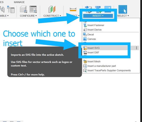
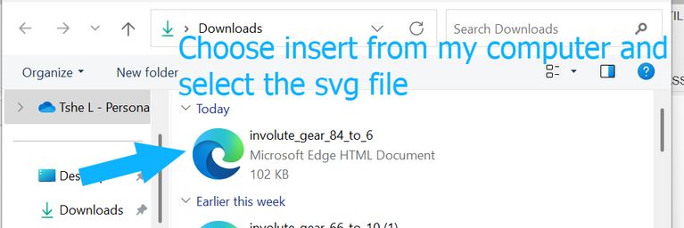
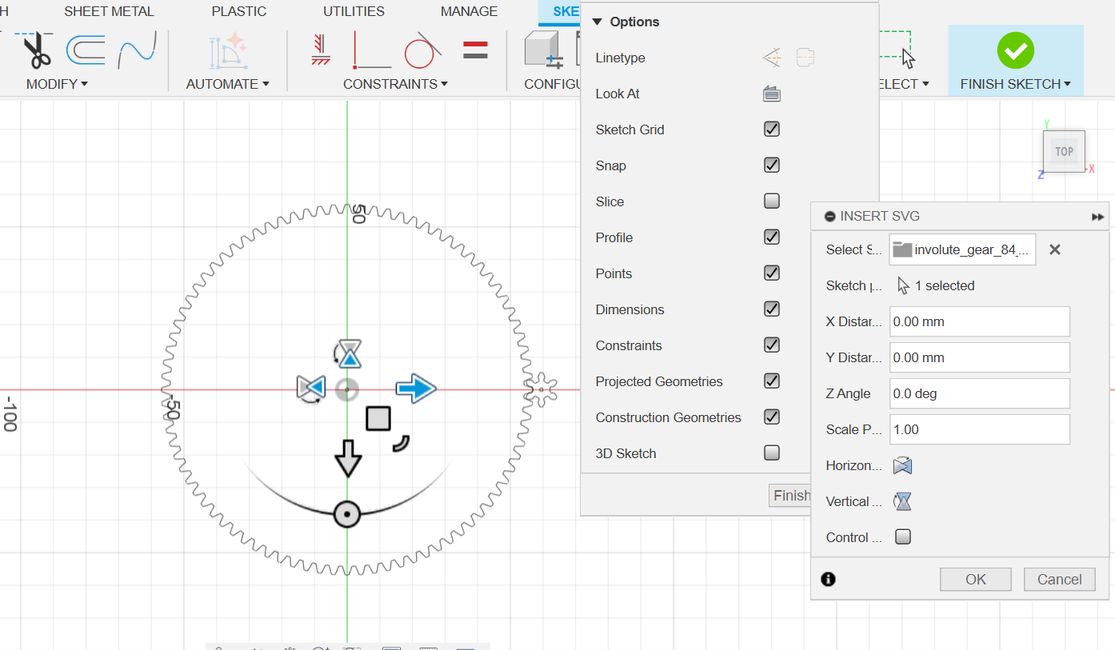
As mentioned before, I used an online gear generator and inserted these requirements which gave us an image of how those gears will look which can be downloaded with either in dxf or svg format.
The small gear for the base and the small gear for the side are not the same size.
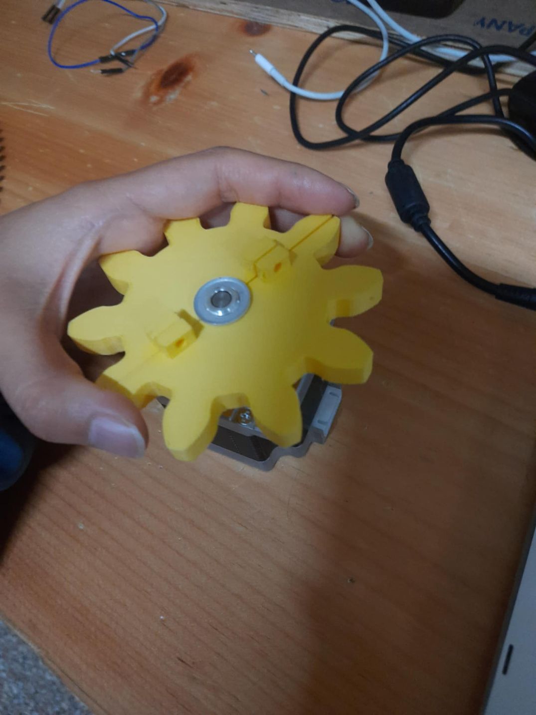
The small gear for the base has 8 teeth and a pitch circle diameter of 32 mm.
The small gear for the side has 6 teeth and a pitch circle diameter of 30 mm
Parameter	Value for the Base gears that has a big gear of 40 cm diamter and 8 cm diamter small gear.
Gear 1 Tooth Count (n1):	100 (external gear)
Gear 2 Tooth Count (n2):	8
Module (mm):	4
Pressure Angle (degrees):	20
Clearance (mm):	0.05
Gear 1 Center Hole Diameter (mm):	4
Gear 2 Center Hole Diameter (mm):	4
Gear Center Distance (mm):	225.000
Gear 1 Pitch Circle Diameter (mm):	400
Gear 1 Outer Circle Diameter (mm):	32
Gear 2 Pitch Circle Diameter (mm);	408
Gear 2 Outer Circle Diameter (mm):	40.000
Show Crosshairs:	No
Show Reference Geometry:	No
Show Gears;	Yes
Parameter	Value for the side gear that has a radius of 21 cm(which will be a semi circle) and then the small gear will have a diameter of 3 cm.
Gear 1 Tooth Count (n1):	84 (external gear)
Gear 2 Tooth Count (n2):	6
Module (mm):	5
Pressure Angle (degrees):	20
Clearance (mm):	0.05
Gear 1 Center Hole Diameter (mm):	4
Gear 2 Center Hole Diameter (mm):	4
Gear Center Distance (mm):	225.000
Gear 1 Pitch Circle Diameter (mm):	420.000
Gear 1 Outer Circle Diameter (mm):	430.000
Gear 2 Pitch Circle Diameter (mm);	30.000
Gear 2 Outer Circle Diameter (mm):	40.000
Show Crosshairs:	No
Show Reference Geometry:	No
Show Gears;	Yes
| Gear Type | Tooth Count (N) | Module (m) | Pitch Circle Diameter (D) | Outer Circle Diameter | Pressure Angle | Clearance |
|---|---|---|---|---|---|---|
| Base Big Gear | 100 | 4 | 400 mm | 408 mm | 20° | 0.05 mm |
| Base Small Gear | 8 | 4 | 32 mm | 40 mm | 20° | 0.05 mm |
| Side Big Gear | 84 | 5 | 420 mm | 430 mm | 20° | 0.05 mm |
| Side Small Gear | 6 | 5 | 30 mm | 40 mm | 20° | 0.05 mm |
One of the primary uses of gears is to change the rotational speed and, consequently, the torque. A gear ratio greater than 1 (driven gear has more teeth than the driving gear, like your base gears with a ratio of 100:8 or approximately 12.5:1) results in a reduction in speed of the driven gear but an increase in its torque. This is essential when you need precise, slow movements with significant power, which is likely the case for accurately pointing a radio telescope.
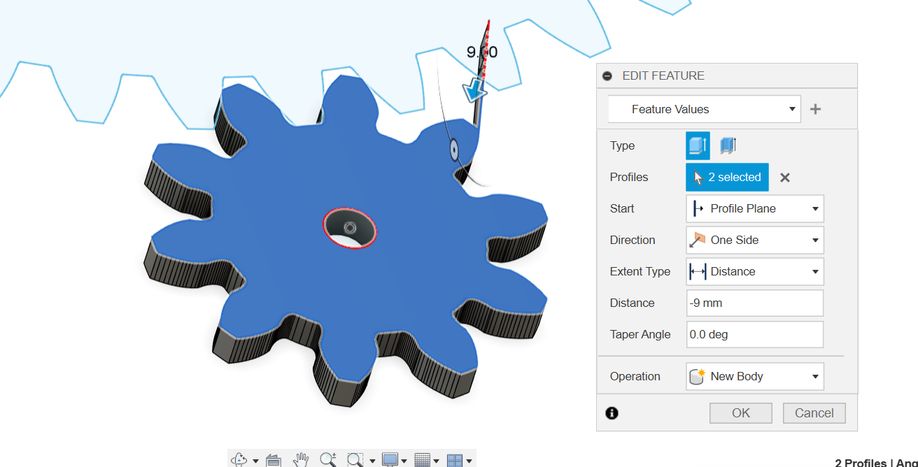
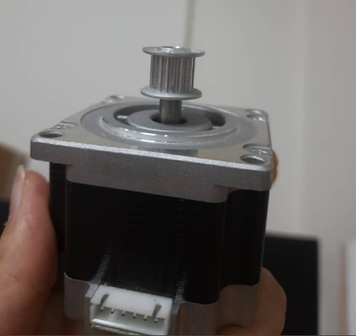
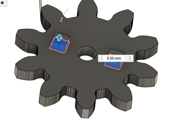
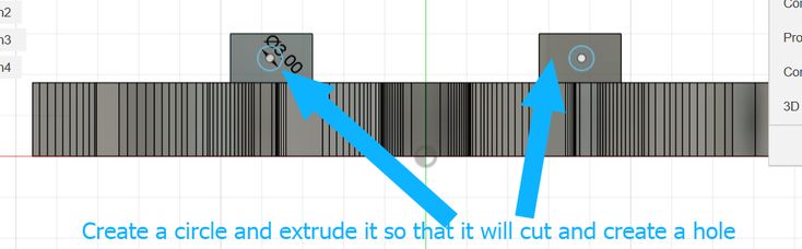
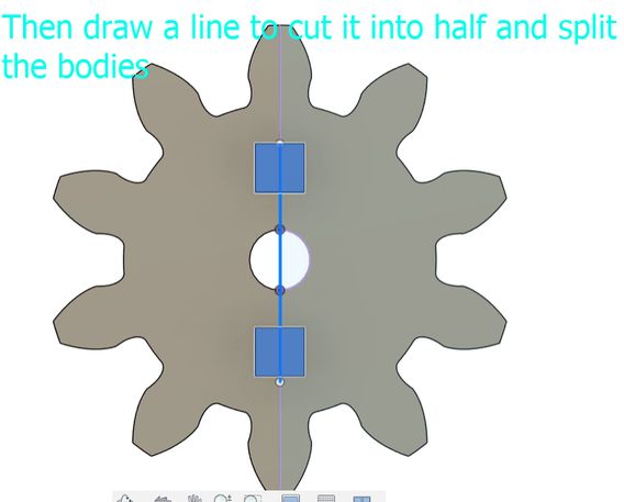
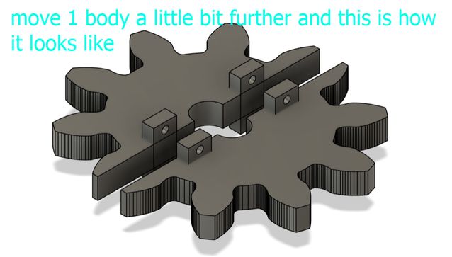
I coldnt directly 3d print that gear because our stepper motor had a head so, which prevented a single, solid 3D-printed gear from being directly mounted. So i tweaked the design a little where I split it into 2 parts and it comes together and gets connected via screwholes.

Definition
Module (m) = Pitch Diameter (D) / Number of Teeth (N)
Pitch Diameter (D): The diameter of the pitch circle (where teeth effectively engage).
Number of Teeth (N): Self-explanatory.
Units
Measured in millimeters (mm).
All gears that mesh must have the same module.
I used an online tool Online Gear Generator which will be pretty confusing if you are not clear with the concept of teeths and modules and pitch diameter.
Then I tested out the different gears. I also had some time to kill, so I helped Kezang to fabricate the design of our machine.
3D prinitng
Measured in millimeters (mm).
3D Printing the small gears for the Base and Side Gears
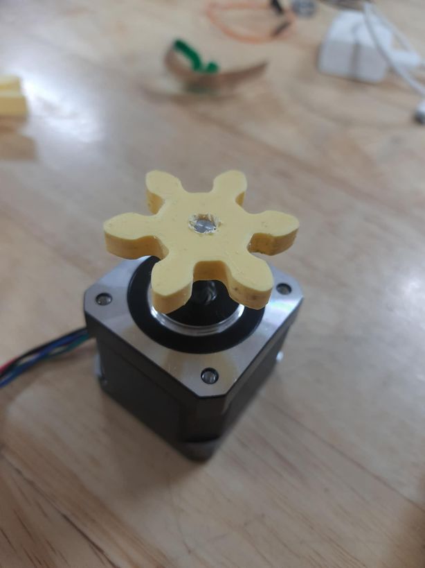
Once the small gear was finalized, I sliced the STL file using PrusaSlicer and printed it using PLA filament on the Prusa i3 MK3S 3D printer. The infill was set to 15%. After printing, I cleaned the support structures and tested its fit on the motor shaft. The results were accurate, and the teeth meshed well with the larger gear during testing.
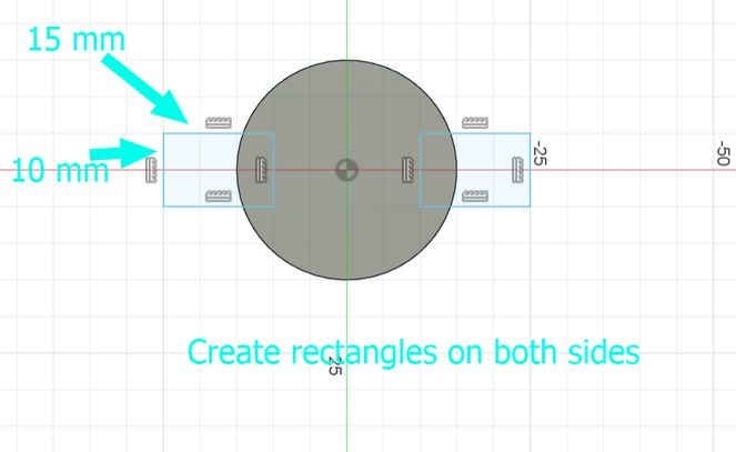
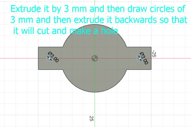
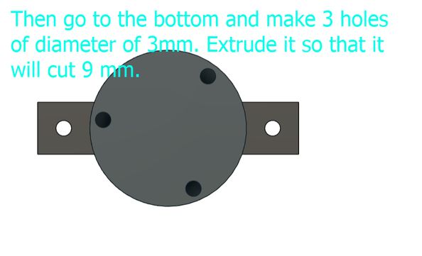
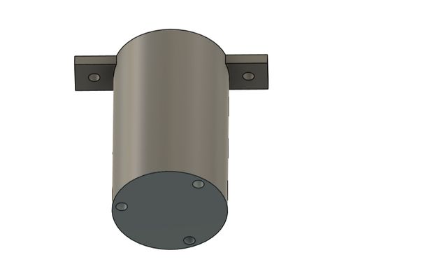
Then I designed and printed the supports for the roller at the base of the radio mount for smooth rotation.
CNCing the Big Gears
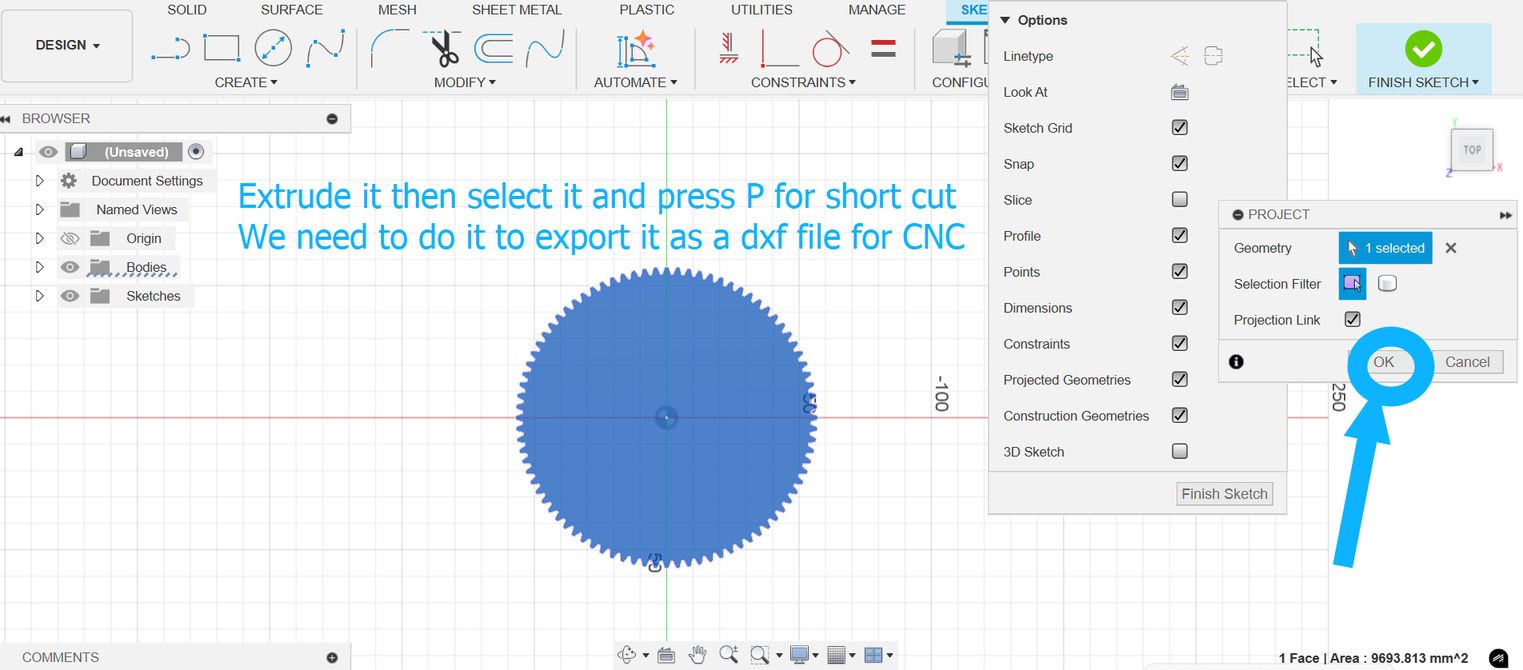
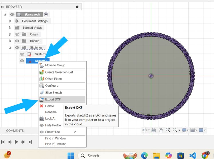
For the large gears, I used CNC machining. After exporting the DXF file from Fusion 360, I imported it into VCarve Pro to generate toolpaths. The material used was 12mm MDF wood, and I used a 3mm flat-end mill bit. After setting the correct feeds and speeds, I ran the job on the CNC ShopBot. Once the cutting was done, I sanded the edges slightly and tested the gear. It fit perfectly with the 3D printed small gear and rotated smoothly without any skipping or backlash.
Fabricating and Assembling the Radio Telescope Mount
Besides the mechanical design and gear system, I was also actively involved in fabricating and assembling the radio telescope's mount and upper structure. This part involved working with both wood and metal components, aligning the azimuth and elevation mechanisms, and ensuring structural stability for the dish support.
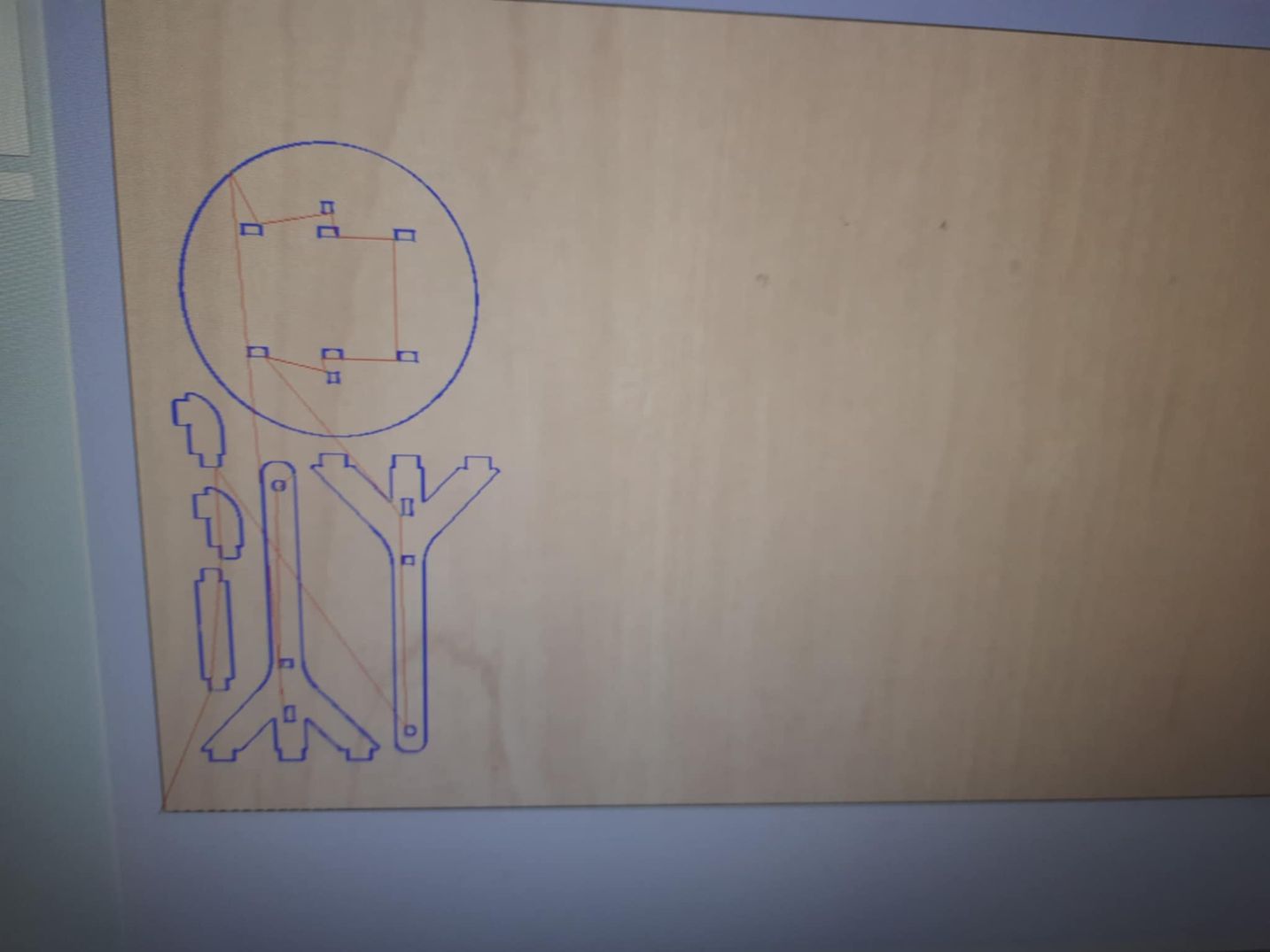
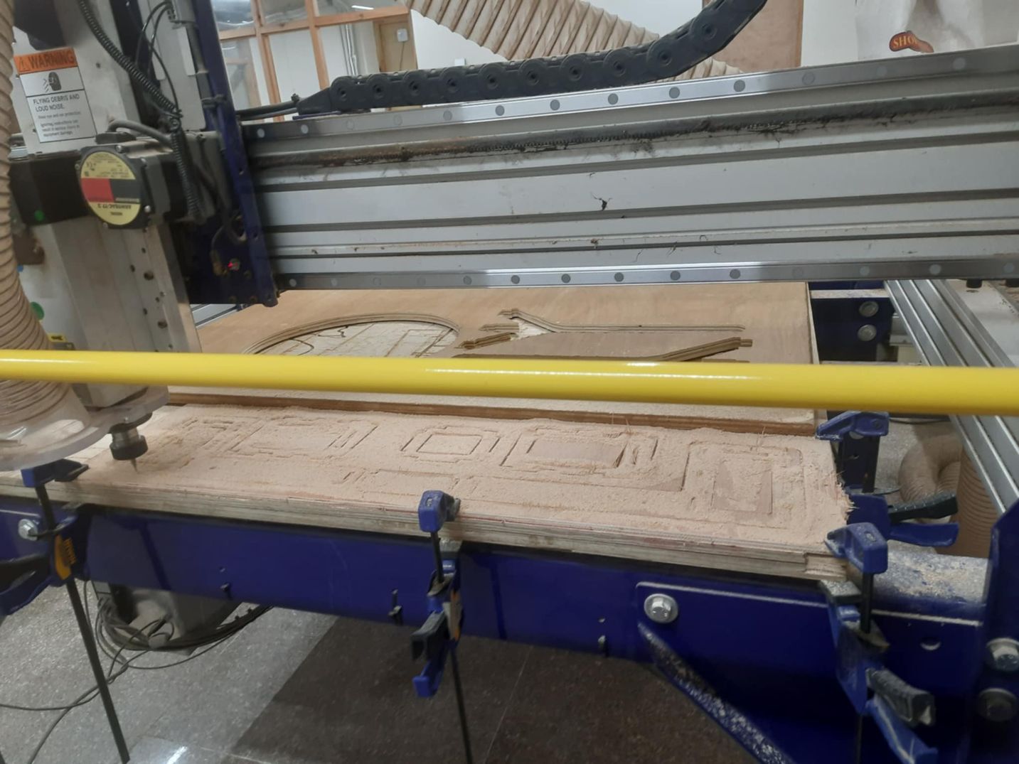
I helped cut the parts for the mount and the cradle and the big 40 cm gear using CNC. Preparing the DXF file in VCarve Pro involved several steps that we did in Computer Controlled Machining Week First, I imported the DXF file that I had exported from the online gear generator. Then, I had to define the toolpath. Since we were using a 6mm flat-end mill on 18mm wood, I selected a profile toolpath. I also added 3 tabs in each vector – small bridges of material left uncut – to ensure the gear remained fixed during the machining process and didn't get thrown around by the router.
Operating the CNC ShopBot was a hands-on experience. After securing the wood to the bed with clamps, I carefully zeroed the machine to set the starting point for the cut. Then, I loaded the toolpath file and started the job. It was noisy as usual but I had the headphones and glasses(basically the safety gears required) The entire process required constant attention to ensure everything was running smoothly and safely.
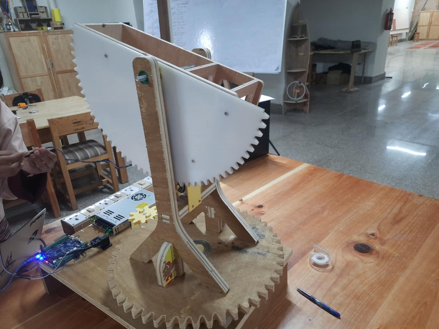
Once all the parts were ready, we began assembling the base structure, making sure everything went well and to check if anything requires redesigning. We used a bearing in the middle of the big 40 cm gear for smooth rotation . The final result was a stable which made us very proud and happy.
Difference between the Initial Plan VS Final Output
We changed our designs multiple times as we had to go through with the design again and again. In the end, where we initially planned on using 2 stepper motors to facilitate movement with the cradle, we decided that 1 gear was more than enough so we ended up using only 1 stepper motor at the side. We had also thought of creating a huge hole in the side gear to reduce weight but we learned that the motor could handle acrylics weight.
Moreover, we planned to extend the CNC cut woods at the side and create a motor enclosure (using 3d printing) but then opted for a better and easier alternative which was to create an enclosure and place it on the support stand that held the 2 stands.
We also thought to use roller stands to support the base but then in the end it was unnecessary as our base was strong enough with the bearing
Reflection
This week was enormous fun as I got to learn a lot about so many new things. Till now I had only seen gears in mechanical shops or factories in movies but now I actually learned about their working mechanism which was baffling to be honest. It was also eye opening to see how much though process and dsigning went into making our design as the more we designed, the more problems we faced. It helped me gain critical thinking and problem solving skills. We also had to collaborate and discuss about it for an awful lot of time, so a lot of cooperation was exchanged. I hope the machine that we created will be utilized for a much greater purpose and we plan to scale the size up in the future!!
Files
You can access the files here
Gear for Radio Mount base
f3d files and dxf files
Support for roller at the base of radio mount