Mechanical Design, Machine Design
Part 1: Mechanical Design
- Design a machine that includes mechanism + actuation + automation + application
- Build the mechanical parts and operate it manually
- Document the group project
Part 2: Machine Design
- Actuate and automate your machine
- Document the group project
IT'S MACHINE WEEK!!!
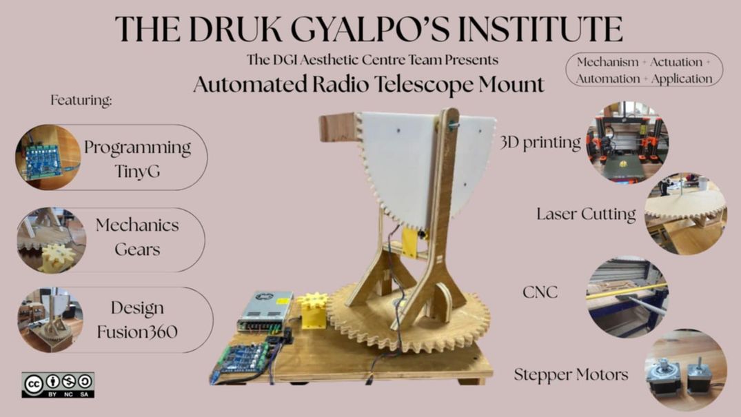
For this week's group assignment, we decided that we will work together on building an automated radio telescope mount.
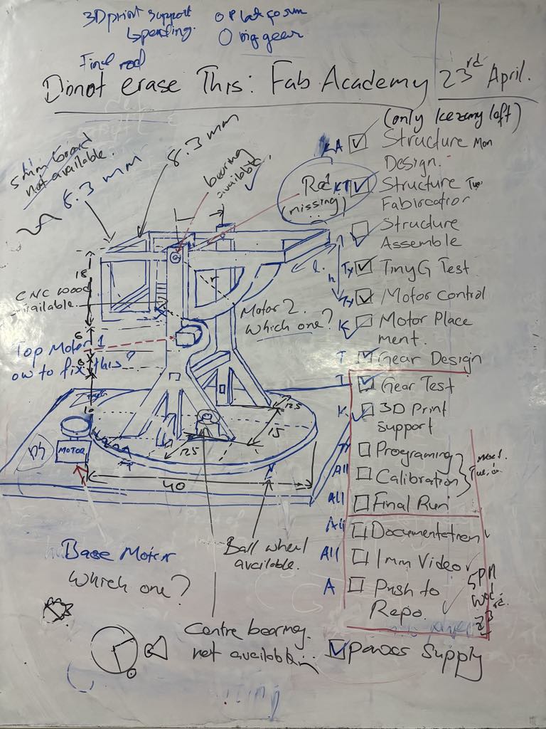
Design plan and idea
To get started, we sketched our design plan and divided our individual tasks within the three of us. Tsheltrim will be incharge of the mechanical design, Kezang will takeover the designing part and Tsheyang will take over the programming part. We all will fabricate, assemble and test it together. You can find out more about our individual contribution by visiting our personal documentation page.
The idea for our project stemed from a project that was already being done in our school - a radio telescopope, which had to be manually positioned in the sky in order to recieve the radio signals. In order to complete this assignment and also contribute to this project, we decided to make an automated one. We will design and develop a mount consisting of 2 main motion - the base rotation and the elevation.
Design and Fabrication
Mechanical Design
You can generate gears online using this online tool.. It is very helpful.
Gear Ratio
A gear ratio is the ratio between the number of teeth on two meshing gears or the ratio of their rotational speeds. It indicates how many times the driving gear must rotate to make the driven gear complete one full rotation.
Gear Ratio = Number of teeth on driven gear / Number of teeth on driving gear
Module in Gears
The module is the fundamental unit of tooth size in the metric system. Gears with the same module will have teeth of compatible sizes and shapes, ensuring proper meshing. If you were to use gears with different modules, their teeth wouldn't align correctly, leading to jamming, excessive wear, and ultimately, failure of the system.
Module (m) = Pitch Circle Diameter (D) / Number of Teeth (T).
Image source
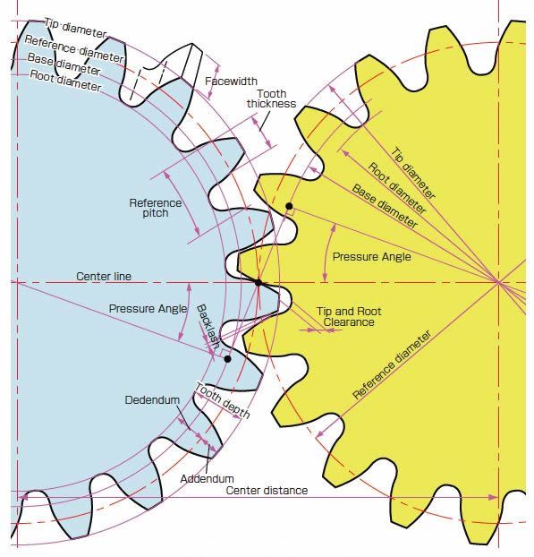
Pressure Angle (20°)
It's the angle at which gear teeth push on each other.
20° is the standard angle.
Why it matters:
- Affects how smooth and strong the gear works.
- 20° gives strong teeth and works well in most gear setups.
Clearance (0.05 mm)
It's the tiny gap between the top of one gear tooth and the bottom of the other.
Why it matters:
- Prevents the teeth from jamming or rubbing too hard.
- Helps the gears move smoothly, even if they're not perfect.
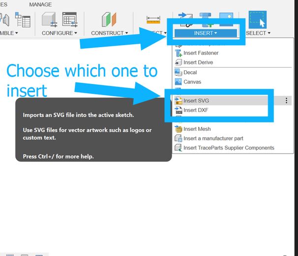
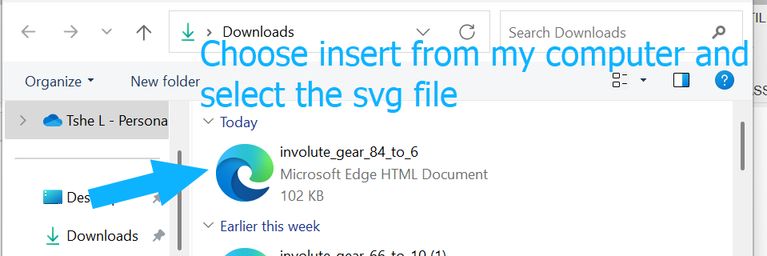
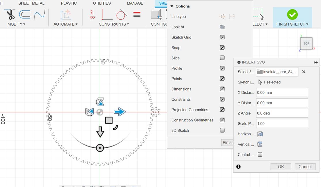
As mentioned before, I used an online gear generator and inserted these requirements which gave us an image of how those gears will look which can be downloaded with either in dxf or svg format.
The small gear for the base and the small gear for the side are not the same size.
The small gear for the base has 8 teeth and a pitch circle diameter of 32 mm.
The small gear for the side has 6 teeth and a pitch circle diameter of 30 mm
Parameter	Value for the Base gears that has a big gear of 40 cm diamter and 8 cm diamter small gear.
Gear 1 Tooth Count (n1):	100 (external gear)
Gear 2 Tooth Count (n2):	8
Module (mm):	4
Pressure Angle (degrees):	20
Clearance (mm):	0.05
Gear 1 Center Hole Diameter (mm):	4
Gear 2 Center Hole Diameter (mm):	4
Gear Center Distance (mm):	225.000
Gear 1 Pitch Circle Diameter (mm):	400
Gear 1 Outer Circle Diameter (mm):	32
Gear 2 Pitch Circle Diameter (mm);	408
Gear 2 Outer Circle Diameter (mm):	40.000
Show Crosshairs:	No
Show Reference Geometry:	No
Show Gears;	Yes
Parameter	Value for the side gear that has a radius of 21 cm(which will be a semi circle) and then the small gear will have a diameter of 3 cm.
Gear 1 Tooth Count (n1):	84 (external gear)
Gear 2 Tooth Count (n2):	6
Module (mm):	5
Pressure Angle (degrees):	20
Clearance (mm):	0.05
Gear 1 Center Hole Diameter (mm):	4
Gear 2 Center Hole Diameter (mm):	4
Gear Center Distance (mm):	225.000
Gear 1 Pitch Circle Diameter (mm):	420.000
Gear 1 Outer Circle Diameter (mm):	430.000
Gear 2 Pitch Circle Diameter (mm);	30.000
Gear 2 Outer Circle Diameter (mm):	40.000
Show Crosshairs:	No
Show Reference Geometry:	No
Show Gears;	Yes
| Gear Type | Tooth Count (N) | Module (m) | Pitch Circle Diameter (D) | Outer Circle Diameter | Pressure Angle | Clearance |
|---|---|---|---|---|---|---|
| Base Big Gear | 100 | 4 | 400 mm | 408 mm | 20° | 0.05 mm |
| Base Small Gear | 8 | 4 | 32 mm | 40 mm | 20° | 0.05 mm |
| Side Big Gear | 84 | 5 | 420 mm | 430 mm | 20° | 0.05 mm |
| Side Small Gear | 6 | 5 | 30 mm | 40 mm | 20° | 0.05 mm |
One of the primary uses of gears is to change the rotational speed and, consequently, the torque. A gear ratio greater than 1 (driven gear has more teeth than the driving gear, like your base gears with a ratio of 100:8 or approximately 12.5:1) results in a reduction in speed of the driven gear but an increase in its torque. This is essential when you need precise, slow movements with significant power, which is likely the case for accurately pointing a radio telescope.
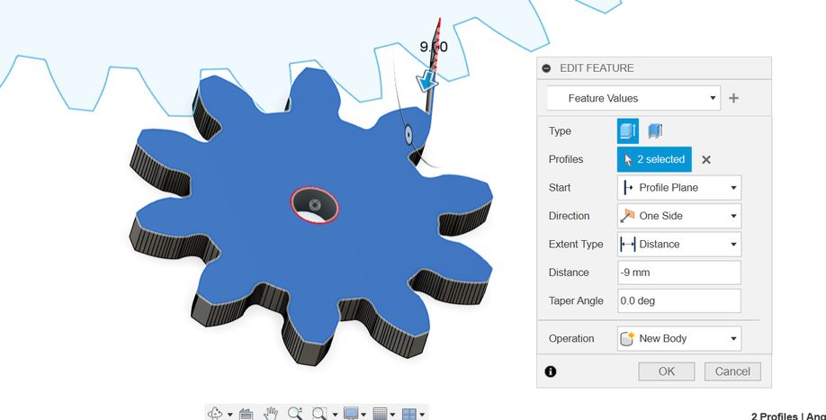
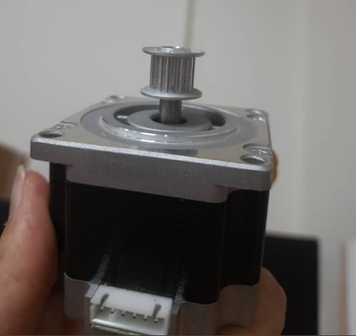
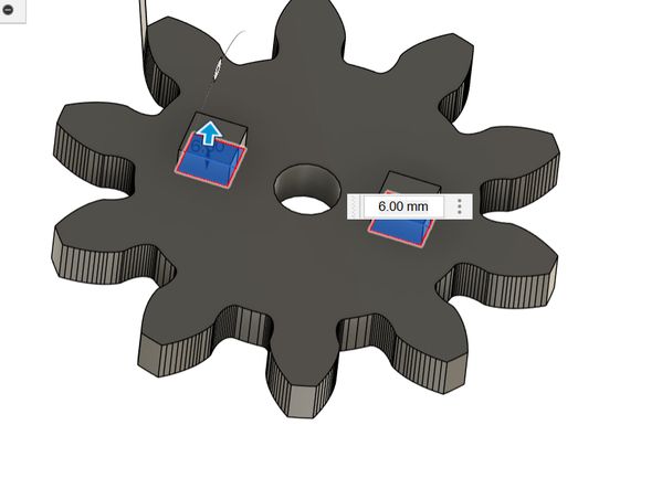
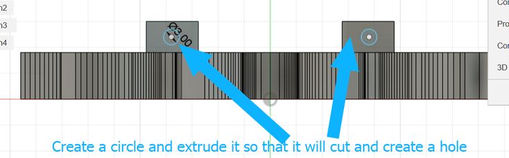
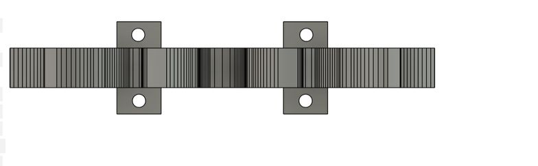
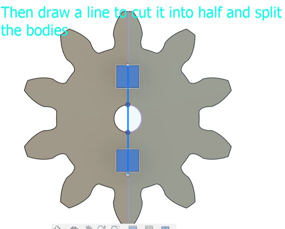
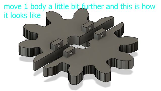
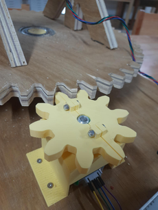
I couldnt directly 3d print that gear because our stepper motor had a head so, which prevented a single, solid 3D-printed gear from being directly mounted. So i tweaked the design a little where I split it into 2 parts and it comes together and gets connected via screwholes.
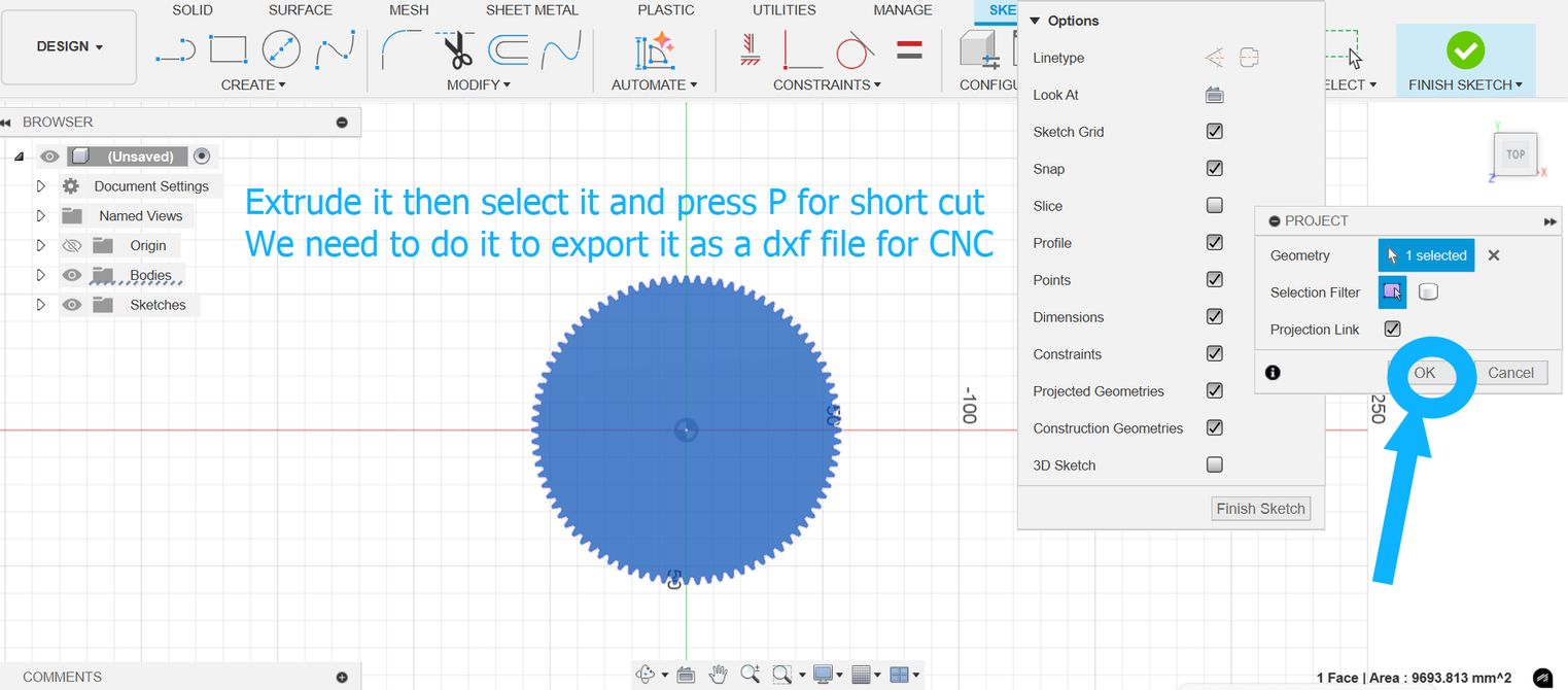
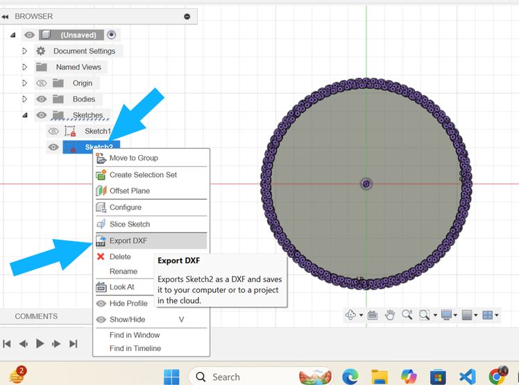
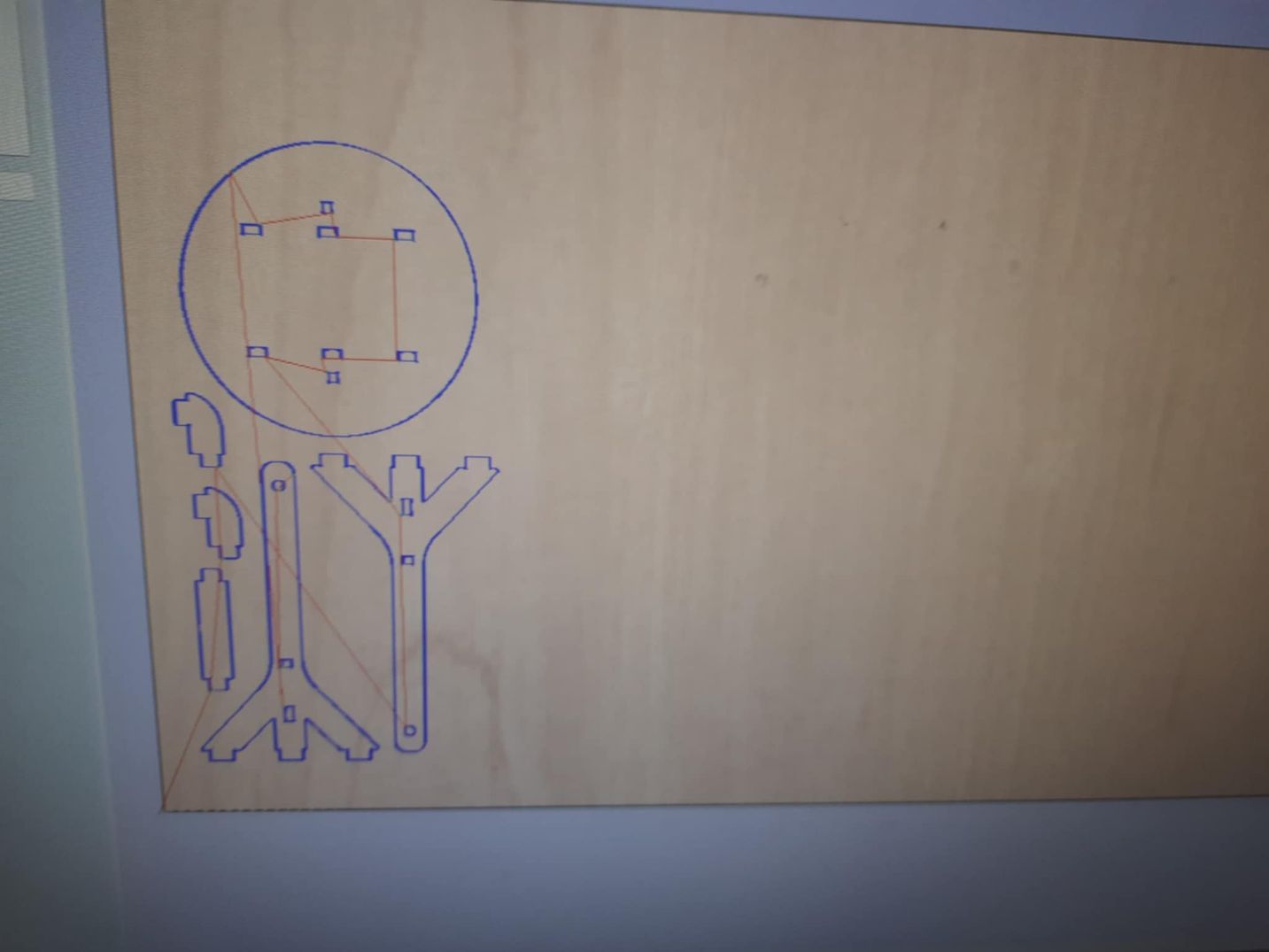
Then I CNCed and used laser cutting for the big gears. This is how they turned out!
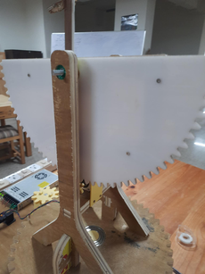
This is the side motors enclosure to hold it still. The side motor worked with a laser cut gear(bigger one) and the smaller giving it torque
This is a video of it working
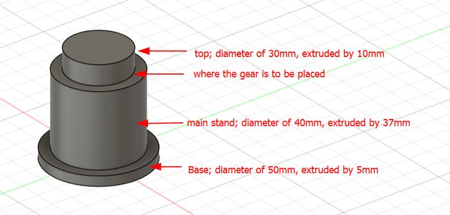
Base support
This is the design we made for the base support and it was 3d printed.
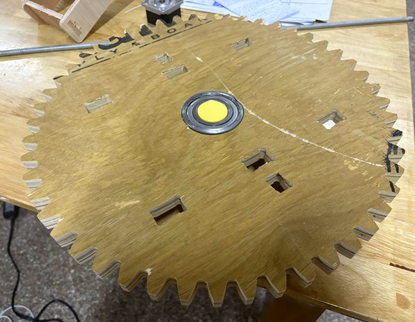
How it turned out attached to the base gear:
Electronics
Components
We will be using stepper motors in order to be able to move the telescope. Let's undertsand the components needed first.
Nema 17 stepper motor
A stepper motor is basically an electric motor whose shaft spins by executing steps, or by moving by a predetermined number of degrees, unlike a brushless DC motor which rotates continously. This function, which is made possible by the internal design of the motor, eliminates the need for a sensor by enabling one to determine the precise angular position of the shaft by counting the number of steps taken. It is also suitable for a variety of applications because of this property. I went through this website to better understand how it works.
LRS-350-24 transformer
The Mean Well LRS-350-24 is an AC to DC switching power supply that delivers 350.4W of power at 24V DC with a current rating of 14.6A.
The LRS-350-24 receives AC from a wall outlet which is converted into DC through a process called rectification. Capacitors are used to smooth out the DC voltage to reduce fluctuations. To control the amount of output delivered, a very high speed switch is turned on and off continuously. A feedback loop monitors the output voltage and adjusts the switching to maintain a stable 24V DC output. There is also a built-in fan to prevent overheating.
TinyG v8
The TinyG project is a high performance, USB based CNC 6-axis controller that supports XYZ linear and ABC rotary axes with 4 motor outputs. It is designed for small CNC applications and other applications that require highly controllable motion control. TinyG is meant to be a complete embedded solution for small or medium motor control. -Website
We will basically be using the TinyG to control multiple stepper motors using G-code.
Power source Switch IEC-320 C-14 AC Power Entry Module
UGS
This is the application we will be using to send G-code to TinyG.
Click on this link to download UGS.
This will take you to a page with various download options. Click on the one with your operating system.
Programming
Now, lets connect the components.
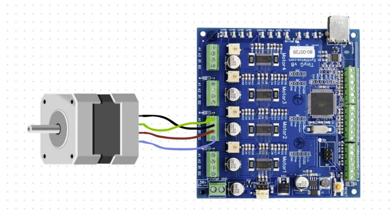
This is the connection we made between the Nema 17 stepper motor and the TinyG.
This is the pinout of LRS-350-24.
![]()
Connect V+ and V- to the ground and VCC of the Tiny G.
Connect the wires labled GND, L, and N to the gound, line, and neutral wire of the power entry module which will then be connected to the wall socket for the AC supply.
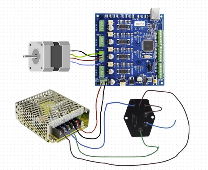
For reference, this is how the components should be connected. I got it from Ngawang Pemo's documentation. Thank You ashim!
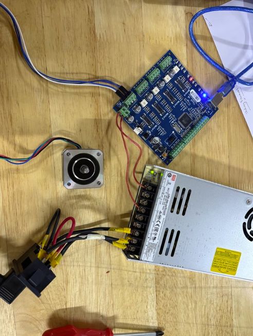
Yay! I connected it!
Now, we can start using UGS to control the two stepper motors. Here is how it turned out.
You can access the files here
Design files for gears