Group Assignment
Embedded Programming week
In this week group Assignment, we look forward to a trying out different microcontrollers available in the lab. For now we have decided these three microcontroller. The aim is not just to test this controller but also to understand their specifications such as their number of pin configurations, programming processs and how each of this controllers are different. Enabling us to know more about these boards.
For this Assignment we will be using the Arduino IDE to write code, compile, debug and to upload it to the board.
The boards that we look forward to test for this group assignments are:
- Arduino Uno
- ATTINY 44
- Esp32
Arduino Uno:
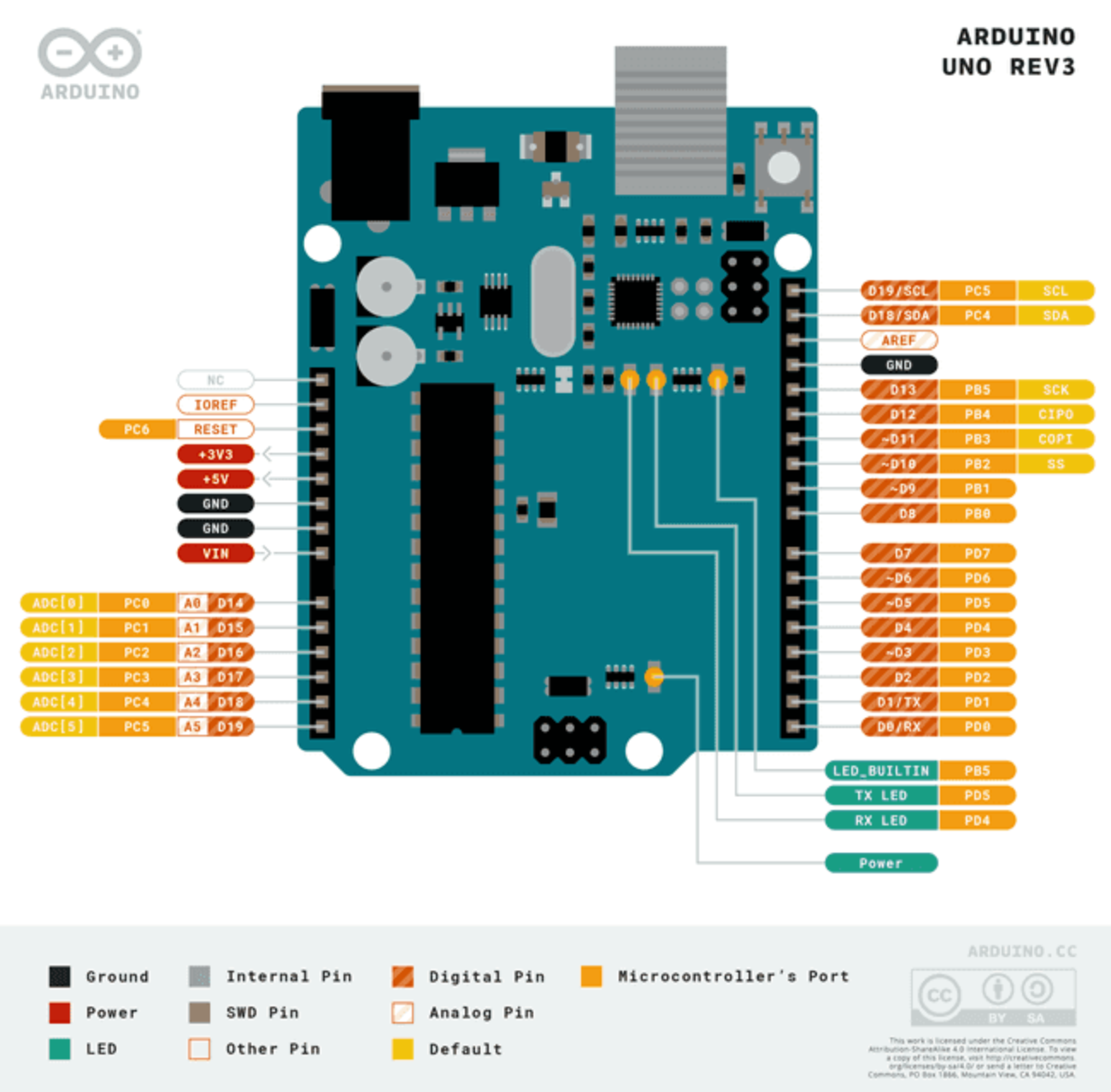
Arduino UNO R3 Specifications
Board
| Name | Arduino UNO R3 |
|---|---|
| SKU | A000066 |
Microcontroller
| Component | Specification |
|---|---|
| Microcontroller | ATmega328P |
| USB Connector | USB-B |
Pins
| Feature | Specification |
|---|---|
| Built-in LED Pin | 13 |
| Digital I/O Pins | 14 |
| Analog Input Pins | 6 |
| PWM Pins | 6 |
Communication
| Protocol | Supported |
|---|---|
| UART | Yes |
| I2C | Yes |
| SPI | Yes |
Power
| Feature | Specification |
|---|---|
| I/O Voltage | 5V |
| Input Voltage (nominal) | 7-12V |
| DC Current per I/O Pin | 20 mA |
| Power Supply Connector | Barrel Plug |
Clock Speed
| Processor | Speed |
|---|---|
| Main Processor | ATmega328P 16 MHz |
| USB-Serial Processor | ATmega16U2 16 MHz |
Memory
| Component | Specification |
|---|---|
| ATmega328P | 2KB SRAM, 32KB FLASH, 1KB EEPROM |
Dimensions
| Feature | Specification |
|---|---|
| Weight | 25 g |
| Width | 53.4 mm |
| Length | 68.6 mm |
For more detail here
Arduino Uno is the most popular development board for any beginner who wants to try in electronics and embedded programming.
Arduino UNO is a microcontroller board based on the ATmega328P. It has 14 digital input/output pins (of which 6 can be used as PWM outputs), 6 analog inputs, a 16 MHz ceramic resonator, a USB connection, a power jack, an ICSP header and a reset button.
Setting up Arduino for Test.
For this assignment, our main aim is know about the board and to procedure program it. This can be helpful to know about the board and the pin configuration, can be helpful to finalize the microcontrollor for the final Project
Of the tools necessary to upload the code to a board are.
- Microcontrollers : Arduino, ESP32, ATTINY 44
- USB cable (computer to the board)
- Programmer
- Computer with Arduino IDE.
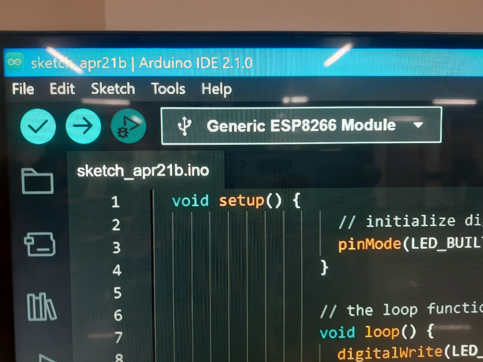
For this activity, we will be using the blink code which will be available in the Arduino IDE. Follow this path File > Examples > Basics > blink
The code is given below:
                void setup() {
                    // initialize digital pin LED_BUILTIN as an output.
                    pinMode(LED_BUILTIN, OUTPUT);
                  }

                  // the loop function runs over and over again forever
                  void loop() {
                    digitalWrite(LED_BUILTIN, HIGH);  // turn the LED on (HIGH is the voltage level)
                    delay(1000);                      // wait for a second
                    digitalWrite(LED_BUILTIN, LOW);   // turn the LED off by making the voltage LOW
                    delay(1000);                      // wait for a second
                  }
Before you upload your code to the board, there are two things that we have to do to make sure that all the configuration for the specific microcontroller is done.
Board Selection from tool tab
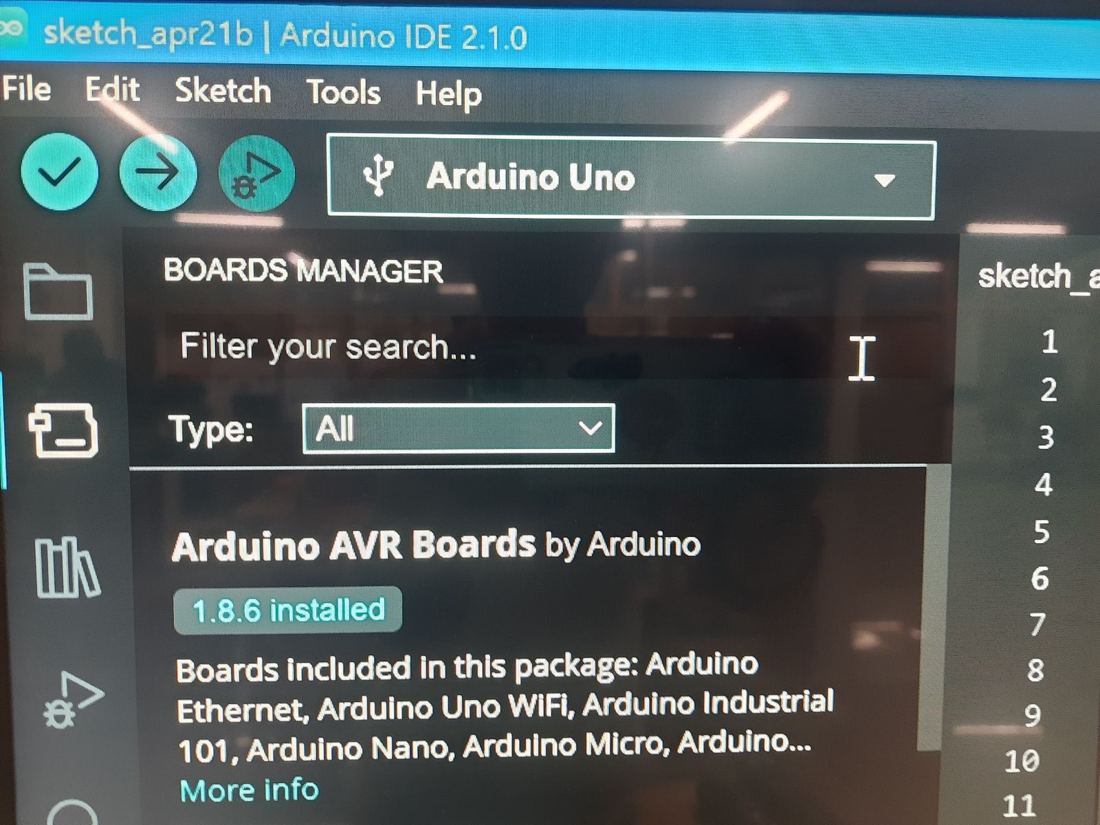
Port Selection from the tool tab: port where the USB from the micro controller is connected to computer. And also connect the Arduino with the USB
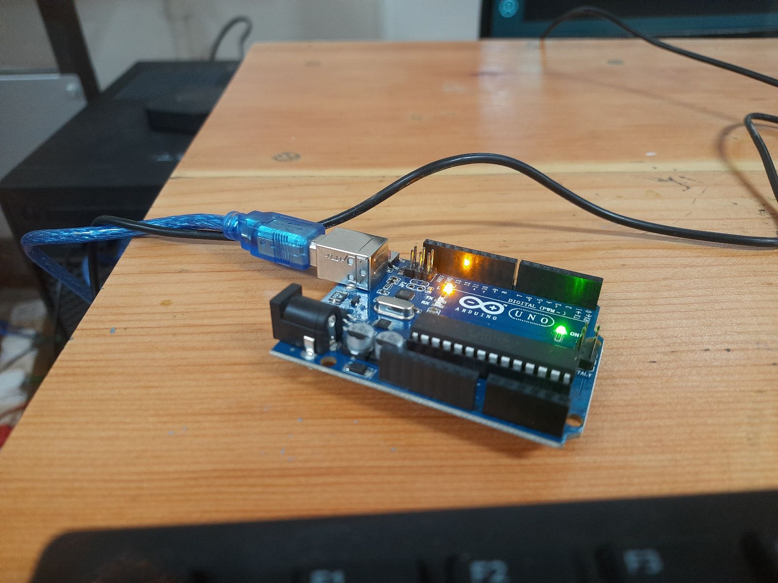
Output:
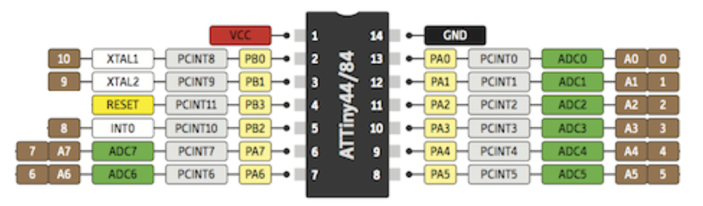
ATTINY 44:
| Feature | Specification |
|---|---|
| Program Memory Size (KB) | 4 |
| RAM | 256 |
| Data EEPROM (bytes) | 256 |
| Pin Count | 14 |
| Operation Voltage Max (V) | 5.5 |
| Operation Voltage Min (V) | 1.8 |
| ADC Channels | 8 |
| Zero Cross Detect | False |
| Number of Comparators | 1 |
| SPI | 1 |
| I2C | 1 |
| Standalone PWM | 4 |
| Low Power | No |
For more detail: Link
ATtiny (also known as TinyAVR) is a subfamily of the popular 8-bit AVR microcontrollers, which typically has fewer features, fewer I/O pins, and less memory than other AVR series chips. The first members of this family were released in 1999 by Atmel (later acquired by Microchip Technology in 2016).
We used a circuit boardwhich was fabricate by students in the lab, we will be using Arduino as ISP to program the Attiny 44 as shown below.
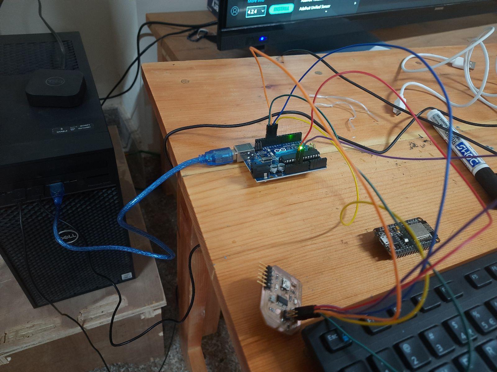
To make Arduino as ISP we will upload the code from the example to program the Arduino to act as an ISP.
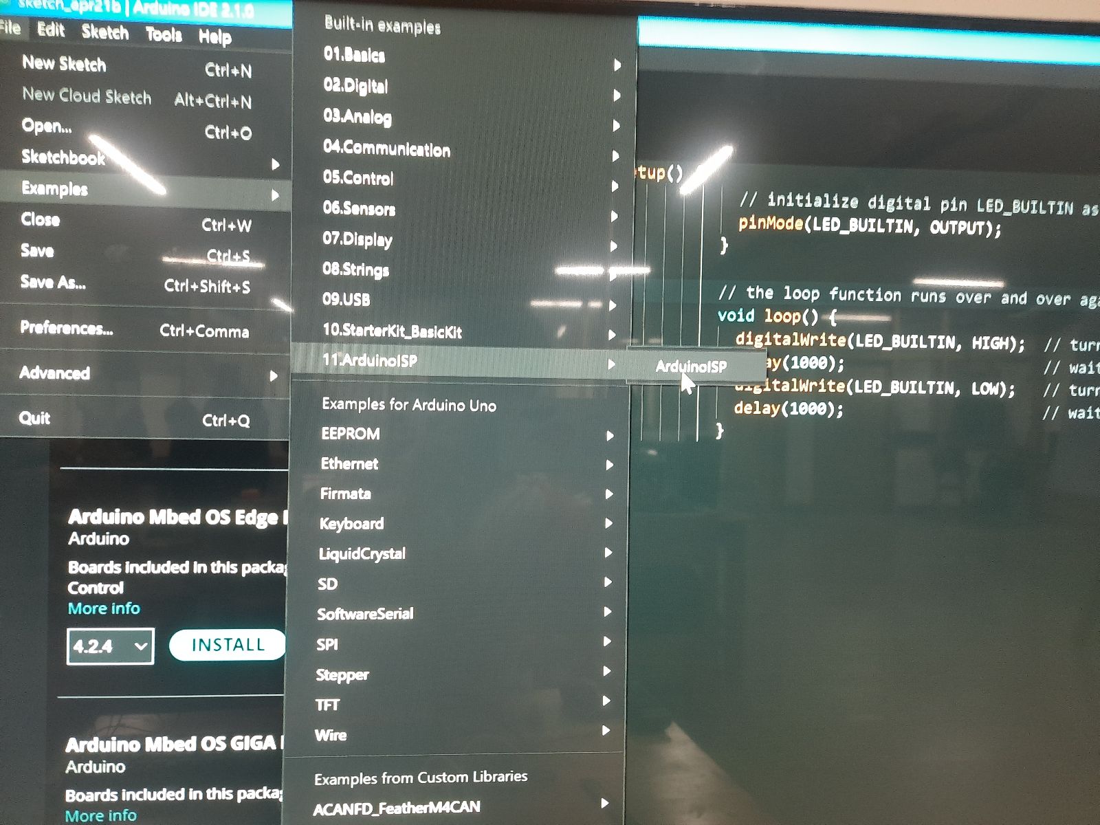
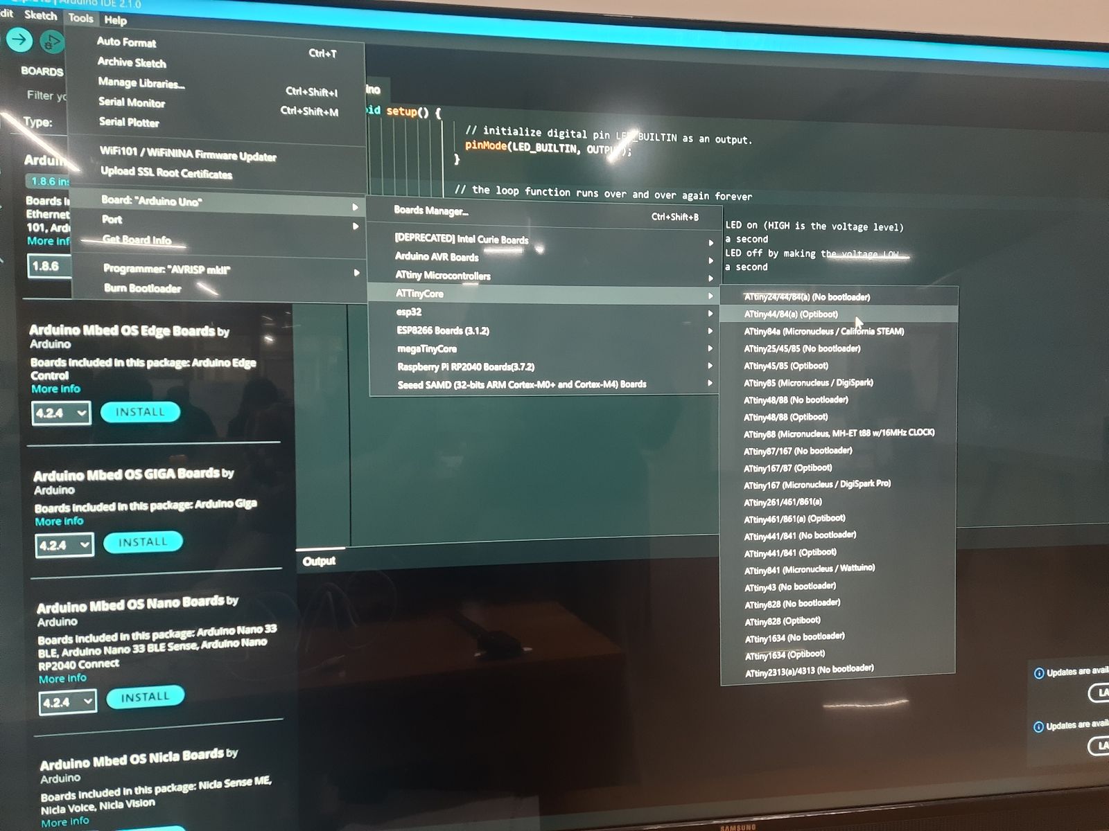
Make sure to select the right board and port while uploading the code.
                void setup() {
                    // initialize digital pin LED_BUILTIN as an output.
                    pinMode(8, OUTPUT);
                  }

                  // the loop function runs over and over again forever
                  void loop() {
                    digitalWrite(8, HIGH);  // turn the LED on (HIGH is the voltage level)
                    delay(1000);                      // wait for a second
                    digitalWrite(8, LOW);   // turn the LED off by making the voltage LOW
                    delay(1000);                      // wait for a second
                  }
The programable Led is connected to I/O pin 8.
Output
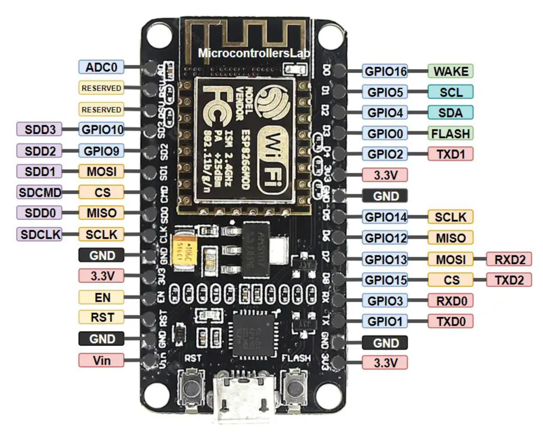
ESP8266
| Feature | Specification |
|---|---|
| Model | NodeMCU ESP8266 |
| Type | ESP8266 |
| Processor | Tensilica L106 Single-Core |
| Clock Frequency | 80 MHz (up to 160 MHz) |
| SRAM | 160 kB |
| Memory | 4 MB (Flash) |
| Wireless Standard | 802.11 b/g/n |
| Frequency | 2.4 GHz |
| BT Wireless Connection | Not Supported |
| Data Interfaces | UART / I2C / SPI / ADC |
| Operating Voltage | 3.3V (via 5V microUSB regulator) |
| Max. Current Draw per GPIO | 12 mA |
| Operating Temperature | -40°C to 125°C |
ESP32 is a chip that provides Wi-Fi and (in some models) Bluetooth connectivity for embedded devices – in other words, for IoT devices. While ESP32 is technically just the chip, the modules and development boards that contain this chip are often also referred to as “ESP32” by the manufacturer.
To program the esp32 we can use the type B to A USB and write code on the Arduino IDE.
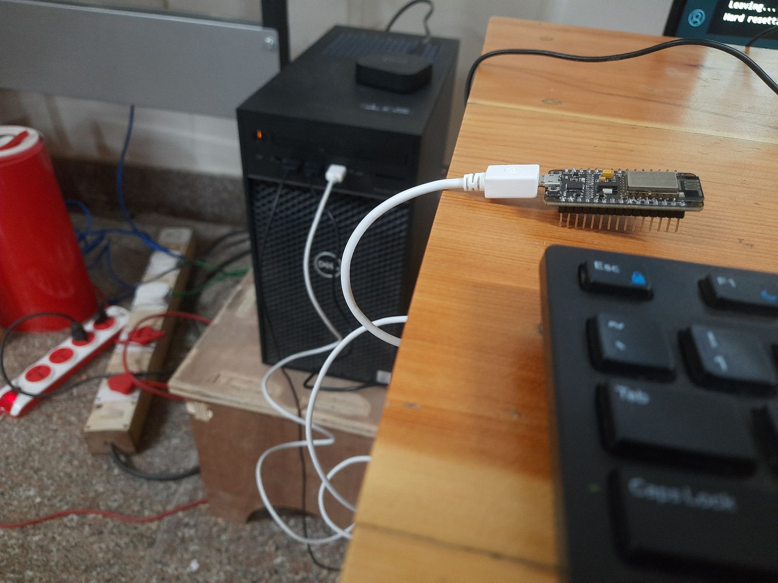
Make sure you select the right board and port while uploading the code:
                void setup() {
                    // initialize digital pin LED_BUILTIN as an output.
                    pinMode(LED_BUILTIN, OUTPUT);
                  }

                  // the loop function runs over and over again forever
                  void loop() {
                    digitalWrite(LED_BUILTIN, HIGH);  // turn the LED on (HIGH is the voltage level)
                    delay(1000);                      // wait for a second
                    digitalWrite(LED_BUILTIN, LOW);   // turn the LED off by making the voltage LOW
                    delay(1000);                      // wait for a second
                  }