Week 5: 3D Scanning and Printing
Group Assignment
- Test the design rules for your 3D printer(s)
- Document your work on the group work page and reflect on your individual page what you learned about characteristics of your printer(s)
3D printer
Our group assignment this week required us to test the design rules for our 3D printer. The 3D printer at our lab is the Prusa i3 MK3.
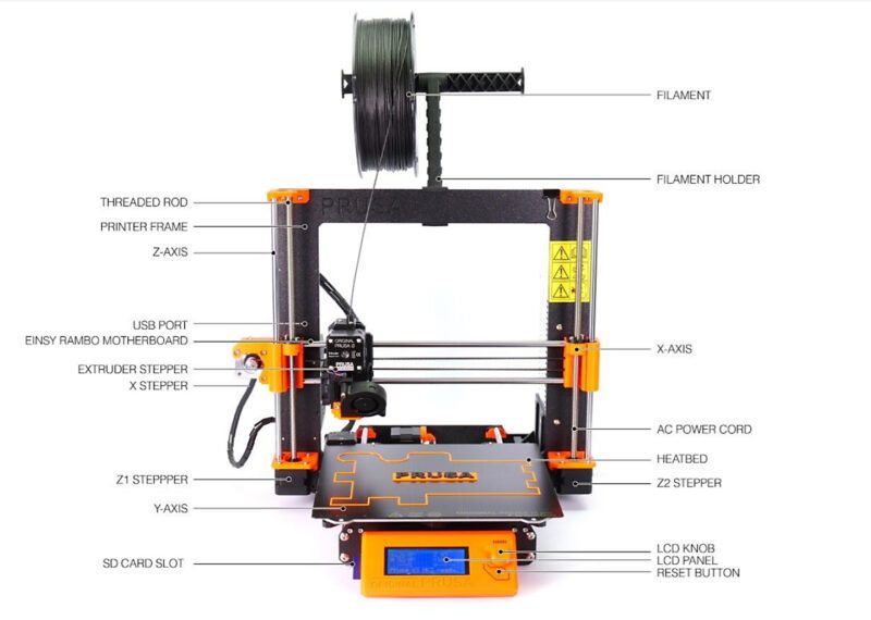
Machine and Specifications
Build volume : 250 x 210 x 210 mm | 9.84 x 8.3 x 8.3 in
Layer height : 0.05 – 0.35 mm
Max travel speed : 200+ mm/s
Max hotend/heatbed temp : 290 °C / 120 °C (572 °F / 248 °F)
Mainboard : Einsy RAMBo 8-bit board
MMU2S/3 support : Yes
Nozzle diameter : 0.4mm (default) / other nozzle diameters supported
LCD screen : Monochromatic LCD
Print surface : Magnetic heatbed with removable PEI spring steel sheets
Cutting Tool Chuck : Collet method
Filament diameter: 1.75mm
Tutorial on how to 3D print
To test the design rules for our 3D printer, we used the All In One 3D Printer test.
If this is your first time using a 3D printer, you can follow along here.
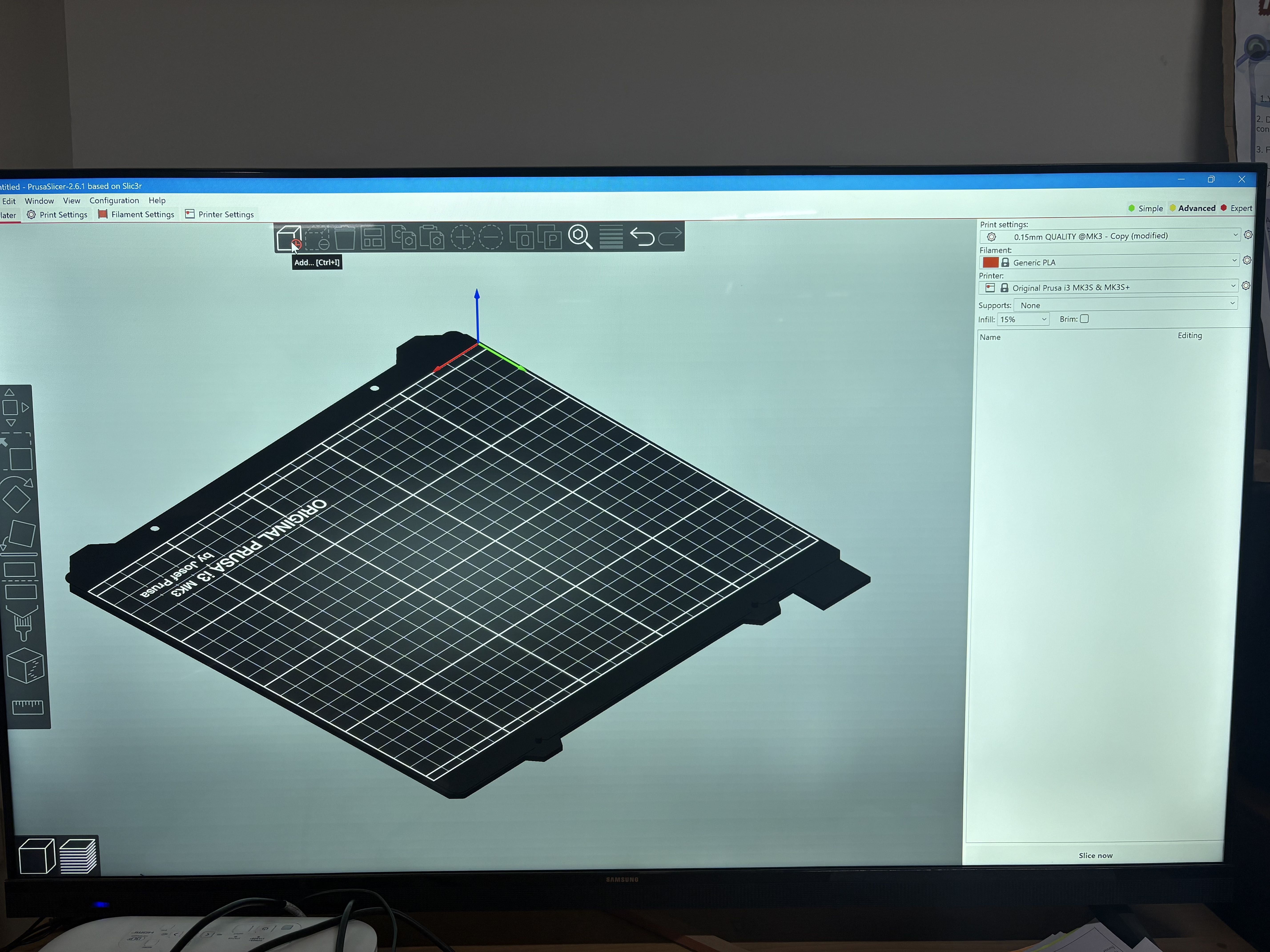
We are using the application Prusa slicer. This is what its workspace looks like.
Import your design.
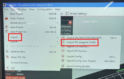
On the top, tap on the cube icon. You can also press 'Ctrl + I' to access it. This will allow you to select your SD card in which you want to store your design in G-code format.

Select your SD card.
On the toolbar, select the icon to place the bottom of the model to the base of the plate.
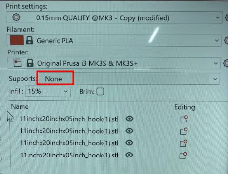
Make the necessary changes to the print settings. Make sure to set the 'supports' to none, since we are testing the 3D printing right now.
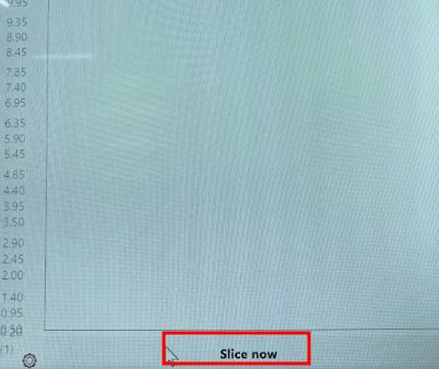
Tap on 'slice now'.
Export your G-code.
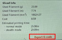
Now, take your SD card and insert it in your printer.
You can start printing now and edit the settings as well.
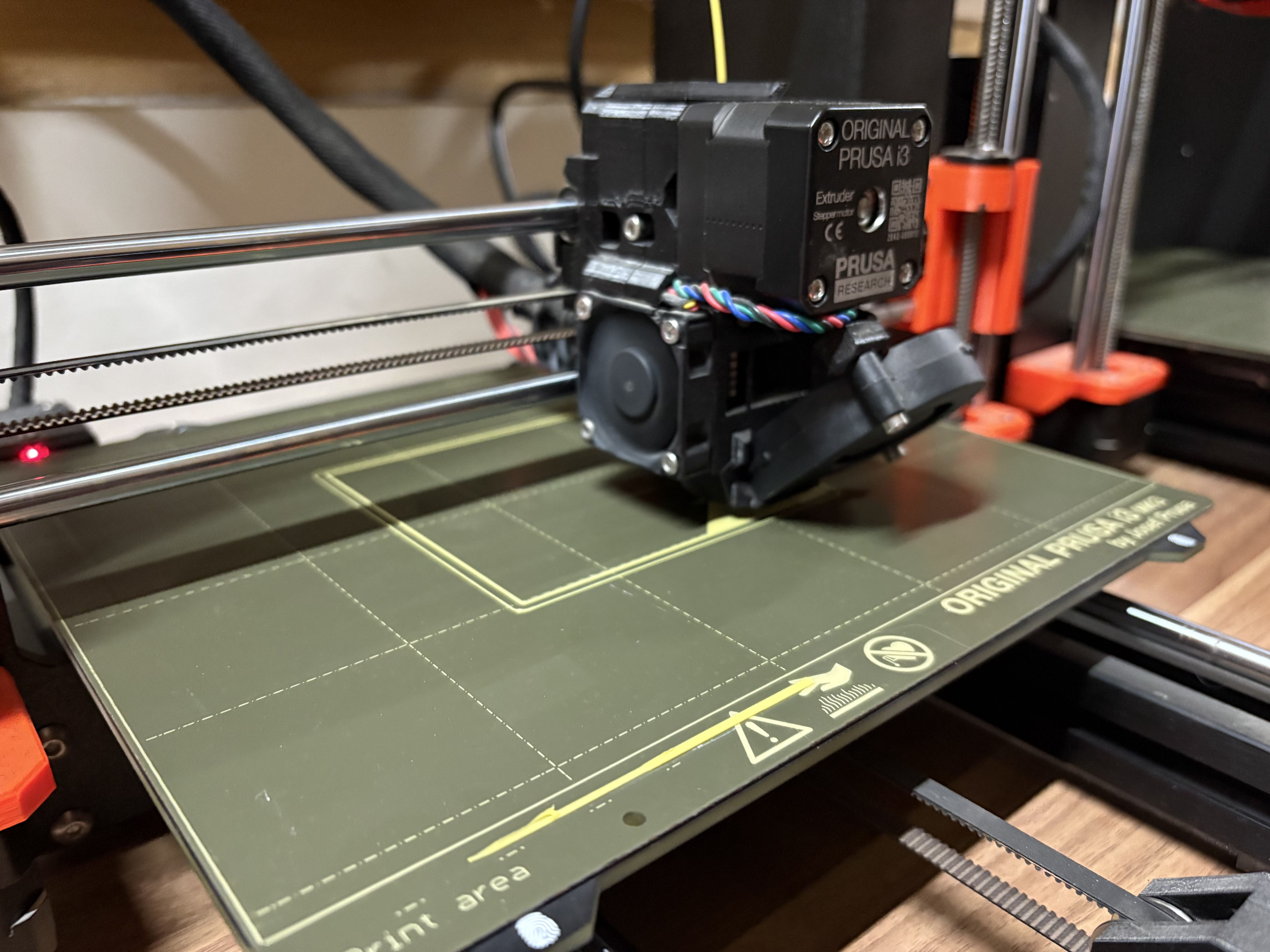
Here is a picture of us working on it!
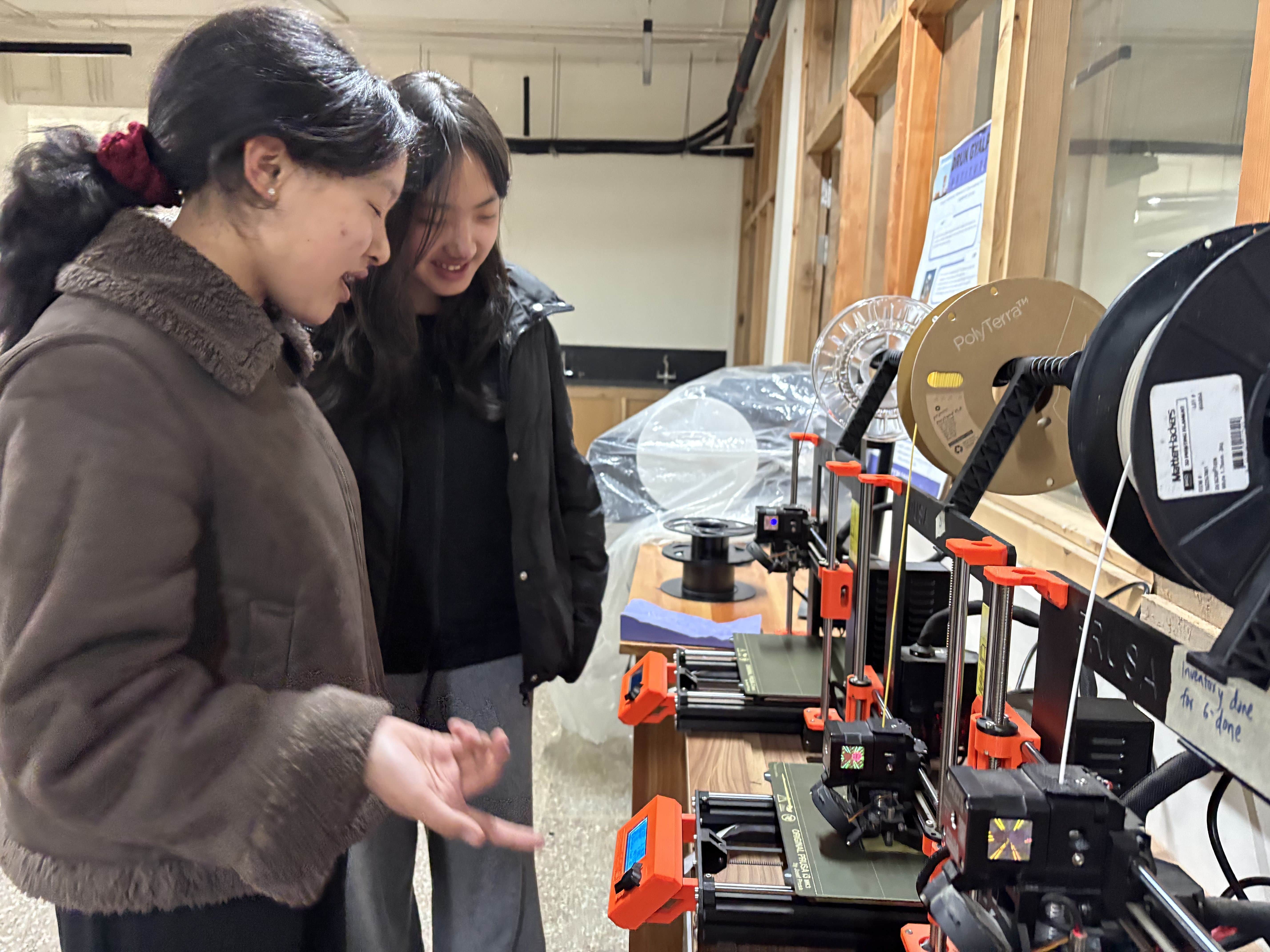
Observation
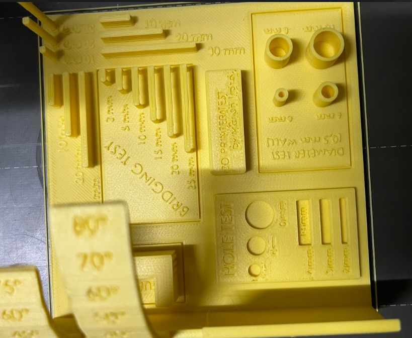
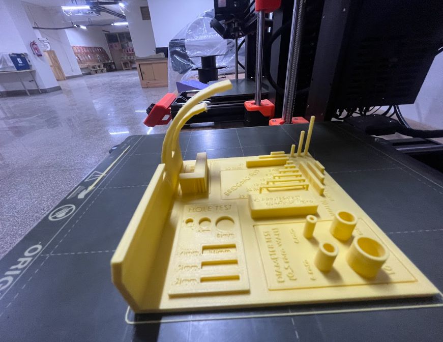
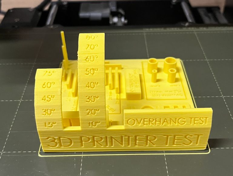
Here is how the results turned out!
Diameter test
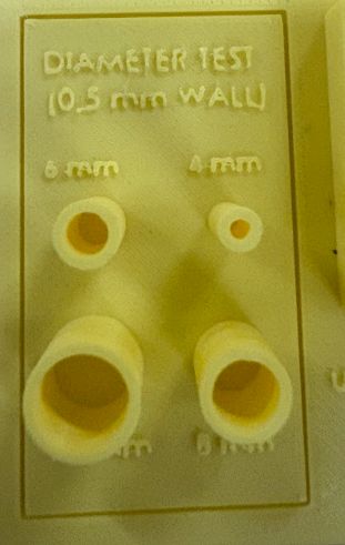
All the 4 diameters that we tested the printer out with turned out pretty good. All of them were pretty sturdy and smooth. We can conclude that our printer is very good with printing holes.
Hole test
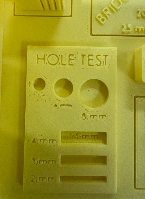
All three of the holes turned out very good. However, the letters indicating the size of the holes were not visible.
Bridging test

This test assesses the printer's ability to bridge gaps between two points without the need for support structures. The filament turned out pretty smooth and sturdy for 2mm, 5mm, and 10mm. However, as the length increased, the bridge became weaker. It was not as sturdy, and the filament was not well-filled. We can conclude that the filament deposition in mid-air not being stable suggests that the printer may struggle with maintaining consistent filament flow during bridging.
Overhang test
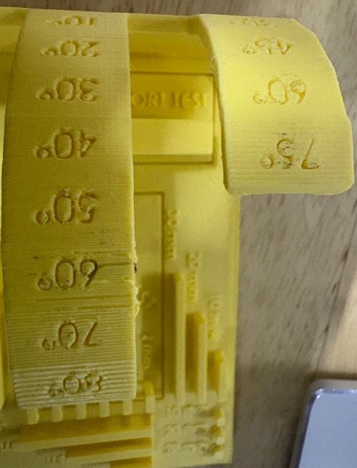
The Overhang Test evaluates a 3D printer's capability to produce overhanging structures without the need for additional support material. In the 10-degree increment overhang, the overhangs crossing 60 degrees came out very shaky, and the filament was not well-filled. For the 15-degree increment overhang, the print came out shaky after 45 degrees. In conclusion, the printer performed best before 50 degrees overhang.
Vertical pillar test
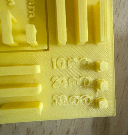
This test assesses a 3D printer's ability to accurately reproduce vertical features and evaluate dimensional accuracy and stability. As the height of the pillar increased, the stability also decreased. As you can see in the photo right above, the 20mm and 30mm pillar broke. This signifies our printer is unable to print tall, stable pillars. This could be due to issues with layer adhesion, printer calibration, or cooling.
Reflection
This group assignment was quite fun for all of us to work on. Since all of us had forgotten how to use the 3D printer at our lab, this assignment helped us learn it all over again. Understanding the limitations of our 3D printer will be very beneficial and helpful for future projects involving the 3D printer.
Thank You!!!