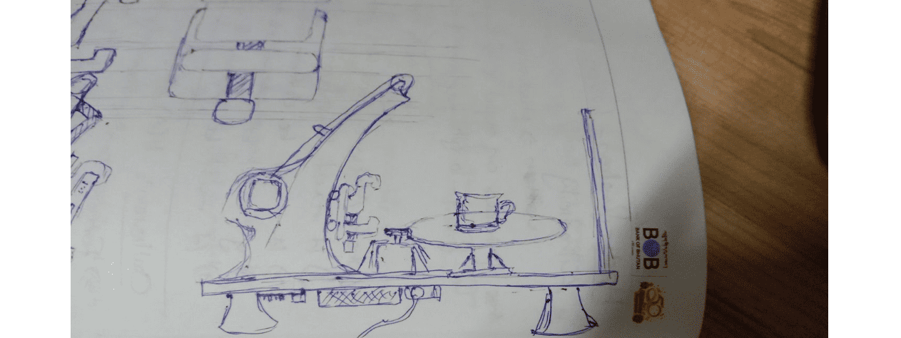
It’s machine design week!!! 😨 We started off by discussing potential ideas for a machine, and we agreed on creating a 3D scanner, since our lab doesn’t have one anymore. We had a group discussion and finally came up with this idea/sketch with the help of our local instructor. We also divided our roles.
The general idea is a rotating platform (to place your object), and an arm that holds your scanner, and can move the scanner up and down for better results.
For the programming part of the machine building, I took on the role of Programmer along with my friend Damzang for the stepper motor control system.
For this group assignment, I was responsible for:
The primary characteristic of a stepper motor is that it is an electric motor whose shaft spins by executing steps, or by moving by a predetermined number of degrees. This function, which is made possible by the internal design of the motor, eliminates the need for a sensor by enabling one to determine the precise angular position of the shaft by counting the number of steps taken. It is also suitable for a variety of applications because of this property.
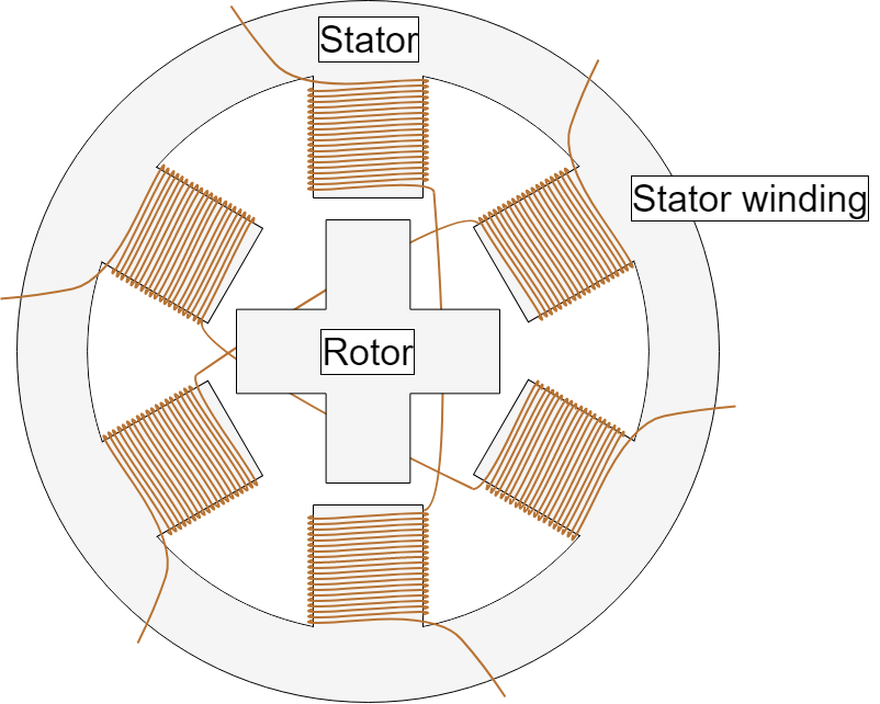
Like all electric motors, consist of a moving portion called the rotor and a fixed part called the stator. The rotor is made up of an iron core with variable reluctance or a permanent magnet, whereas the stator has teeth on which coils are strung. Later on, we shall delve further into the various rotor structures. A drawing of the motor's section with a variable-reluctance iron core as the rotor is seen in Figure 1.
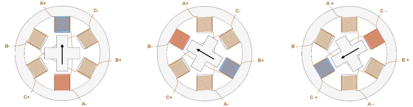
The current flowing in the coil generates a magnetic field by activating one or more of the stator phases, and the rotor aligns itself with this field. To reach the intended ultimate position, the rotor can be spun by a specified amount by applying different phases in a sequential manner. A diagram illustrating the operating principle is presented in Figure 2. Coil A is turned on initially, and the rotor is oriented to coincide with the magnetic field it generates. The rotor rotates 60 degrees clockwise to line up with the new magnetic field when coil B is energized. The same thing occurs upon energizing coil C. The stator winding's magnetic field's direction is indicated in the images by the colors of the stator teeth.
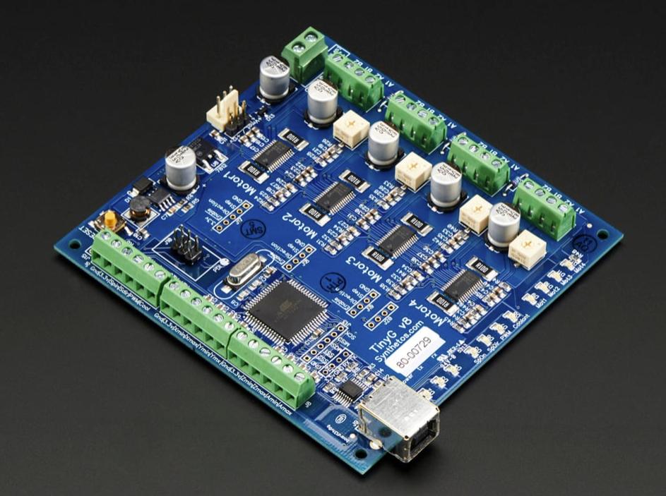
The TinyG project is a high performance, USB based CNC 6-axis controller that supports XYZ linear and ABC rotary axes with 4 motor outputs. It is designed for small CNC applications and other applications that require highly controllable motion control. TinyG is meant to be a complete embedded solution for small or medium motor control.
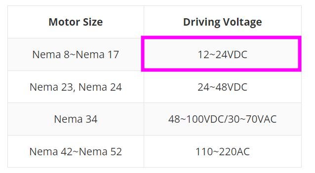
While exploring online for the different power sources required for different stepper motors, I came across this table and it was from a well documented site.
As we are using the Nema 17 motor driver, we would be needing a 24V power supply!!⚠️
It was really confusing for us to understand the connection between the Nema motor and TinyG board. So while I was exploring online, I found this really nice documentation done for TinyG and it also showed how to connect the TinyG to stepper motors!!
Here is a simple table that shows the coil pairs!!
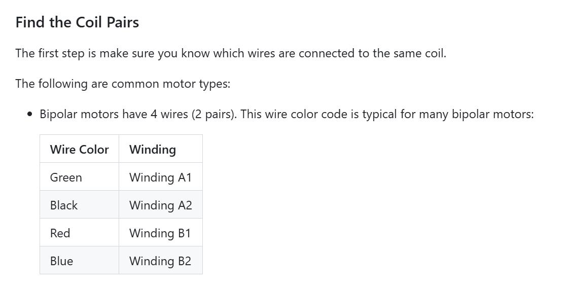
Note:The NEMA 17-size hybrid stepping motor can be used as a unipolar or bipolar stepper motor.
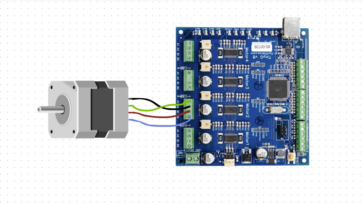
Here you can see the pinout of the stepper motor consisting of the 4 different colored coils.
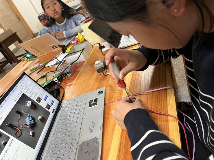
So, here is the connection we made between the Nema 17 stepper motor and the TinyG.
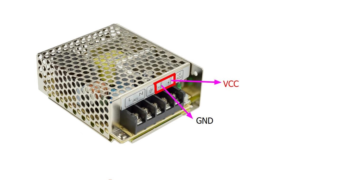
Connecting the power supply to the TinyG board was quite easy as we just had to connect the VCC and GND.
Here you can easily spot the VCC and GND
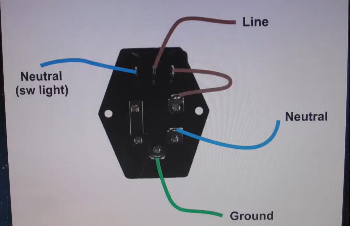
Now, the challenging part was connecting switch to the TinyG but with the help of this YouTube tutorial, it was quite fun and easy.
Here is the labelled diagram of a power entry module that I took from the video
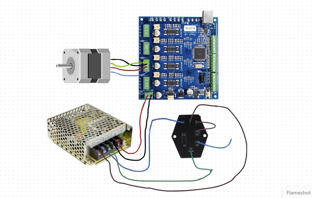
After connecting the power entry module and TinyG to the 24V power supply, here is the picture of the whole circuit!
We tried to program the DC stepper motor to begin with and for this we took reference from this site
These are the steps we followed to program the stepper motor.
Then we used a DC power supply between 12 and 30 volts capable of providing 4 to 15 amps.
After that we turned on the power supply and checked for correct voltage and polarity before connecting it to TinyG.
Note: Avoid overdriving the motors, it can lead to overheating and damage.
Once everything is connected and configured, test drive your stepper motor by sending movement commands through TinyG.
Check for smooth operation, correct direction, and appropriate speed.
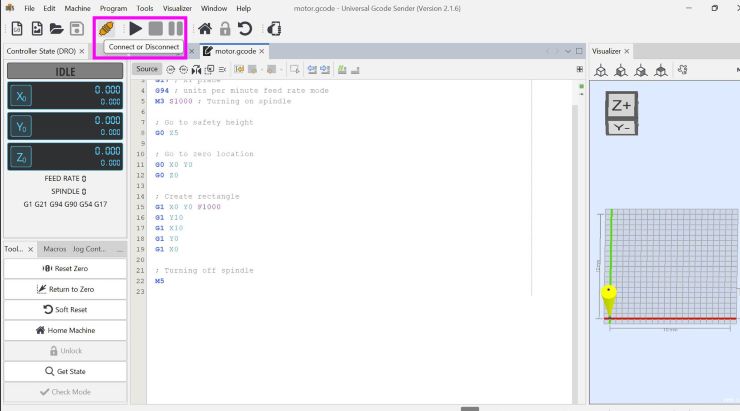
For the test drive, we tried with the code that was given in the reference documentation.
We uploaded this code g1 f400 x100
In the above G-Code,
G1: This is a standard G-code command that instructs the machine to move in a straight line from its current position to a specified point at a specified feed rate.
F400: This part of the command sets the feed rate or the speed at which the machine should move. The value 400 indicates a feed rate of 400 units per minute. This determines how fast the motor will spin.
X100: This part of the command specifies the target position along the X-axis where the machine should move to. In this case, it's instructing the machine to move to the X-coordinate of 100 units.
It worked!!
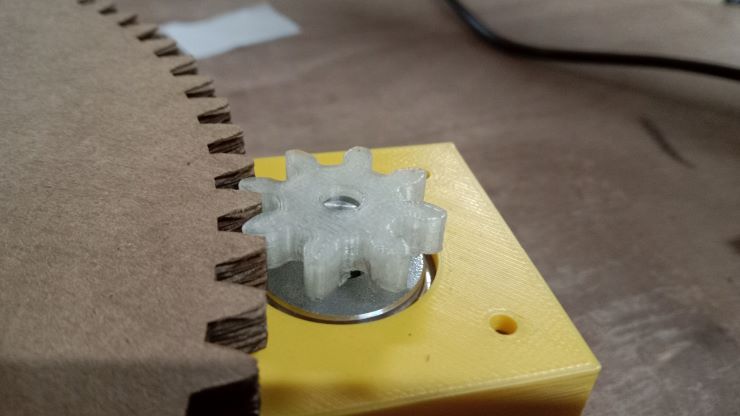
After the test, Thinley and Yangtshel made a gear for the stepper motor so we tried spinning with it.
Now, we did another test with the main gear for the platform. It was pretty smooth and simple.
After a few discussions, we changed our plans and decided to keep the platform for scanning on top of the stepper motor for more conveniency.
For our scanning machine, we are trying to control 2 motors in which the first motor will be used to rotate the platform and the second second motor which will be kept side-down to move the scanning platform of the object vertically.
While making the code, our main goal was to make the the scanner move up the y-axis by 2 units after every rotation of the platform to allow the object to be nicely scanned.
First we tried uploading the following code:
Each command starts with G1, which indicates a linear movement instruction. The format is G1 F<speed> X<position> Y<position>.
G1: Indicates a move command.F<speed>: Sets the feed rate, or the speed at which the tool moves.
X<position>: Sets the X-axis position.Y<position>: Sets the Y-axis position.
        g1 f40 y14
        g1 f50 x3
        g1 f40 y28
        g1 f50 x6
        g1 f40 y42
        g1 f50 x9
        g1 f40 y56
        g1 f50 x10
        g1 f40 y70
        g1 f50 x9
        g1 f40 y84
        g1 f50 x6
        g1 f40 y98
        g1 f50 x3
        g1 f40 y112
        g1 f50 x0
        g1 f40 y126
This worked, however the motor was spinning really fast and the scanning was
completed in a short amount of time resulting in an ineffective scan, so we tried testing different speeds for the motors and
settled on f20 for the y-axis and f40 for the x-axis.
Here is our updated code
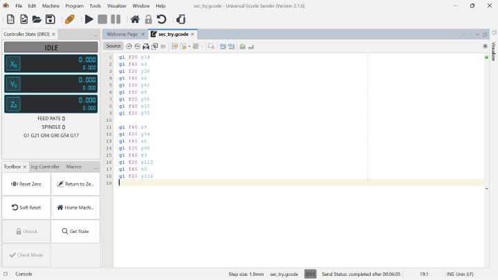
Each command starts with G1, which indicates a linear movement instruction. The format is G1 F<speed> X<position> Y<position>.
G1: Indicates a move command.F<speed>: Sets the feed rate, or the speed at which the tool moves. This is usually in units per minute (e.g., mm/min).X<position>: Sets the X-axis position.Y<position>: Sets the Y-axis position.Line-by-line explanation:
g1 f10 x14This moves the tool at a feed rate of 10 units to position X=14.
g1 f40 y-2This moves the tool at a feed rate of 40 units to position Y=-2.
g1 f10 x28Moves the tool at a feed rate of 10 units to position X=28.
This logic applies for the rest of the code..
The sequence shows a pattern of moving the scanner along the X and Y axes with specified feed rates,
changing positions at each step. The coordinates and feed rates indicate specific paths and speeds for
the scanner's movement. Each G1 command specifies a move operation, with the tool moving to a
new X or Y position at the specified feed rate.
To see how this code worked, see our video for our 3D scanner.
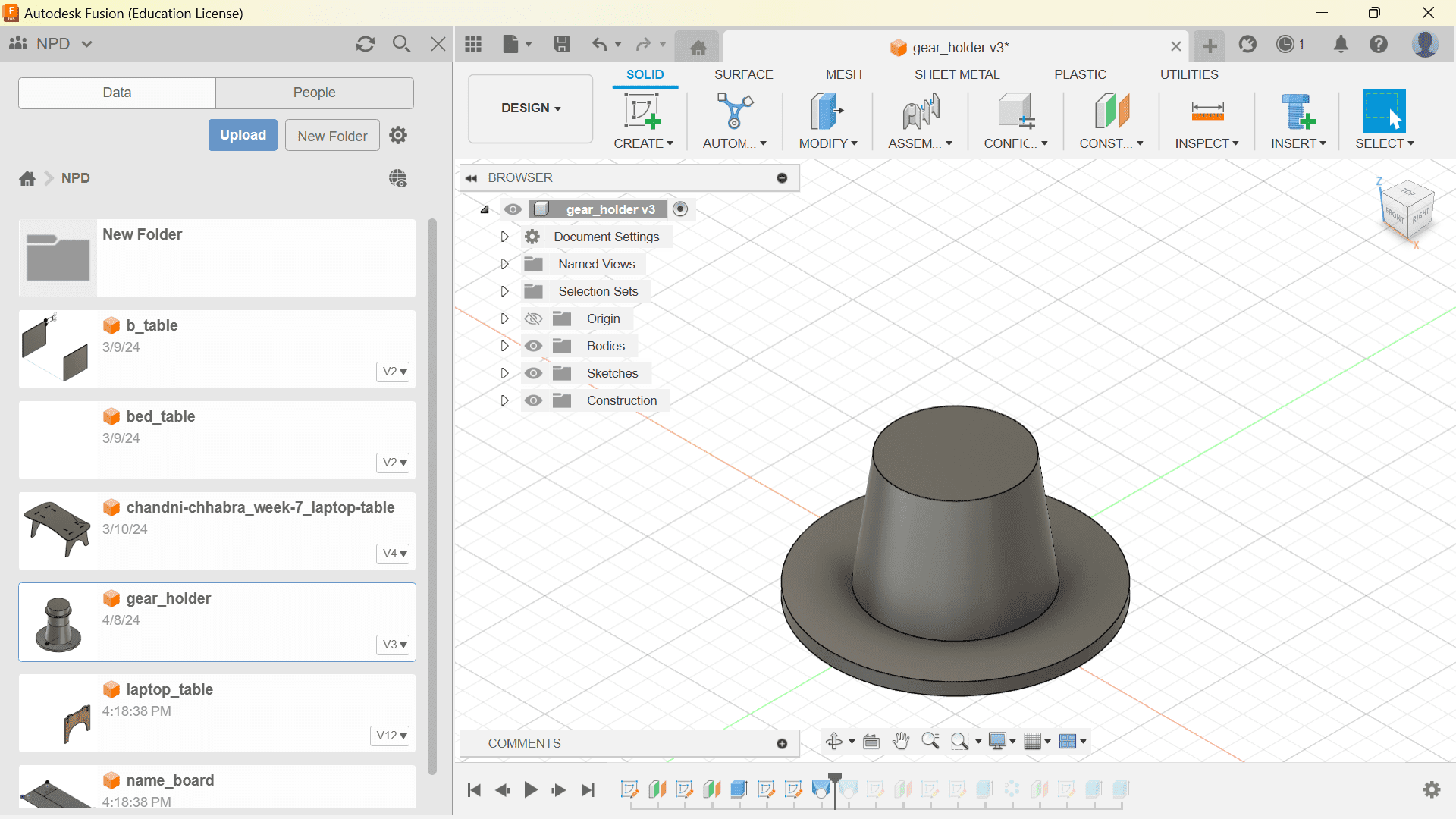
After we were done with the programming part, I contributed a bit to the designing part. For the designing part, I designed a holder for the platform in Fusion 360.
First I made the sketch for the base and extruded it.
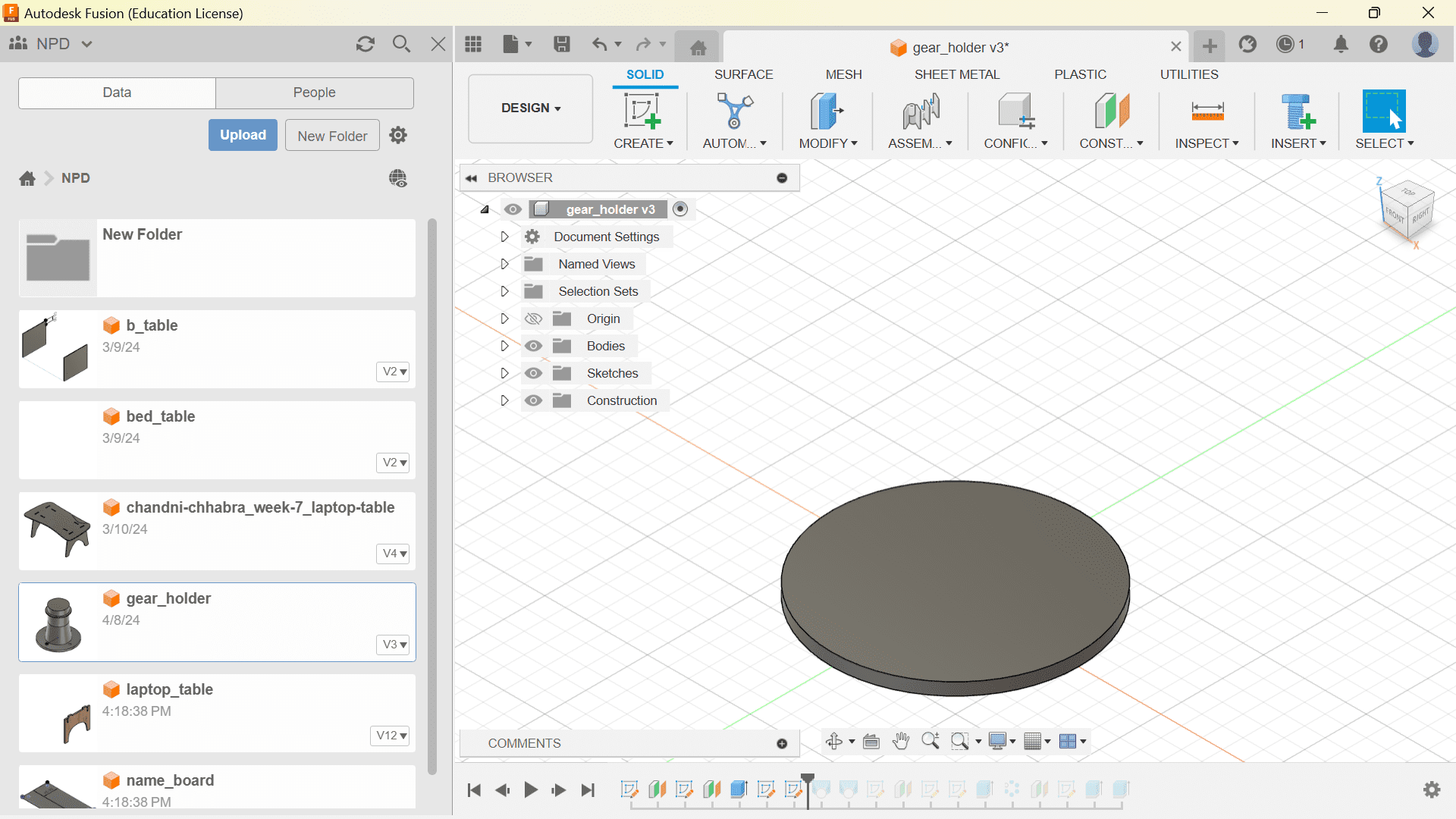
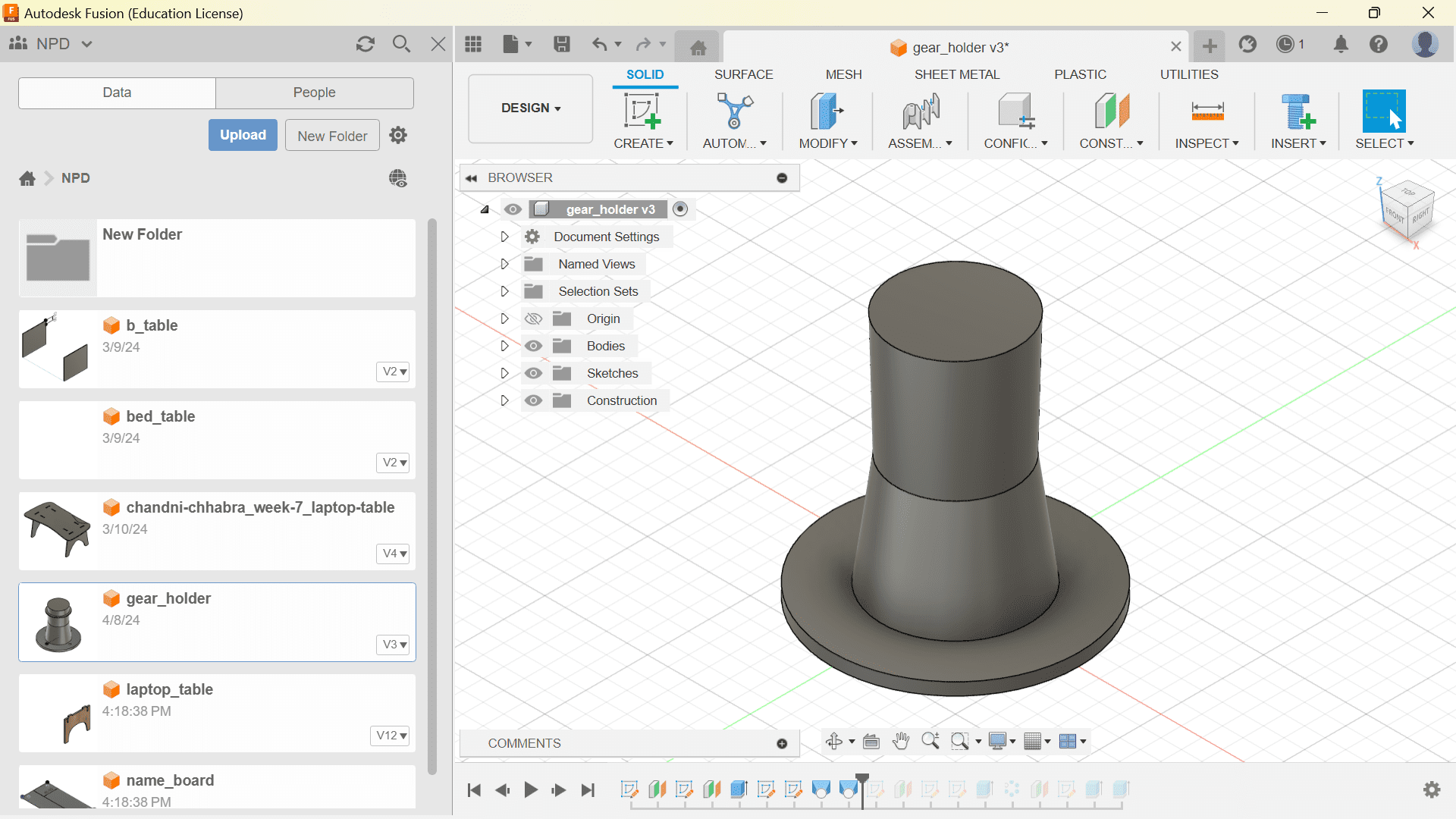
Then I made an offset plane and made the first leg of the holder.
I made another offset plane sketch for the other leg whose diameter is same as the diameter of the bearing.
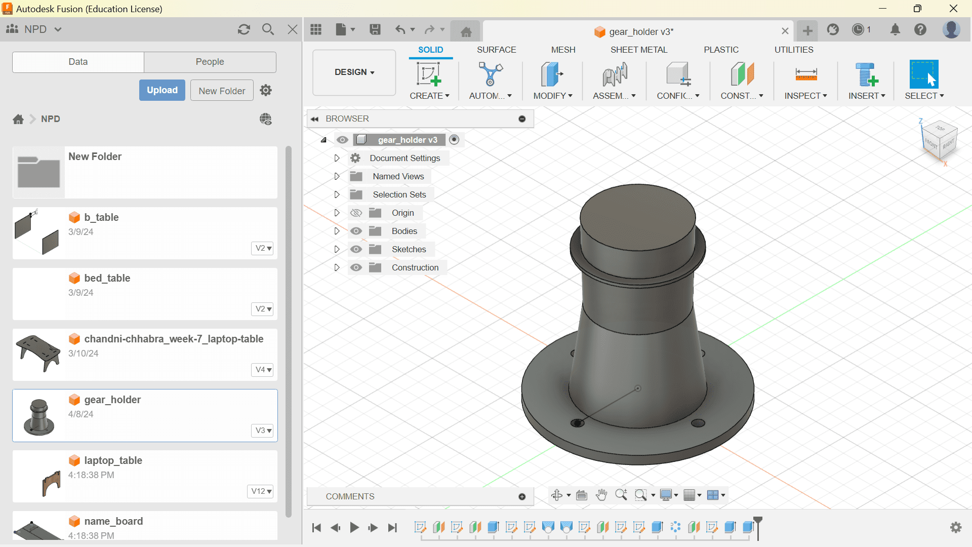
Lastly, I made a the drill holes and support which holds the platform to the exact height as the stepper motor.
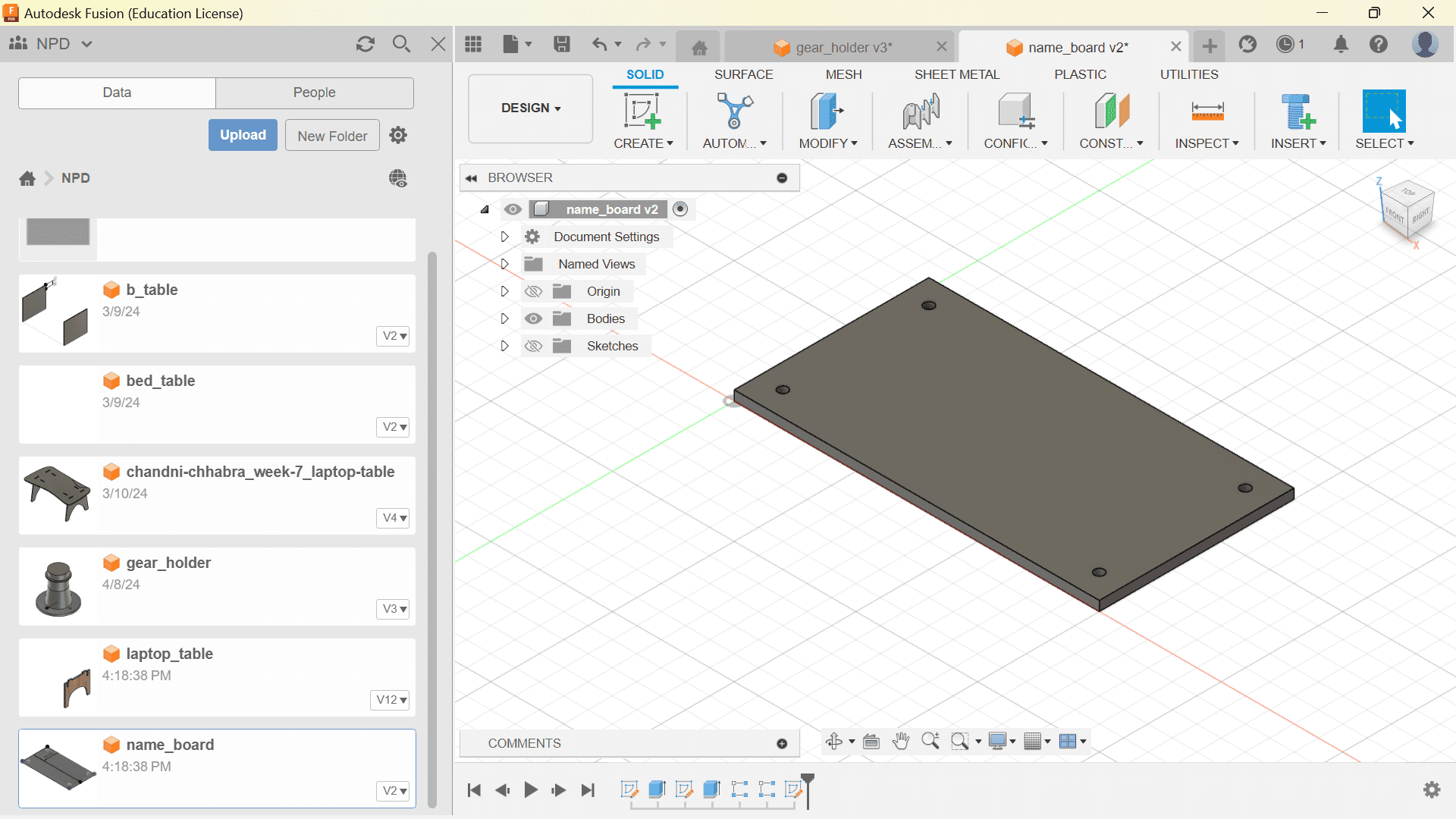
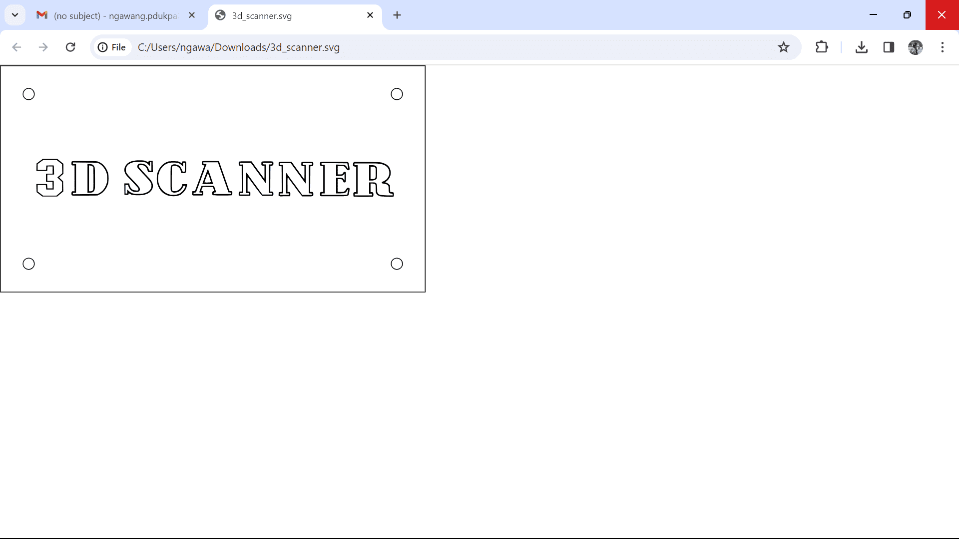
After getting done with this design, I made a design for the machine name.
I started designing the outline and drill holes in fusion and then added the texts in Inkscape
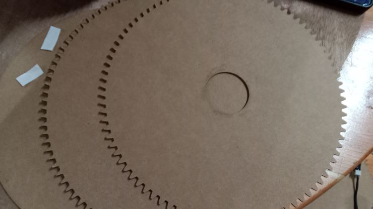
Lets now see how we assembled our machine.
Lets make our gears and adjust them in place.
Now the arm!
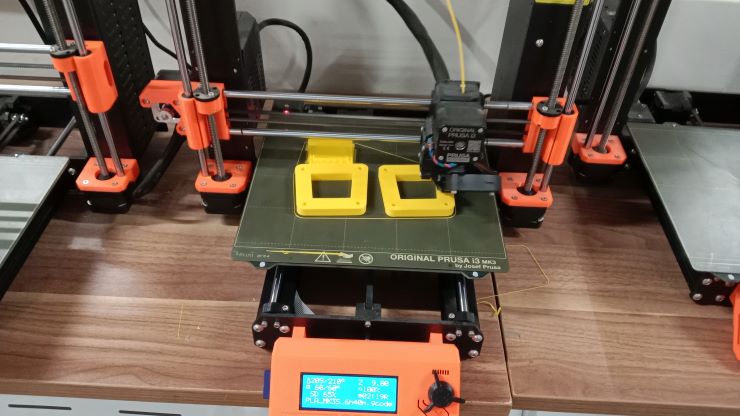
 The wooden arm that we printed didnt come out that good so we decied to 3D print the arm so that it can be smoother.
 Now we started importing all the designs together.


Personally, I gained a deeper understanding of stepper motor programming and control systems, enhancing my skills in research, coding, testing, and debugging. Working as a team to build a 3D scanner required effective communication and task allocation, which was both challenging and rewarding. We encountered several technical issues, such as wiring complexities and motor synchronization, but we overcame these through collective problem-solving and resourcefulness. The project highlighted the importance of teamwork and proper planning, and it also provided insights into areas for improvement, such as optimizing motor speed and enhancing design stability. Overall, the experience was invaluable in reinforcing the principles of mechanical design and automation.