This week we learned about Computer Numerical Control machining. I learned a lot about how it operates through Prof. Neils classes which were very helpful and insightful to me. However I couldnt attend the local session because of the timing which is not flexible. I go to morning learning experiences and do fabacademy assignments during the afternoons but our sessions are alloted during morning (UTC +6 BTT). That is the reason that I asked our regional instructor-The MOAT(Master of all time) as he likes to call himself sir Rico to record it so that I can watch it and gain their tips and advices and knowledge too. If there are doubts, I reach out to them through Mattermost.
Just like always I created a roadmap for myself, to track my progress and this is how it looks like!

Table of Contents
- Group Assigment
- Individual Assignment
- Complete your lab's safety training
- Test runout, alignment, fixturing, speeds, feeds, materials and toolpaths for your machine
- Document your work to the group work page and reflect on your individual page what you learned
- Workspace: 2400mm x 1800mm
- Speed: Operates at 10000 RPM
- Software: Utilizes ShopBot Control Software
- Fixture: Clamps are used to attach cutting material
- Setting Origins: X and Y axes set via ShopBot3 software; Z-axis requires manual zeroing using a metal plate and clip.
- Safety features: Emergency stop button, reset button, start button, main control box.
- "look,listen and smell" during operations for smoke or strange smells!
- Wear (PPE)personal protective equipments: protective goggles and ear defenders.
- Never leave the equipment running unattended.
- Keep hands, hair, and attire away from moving components.
- Use suitable feed rates and spindle speeds for different materials.
- Tie up long hair neatly.
- Collet and tool bit for tightness.
- Keep the emergency stop button within reach at all times.
- Clean the work area and store the tools and bits safely.
- ShopBot 3
- V-carve for g-code generation
- Download the Dogbone add-in and extract it.
- Rename the Dogbone_master folder as Dogbone and copy the extracted Dogbone folder.
- Go to the following directory:
- Press Win + R and type
%appdata%, then press Enter. - Navigate to
Roaming > Autodesk > Autodesk Fusion 360 > API > AddIns.
- Press Win + R and type
- Paste the copied Dogbone folder into the
AddInsdirectory. - Open Fusion 360.
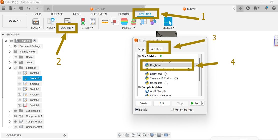
- Go to Utilities > ADD-INS > Add-Ins.
- Select Dogbone from the list.
- Enable Run on Startup.
- Click Run to activate the add-in.
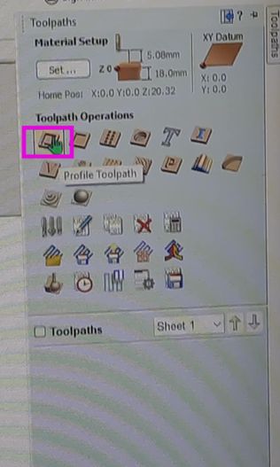
- Go to the Toolpaths tab (right panel).
- Choose the appropriate toolpath type:
- Profile Toolpath – Cutting along the vector.
- Choose the correct tool (End Mill, Ball Nose, V-bit, etc.).
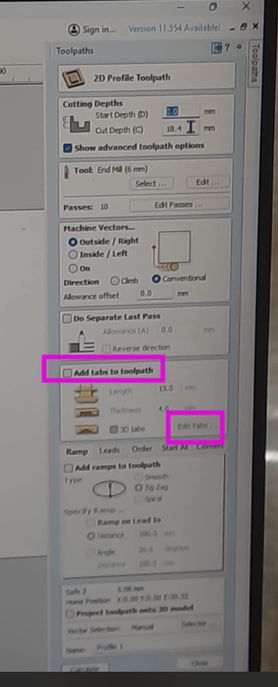
- In the Profile Toolpath settings, find the Tabs Section.
- Check "Add Tabs to Toolpath".
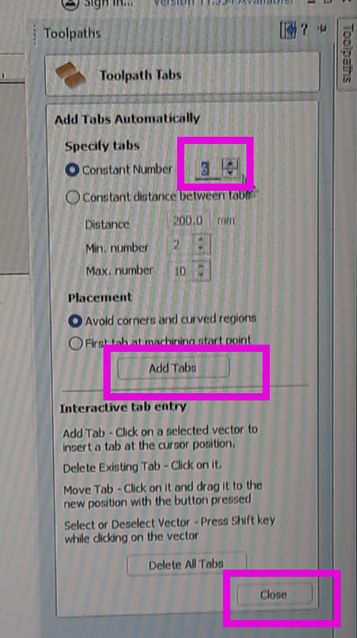
- Click Edit Tabs → The software will place tabs automatically, or you can manually click along the cut path to place them where needed. Tabs are very important in CNC machining as when cutting parts come out of a larger sheet of material(wood for me). Their primary role is to keep the cut-out pieces from moving during the machining process. Without tabs, once a piece is fully cut, the spinning router bit can catch the loose piece, potentially causing it to fly off (a safety hazard!) or damaging the piece and the tool. Tabs act like small bridges that hold the part in place until the entire cutting process is complete. You then manually break or cut these small tabs to free the finished pieces.
- Position tabs where they provide the most stability (e.g., corners, long edges).
Roadmap
My learnings from the sessions!!(both regional and global)
Understanding Material Feed Direction in CNC Milling:
The material feed direction is the direction in which the workpiece moves relative to the cutting tool during machining. This is crucial because it directly impacts: the surface finish –whether the cut is smooth or rough. Tool wear and efficiency –influences how long the tool lasts and finally chip evacuation –controls how material is removed during cutting.
Climb Milling (Preferred for CNC)
The cutter rotates in the same direction as the material feed. Ex: If the tool is spinning clockwise, the material moves right to left.It also produces less tear-out and a better surface finish.
Conventional Milling
The cutter rotates opposite to the material feed direction. Ex: If the tool is spinning clockwise, the material moves left to right.It also causes more friction and rougher edges but helps with certain cuts.
Drills and Mills
Drills: Move only in the Z-axis (vertical direction) and mills (End Mills): Move in X, Y, and Z directions, allowing lateral cutting. It is important to know their difference because it ensures the right tool is chosen for the task e.g., drilling holes vs. cutting shapes and it helps prevent tool breakage and improve machining accuracy.
NOTE: We use end mills for CNC machining!
Group Assignment
Our CNC machine-ShopeBot
ShopBot is a digital 3-axis milling machine that can machine large target material into high-precision 3D shape.
The main machinable materials are wood, plastic, brass and others, but it does not machine metals.
Shopbot is a 3 dimensional milling machine whcih follows the tootpath and measurement based on the design files arranged on thw machine software.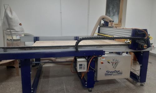
ShopBot PRS Standard CNC - Specifications:
Safety Guidelines
Softwares and Machines used
Some of the softwares and machines used that we used are:
To learn more about the group assignment go to to this website.
Individual Assignment
This week’s assignment—Make (design + mill + assemble) something big—was super exciting because we finally got to design and build our own furniture! I was honestly thrilled. For my project, I designed a modular corner stand. I wanted to create something functional that fits snugly into a corner while offering display or storage space. The cool part? It’s modular—made of interlocking parts that fit together without needing screws or complicated joinery (though I definitely ran into some surprises with material tolerances!).
The design includes a base and several upright panels with interlocking teeth that slot right in. I aimed to keep it simple but sturdy.
I started off my design by creating parameters. Instead of typing numbers everywhere, you give names to dimensions (like width or height) and use them in your design.

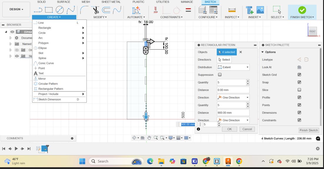
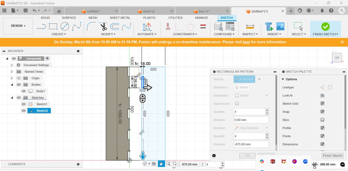
Then rectangular pattern is a tool that lets you duplicate objects (sketches, features, bodies, or components) in a grid-like arrangement along two directions (X and Y axes). I used those rectangles to form the negative space or the cutouts on the base piece. By creating a series of these rectangular extrusions and then subtracting them from the base, I created the slots where the vertical partitions would later be inserted. The rectangular pattern allowed me to easily create multiple equally spaced slots.
Convert the design into components (Right-click → Create Component from Body).
Go to Assemble > Joint.
Select the face of the two components you want to connect.
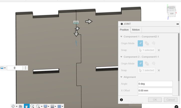
Then press "M" and turn 1 of the components to 90 degree.
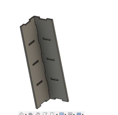
Then go to the "Top view" and then create a new sketch and draw the lines where I highighted with thick brown lines. Then go to Create>Sketch>Conic Curve and make a curve joining the other 2 line segments.
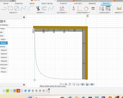
Then I extruded it by the parameter "thickness" that I created earlier.
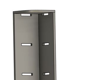
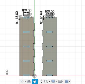
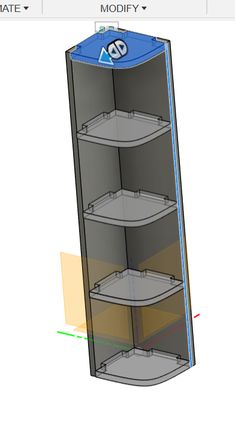
Then to create the teeth: I measured the dimensions and sketched them on the top partition and then I extruded it negatively(to cut it) and this is how it looks!
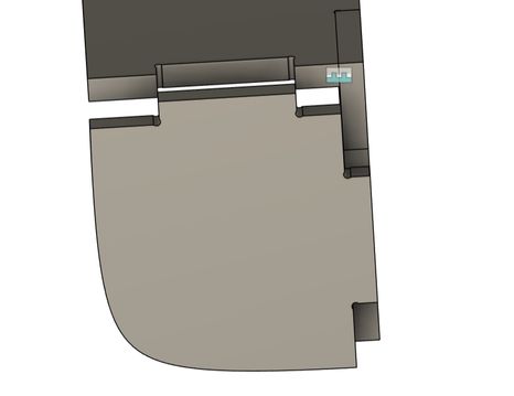
Then I used the rectangular pattern and set the quantity as 5 and spaced it properly!
A Dogbone
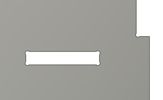
A dogbone in Fusion 360 is basically a really cool trick you use when designing something that’s gonna be CNC milled. You know how end mills are round? That means they can’t cut perfect sharp inside corners, so if you try to fit something exactly in a slot, it won’t go in all the way. It looks like a bone you give to a dog in cartoons (hence the name lol). You usually use them when designing press-fit joints, like in CNC woodworking.
Download Dogbone here! and I referred to this youtube tutorial. Though I use Dell, it proved out pretty helpful to me.

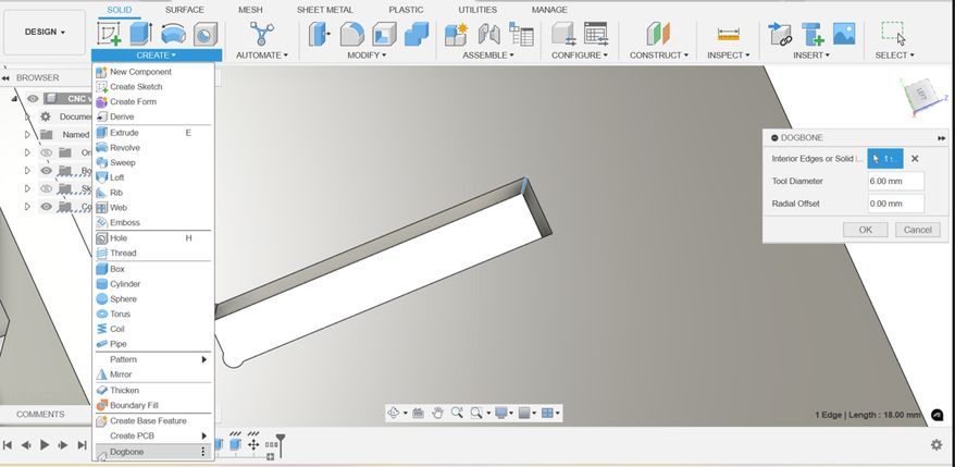
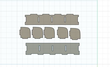
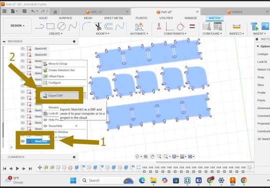
After that create a new sketch and a plane of size(1200m by 2400 m) and then lay out the components of your design 1 by 1. This is to export the design as dxf file. Press p-a shortcut and then press on the latest sketch and then right click and you will see the option "export as" and select dxf file.
This is the design I uploaded in sketchfab and I think that it looks pretty awesome!
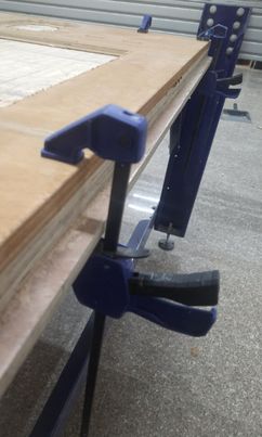
Firstly we must load the wood on the machine! Then we need to set the clamps like this so that the board does not fly off. Setting clamps properly ensures safety by preventing the board from flying off, which could cause injury, while also keeping it stable for precise and accurate cuts or milling.
First I set the page dimensions to my actual board dimensions and also inserted the board thickness.
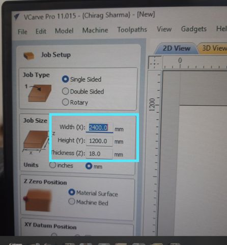
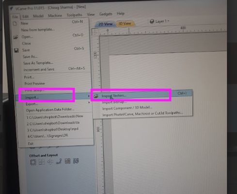
Now select all the imported files and go to toolpath and add tabs. Then, go add tabs and save the toolpath/file:
Creating Tabs
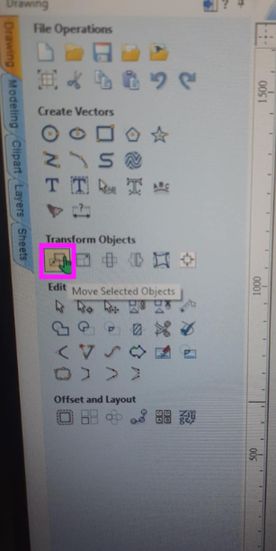
To move the design files, ths shortcut key is select all of the file and press "m". If not go to Transform objects and select this tool.
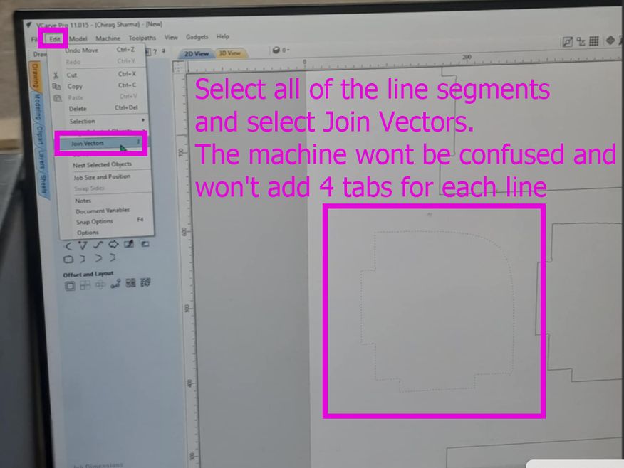
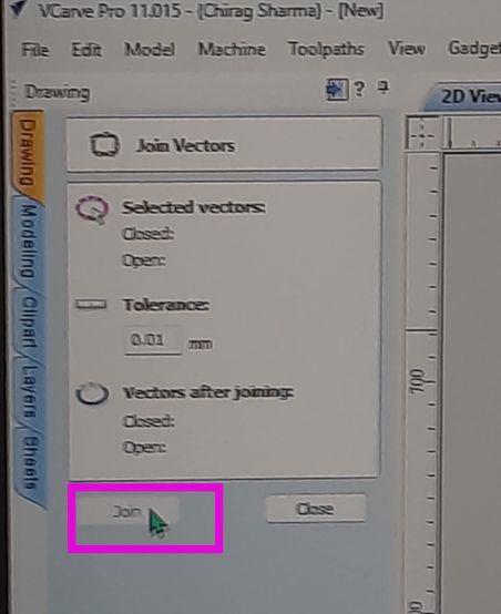
The issue that we face here is that the machine treats the design files as different vectors making about 4(as specified earlier) tabs on each line segment that we dont want. So what do we do? We select all of the vectors, then go to "Edit", then go to "Join Vectors" and then click Join.
Then we turn on the machines! To turn on the shopbot machines, we must turn the main power switch on. The ShopBot control box that we have rotates clockwise to turn ON and counterclockwise to turn OFF.

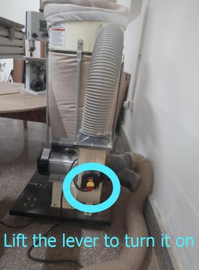
Then we turn on the vacuum that pulls in the dust and chips, keeping the work area clean and improving visibility and safety. To turn it on, we must pull the lever upwards and to turn it off, we must push the lever downwards.
Now, set your x, y and z axis.
For x-axis press on the button 1 and the machine will beep once and then it will automatically position its x and y axis as 0. I set the x and y axis to the lower-left corner of my material in VCarve. This corresponds to a physical point on the CNC bed that I will also zero my machine's X and Y axes to.For the Z origin, I set it to the top surface of my material. This is a common practice because it allows the software to calculate the cutting depths relative to the material's upper surface. To zero the Z-axis on the machine, I use a touch plate or manually bring the tool bit down to just touch the material's surface.
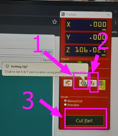
For z axis do these things: Press on the button 2 highlighted. Place the clip to the correct spot like this: Set the plate below the drill: NOW click here to set the z- axis:
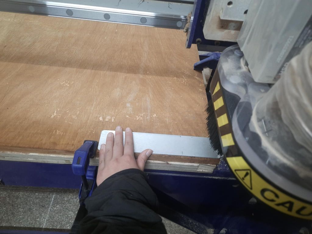
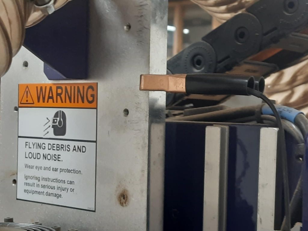 DO NOT forget to take the clip off!
After setting the clamps, turn on the dust collector by lifting the red button shown in the image. Then, select “Cut Part” and start the cutting process.
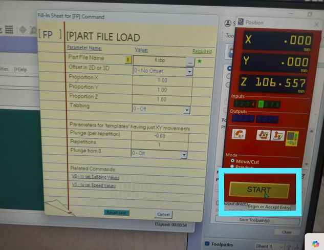
A message will appear and you should press the Start button(green 1) and press ok to continue.
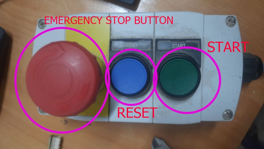
I recorded a video of the process but it was a little too long so I trimmed it using Clideo - a great software and then I used FFmpeg to compress the video. the command that I used are:
cd C:\Users\tshel\Downloads
ffmpeg -i cnc.mp4 -an -c:v copy cutting_compressed.mp4
The video was compressed from 6 mb to 762 kb which is pretty much fantastic. I did not erase the audio because I wanted to warn others about the loud noise that CNC produces!!
After 1 eternity of monitoring the CNC closely, this is the result! For this 18mm plywood, I used a step size of around 2.3mm. This means the router bit would cut through 2.3mm of the material in each pass, requiring three passes to cut all the way through the 18mm thickness. The exact step size can vary depending on the material, the tool being used, and the desired cut quality.

Assembly-Used Thors hammer!🔨 🔨 🔨
Assembling the design was a little harder than I expected. I thought that all of my pieces would fit like a block of puzzle without giving any issues. However life gave me lemons instead of orange to create orange juice, so the wood that I used was inconsistent regarding its thickness which ranged from 17.3 mm to 18.5 mm, so the teeths did not fit perfectly because my design was created for wood consisting of thickness 18 mm. For that I along with Yangtshel Wangyel and our local instructor Mr.Anith Ghalley did some manual work together with Thor's hammer as you can see!
VIR: Very Important Reminder: Clean up the space

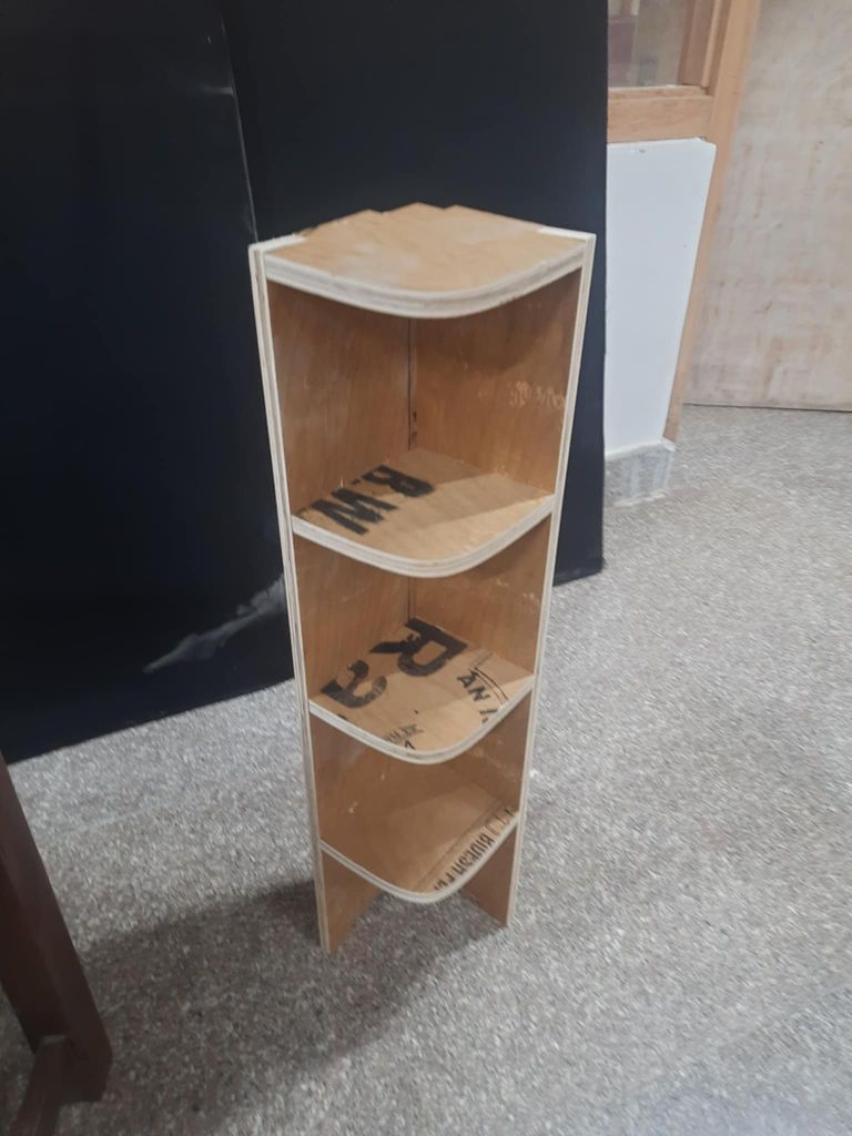
HEROSHOT!
Files
You can access the files here
Corner_stand_design
Corner_stand_f3d file
