Week 7: Computer Controlled Cutting
- Complete your lab's safety training
- Test runout, alignment, fixturing, speeds, feeds, materials and toolpaths for your machine
- Document your work to the group work page and reflect on your individual page what you learned
ShopBot PRS Standard CNC Specifications
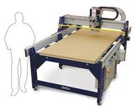
The CNC machine at our lab is the ShopBot PRS.
Workspace: 2400mm x 1220mm
Speed: We used the speed of 10000 RPM to cut our design
Software: ShopBot Control Software for operation
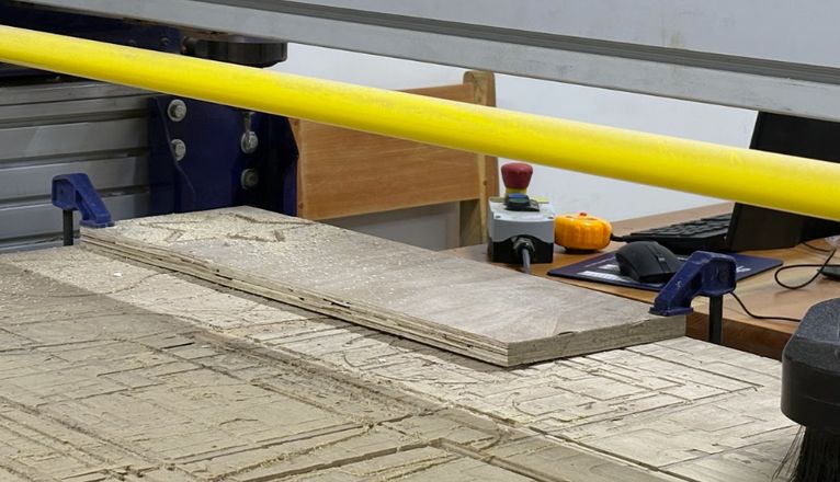
Fixture: Cutting material is attached using clamps.
Setting origins: We use shopbot3 software to set the origins. Proximity sensors are used. For the z axis you have to manually set the origins through the use of zeroing.
Important Components
Here, you can find out more details on some of the most important components about the CNC in greater detail.
Emergency stop button
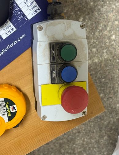
Red button🔴: This is the emergency stop button which will immediately stop the machine when pressed.
Blue button🔵: This is the reset button, used right after turning on the machine.
Green button🟢: This is the start button which enables the end mill to start rotating.
Control Box
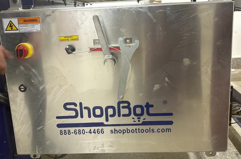
The control box is where the machine is turned on and where the wrench for switching the spindles are kept.
End Mill
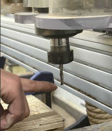
An end mill is a cutting tool used in CNC milling machines for precise material removal. Unlike drill bits, it can cut vertically (plunging) and sideways (milling).
Clamps
Generating toolpath
I am using the software VCarve. You can follow along with me here.
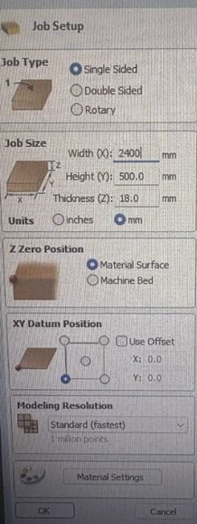
Open VCarve and set up the width and height.
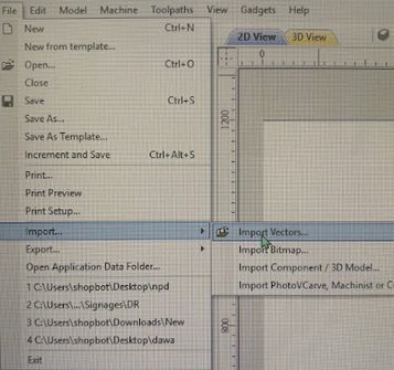
Go to file> import> import vectors and select your dxf file.
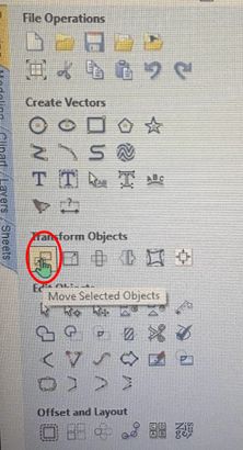
To move your design, select your design and tap on the icon highlighted below.
Now, go to toolpath> profile toolpath.
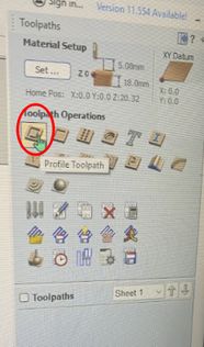
Keep the start depth at 0 and the cut depth to the depth of your workpiece.

Go to 'add taps to toolpath'> 'Edit Tabs' which will take you to 'Toolpath tabs'. Increase the number of tabs according to your design. I made mine 4. Press 'Add tabs' and 'Close' once done. If the lines of each compartment are not recognized as one, select all the lines from one body go to edit> join vectors.
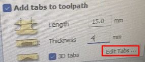
Press close.
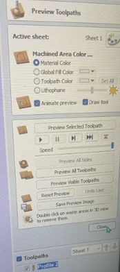
Save toolpath.
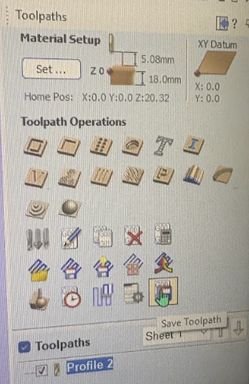
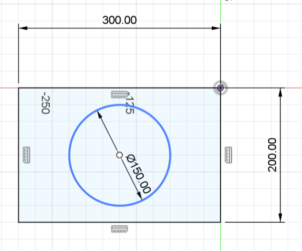
Open Shopbot and import your toolpath file. Set your x, y, and z origins. You can start cutting. This is the simple design we made to test runout, alignment, fixturing, speeds, feeds, materials and toolpaths for our machine
Here is a definition of important terms generated from ChatGPT with the prompt, Define runout, alignment, fixturing, speeds, feeds, materials and toolpaths in the context of a CNC machine.
Runout – Measures tool wobble; excessive runout causes inaccurate cuts.
Alignment – Ensures the spindle, tool, and workpiece are properly positioned.
Fixturing – Secures the workpiece using clamps, vices, or vacuum tables.
Speeds & Feeds – Speed (RPM) controls tool rotation; Feed rate sets movement speed—both affect cut quality.
Materials – Different materials (wood, plastic, metal) require specific tools and settings.
Toolpaths – Defines how the CNC cuts: contour (outline), pocketing (material removal), drilling (holes), etc.
Cutting setting
This is the cutting settings we used to cut our group assignment design.
- RPM:10000
- endmill:6mm, 2 flutes.
- Material thickness:15mm
- Tabs:2
Here are the results!
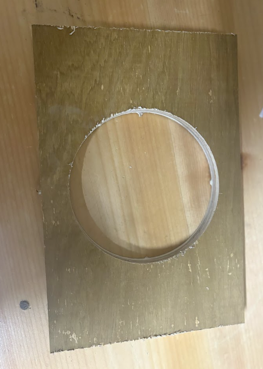
Print to design comparison
The dimensions of our original design is:
- Length: 300mm
- Width: 200mm
- Diameter: 150mm
The dimensions of the cut design is:
- Length: 300mm
- Width: 200mm
- Diameter: 140mm
Safety Measure
"look,listen and smell" during operations for smoke or strange smells!
Wear (PPE)personal protective equipments: protective goggles and ear defenders.
Never leave the equipment running unattended.
Keep hands, hair, and attire away from moving components.
Use suitable feed rates and spindle speeds for different materials.
Tie up long hair neatly.
Collet and tool bit for tightness.
Keep the emergency stop button within reach at all times.
Clean the work area and store the tools and bits safely.
Conclusion
Through this assignment, we were able to gain hands-on experience in using the ShopBot PRS CNC machine, from setting up the workspace to generating toolpaths in VCarve. Understanding key aspects such as runout, alignment, fixturing, speeds, and feeds was essential for achieving precise results. Overall, we had a lot of fun!