Week3 - Parametric Construction Kit
Files in dxf:
Test the laser cutter and get the curf
Here's the link of week3 group assignment which record the process of getting the curf.
Design the Parametric Construction Kit
I design the Parametric Construction Kit by Solidworks and make the kit by wood. Here's my proecess:
Open a new part files in Solidworks.
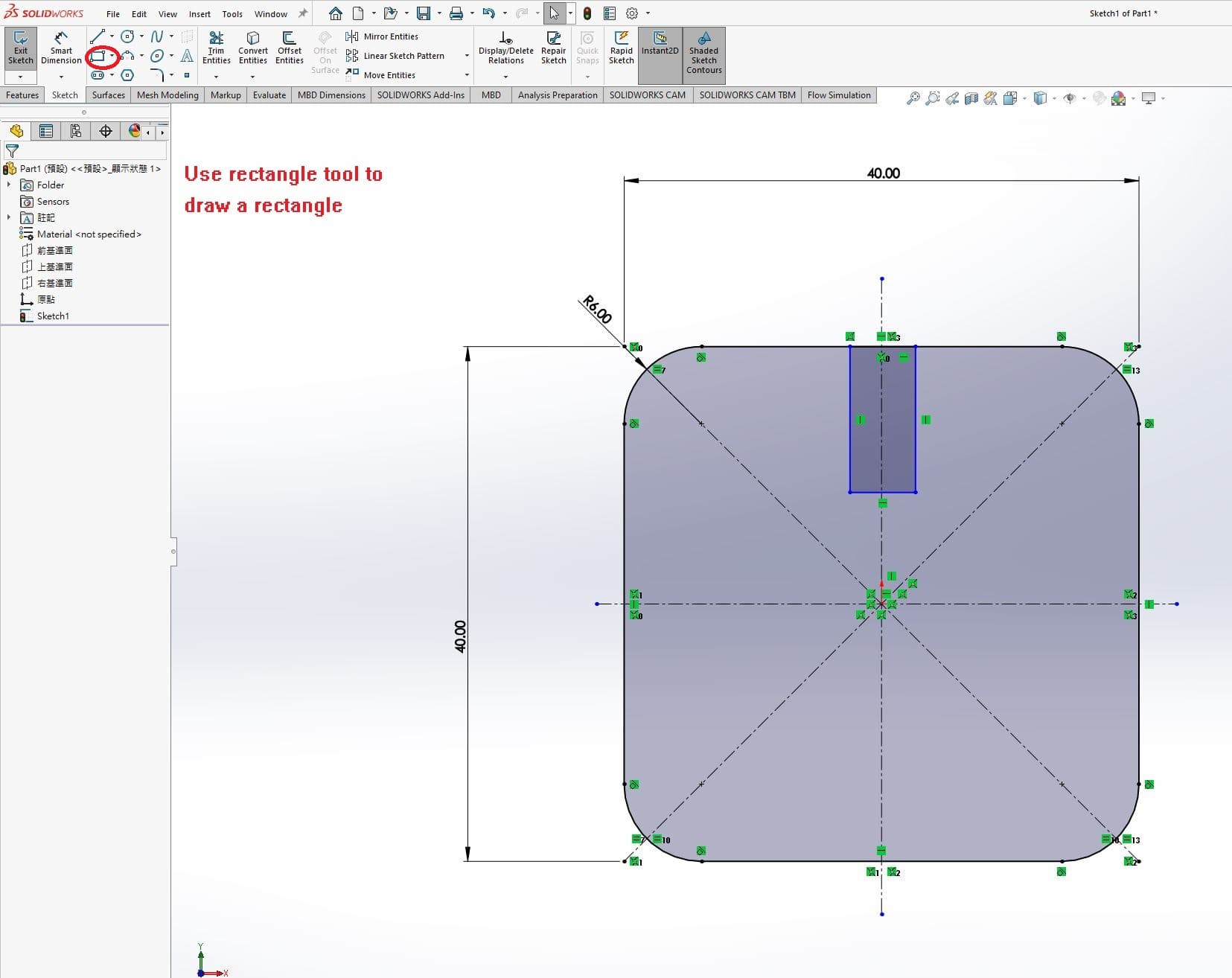
Then, draw a rectangle.
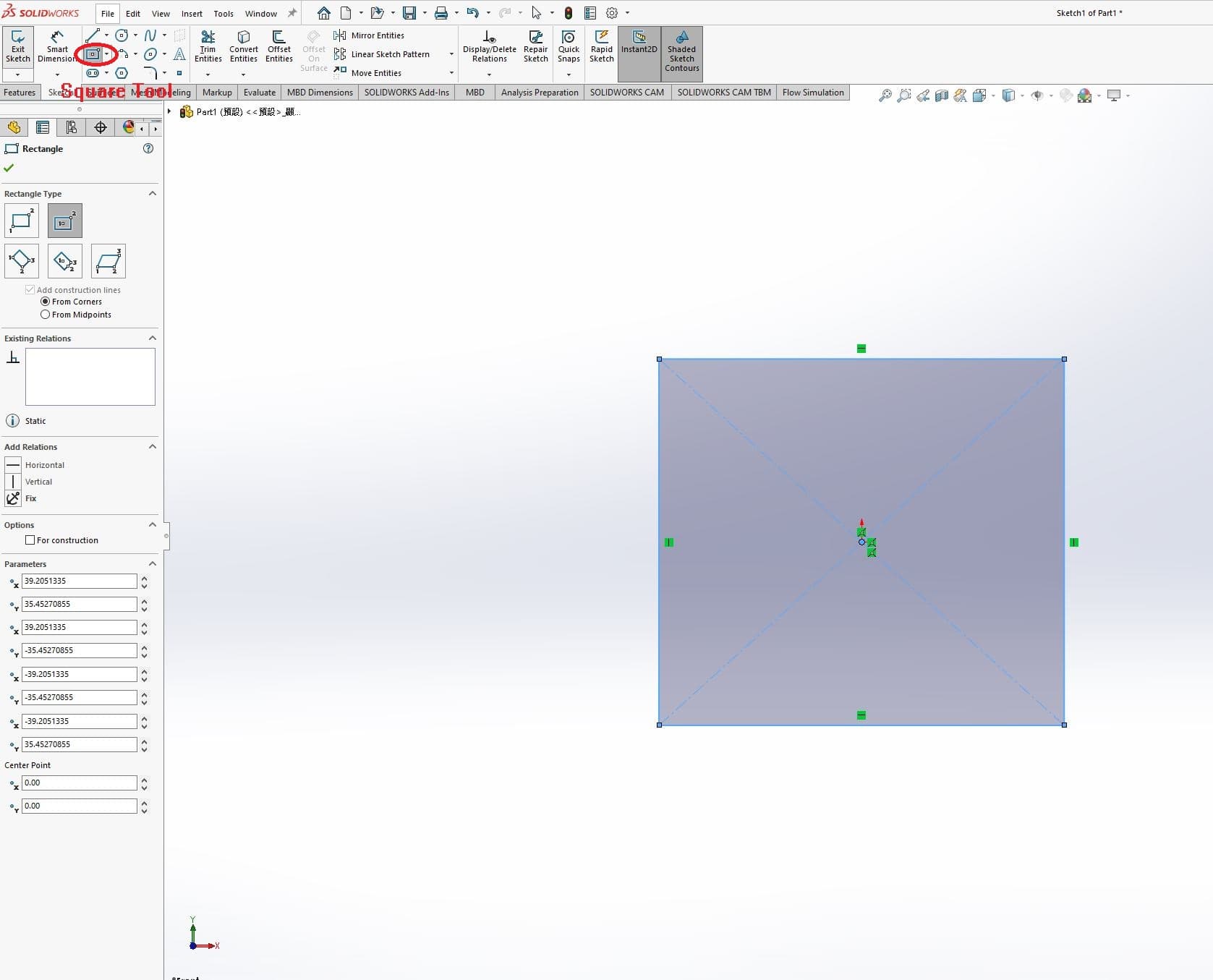
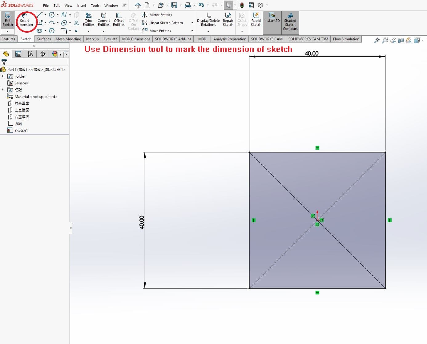
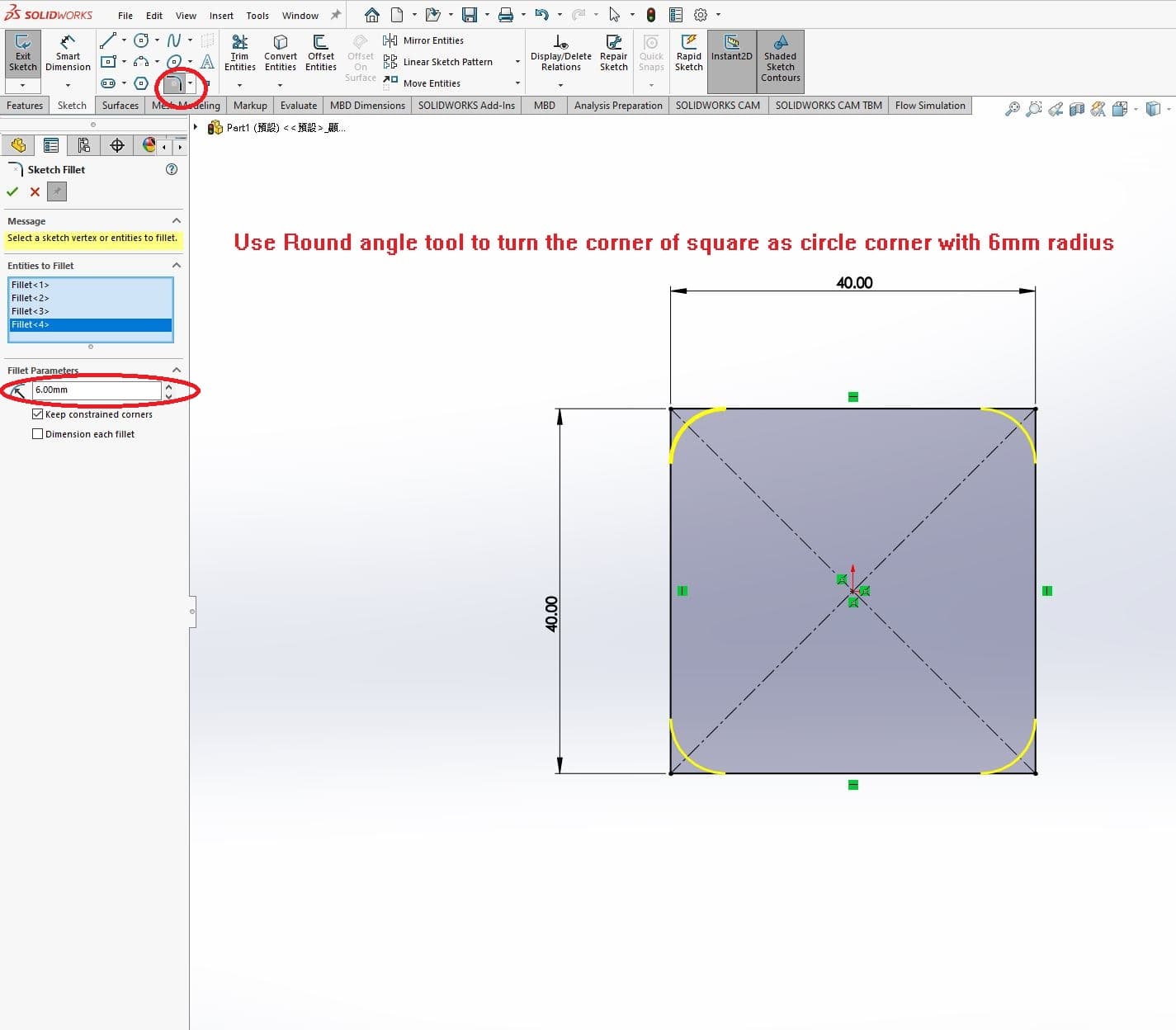
Use the dimension tool to modify the size of rectangle as 40mm * 40mm
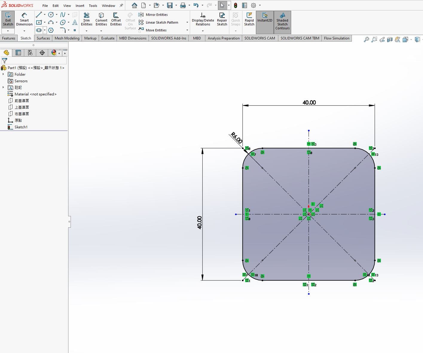
Use the circular corner tool to modify the corner as circular corner with radius 6mm.
Use the center line tool to draw the center line.
Draw a rectangle.
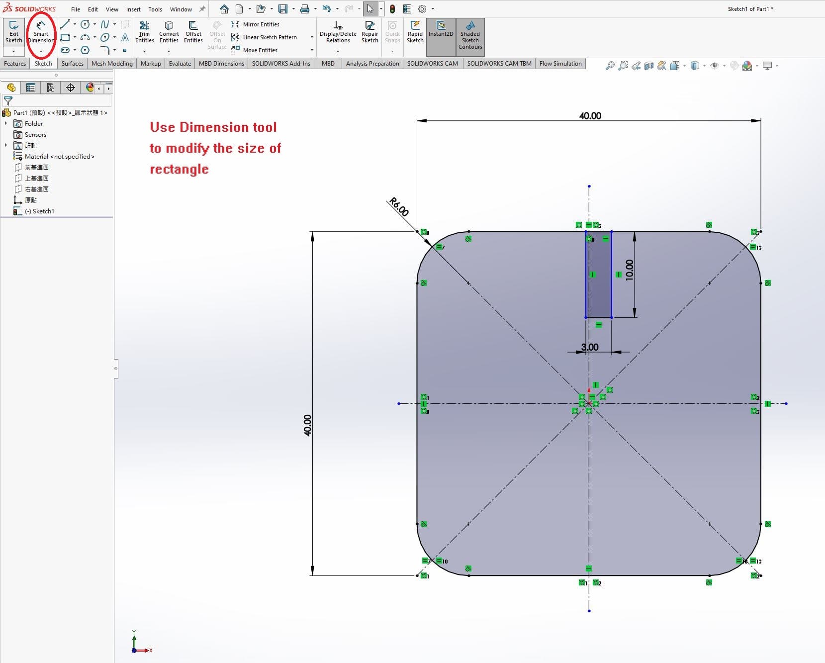
Use dimension tool to modify the size of rectangle as 10mm*3mm.
Centerize the rectangle to center line.
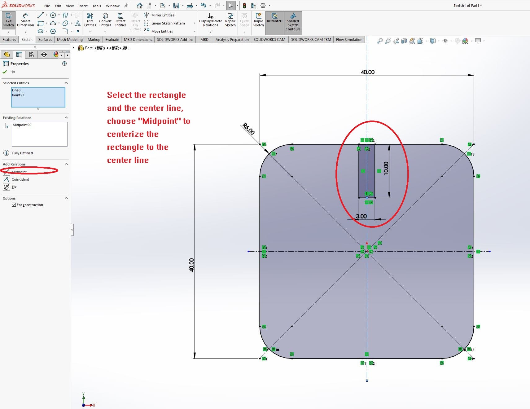
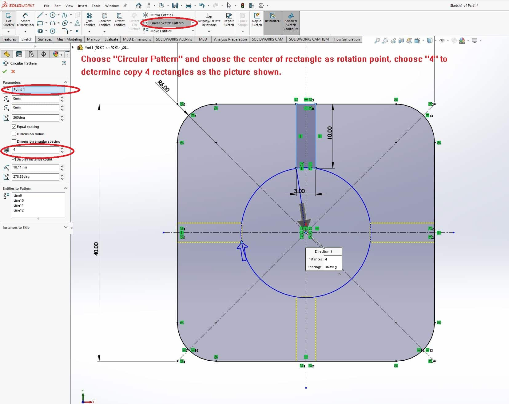
Use the circular pattern to copy the 10mm*3mm rectangles as 4.
Use the trim tool to trim the sketch lines.
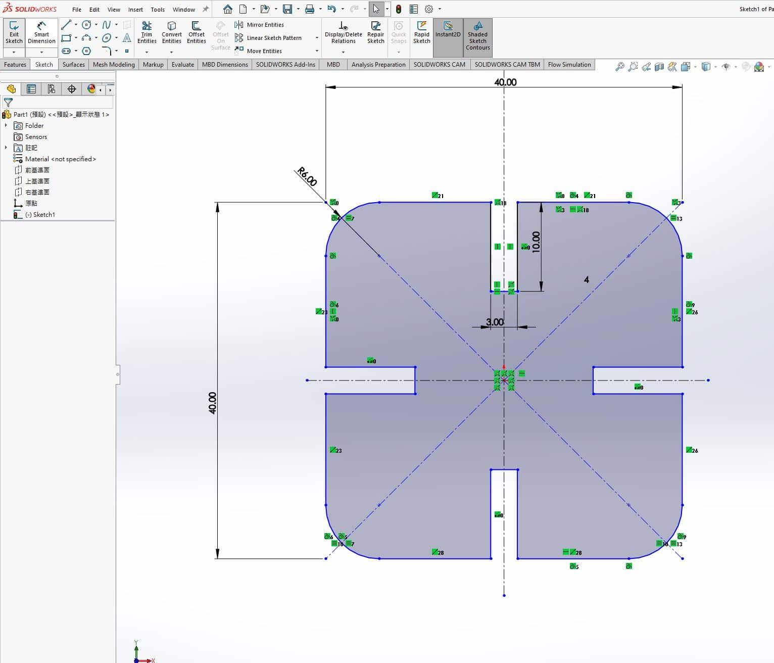
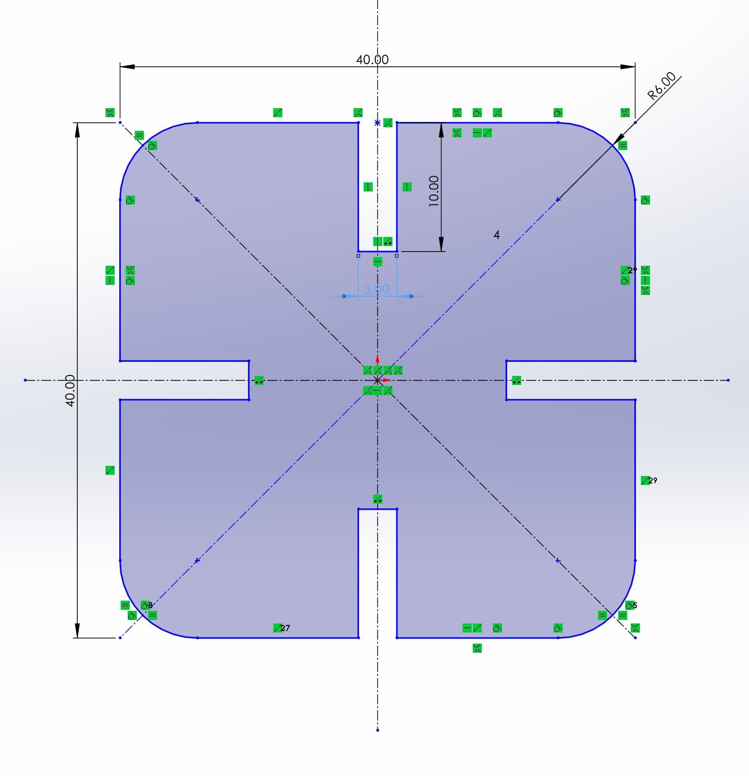
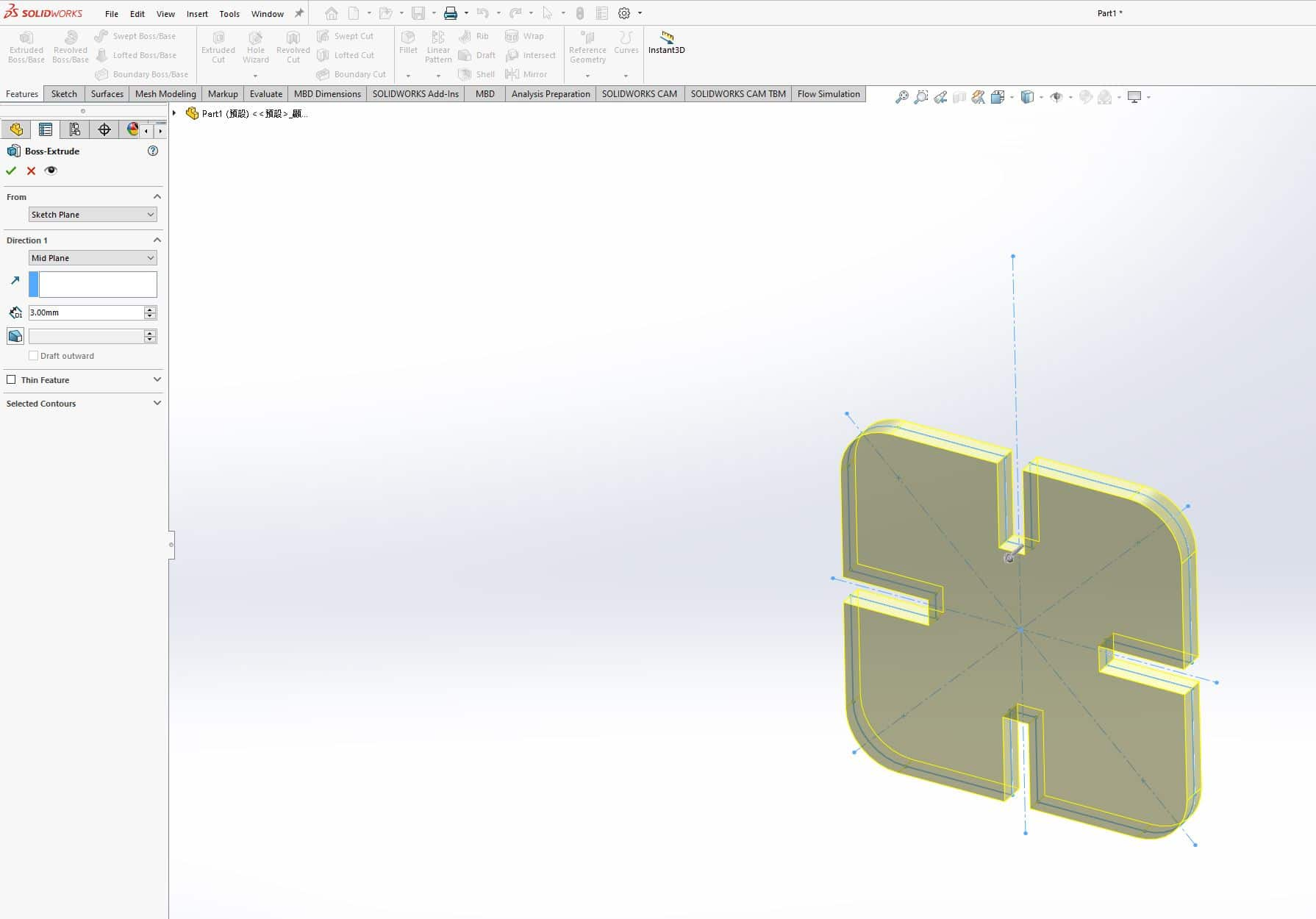
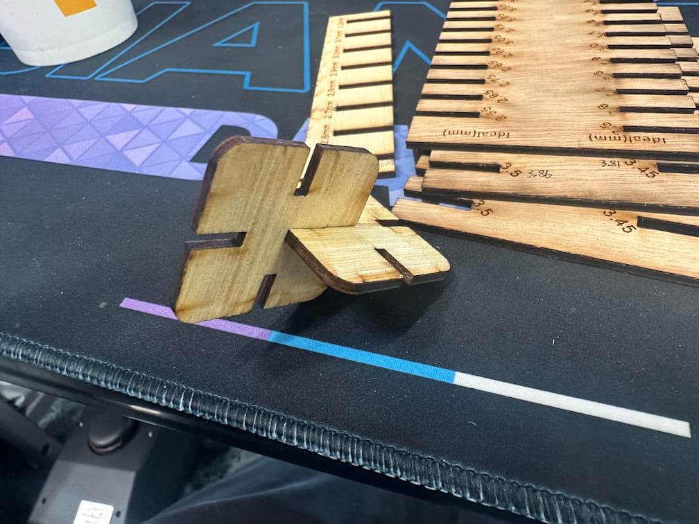
Here's my basic sketch. It's a 40mm * 40mm square with round angle (radius 6mm). There are 4 slots with basic size 3mm width and 10mm long base on each board with thickness 3mm.
Extrude the sketch to 3mm. And save it.
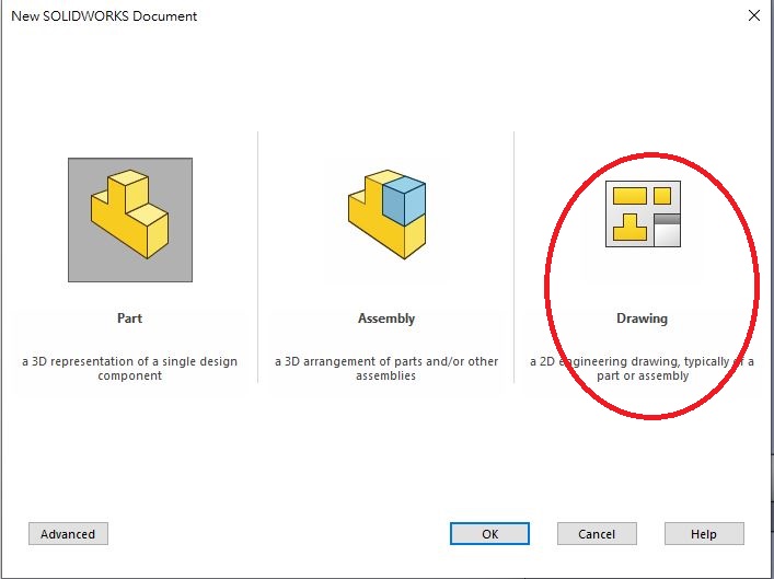
Open a new drawing file.
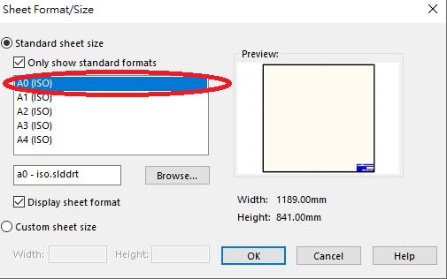
Choose A0 size.
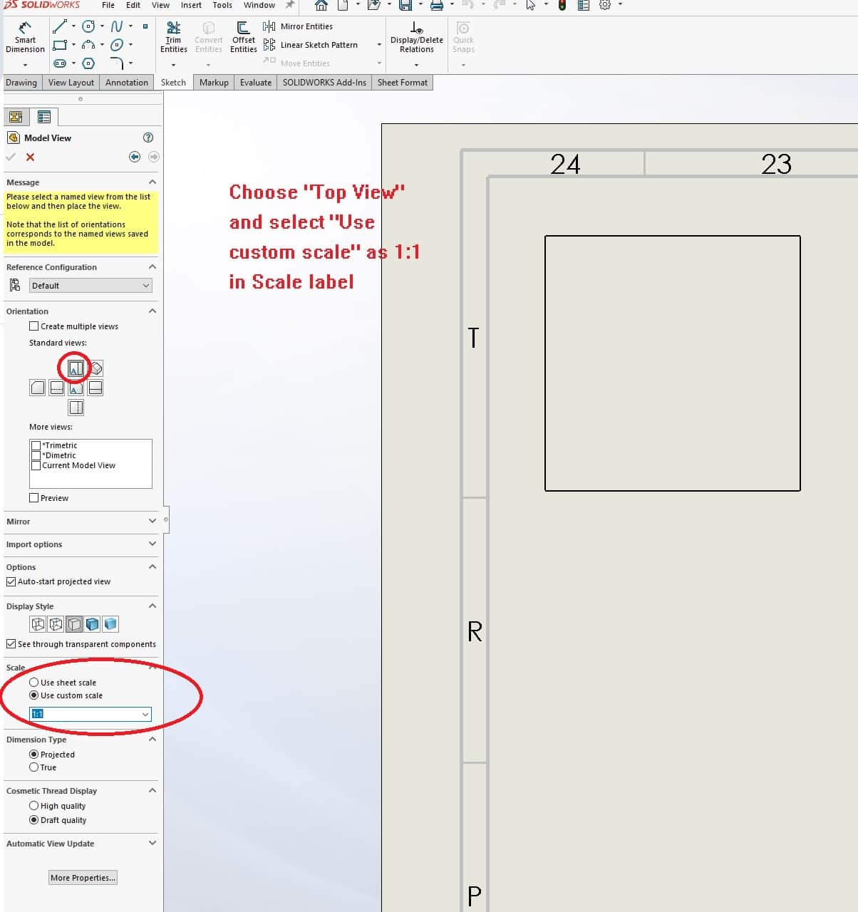
Insert the sketch to the file with 1:1 scale.
Then, according to the curf we found in Group Assignment, We will to decrease 0.242mm cause the kit can be assembled to the slot with interference fit.
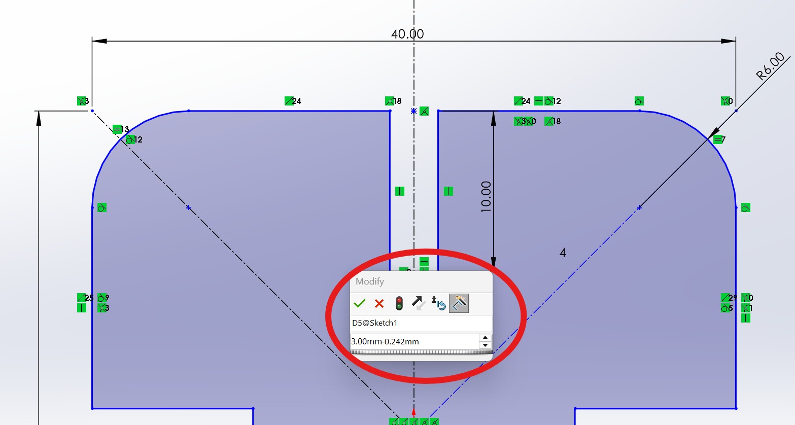
After finishing the sketch, extrude the sketch as 3D parts and generate the engineering drawing, then save as dxf file.
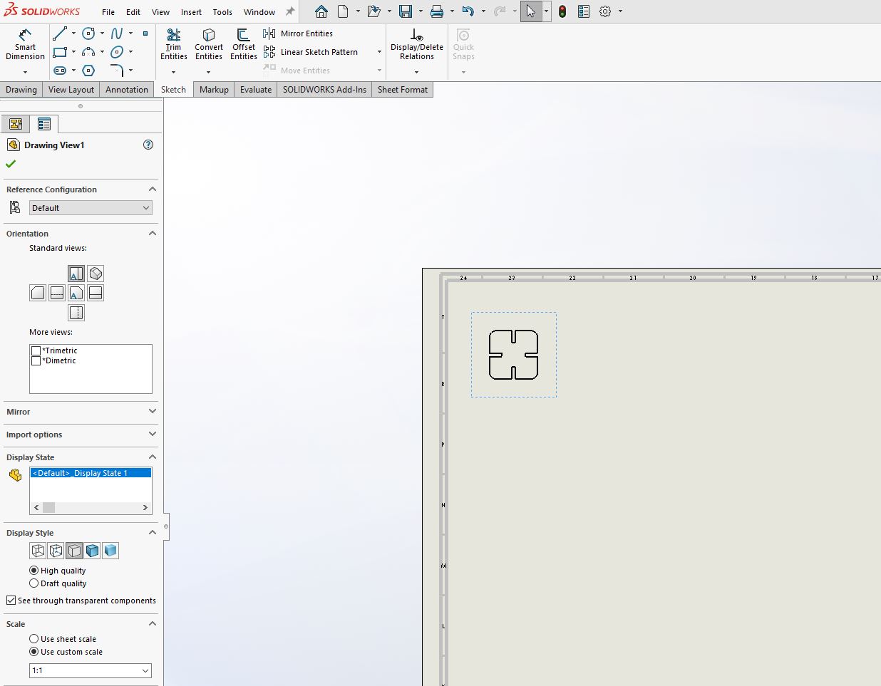
Then, import to CorelDraw and ready for cutting.
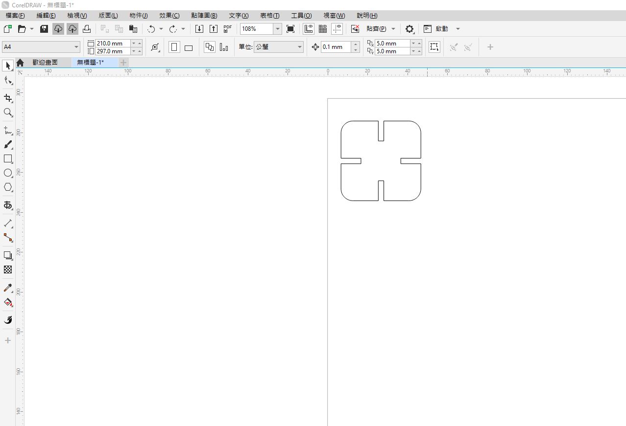
I cut about 16 parametric constrcution kit.
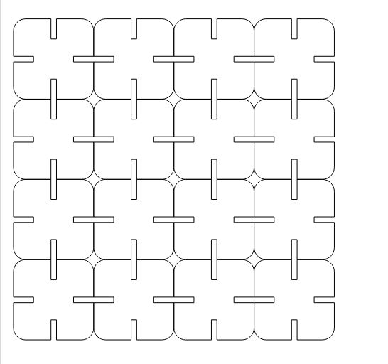
Cutting Power: 80%
Cutting Speed: 20%
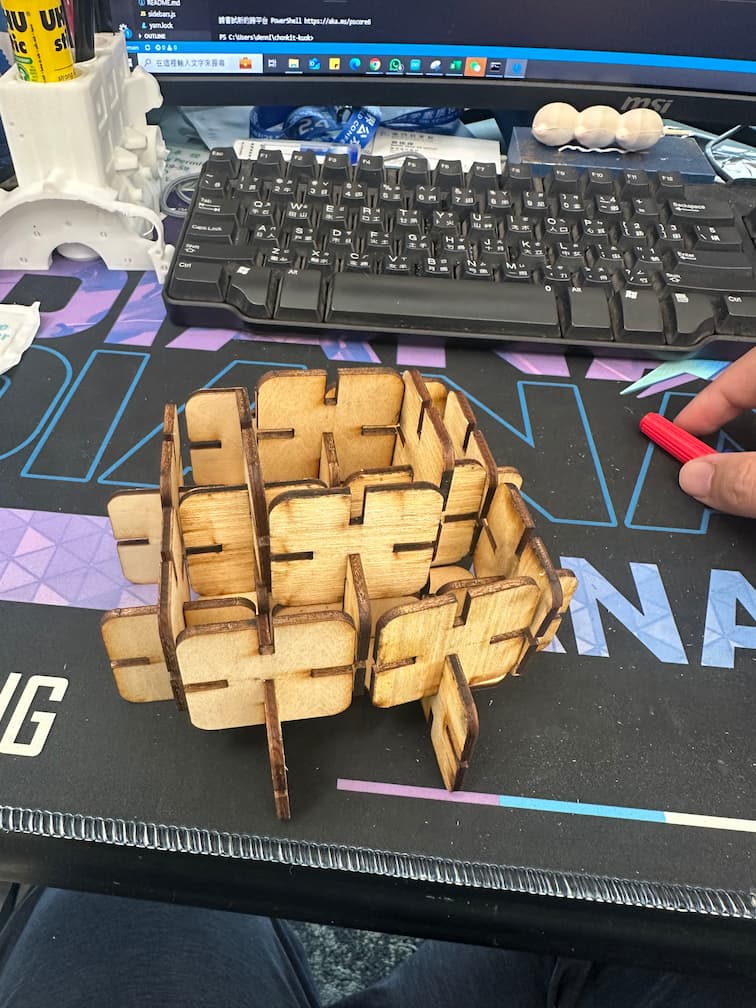
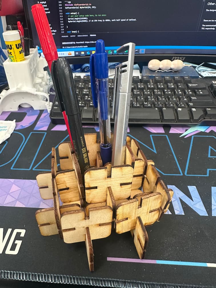
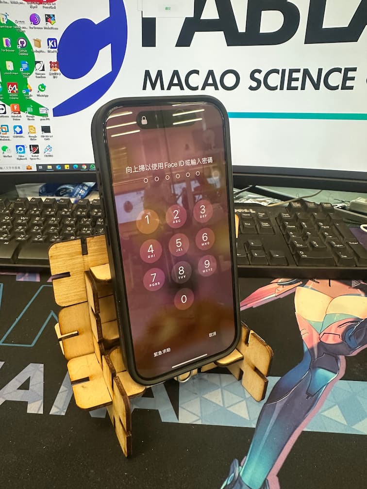
Finally, we can assemble the parametric construction kit and assemble as the shape you like.
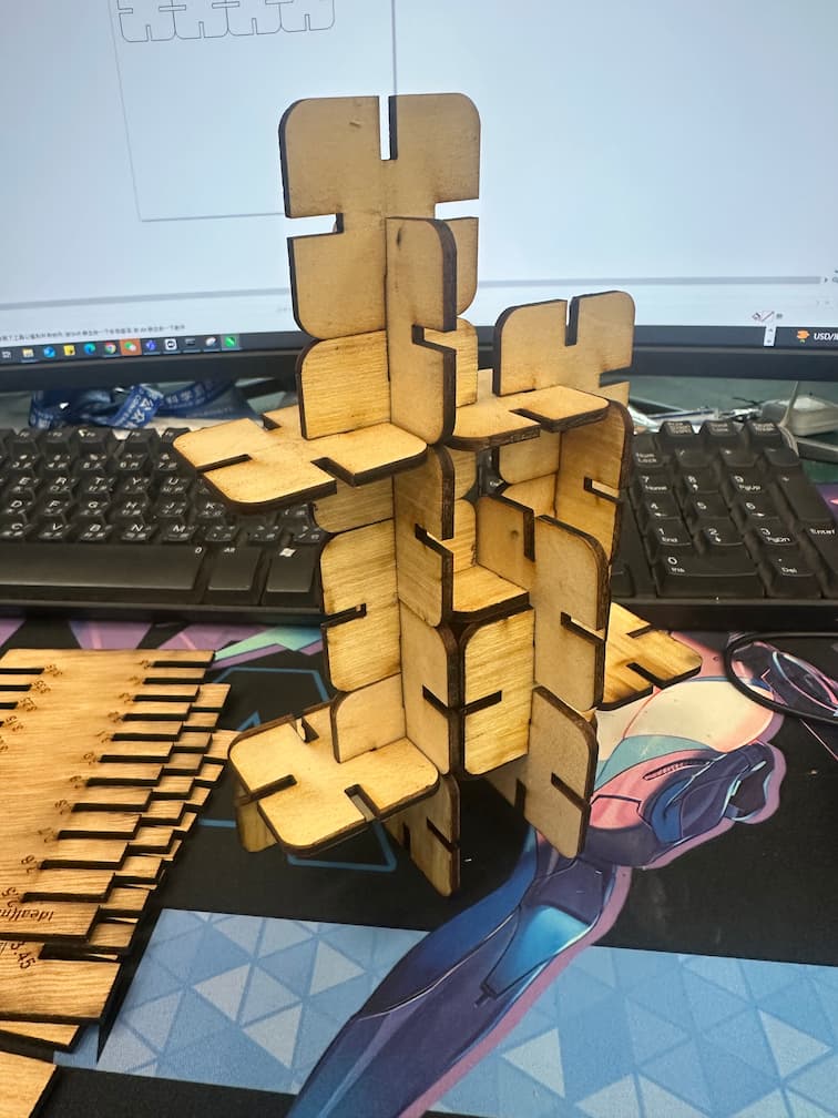
Sometimes it can be assembled as a phone holder.
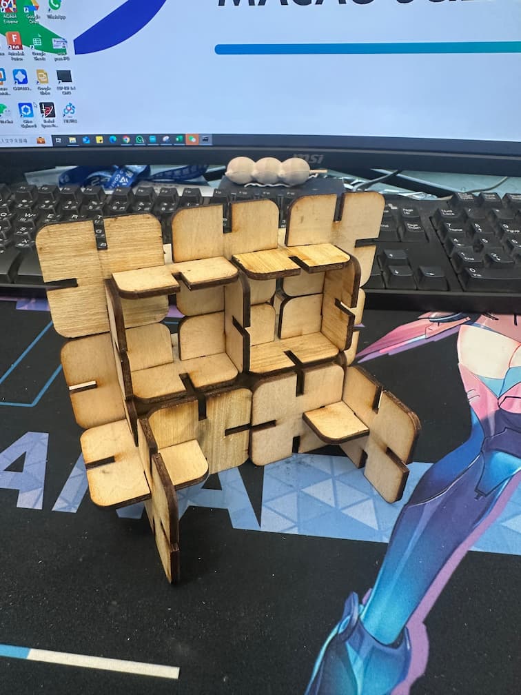
Sometimes it can be assembled as a pen container.
