3D Software
Shared Files
My major is about mechanical designing. I'm trained by using professional 3D modeling software. I have more experience in 3D software - Solidworks & OnShape.
OnShape
Onshape is a online software about 3D modeling. It's free and the operating logic is similar to Solidworks.
It's easy for freshman who has no experience in 3D modeling with free. And official studying materials are provided in their official website.
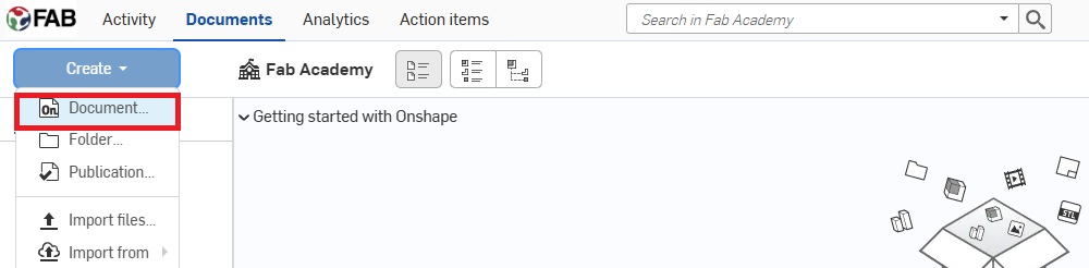
You can open a new file to modeling a new 3D model.
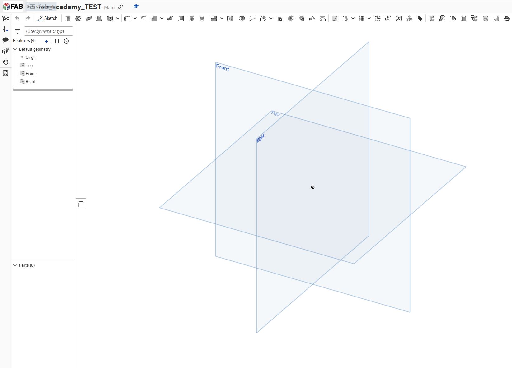
The UI will turn to this page. It will show 3 views - front, side and top view.
The modeling logic in Onshape is:
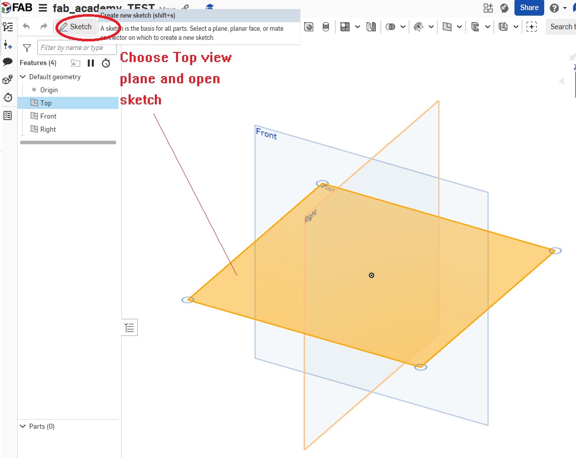
- Choose a view/plane and open a sketch
- Draw the sketch and mark the size
- Extrude or Remove the sketch
In this example, I design a cyclinder with a circular hole.
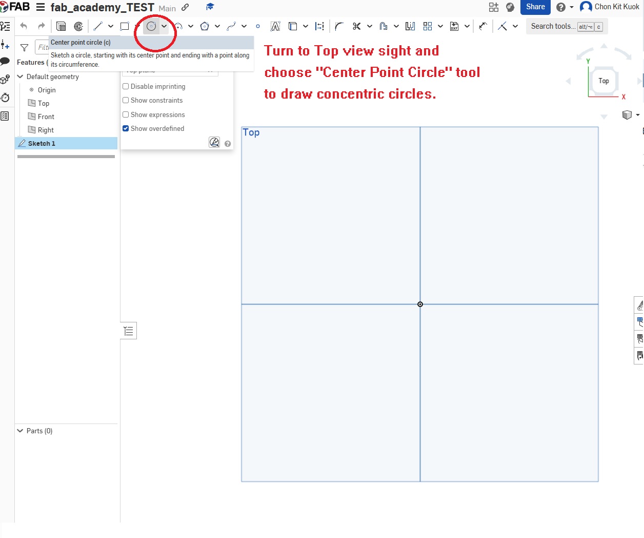
Step1: Choose a plane and draw the sketch
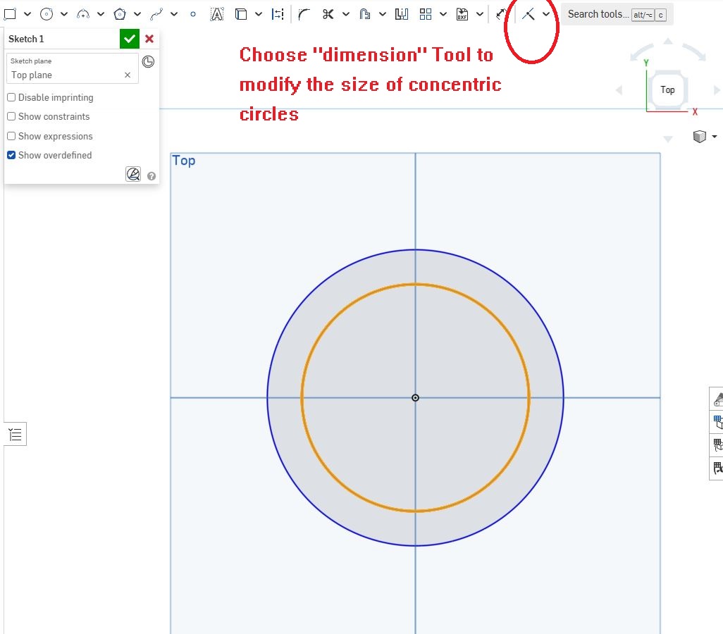
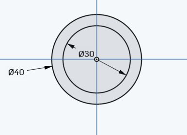
I will choose top view in this step and draw a concentric circles with diameter 40mm and 30mm.
Step2: Choose the sketch and extrude the sketch
After finishing the sketch, choose "extrude" tool and input the thickness. Let us model a cylinder with 200mm height.
First, choose the extrude tool.
![]()
Then, choose the sketch and input the variable of thickness. In order to setup the origin point as the centroid of the 3D model, remember check the "Symmetric" checkbox.
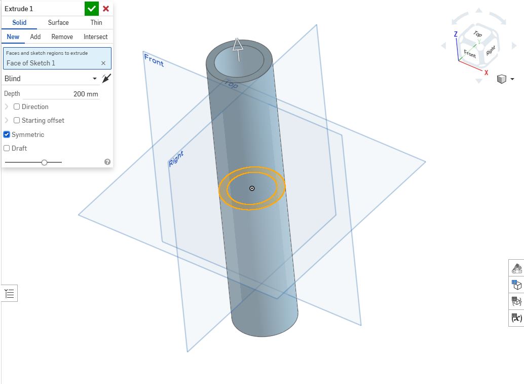
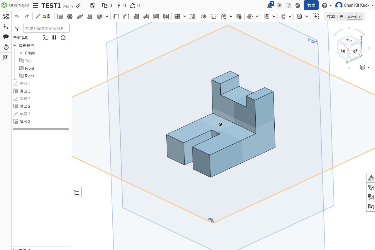
Finally, a cylinder with concentric circles (dia. 40mm & 30mm) finish!
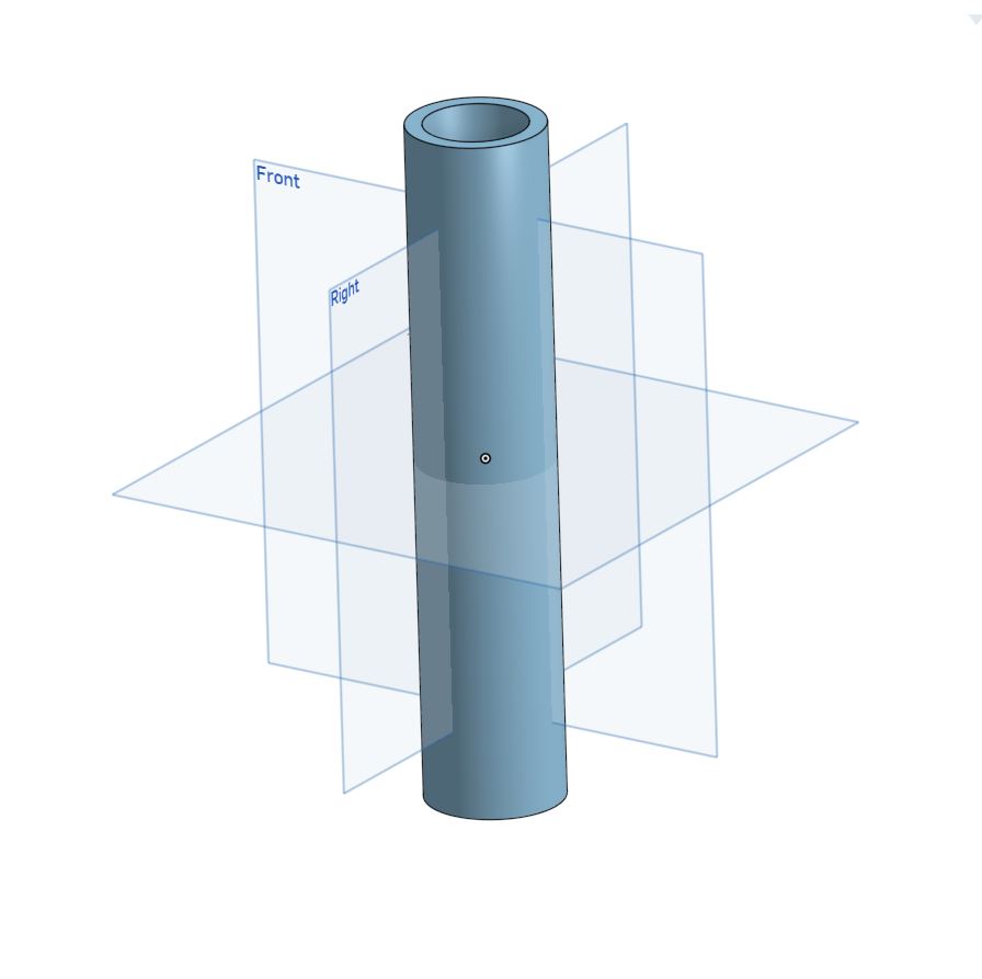
Here's the finish 3D model.
That's the basic 3D modeling steps in OnShape. It's useful in parts modeling but not good at assembly project management. By the way, I will choose another 3D software - Solidworks.
Solidworks
Solidworks is a industrial 3D modeling software. It can also used for flow simulation, CAM, etc. And the basic modeling logic is similar to OnShape.

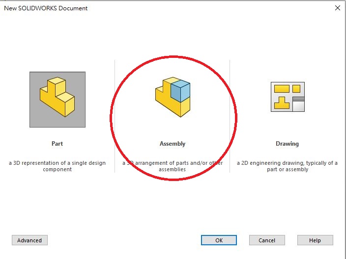
In Solidworks, there are 3 basic modeling mode:
- Parts
- Assembly
- Drawing
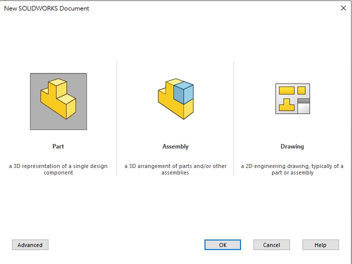
Parts function is used for modeling parts only, like Onshape I introduce before. Assembly function is used for assembling difference parts into one project. Drawing function is used for generate the engineering drawings of 3D models.
In Assembly, there are two logic the build up the assembly project.
- Generally, Finish all the parts and assembly.
- Top-down design - Edit parts when modeling assembly project.
The first design logic is used under this situation: for example, an aseembly project is shown as below. It is a standard damper.
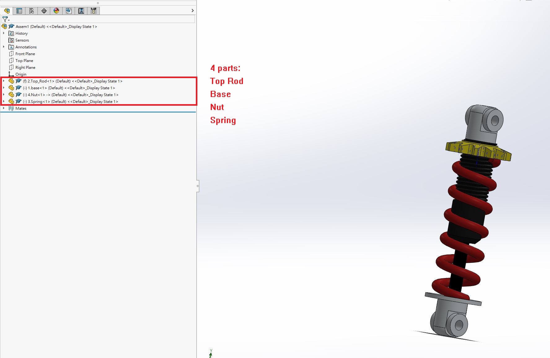
There's assembled by 4 parts:
- Top Rod
- Base
- Nut
- Spring
All of the parts are standard design. In this situation, it's suitable to assemble the parts which are pre-finish modeling.
Top-Down Design
Let's us to explain Top-down design simply. We use an existed parts or design to modeling other parts in assembly mode. There's a self-designed example:
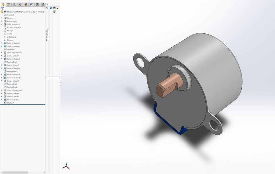
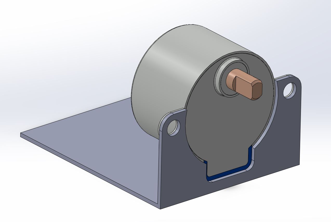
It's a 3D model of standard 28BYJ-48 stepper motor. I will show the steps of designning a motor mount based on its features.
Open assembly mode
Let's open a new file in assembly mode.
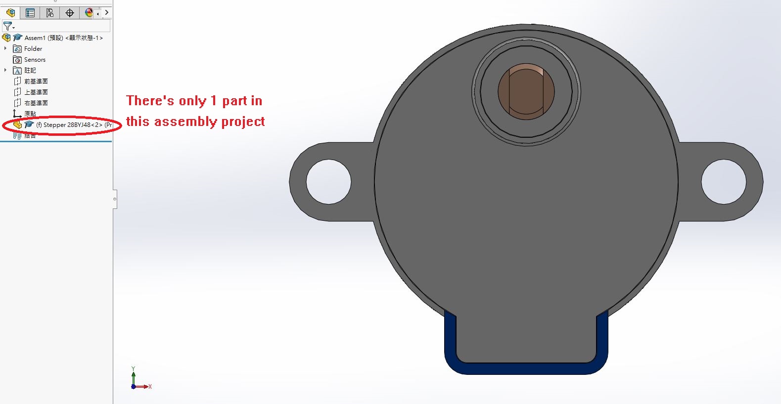
Then, insert the stepper motor model.
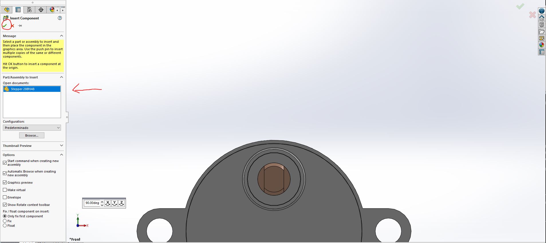
You can see there's one part in this assesmbly project.
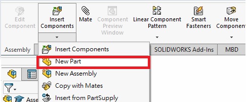
Add new part and existing parts
Let's us add a new empty part. And press "Edit component".
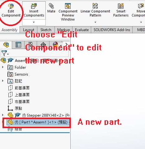
Now you can modeling a new part based on the consist features. For example, the key feature of a motor mount is the holes of stepper motor. So we choose face that contain holes to draw a sketch.
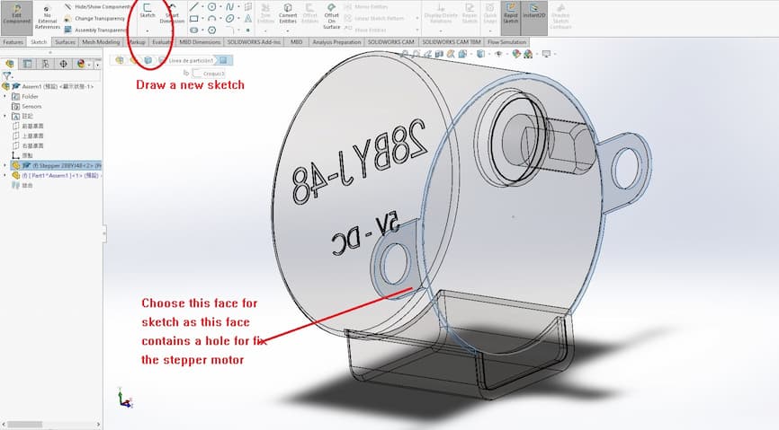
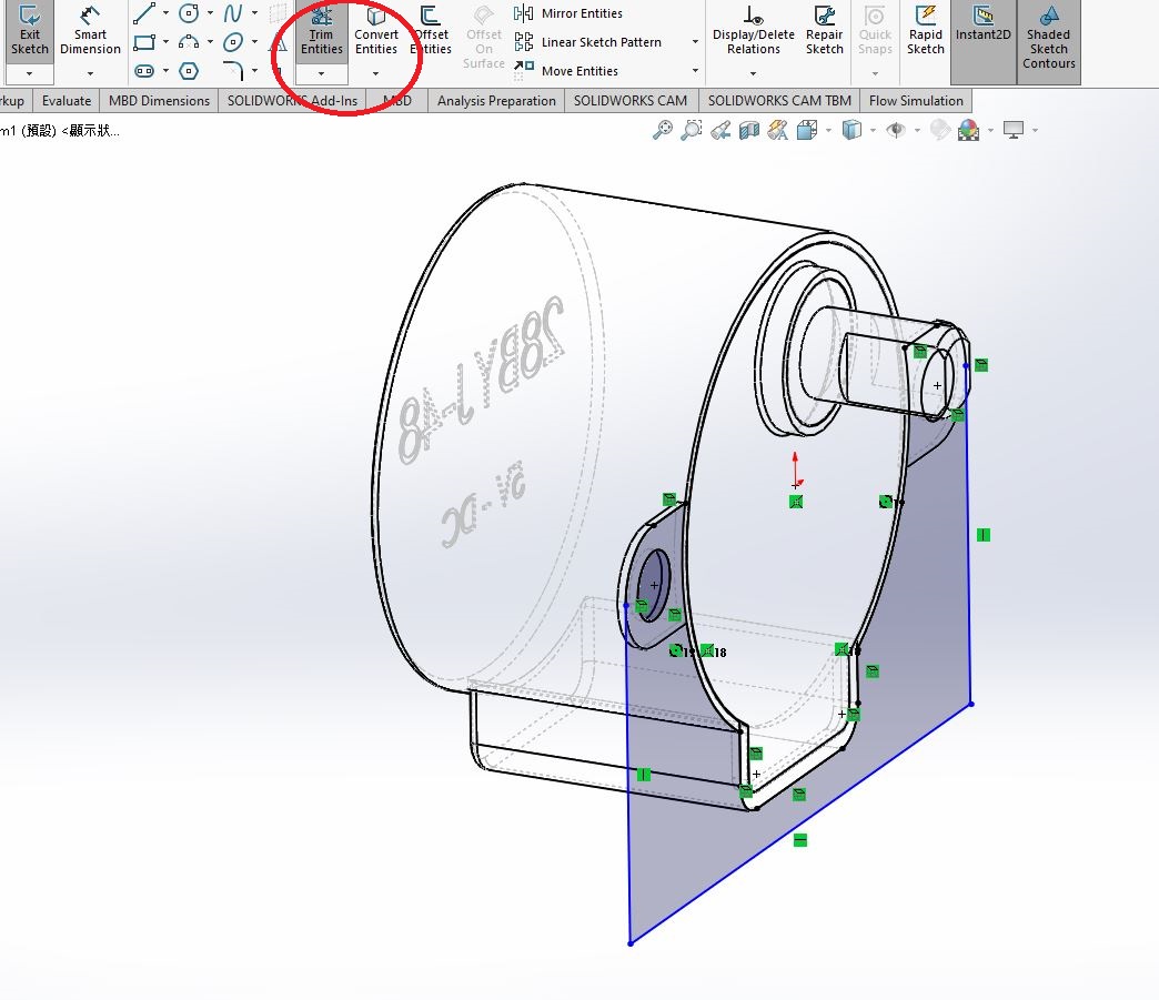
Draw sketch
Choose the essental contour around the motor hole and choose "Convert Entities"
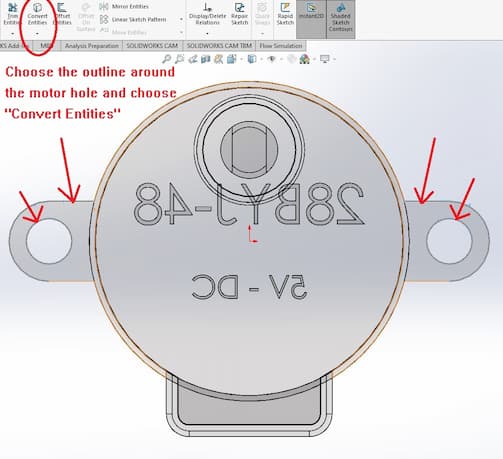
And you will get the motor features to your sketch. Let's us finish the sketch.
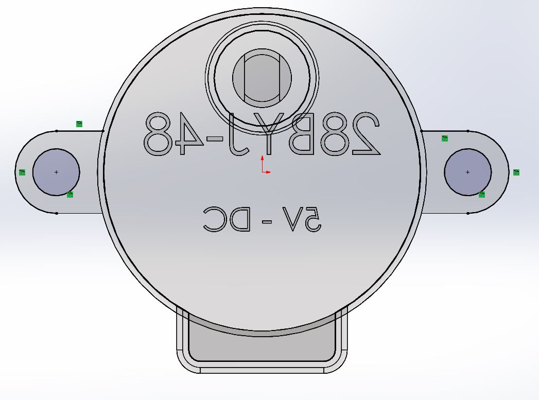
Use "Trim Entities" and "Convert Entities" to build the sketch.
Extrude Sketch
And extrude the sketch.
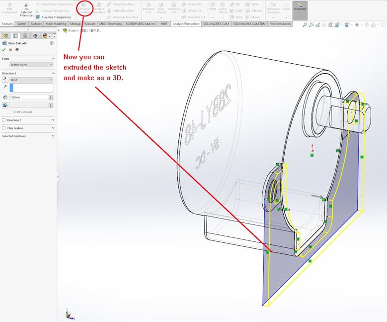
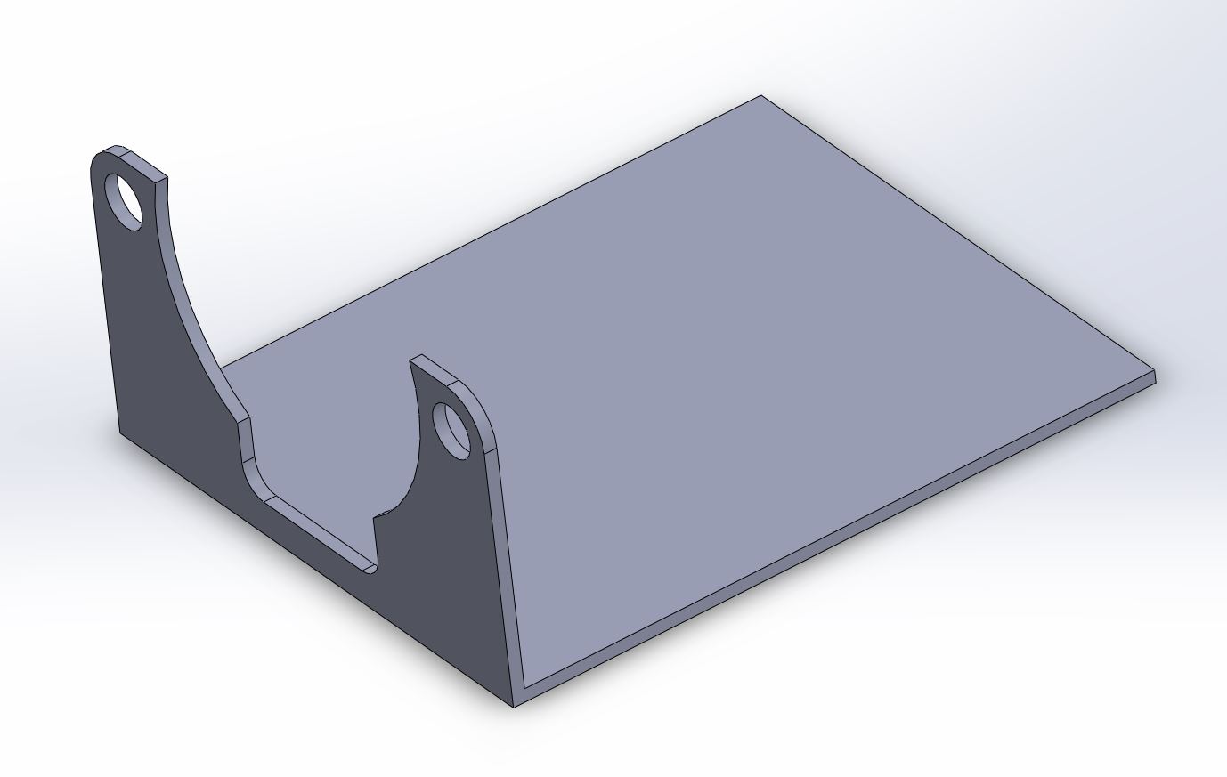
Reply the steps which build another sketch onto other planes of motor mount (Draw a rectangular sketch and extrude). A new part - motor mount is finished.
This new part can be saved as a seperated file. You can go through the next step - 3D printing, Machining, etc.
Conclusion
In the final project, I will design the project by Top-down design method, Solidworks will be used for 3D modeling in my journey of Fab Academy.